LiFe Battery System 48-100 - Electric battery PowerWalker - Free user manual and instructions
Find the device manual for free LiFe Battery System 48-100 PowerWalker in PDF.

User questions about LiFe Battery System 48-100 PowerWalker
0 question about this device. Answer the ones you know or ask your own.
Ask a new question about this device
Download the instructions for your Electric battery in PDF format for free! Find your manual LiFe Battery System 48-100 - PowerWalker and take your electronic device back in hand. On this page are published all the documents necessary for the use of your device. LiFe Battery System 48-100 by PowerWalker.
USER MANUAL LiFe Battery System 48-100 PowerWalker
natural_image
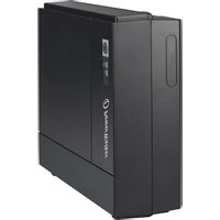
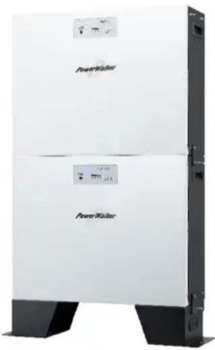
Exterior view of a power refrigerator unit with visible branding and control panel (no text or symbols on the device itself)LiFe Battery System 48-100
Scan me! For
Product Links
Product Datasheet
Version: 02
Date: 2023-2-01
Thank you for purchasing the LiFe Battery System 48-100 Lithium battery module. Please read this manual before you install the battery. Follow the instruction carefully during the installation process.
Symbol Conventions
 | Danger | Indicates a hazard with a high level of risk which, if not avoided, will result in death or serious injury. |
 | Warning | Indicates a hazard with a medium level of risk which, if not avoided, could result in death or serious injury. |
 | Caution | Indicates a hazard with a low level of risk which, if not avoided, could result in minor or moderate injury. |
 | Notice | Indicates warning information about device or environment security which, if not avoided, could result in equipment damage, data loss, performance deterioration, or unanticipated results. NOTICE is used to address practices not related to personal injury. |

The battery shall not be treated as household waste. To ensure the battery will be treated properly, hand over the battery at end-of-life to the collection point for the recycling of applicable collection point for recycling of electronic equipment and waste batteries.
Copyright © PowerWalker GmbH. 2023. All rights reserved.
No part of this document may be reproduced or transmitted in any form or by any means without prior written consent of PowerWalker GmbH. The information in this document is subject to change without notice.
Table of Contents
1. Safety Precautions .... 1
1.1 General 1
1.2 Before Connecting .... 1
1.3 In Use 2
1.4 Disclaimer .... 4
2. Introduction......5
2.1 Features....5
2.2 Package Contents......6
2.3 Specifications....8
2.4 Product Indicator & Setting 9
3. Installation....13
3.1 Installation Environment .... 13
3.2 Mounting the Modules....14
3.3 Wiring Configuration....18
3.4 Wiring Diagrams of Diverse Applications.... 24
4. Start-Up/Shut-Off the Battery Module....30
4.1 Start up the battery module 30
4.2 Shut-off the battery module 30
5. Trouble Shooting....31
1. Safety Precautions
1.1 General

Caution
1) It is very important and necessary to read the user manual carefully before installing or using the battery. Failure to do so or to follow any of the instructions or warnings in this document can result in electrical shock, serious injury, or death, or can damage the battery, potentially rendering it inoperable.
2) After unpacking, please check the product and packing list first, if the product is damaged or missing parts, please contact the local retailer.

Warning
3) Only qualified professionals or trained personnel are allowed to install, operate, maintain, or replace the equipment and components (including software).
1.2 Before Connecting

Danger
1) Before installation, be sure to cut off the grid power and make sure the battery is in the turned-off mode. Transient contact between the core of the power cable and the conductor will generate electric
arcs or sparks, which may cause fire or personal injury.
2) Ensure that the cables you prepared meet local regulations.
3) Wiring must be correct. Do NOT misconnect the positive and negative cables. Also, avoid short circuit with any device. To avoid electric shock, the copper and contact of the wire should NOT expose outside without protection.
4) It is prohibited to connect the battery and AC power directly.
5) Do not connect the battery with PV solar wiring directly.
6) The embedded BMS in the battery is designed for 51.2 VDC, please DO NOT connect the battery in series.
7) Please ensure the electrical parameters of the battery system are compatible with related equipment.
8) Keep the battery away from water and fire.
9) Do not expose battery to flammable or harsh chemicals or vapors.
10) Obtain approval from the national and local electric utility company before connecting the equipment to the grid.
1.3 In Use

Notice
For the first use, it is highly recommended to recharge the battery to full (more than 90%) of the capacity.

Danger
1) All the battery terminals must be disconnected for maintenance.
2) If the battery system needs to be moved or repaired, the power must be cut off and the battery is completely shut down.
3) Do not connect or disconnect power cables when the power is on. Transient contact between the core of the power cable and the conductor will generate electric arcs or sparks, which may cause fire or personal injury.
4) It is prohibited to connect the battery with a different type of battery.
5) It is prohibited to put the batteries working with faulty or incompatible inverter.
6) In case of fire, only dry powder fire extinguisher can be used. Liquid fire extinguishers are prohibited.
7) Please do not open, repair, or disassembly the battery except staff authorized. We do not undertake any consequences or related responsibility which because of violation of safety operation or violating of design, production, and equipment safety standards.
8) Any foreign object is prohibited to insert into any part of the battery.
9) Do not place batteries in water or other liquids.

Warning
10) Wear ESD gloves when handling the equipment. Do not wear clothes prone to static electricity.
11) If the battery is stored for a long time, it is required to charge them every six months, and the SOC (status of Charge) should be no less than 90%.
12) Battery needs to be recharged within 12 hours, after fully discharged.
13) Use only dry cloth to clean the battery. Do not use cleaning solvents.
14) Do not paint any part of the battery, include any internal or external components.

Notice
1.4 Disclaimer
The manufacturer shall not be liable for equipment functional abnormality, component damage, personal safety accident, property loss, or other damage caused by the following reasons:
1) The batteries are not charged as required during storage, resulting in capacity loss or irreversible damage to the batteries.
2) The battery is damaged, falls, or leaks due to improper operations or incorrect connection.
3) Battery parameters are incorrectly set.
4) After being installed and connected to the system, the batteries are not powered on in time, which causes damage to the batteries due to over discharge.
5) The batteries are connected with extra loads or use with other batteries, including but not limited to batteries of other brands or batteries of different rated capacities.
6) The batteries are damaged because exceeding the operating environment (too high or too low) or external power parameters do not meet the technical specifications, for example the power grid is unstable and experiences outages frequently.
7) Batteries are frequently over-discharged or the batteries have not been fully charged for a long time.
8) The warranty period of batteries has expired.
2. Introduction
The PowerWalker LiFe 48-100 Battery System is a modular and scalable lithium-ion battery pack, suitable for solar energy storage. The battery module is lightweight and compact considering its capacity.
The built-in smart BMS battery management system can manage and monitor cells' information including voltage, temperature, current, etc. Moreover, BMS can balance cells charging and discharging to extend cycle life. It charges at a high rate and is designed to last between 2000 \~ 8000 charge cycles. The lithium iron phosphate technology guarantees safety and reliability.
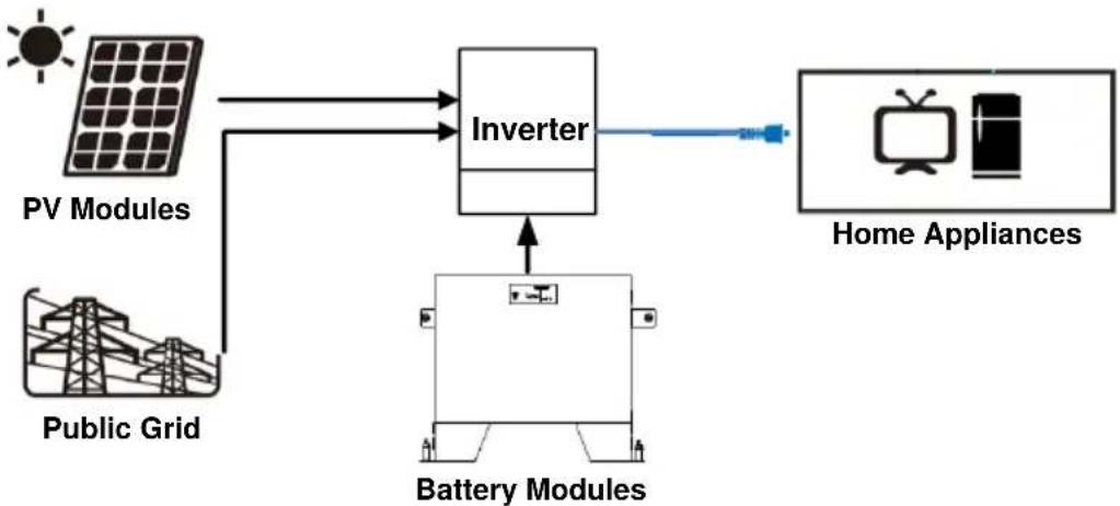
flowchart
graph TD
    A["PV Modules"] --> C["Inverter"]
    B["Public Grid"] --> C["Inverter"]
    C --> D["Battery Modules"]
    D --> E["Home Appliances"]
2.1 Features
- Non-Toxic, non-polluting, and friendly to the environment.
■ LiFeO4 cell material has higher safety performance and long cycle life. - Smart BMS provides protection functions including over-discharge, high temperature, over-charge, and over-current.
- Flexible configuration, multiple battery modules can be easily stacked and added for energy expansion.
■ Working temperature range is from 0^ C to 50^ C with excellent discharge performance and cycle life.
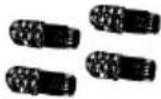
2.2 Package Contents
The packaging is recyclable. Please reuse or dispose it properly.
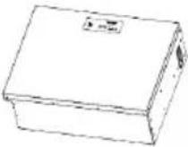 | 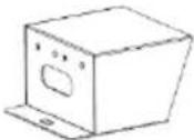 |   | 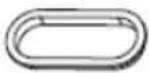 |
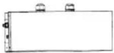
| Battery Module x 1 | Stand Feet x 2 | Fixing Plates for Stand feet: Left x1, Right x1 | SNAP bushing x 2 |
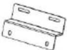
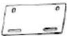
 | 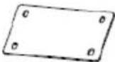 | 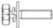 | 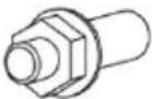 |
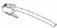
| L-type Brackets x 2 | Fixing Plates x 2 | Screws x 20 | Expansion Bolt M10 x 4 |
 | 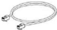 |  |  |
| Battery connectors BAT+ x 2, BAT- x 2 | RJ45 cable x 1 | RJ11 cable x 1 | RJ11 Jumper x 1 |
 |  | ||
| User Manual x 1 | Warranty Card x 1 | ||
PDU module can be purchased separately. Following contents will be included in its separately package:
 |  |
| PDU Module x 1 | Cable Gland x 2 |
2.3 Specifications
| Model | LiFe Battery System 48-100 |
| Capacity | 5120 Wh |
| Battery Cell Technology | Lithium Iron Phosphate |
| Battery Expansion | Up to 10 units |
| Nominal Voltage | 51.2 VDC |
| Rated Capacity | 100 Ah |
| Full Discharge Voltage | 42 VDC |
| Max. ContinuousDischarge Current | 150 A;above 150 A requires the use of PDU |
| Max. Discharge Current | 192 A at 1 min. |
| Discharge Efficiency | 90% |
| Protection | BMS |
| Max. Charge Voltage | 56 V ± 0.1 V |
| Max. Charge Current | Max. 100 A; default 30 A |
| Standard Charge Method | 0.2C CC (Constant Current) charge to FC,CV (Constant Voltage) charge till charge current decline to <0.05C |
| Inner Resistance | ≤20mΩ |
| Battery Life Cycles | 8000 cycles: for 60% DOD at 1C discharging current and 0.2C recharging current with >50% capacity.*2000 cycles: for 90% DOD at 1C discharging current and 0.2C recharging current with >80% capacity.*(*Compared to original capacity) |
| Dimension (D x W x H) | 185 x 540 x 420 mm |
| Dimension with stand feet (D x W x H) | 185 x 540 x 530 mm |
| Net Weight (kg) | 48 |
| Operation Temperature | Charge/ Discharge: 0 °C ~ 50 °COptimum temperature: 10°C ~ 35°C for best life cycles |
| Storage Temperature | -20°C ~ 60 °C;20°C ± 5°C recommended |
| IP Protection | IP 20 |
| Communication | RS485 (RJ45), CAN extension port (RJ11) |
2.4 Product Indicator & Setting
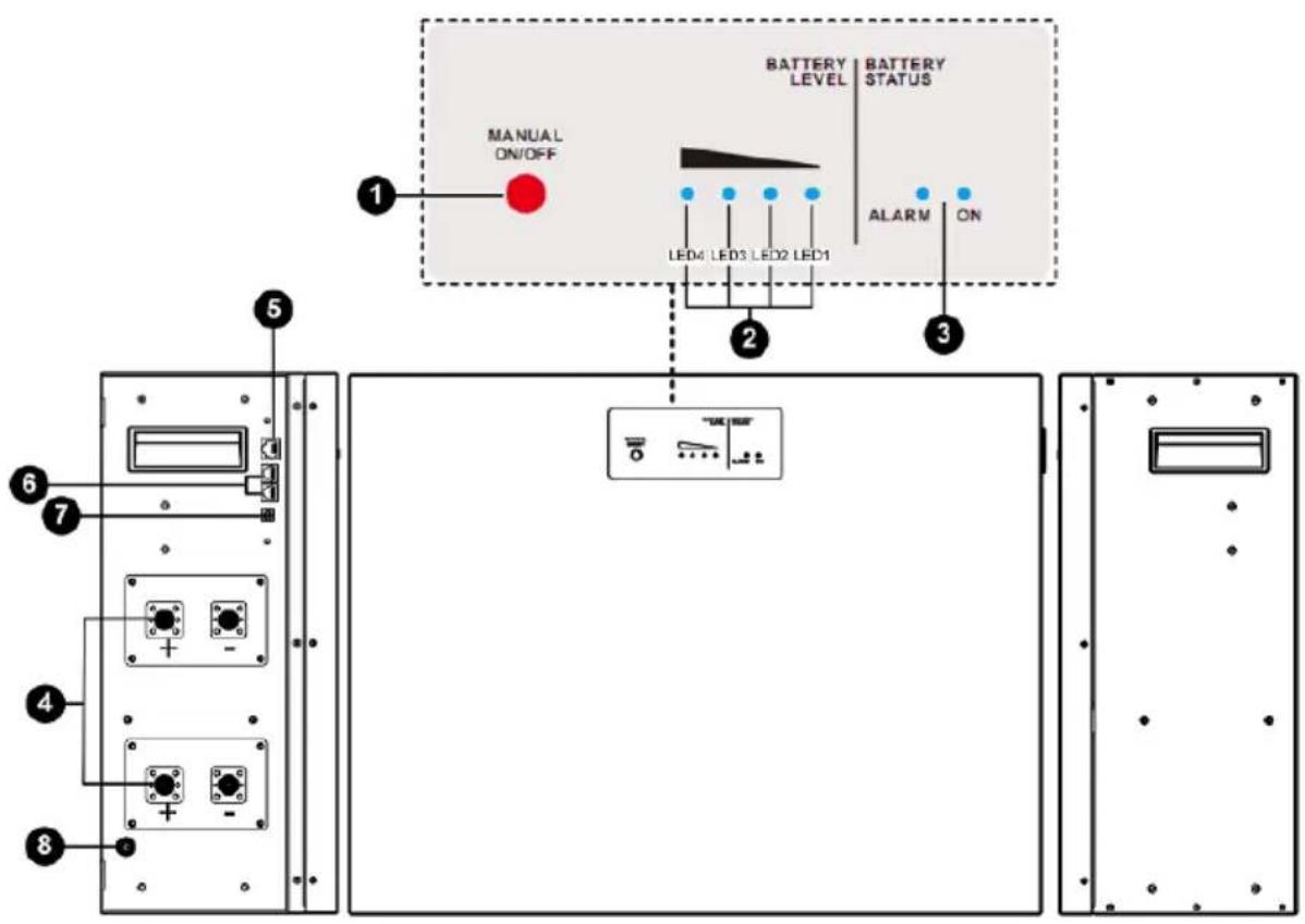
1 Manual power on/off button - to wake up or shut down the battery module.
- If battery module is off, press and hold the button over 5 seconds to turn on the module.
- If battery module is working, press and hold the button for approximately 5 seconds to shut down the module.
2 Battery Level LEDs - Indicates battery level. Please refer to the LED indicator table for the details.
3 Battery Status LEDs - Indicates battery module status. Please refer to the LED indicator table for the details.
LED Indicator:
| Battery Status | Battery Status LEDs | Battery Level LEDs | ||||||
| Status | SOC (Status of Charge) | ON | ALARM | LED1 | LED2 | LED3 | LED4 | |
| Normal Mode | Charging | 0% ~ 25% | ON | OFF | Flash | OFF | OFF | OFF |
| 26% ~ 50% | ON | OFF | ON | Flash | OFF | OFF | ||
| 51% ~ 75% | ON | OFF | ON | ON | Flash | OFF | ||
| 76% ~ 100% | ON | OFF | ON | ON | ON | Flash | ||
| Discharging | 0% ~ 25% | ON | OFF | ON | OFF | OFF | OFF | |
| 26% ~ 50% | ON | OFF | ON | ON | OFF | OFF | ||
| 51% ~ 75% | ON | OFF | ON | ON | ON | OFF | ||
| 76% ~ 100% | ON | OFF | ON | ON | ON | ON | ||
| Alarm mode | Warning | - | OFF | Flash | - | |||
| Fault | - | OFF | ON | - | ||||
| Power Off | - | OFF | OFF | OFF | OFF | OFF | OFF | |
4 External Battery Connector
There are two sets of battery connectors in parallel. Positive terminals are marked in "BAT+" and Negative terminals are marked in "BAT-".
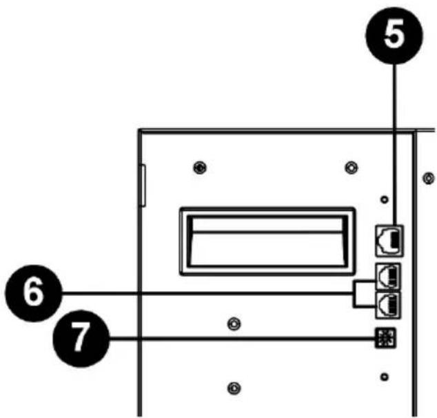
5 RS485 Port (BMS Communication Port)
- Connector type: RJ45
● Function: communication between battery module and inverter module. - Pin Definition:
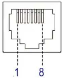 | PIN | Definition |
| 1 | RS485B | |
| 2 | RS485A | |
| 3 | NC2 | |
| 4 | RS485B | |
| 5 | RS485A | |
| 6 | PresentA | |
| 7 | PresentB | |
| 8 | NC1 |
6 Extension Port
- Connector type: RJ11
● Function: BMS signal transmission for battery module and for battery capacity extension in parallel. - Pin Definition
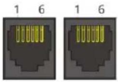 | PIN | Definition |
| 1 | CANH | |
| 2 | CANL | |
| 3 | PresentA | |
| 4 | PresentB | |
| 5 | NC | |
| 6 | NC |
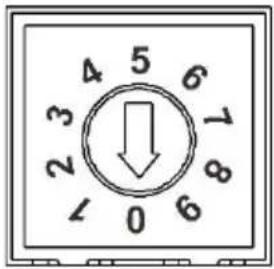
⑦ ID Switch
- ID Switch indicates the unique ID code for each battery module. It's required to assign a unique ID to each battery module for normal operation.
- We can set up the ID code for each battery module by rotating the PIN number on the ID switch. From number 0 to 9, the number can be random; no particular order.
- If more than one battery module in the parallel system, the battery pack connected to the inverter module is the Master battery and the ID code should be set as 0. The ID code of the remaining battery module MUST be unique. Do not set the same number for 2 battery modules in the parallel system.
● Maximum 10 battery modules can be operated in parallel.
 | PIN | Definition |
| 0 | 0x0F | |
| 1 | 0x0E | |
| 2 | 0x0D | |
| 3 | 0x0C | |
| 4 | 0x0B | |
| 5 | 0x0A | |
| 6 | 0x09 | |
| 7 | 0x08 | |
| 8 | 0x07 | |
| 9 | 0x06 |
3. Installation
3.1 Installation Environment
Make sure that the installation environment meets the following conditions:
● The area is completely waterproof.
● The floor is flat and level.
● There are no flammable or explosive materials nearby.
● The ambient temperature is within the range of 0 ^ 50 ^ .
● The temperature and humidity are maintained at a constant level.
● There is minimal dust and dirt in the area.

Caution
If the ambient temperature is out of the operating range, the battery module will stop operate to protect itself. The optimal temperature range for the battery module to operate is 0 °C to 50 °C. Frequent exposure to harsh temperatures may deteriorate the performance and shorten the life cycle of the battery module.
3.2 Mounting the Modules
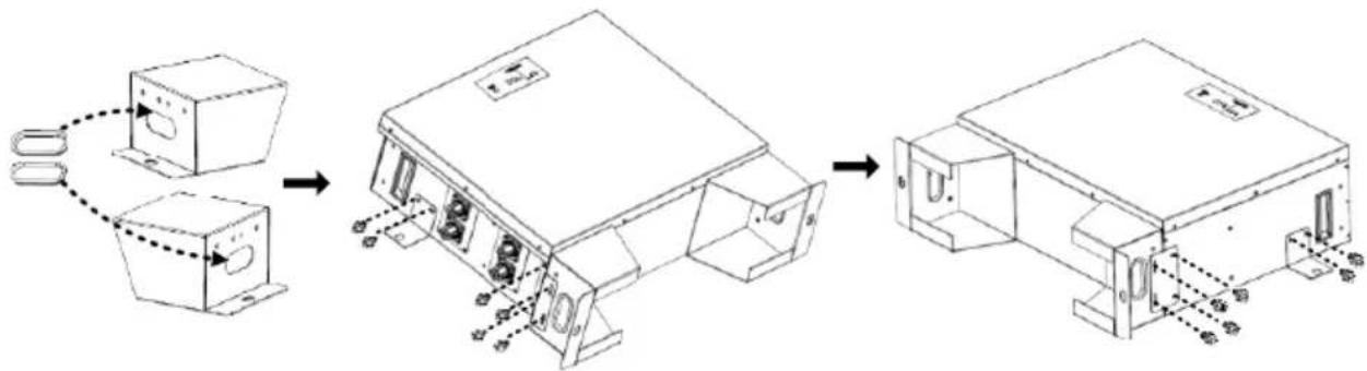
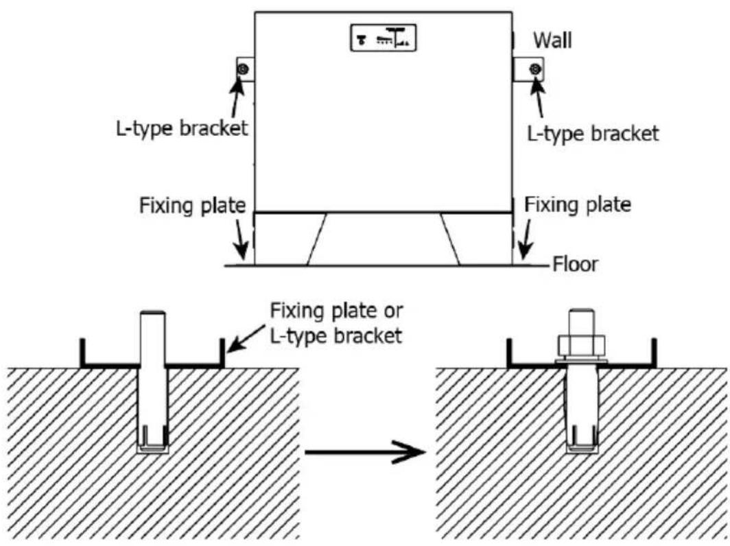
Step 1: Clip two SNAP bushings into the stand feet. Then, fix two fixing plates on the stand feed (both sides) with eight screws. Finally, fix two L-type brackets on the battery module (both sides) with four screws.
flowchart
graph LR
    A["Assembly Setup"] --> B["Product Assembly"]
    B --> C["Packaging Unit"]
    C --> D["Final Packaging"]
Step 2: Install one battery module by following below steps.
(a) Use a 13 mm drill to drill holes about 60 mm deep according to the distance indicated on the below chart. Drill two holes on the
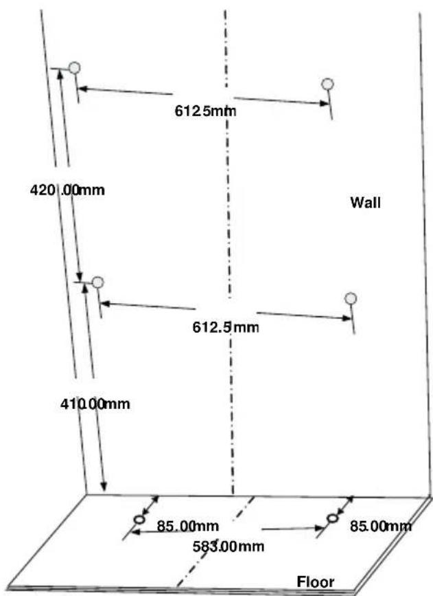
floor first, then drill two holes on the wall. If there is one more battery module to be stacked up, drill two holes at a vertical distance of 420 ~mm .
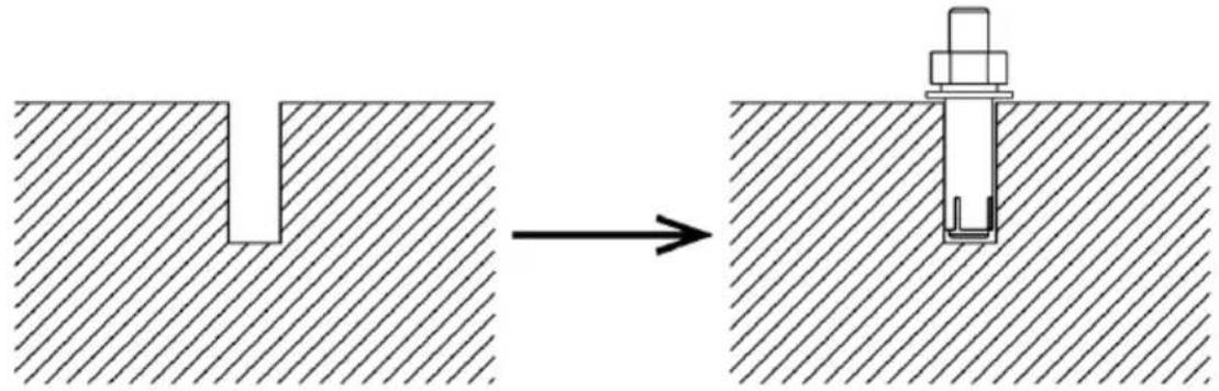
(b) Push four expansion bolts into the 13 mm holes drilled on the previous step.
natural_image
Diagram showing a mechanical assembly process: a cut section before and after a workpiece inserted into a base plate (no text or symbols present)(c) Remove the nut, spring washer and flat washer.
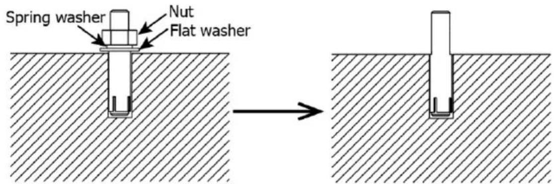
(d) Take assembled battery module (in step 1) and put on the ground. Align the hole on fixing plate with the two expansion bolts on the ground. Align the hole on L-type bracket with two expansion bolts on the wall. Pass through the remaining bolt in the floor and wall. Then, screw back the nut, spring washer, and flat washeremove nut, spring washer and flat washer.
Step 3 (If more than one battery module is connected):
For a single battery module connection, please skip this step! If more than one battery module is connected, please follow the instructions below:
(a) Put the additional battery module on the top of battery module installed on the ground. Make sure they are aligned well.
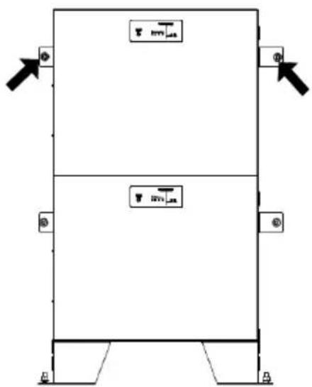
(b) Install one fixing plate to fix two battery modules with four screws as following the picture shown.
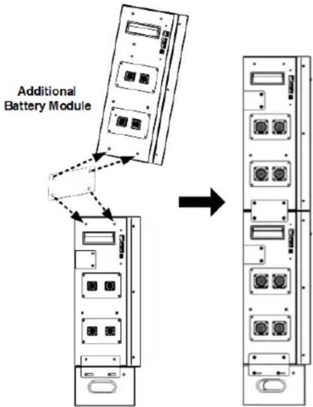
(c) Follow the same procedure as step (b) to fix the other side.
(d) Refer to Step 2, fix the top battery module on the wall with two expansion bolts.
(e) If there are more battery modules installed, repeat steps (a) to (d).
Step 4 (If an optional PDU module is required in the system):
Stack the PDU module on the top of all battery modules. Install two fixing plates on both sides of the modules with eight screws.
natural_image
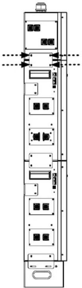
Technical line drawing of a vertical electronic device with multiple ports and connectors (no text or symbols)3.3 Wiring Configuration
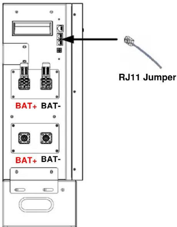
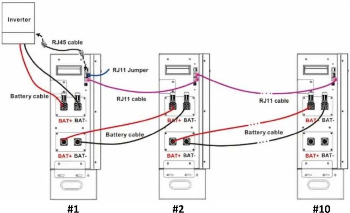
Step 1: Insert the supplied RJ11 jumper into one of the extension ports on the top of the battery module.

Notice
It's required to have RJ11 jumper connected to the single battery module, or to the master battery module when working in parralel with multiple modules for normal operation.
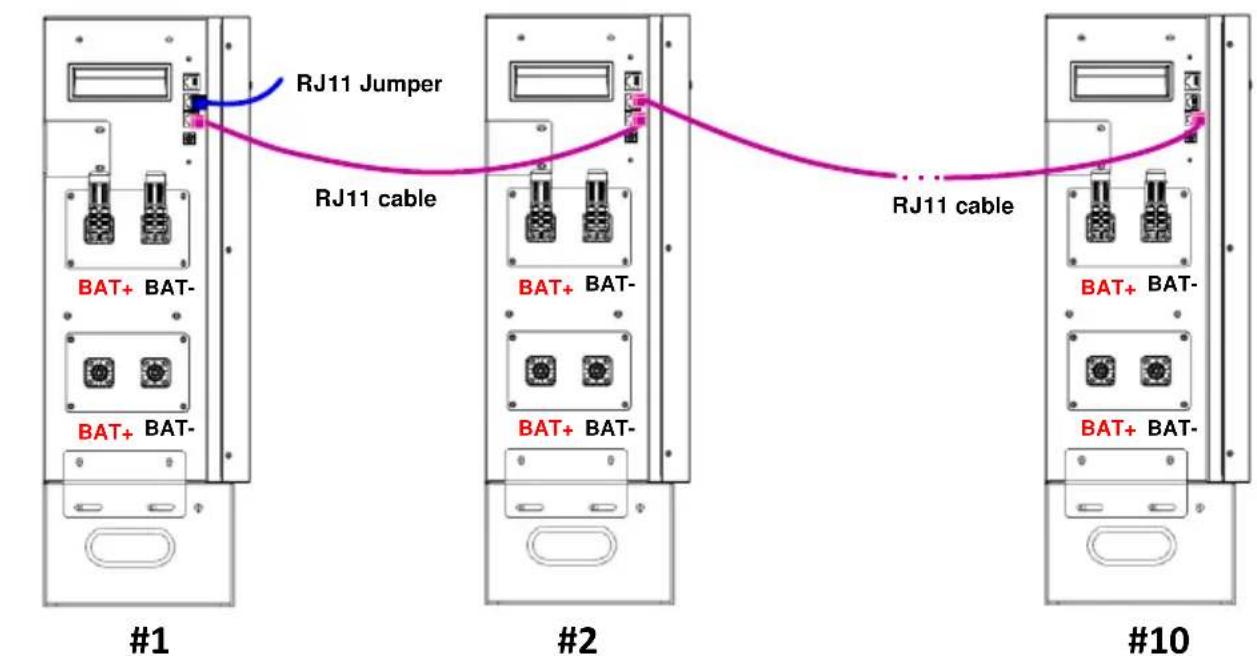
Step 2 (If multiple battery modules are in parallel):
Insert RJ11 cable to connect the extension port of the master battery module. The other end connects to the extension port of the #2 battery module. If there are more battery modules are connected in the system, repeat this step to connect more battery modules.

Caution
Caution: If more than one battery module is connected for capacity expansion, the battery module that is directly connected to the inverter module is defined as the "master battery module". Make sure that the ID number for the master battery module is set to "0".
flowchart
graph TD
    subgraph #1
        A["BAT+ BAT-"] --> B["RJ11 Jumper"]
        C["BAT+ BAT-"] --> B
        B --> D["RJ11 cable"]
    end
    subgraph #2
        E["BAT+ BAT-"] --> F["RJ11 cable"]
        G["BAT+ BAT-"] --> F
        F --> H["RJ11 cable"]
    end
    subgraph #10
        I["BAT+ BAT-"] --> J["RJ11 cable"]
        K["BAT+ BAT-"] --> J
        J --> L["RJ11 cable"]
    end
Master battery module
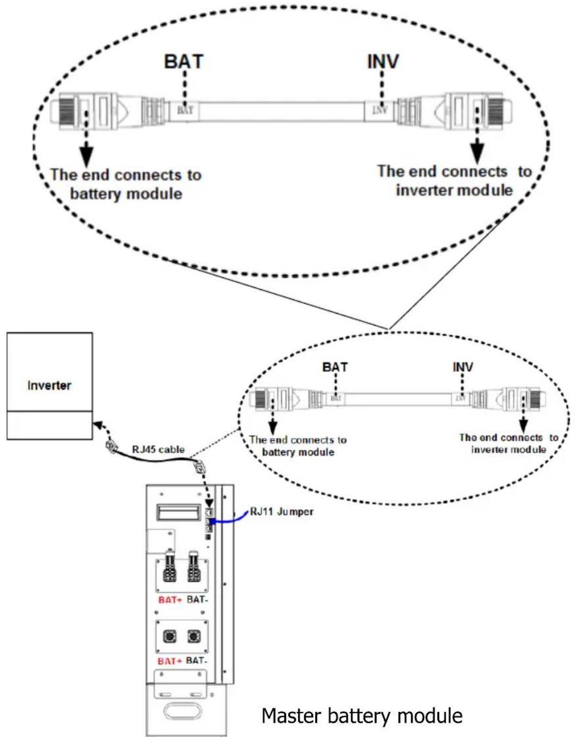
Step 3: Insert the supplied RJ45 cable into the RJ45 communication port on the master battery module. The other end connects to BMS communication port on the inverter module.

Caution
Caution: "BAT" and "INV" are marked on the RJ45 cable. Make sure to connect the battery module and inverter module with correct end.
flowchart
graph TD
    A["Inverter"] -->|RJ45 cable| B["Master battery module"]
    B -->|BJ11 Jumper| C["BJ11 + BAT-"]
    C --> D["BAT"]
    D --> E["INV"]
    E --> F["The end connects to battery module"]
    F --> G["Master battery module"]
    style A fill:#f9f,stroke:#333
    style B fill:#ccf,stroke:#333
    style C fill:#cfc,stroke:#333
    style D fill:#fcc,stroke:#333
    style E fill:#cff,stroke:#333
    style F fill:#ffc,stroke:#333
    style G fill:#fcf,stroke:#333
Step 4: Please follow below steps to prepare battery cable with supplied external battery connectors. The cable length should be prepared based on the real distance between battery module and inverter module.
The recommended cable size is listed as below:
| Wire Size | Cable mm^2 |
| 1*4AWG | 25 |
(a) Loosen and disassemble the plug of the supplied battery connector.
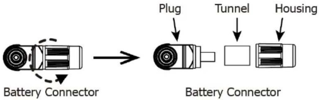
flowchart
graph LR
    A["Battery Connector"] --> B["Battery Connector"]
    B --> C["Plug"]
    B --> D["Tunnel"]
    B --> E["Housing"]
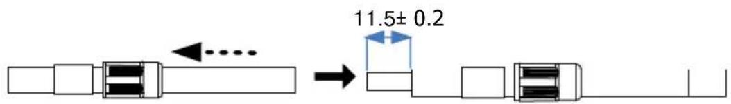
(b) Insert the battery cable through the tunnel and housing, and strip battery cable 11.5 ± 0.2 ~mm .
(c) Crimp the cable and the plug with a proper crimping tool (ex. hydraulic clamp) together into a hexagon shape as shown in below chart. Then, move the housing toward plug and tighten them.
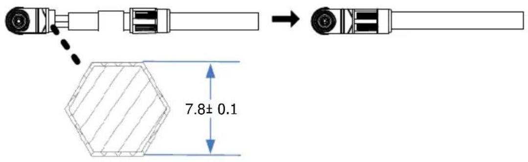
(d) Use battery cable to connect the battery module and inverter module. Make sure the polarity of battery module are correctly connected.
RED connector to the positive terminal (+) BLACK connector to the negative terminal (-)
If more than one battery modules are connected, use battery cable to connect master battery module and remaining battery module one by one.
flowchart
graph TD
    Inverter["Inverter"] --> RJ45["RJ45 cable"]
    RJ45 --> RJ11J["Jumper"]
    RJ11J --> RJ11C["RJ11 cable"]
    RJ11C --> RJ11D["RJ11 cable"]
    RJ11D --> RJ11E["Battery cable"]
    RJ11E --> RJ11F["Battery cable"]
    RJ11F --> RJ11G["Battery cable"]
    RJ11G --> RJ11H["Battery cable"]
    RJ11H --> RJ11I["Battery cable"]
    RJ11I --> RJ11J["Battery cable"]
    RJ11J --> RJ11K["Battery cable"]
    RJ11K --> RJ11L["Battery cable"]
    RJ11L --> RJ11M["Battery cable"]
    RJ11M --> RJ11N["Battery cable"]
    RJ11N --> RJ11O["Battery cable"]
    RJ11O --> RJ11P["Battery cable"]
    RJ11P --> RJ11Q["Battery cable"]
    RJ11Q --> RJ11R["Battery cable"]
    RJ11R --> RJ11S["Battery cable"]
    RJ11S --> RJ11T["Battery cable"]
    RJ11T --> RJ11U["Battery cable"]
    RJ11U --> RJ11V["Battery cable"]
    RJ11V --> RJ11W["Battery cable"]
    RJ11W --> RJ11X["Battery cable"]
    RJ11X --> RJ11Y["Battery cable"]
    RJ11Y --> RJ11Z["Battery cable"]
    RJ11Z --> RJ11A["Battery cable"]
    RJ11A --> RJ11B["Battery cable"]
    RJ11B --> RJ11C["Battery cable"]
    RJ11C --> RJ11D["Battery cable"]
    RJ11D --> RJ11E["Battery cable"]
    RJ11E --> RJ11F["Battery cable"]
    RJ11F --> RJ11G["Battery cable"]
    RJ11G --> RJ11H["Battery cable"]
    RJ11H --> RJ11I["Battery cable"]
    RJ11I --> RJ11J["Battery cable"]
    RJ11J --> RJ11K["Battery cable"]
Master battery module
(e) After connecting all cables, the battery modules are ready for DC output.
3.4 Wiring Diagrams of Diverse Applications
(1) Single battery module connection with a max 150A current wiring:
(suitable for ≤ 6KW Inverter)
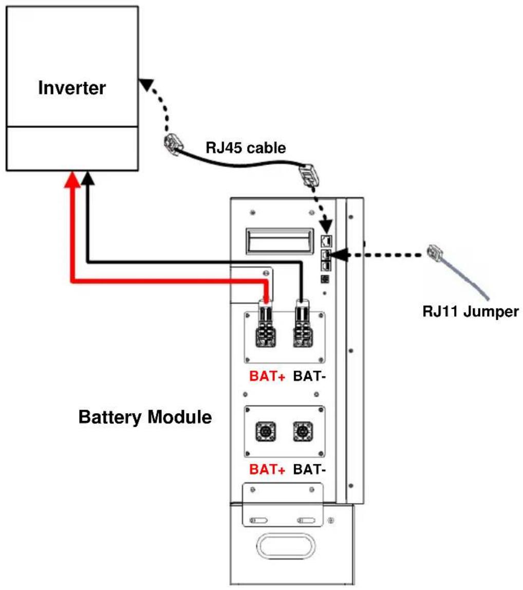
flowchart
graph TD
    A["Inverter"] -->|RJ45 cable| B["Battery Module"]
    B --> C["RJ11 Jumper"]
    B --> D["BAT+ BAT-"]
    B --> E["BAT+ BAT-"]
    style A fill:#f9f,stroke:#333
    style B fill:#ccf,stroke:#333
    style C stroke-dasharray: 5 5
    style D stroke-dasharray: 5 5
    style E stroke-dasharray: 5 5
(2) Two-battery module connection for a longer backup time with a max 150A current wiring:
(suitable for ≤ 6KW Inverter)
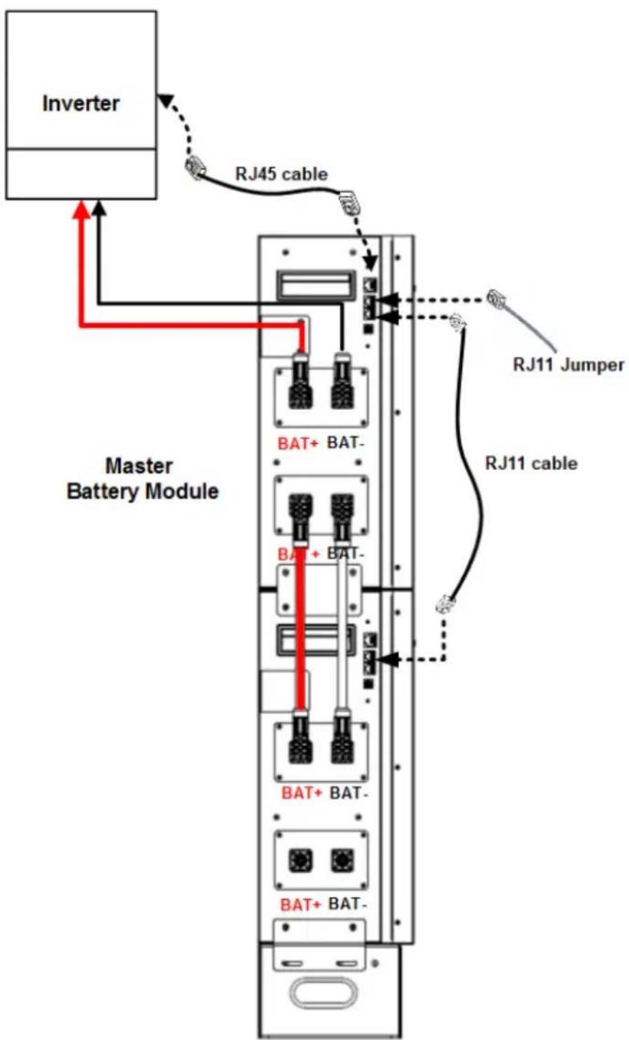
flowchart
graph TD
    A["Inverter"] -->|RJ45 cable| B["Master Battery Module"]
    B -->|RJ11 Jumper| C["RJ11 cable"]
    B --> D["BAT+ BAT-"]
    B --> E["BAT+ BAT-"]
    B --> F["BAT+ BAT-"]
    B --> G["BAT+ BAT-"]
    style A fill:#f9f,stroke:#333
    style B fill:#ccf,stroke:#333
    style C fill:#cfc,stroke:#333
    style D fill:#fcc,stroke:#333
    style E fill:#fcc,stroke:#333
    style F fill:#fcc,stroke:#333
    style G fill:#fcc,stroke:#333
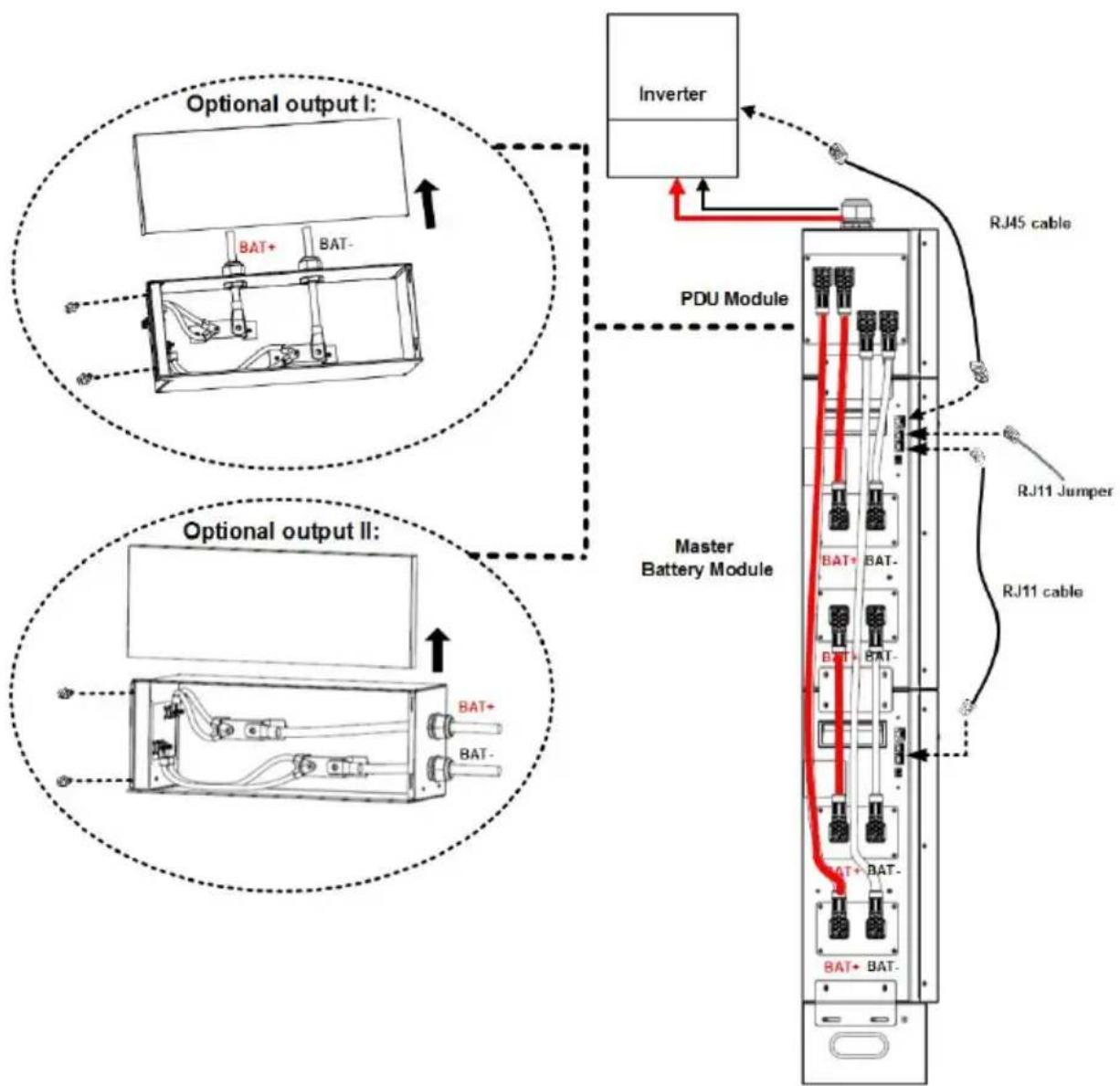
(3) Two-battery module connection for a larger-capacity Inverter:
(suitable for > 6KW Inverter)

Caution
Caution: PDU module is required for combining battery pack current!
flowchart
graph TD
    A["Optional output I: Inverter"] --> B["PDU Module"]
    B --> C["Master Battery Module"]
    C --> D["RJ11 Jumper"]
    C --> E["RJ11 cable"]
    F["Optional output II: Inverter"] --> G["Master Battery Module"]
    G --> H["RJ11 Jumper"]
    G --> I["RJ11 cable"]
    style A fill:#f9f,stroke:#333
    style F fill:#f9f,stroke:#333
    style G fill:#ccf,stroke:#333
    style H fill:#cfc,stroke:#333
    style I fill:#fcc,stroke:#333
Enlarged diagram from p.26
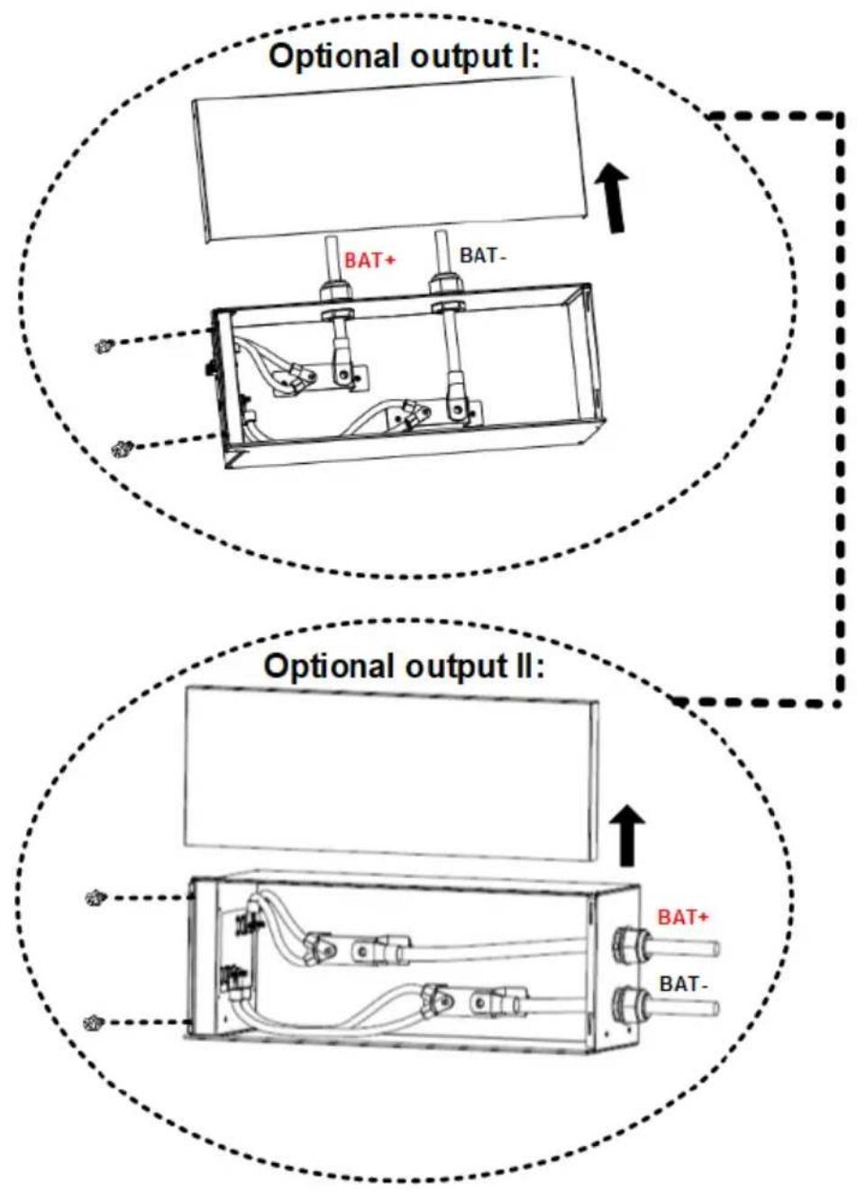
Enlarged diagram from p.26
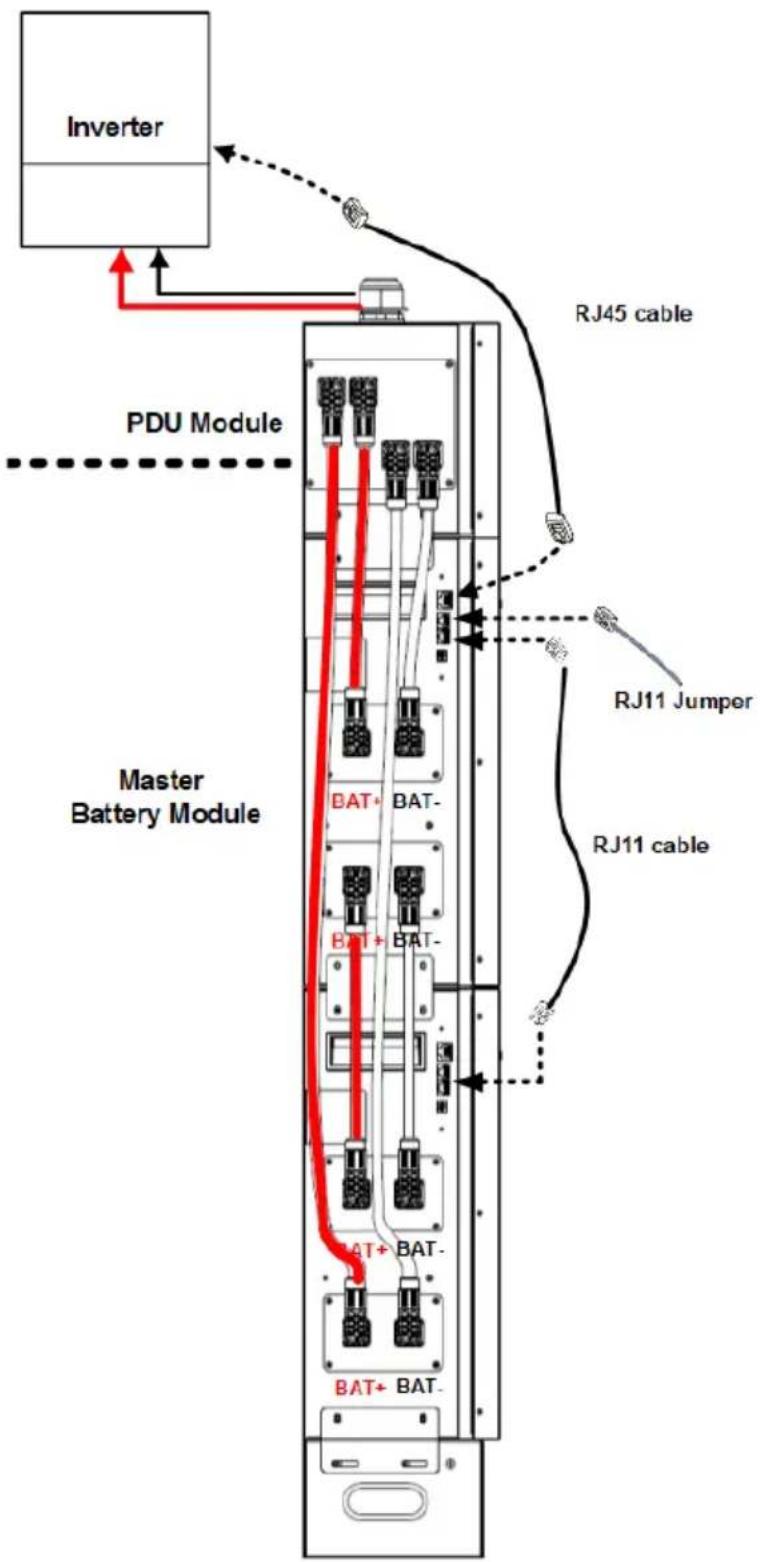
flowchart
graph TD
    A["Inverter"] --> B["PDU Module"]
    B --> C["Master Battery Module"]
    C --> D["RJ45 cable"]
    C --> E["RJ11 Jumper"]
    C --> F["RJ11 cable"]
    C --> G["BAT+ BAT-"]
    C --> H["BAT+ BAT-"]
    C --> I["BAT+ BAT-"]
    style A fill:#f9f,stroke:#333
    style B fill:#ccf,stroke:#333
    style C fill:#cfc,stroke:#333
    style D fill:#fcc,stroke:#333
    style E fill:#fcc,stroke:#333
    style F fill:#fcc,stroke:#333
    style G fill:#cff,stroke:#333
    style H fill:#cff,stroke:#333
    style I fill:#cff,stroke:#333
(4) Multiple battery modules in parallel for large-capacity inverter with a longer backup time:
(suitable for > 6KW Inverter)

Caution
Caution: PDU module is required for combining battery pack current!
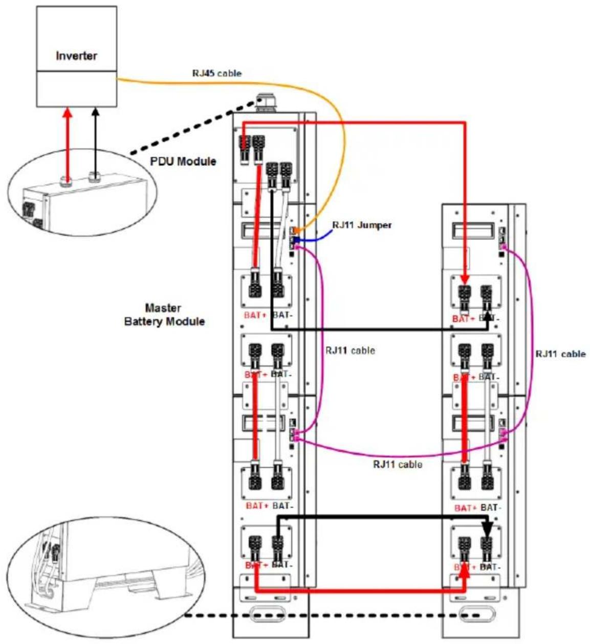
flowchart
graph TD
    A["Inverter"] -->|RJ45 cable| B["PDU Module"]
    B --> C["Master Battery Module"]
    C --> D["RJ11 Jumper"]
    D --> E["RJ11 cable"]
    E --> F["RJ11 cable"]
    F --> G["BATT + BAT-"]
    G --> H["BATT + BAT-"]
    H --> I["BATT + BAT-"]
    I --> J["BATT + BAT-"]
    J --> K["BATT + BAT-"]
    K --> L["BATT + BAT-"]
    L --> M["BATT + BAT-"]
    M --> N["BATT + BAT-"]
    N --> O["BATT + BAT-"]
    O --> P["BATT + BAT-"]
    P --> Q["BATT + BAT-"]
    Q --> R["BATT + BAT-"]
    R --> S["BATT + BAT-"]
    S --> T["BATT + BAT-"]
    T --> U["BATT + BAT-"]
    U --> V["BATT + BAT-"]
    V --> W["BATT + BAT-"]
    W --> X["BATT + BAT-"]
    X --> Y["BATT + BAT-"]
    Y --> Z["BATT + BAT-"]
    Z --> AA["BATT + BAT-"]
    AA --> AB["BATT + BAT-"]
    AB --> AC["BATT + BAT-"]
    AC --> AD["BATT + BAT-"]
    AD --> AE["BATT + BAT-"]
4. Start-Up/Shut-Off the Battery Module
4.1 Start up the battery module
(a) When battery module is in the shutdown mode, press manual ON/OFF button for over 5 seconds.
(b) Or, simply turn on the inverter module which is connected to a battery module already. The battery module will be automatically turned on.
*If the manual button cannot be approached, just simply turn on the Inverter module. The battery module will be automatically turned on.
4.2 Shut-off the battery module
When battery module is in the operating mode, press manual ON/OFF button for 5 seconds.
5. Trouble Shooting
Use the table below to solve minor installation and operation problems.
| Situation | Fault Event Description | Solution |
| Battery pack no output | RJ11 jumper is missing. | Re-check if the RJ11 jumper is connected well. |
| Battery cannot discharge | Same ID code set in multiple battery packs. | Re-set each battery with different ID codes. |
| Under-voltage protection. | Charge battery. | |
| Protection against over-temperature or under-temperature (cell temperature is lower than -20 °C or higher than 80 °C). | Regulate cell temperature in the range of -20 °C to 60°C for discharge. | |
| Protection against over current. | Remove some non-critical load and charge battery. | |
| Battery output is short circuited. | Relieve short circuit and charge battery. | |
| System failure detected. | Shut down system and call maintenance service. | |
| In parallel battery packs, CAN communication lost and “parallel imbalance” occur on slave battery. | Ensure communication wires are all correctly connected well. | |
| Battery cannot charge | Protection against over current. | Reduce the output current of power module. |
| Protection against over-temperature or under- temperature (cell temperature is lower than 0 °C or higher than 60 °C). | Regulate cell temperature in the range of 0°C to 50 °C for charge. | |
| System failure detected. | Shut down system and call maintenance service. | |
| Communication failure is detected | Communication cable is not connected well. | Check if communication cable is firmly connected. |
| Communication ID switch conflict. | Check the parallel batteries ID switch setting and correct them. | |
| System failure detected. | Shut down system and call maintenance service. |
PowerWalker
natural_image
Exterior view of a white power heater appliance with control panel and indicator lights (no visible text or symbols on the device itself)LiFe-Batterie-System 48-100
Scan me!
For additional information
Product Links

Product Datasheet
Version: 02
Date: 2023-2-01
natural_image
Diagram showing a mechanical assembly process: a V-shaped cutout on a hatched surface before and after a bolt installation (no text or symbols)natural_image
Technical line drawing of a vertical electrical cabinet or enclosure with multiple compartments and control panels (no text or labels)3.3 Konfiguration der Verdrahtung
flowchart
graph TD
    A["Battery Connector"] --> B["Plug"]
    A --> C["Tunnel"]
    A --> D["Housing"]
natural_image
Exterior view of a white industrial power unit with 'PowerWorker' branding and control panel (no readable text beyond branding)LiFe Battery System 48-100
Scan me! For
Product Links

Product Datasheet
Version: 02
Date: 2023-2-01
flowchart
graph LR
    A["Assembly Setup"] --> B["Product Assembly"]
    B --> C["Packaging Unit"]
    C --> D["Final Packaging"]
natural_image
Diagram showing a mechanical assembly process: a cut section before and after a bolted joint (no text or symbols present)flowchart
graph LR
    A["Battery Connector"] --> B["Plug"]
    A --> C["Tunnel"]
    A --> D["Housing"]
natural_image
Exterior view of a white power wall heater unit with control panel and indicator lights (no visible text or symbols on the device itself)For additional information:
Product Links
Product Datasheet

Version: 02
Date: 2023-2-01
Conventions relatives aux symboles
2. Introduction......6
3. Installation....14
5 Port RS485 (port de communication BMS)
natural_image
Diagram showing a mechanical assembly or mounting process with hatched material and a bolted component, no text or symbols present.natural_image
Technical line drawing of a vertical electrical cabinet or rack unit with multiple compartments and mounting points (no text or symbols)flowchart
graph LR
    A["Battery Connector"] --> B["Plug"]
    A --> C["Tunnel"]
    A --> D["Housing"]
natural_image
Exterior view of a white power heater appliance with black base and control panel (no visible text or symbols)LiFe Battery System 48-100
Scan me! For additional information
Product Links
Product Datasheet
Version: 02
Date: 2023-2-01
flowchart
graph LR
    A["Mounting Box"] --> B["Assembly Unit"]
    B --> C["Final Assembly Unit"]
natural_image
Diagram showing a mechanical assembly process: a cut section on the left and a bolt inserted into a housing on the right (no text or symbols)natural_image
Pure electrical circuit lines without any symbolsflowchart
graph LR
    A["Battery Connector"] --> B["Plug"]
    A --> C["Tunnel"]
    A --> D["Housing"]