VFD 600 - Uninterruptible power supply PowerWalker - Free user manual and instructions
Find the device manual for free VFD 600 PowerWalker in PDF.

User questions about VFD 600 PowerWalker
0 question about this device. Answer the ones you know or ask your own.
Ask a new question about this device
Download the instructions for your Uninterruptible power supply in PDF format for free! Find your manual VFD 600 - PowerWalker and take your electronic device back in hand. On this page are published all the documents necessary for the use of your device. VFD 600 by PowerWalker.
USER MANUAL VFD 600 PowerWalker
natural_image
Black electronic device with ventilation slots and a logo (no visible text or symbols on body)Quick Start Guide
EN/DE/FR/ES/IT/GR/RU/UA/FI/HR/PL/PT/RO/SE
EN
IMPORTANT SAFETY INSTRUCTIONS
EN
SAVE THESE INSTRUCTIONS – This manual contains important instructions for models PowerWalker VFD 400/600/800 that should be followed during installation and maintenance of the UPS and batteries.
- This product is specially designed for PCs and it is not recommended for use in any life-supporting system and other specific important equipment.
- This equipment can be operated by any individual with no previous training.
- Do not plug household appliances such as hair dryers to UPS receptacles.
- This unit intended for installation in a controlled environment (temperature controlled, indoor area free of conductive contaminants). Avoid installing the UPS in locations where there is standing or running water, or excessive humidity.
- Risk of electric shock, do not remove cover. No user serviceable parts inside. Refer servicing to qualified service personnel.
- The utility power outlet shall be near the equipment and easily accessible. To isolate UPS from AC input, remove the plug from the utility power outlet.
- If UPS is to be stored for a long time, it is recommended to recharge the batteries (by connecting the utility power to UPS, switch "ON"), once a month for 24 hours to avoid a full battery discharge.
- Please do not use the UPS in excess of the rated load capacity.
- The UPS contains one/two large-capacity batteries. So the shell shall not be opened, otherwise such dangers as electric shock will be caused. If any internal overhaul or replacement of the battery is required, please contact the distributor.
- The internal short circuiting of the UPS will lead to dangers such as electric shock or fire, therefore, no water containers (such as a water glass) shall be placed on the top of the UPS so as to avoid such dangers as electric shock.
- Do not dispose of battery or batteries in a fire. The battery may explode.
- Do not open or mutilate the battery or batteries. Released electrolyte is harmful to the skin and eyes. It may be toxic.
- Icon on the rating label stands for phase symbol.
- A battery can present a risk of electrical shock and high short circuit current. The following precautions should be observed when working on batteries:
- Remove watches, rings, or other metal objects from the hand.
• Use tools with insulated handles.
- Servicing of batteries should be performed or supervised by personnel knowledgeable of batteries and the required precautions. Keep unauthorized personnel away from batteries.
- When replacing batteries, replace with the same type and number of the sealed lead-acid batteries.
• The maximum ambient temperature rating is 40^ C.
- This pluggable type A equipment with battery already installed by the supplier is operator installable and may be operated by laymen.
- During the installation of this equipment it should be assured that the sum of the leakage currents of the UPS and the connected loads does not exceed 3.5mA.
- Attention, hazardous through electric shock. Also with disconnection of this unit from the mains, hazardous voltage still may be accessible through supply from battery. The battery supply should be therefore disconnected in the plus and minus pole of the battery when maintenance or service work inside the UPS is necessary.
- The mains socket outlet that supplies the UPS shall be installed near the UPS and shall be easily accessible.
- In case smoke is found coming out from the device, please cut off the power supply quickly and contact the distributor.
- Do not keep or use this product in any of the following environments:
○Any area with combustible gas, corrosive substance or heavy dust.
○Any area with extraordinarily high or low temperature (above 40^ C or below 0^ C) and humidity of more than 90%.
○Any area exposed to direct sunshine or near any heating apparatus.
○Any area with serious vibrations.
oOutdoor.
- In the event that there is fire occurring in the vicinity, please use dry-power extinguishers. The use of liquid extinguishers may give rise to the danger of electric shock.
This product complies with the safety and environmental regulations in EU.
If the time arises to throw away your product, please recycle all the components possible. Batteries and rechargeable batteries are not to be disposed in your domestic waste! Please recycle them at your local recycling point. Together we can help to protect the environment.

1. Product Introduction
EN
The PowerWalker VFD series provides comprehensive protection in a small and economic package. The UPS is more compact and offers greater comprehensive power protection against surges and spikes. This UPS will continue providing stable power to connected equipment and enable to shutdown PC safely during power failure. Its embedded microprocessor controller guarantees high reliability and it's perfect for any home or small office application.
Features:
- Compact size with stand and mounting flexibility
• Excellent microprocessor control guarantees high reliability
• Auto restart while AC is recovering - Simulated sine wave
- Cold start function
• Full protection: Discharge, overcharge, short circuit, and thermal Protection
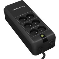
2. Package Contents
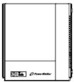
You should have received the following items inside of package:
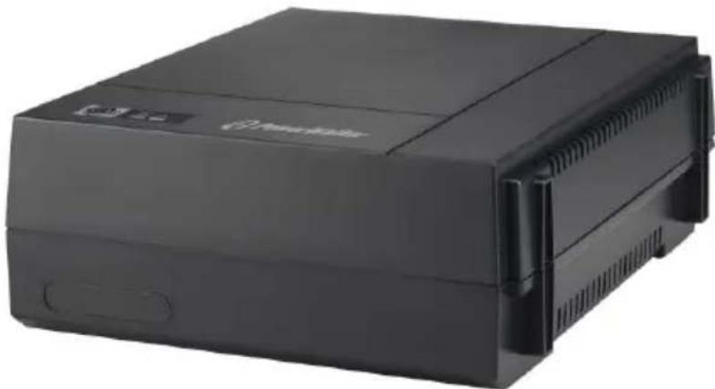
natural_image
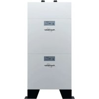
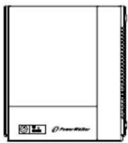
Front view of a rectangular electronic device with a small icon on the side panel (no visible text or symbols)UPS Unit

Quick Start Guide
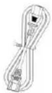
Input Power cord
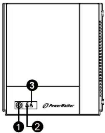
3. Product Overview
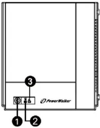
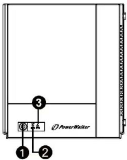
Front Panel:
EN
① Power Switch
② UPS status indicator
3 Fault/Battery status indicator
(Check the Indicator & Alarm Table for the details.)
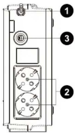
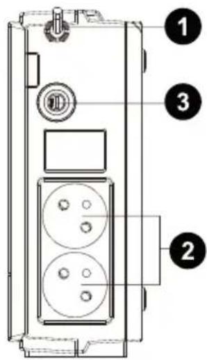
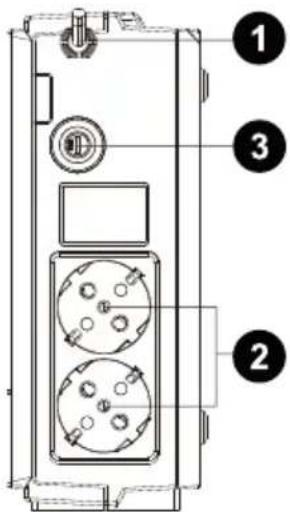
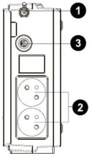
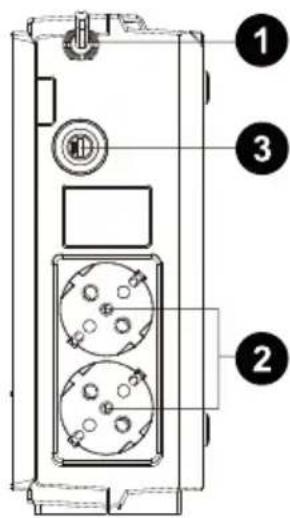
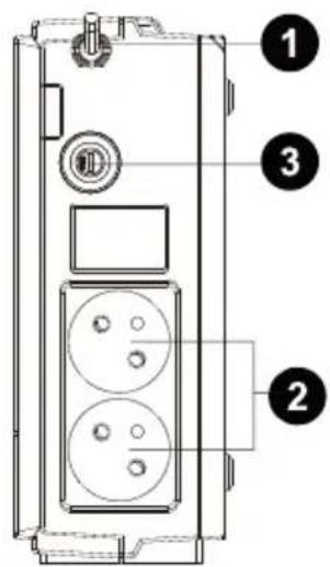
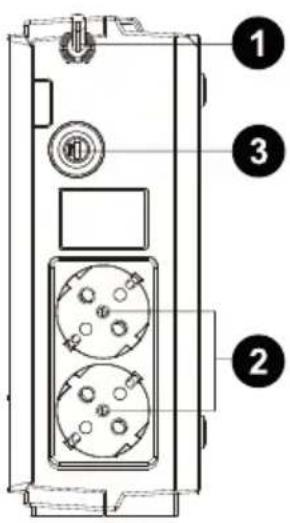
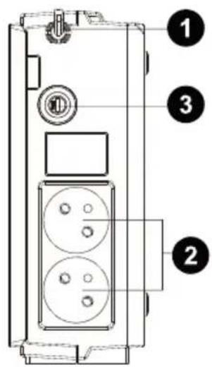
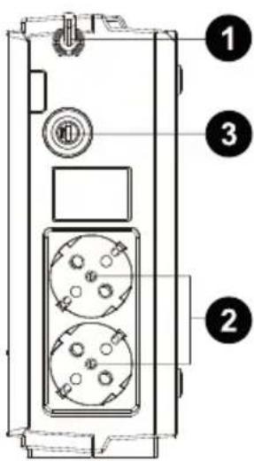
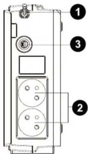
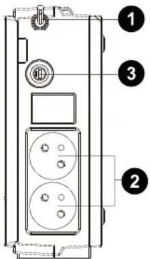
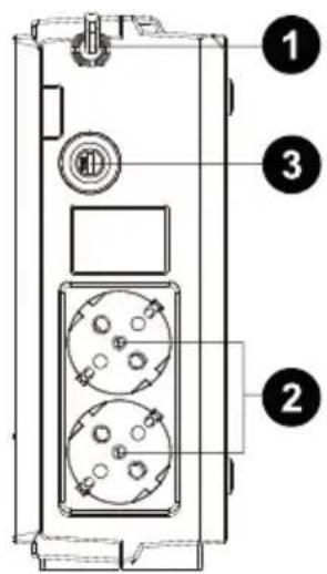
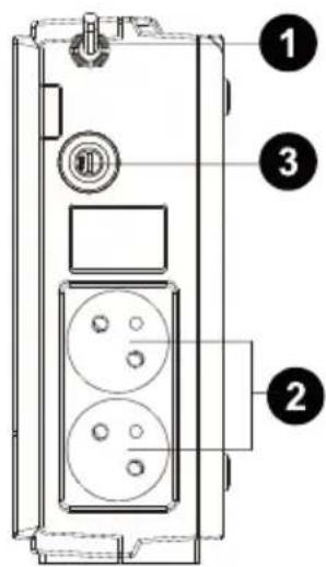
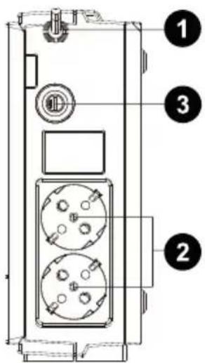
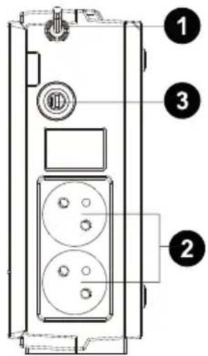
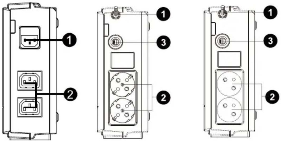
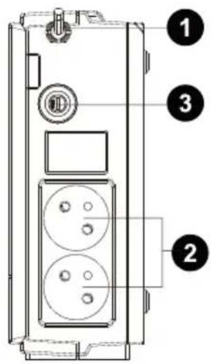
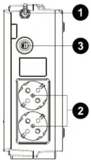
Back Panel:
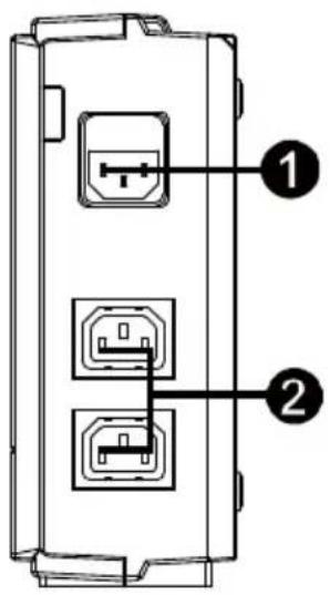
IEC Type
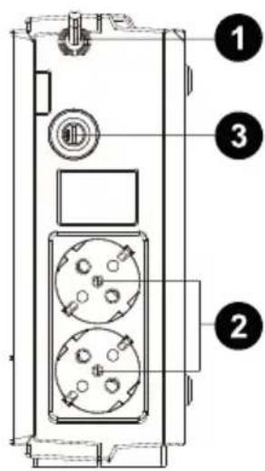
Schuko Type
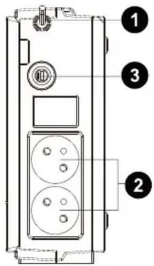
French Type
① AC input
② Output receptacles
③ Circuit breaker
4. Installation and Initial Startup

NOTE: Before installation, please inspect the unit. Be sure that nothing inside the package is damaged.

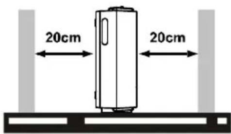
I: Placement & Storage Conditions
Install the UPS in a protected area that is free of excessive dust and has adequate air flow. Please place the UPS away from other units at least 20 cm to avoid interference. Do NOT operate the UPS where the temperature and humidity is outside the specific limits. (Please check the specs for the limitations.)

II: Connect to Utility and Charge
Before initial use, please plug in the AC input cord to the wall outlet and turn on the UPS for charging. For the best results, suggest to charge the battery at least 8 hours before initial use.

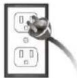
8 hours
III: Connect the Loads
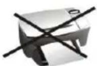
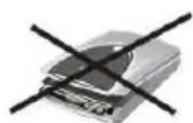
Plug in the loads to output receptacles on the rear panel of the UPS. Simply turn on the power switch of UPS unit, then devices connected to the UPS will be protected by UPS unit.

NEVER NEVER connect a laser printer or scanner to the UPS unit. This may cause the damage of the unit.
VI: Turn On/Off the Unit
Turn on the UPS unit by pressing the power switch. Turn off the UPS unit by pressing again the power switch.
5. Indicators & Alarm Table for Operation
| Conditions | Visual Indicator | Alarm |
| AC Mode | Green LED lighting | Off |
| Battery Mode | Green LED flashing every 10 seconds | Sounding every 10 seconds |
| Low battery at battery mode | Green LED flashing every second and Red LED lighting | Sounding every second |
| Fault | Red LED lighting | Continuously sounding |
| Alarm for over-temperature protection | Red LED flashing every 0.5 seconds | Off |
6. Trouble Shooting
Use the table below to solve minor problems.
| Problem | Possible Cause | Solutions |
| No LED display on the front panel. | Low battery. | Charge the UPS at least 8 hours. |
| Battery fault. | Replace the battery with the same type of battery. | |
| The UPS is not turned on. | Press the power switch again to turn on the UPS. | |
| Alarm continuously sounds when the mains is normal. | The UPS is overload. | Remove some loads first. Before reconnecting equipment, please verify that the load matches the UPS capability specified in the specs. |
| UPS fault | Return the unit to the service center. | |
| Alarm sounds every 2 seconds when the mains is normal. | Battery defect. | Replace the battery with the same type of battery. |
| Charging board is damaged. | Return the unit to the service center. | |
| When power fails, back-up time is shorten. | The UPS is overload. | Remove some critical load. |
| Battery voltage is too low. | Charge the UPS at least 8 hours. | |
| Battery defect. It might be due to high temperature operation environment, or improper operation to battery. | Replace the battery with the same type of battery. | |
| The mains is normal but LED is flashing. | Power cord is loose. | Reconnect the power cord properly. |
EN
7. Specifications
| Model | Power Walker VFD400 | Power Walker VFD600 | Power Walker VFD800 |
| CAPACITY | 400 VA / 240 W | 600 VA / 360 W | 800 VA / 480 W |
| INPUT | |||
| Voltage | 230 VAC | ||
| Voltage Range | 180~270 VAC | ||
| Frequency | 50 Hz | ||
| OUTPUT | |||
| Voltage Regulation | +/-10% | ||
| Transfer Time | Typical 2-6 ms | ||
| Waveform | Simulated Sine Wave | ||
| BATTERY | |||
| Type & Number | 12 V / 4.5 AH x 1 | 12 V / 7 AH x 1 | 12 V / 9 AH x 1 |
| Charging Time | 8 hours recover to 90% capacity | ||
| PHYSICAL | |||
| Dimension(DxWxH) | 228 x 82.5 x 207 mm (@ vertically stand) | ||
| Net Weight (kgs) | 2.2 | 2.7 | 3.1 |
| Environment | |||
| Humidity | 0-90 % | ||
| Temperature | 0-40°C (non-condensing) | ||
Off Line USV
PowerWalker VFD 400
PowerWalker VFD 600
PowerWalker VFD 800
natural_image
Black electronic device with ventilation slots and a logo (no visible text or symbols on body)Schnellanleitung
EN/DE/FR/ES/IT/GR/RU/UA/FI/HR/PL/PT/RO/SE
DE
1. Einführung
DE
USV-Gerät

Kurzanleitung
natural_image
Two grayscale icons with crossed black lines, no text or symbols presentnatural_image
Black industrial electronic device with ventilation slots and a logo (no visible text or symbols on body)EN/DE/FR/ES/IT/GR/RU/UA/FI/HR/PL/PT/RO/SE
INSTRUCTIONS DE SÉCURITÉ IMPORTANTES
FR
Onduleur
natural_image
Black electronic device with ventilation slots and a logo, no visible text or symbols on the body.EN/DE/FR/ES/IT/GR/RU/UA/FI/HR/PL/PT/RO/SE
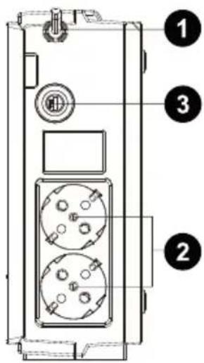
1. Introducción
ES
Unidad SAI
① Entrada CA con fusible
② Enchufes de salida
③ Cortacircuito
natural_image
Black electronic device with ventilation slots and a logo (no visible text or symbols on body)EN/DE/FR/ES/IT/GR/RU/UA/FI/HR/PL/PT/RO/SE
IMPORTANTI ISTRUZIONI PER LA SICUREZZA
IT
1. Introduzione
IT
Unità UPS
natural_image
Two identical 3D-rendered objects with black X marks, no text or symbols presentnatural_image
Black industrial electronic device with ventilation slots and a logo (no visible text or symbols on body)ΕΓΧΕΙΡΙΔΙΟ ΧΡΗΣΤΗ
EN/DE/FR/ES/IT/GR/RU/UA/FI/HR/PL/PT/RO/SE
GR
natural_image
Two identical 3D-rendered objects with black X marks, no text or symbols presentnatural_image
Black electronic device with ventilation slots and a logo (no visible text or symbols on body)EN/DE/FR/ES/IT/GR/RU/UA/FI/HR/PL/PT/RO/SE
RU
Блок ИБП

Краткое руководство
natural_image
Black electronic device with ventilation slots and a logo (no visible text or symbols on body)EN/DE/FR/ES/IT/GR/RU/UA/FI/HR/PL/PT/RO/SE
UA
- Compact size with stand and mounting flexibility
• Excellent microprocessor control guarantees high reliability
• Auto restart while AC is recovering
• Simulated sine wave - Cold start function
• Full protection: Discharge, overcharge, short circuit, and thermal Protection
2. Вміст комплекту
natural_image
Simple line drawing of a rectangular book or folder with no text, numbers, or symbols visible.Прилад ДБЖ
UA
natural_image
Black electronic device with ventilation slots and a logo (no visible text or symbols on body)Pikaopas
EN/DE/FR/ES/IT/GR/RU/UA/FI/HR/PL/PT/RO/SE
- Compact size with stand and mounting flexibility
• Excellent microprocessor control guarantees high reliability
• Auto restart while AC is recovering - Simulated sine wave
- Cold start function
• Full protection: Discharge, overcharge, short circuit, and thermal Protection
UPS-laite

Käyttöohje
Input Virtajohto
3. Yleiskatsaus
Edestä:
natural_image
Black electronic device with ventilation slots and a logo (no visible text or symbols on body)Vodič za brzi uvod
EN/DE/FR/ES/IT/GR/RU/UA/FI/HR/PL/PT/RO/SE
HR
VAŽNE SIGURNOSNE UPUTE
HR
1. Opis proizvoda
HR
- Compact size with stand and mounting flexibility
• Excellent microprocessor control guarantees high reliability
• Auto restart while AC is recovering
• Simulated sine wave - Cold start function
• Full protection: Discharge, overcharge, short circuit, and thermal Protection
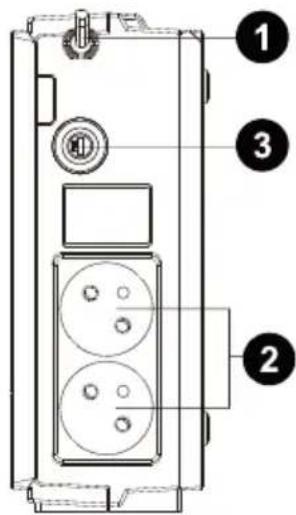
HR
①Glavna sklopka
② Indikator stanja UPS-a
③ Indikator pogreške / stanja baterije
(Pojedinosti pogledajte u tablici indikatora i alarma.)
Pogled straga:
natural_image
Two identical grayscale icons with black 'X' marks, no text or symbols presentnatural_image
Black electronic device with ventilation slots and a logo (no visible text or symbols on body)EN/DE/FR/ES/IT/GR/RU/UA/FI/HR/PL/PT/RO/SE
WAŻNE INSTRUKCJE DOTYCZĄCE BEZPIECZEŃSTWA
PL
- Compact size with stand and mounting flexibility
• Excellent microprocessor control guarantees high reliability
• Auto restart while AC is recovering - Simulated sine wave
- Cold start function
• Full protection: Discharge, overcharge, short circuit, and thermal Protection
natural_image
Front view of a rectangular electronic device with a small icon on the side panel (no readable text or symbols)Zasilacz UPS

Instrukcję obsługi


natural_image
Two 3D-rendered objects with black X marks, no text or symbols presentnatural_image
Black electronic device with ventilation slots and a logo (no visible text or symbols on body)EN/DE/FR/ES/IT/GR/RU/UA/FI/HR/PL/PT/RO/SE
IMPORTANTES INSTRUÇÃO ES DE SEGURANÇA
PT
- Compact size with stand and mounting flexibility
• Excellent microprocessor control guarantees high reliability
• Auto restart while AC is recovering - Simulated sine wave
- Cold start function
• Full protection: Discharge, overcharge, short circuit, and thermal Protection

II: Ligar à Rede Eléctrica e Carregar
III: Ligar as Cargas
natural_image
Black electronic device with ventilation slots and a logo (no visible text or symbols on body)EN/DE/FR/ES/IT/GR/RU/UA/FI/HR/PL/PT/RO/SE
RO
IMPORTANT SAFETY INSTRUCTIONS
RO
SAVE THESE INSTRUCTIONS – This manual contains important instructions for models PowerWalker VFD 400/600/800 that should be followed during installation and maintenance of the UPS and batteries.
- This product is specially designed for PCs and it is not recommended for use in any life-supporting system and other specific important equipment.
• This equipment can be operated by any individual with no previous training. - Do not plug household appliances such as hair dryers to UPS receptacles.
- This unit intended for installation in a controlled environment (temperature controlled, indoor area free of conductive contaminants). Avoid installing the UPS in locations where there is standing or running water, or excessive humidity.
- Risk of electric shock, do not remove cover. No user serviceable parts inside. Refer servicing to qualified service personnel.
- The utility power outlet shall be near the equipment and easily accessible. To isolate UPS from AC input, remove the plug from the utility power outlet.
- If UPS is to be stored for a long time, it is recommended to recharge the batteries (by connecting the utility power to UPS, switch "ON"), once a month for 24 hours to avoid a full battery discharge.
- Please do not use the UPS in excess of the rated load capacity.
- The UPS contains one/two large-capacity batteries. So the shell shall not be opened, otherwise such dangers as electric shock will be caused. If any internal overhaul or replacement of the battery is required, please contact the distributor.
- The internal short circuiting of the UPS will lead to dangers such as electric shock or fire, therefore, no water containers (such as a water glass) shall be placed on the top of the UPS so as to avoid such dangers as electric shock.
- Do not dispose of battery or batteries in a fire. The battery may explode.
- Do not open or mutilate the battery or batteries. Released electrolyte is harmful to the skin and eyes. It may be toxic.
- Icon on the rating label stands for phase symbol.
- A battery can present a risk of electrical shock and high short circuit current. The following precautions should be observed when working on batteries :
- Remove watches, rings, or other metal objects from the hand.
-
Use tools with insulated handles.
-
Servicing of batteries should be performed or supervised by personnel knowledgeable of batteries and the required precautions. Keep unauthorized personnel away from batteries.
- When replacing batteries, replace with the same type and number of the sealed lead-acid batteries.
• The maximum ambient temperature rating is 40^ C. - This pluggable type A equipment with battery already installed by the supplier is operator installable and may be operated by lavmen.
- During the installation of this equipment it should be assured that the sum of the leakage currents of the UPS and the connected loads does not exceed 3.5mA.
- Attention, hazardous through electric shock. Also with disconnection of this unit from the mains, hazardous voltage still may be accessible through supply from battery. The battery supply should be therefore disconnected in the plus and minus pole of the battery when maintenance or service work inside the UPS is necessary.
- The mains socket outlet that supplies the UPS shall be installed near the UPS and shall be easily accessible.
- In case smoke is found coming out from the device, please cut off the power supply quickly and contact the distributor.
• Do not keep or use this product in any of the following environments:
○ Any area with combustible gas, corrosive substance or heavy dust.
○ Any area with extraordinarily high or low temperature (above 40^ C or below 0^ C) and humidity of more than 90%.
○ Any area exposed to direct sunshine or near any heating apparatus.
○ Any area with serious vibrations.
o Outdoor.
- In the event that there is fire occurring in the vicinity, please use dry-power extinguishers. The use of liquid extinguishers may give rise to the danger of electric shock.
This product complies with the safety and environmental regulations in EU.
If the time arises to throw away your product, please recycle all the components possible. Batteries and rechargeable batteries are not to be disposed in your domestic waste! Please recycle them at your local recycling point. Together we can help to protect the environment.
CE

RO
1. Introducere
RO
- Compact size with stand and mounting flexibility
• Excellent microprocessor control guarantees high reliability
• Auto restart while AC is recovering - Simulated sine wave
- Cold start function
• Full protection: Discharge, overcharge, short circuit, and thermal Protection

natural_image
Black electronic device with ventilation slots and a logo (no visible text or symbols on body)Snabbstartguide
EN/DE/FR/ES/IT/GR/RU/UA/FI/HR/PL/PT/RO/SE
IMPORTANT SAFETY INSTRUCTIONS
SE
- Compact size with stand and mounting flexibility
• Excellent microprocessor control guarantees high reliability
• Auto restart while AC is recovering - Simulated sine wave
- Cold start function
• Full protection: Discharge, overcharge, short circuit, and thermal Protection
2. Paketinnehåll
You should have received the following items inside of package:
UPS-enhet

Användarmanual
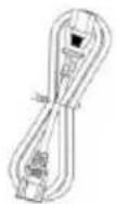
Nätkabel
3. Produktöversikt
Framsidan:
SE