VFD 600 APFC - Uninterruptible power supply PowerWalker - Free user manual and instructions
Find the device manual for free VFD 600 APFC PowerWalker in PDF.

| Brand | PowerWalker |
| Model | VFD 600 APFC |
| Product Type | Uninterruptible Power Supply (UPS) |
| Topology | Standby (Offline) |
| Rated Power | 600 VA / 300 W |
| Nominal Input Voltage | 220 VAC |
| Input Voltage Range | 170–270 VAC |
| Input Frequency | 50/60 Hz |
| Output Voltage (Battery Mode) | 220 VAC ±10% |
| Waveform (Battery Mode) | Step Wave |
| Transfer Time | 2–8 ms typical, 12 ms max |
| Battery Type | Sealed Lead-Acid, 12V / 5Ah x1 |
| Typical Runtime (100 W) | 17 min |
| Recharge Time (90%) | 10 hours max |
| Outlets | 6 outlets (4 battery backup + 2 surge-only), Schuko/French type |
| Protections | TVSS, overload, short circuit, modem/phone surge |
| LED Indicators | Green LED (normal mode), red LED (fault) |
| Audible Alarm | Beep according to status (battery, fault, overload) |
| Dimensions (W x D x H) | 320 x 125 x 86 mm |
| Net Weight | 3.1 kg |
| Operating Temperature | 0–40 °C |
| Operating Humidity | 20–90% non-condensing |
| Installation | Indoor, clean and ventilated environment |
| Maintenance | Charge battery for 8-10h before first use; replace battery by qualified technician |
| Repairability | Contains no user-serviceable parts; service by qualified technician |
| Safety | Disconnect all sources before service; do not open; beware of electric shock |
| DC Start Function | Yes (start on battery without mains) |
Frequently Asked Questions - VFD 600 APFC PowerWalker
User questions about VFD 600 APFC PowerWalker
0 question about this device. Answer the ones you know or ask your own.
Ask a new question about this device
Download the instructions for your Uninterruptible power supply in PDF format for free! Find your manual VFD 600 APFC - PowerWalker and take your electronic device back in hand. On this page are published all the documents necessary for the use of your device. VFD 600 APFC by PowerWalker.
USER MANUAL VFD 600 APFC PowerWalker
Standby (Offline) UPS
EN
PowerWalker VFD 600 APFC
PowerWalker VFD 800 APFC
PowerWalker VFD 600 APFC/FR
PowerWalker VFD 800 APFC/FR

natural_image
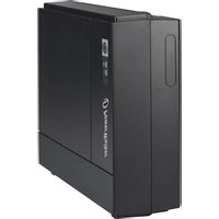
Two black power walkers with multiple charging ports and indicator lights, no visible text or symbols on the devices themselves.Manual
EN/DE/FR/PL/RU/PT
Uninterruptible Power Supply System
IMPORTANT SAFETY INSTRUCTIONS SAVE THESE INSTRUCTIONS
CAUTION!!
Please read the following information carefully and save this manual for further reference. Disregard of these safety notes may endanger life or health, as well as the function of the equipment and the safety of your data.
- Risk of Electric Shock Heatsinks are live. Disconnect unit before servicing.
- Risk of Electric Shock. This unit receives power from more than one source. Disconnection of AC sources and the DC source is required to de-energize this unit before servicing.
- Risk of Electric Shock. Hazardous live parts inside this unit are energized from the battery supply even when the input AC power is disconnected.
● Risk of Electric Shock. Do not remove cover. No user serviceable parts inside. Refer servicing to qualified service personnel.
- To reduce the risk of fire, replace only with same type of fuse. Refer servicing to qualified service personnel only.
- The sum of the leakage current of the UPS and the connected equipment should not exceed 3.5mA.
- Do not dispose of batteries in a fire as they may explode.
- Do not open or mutilate the battery or batteries. Released electrolytes are harmful to the skin and eyes. It may be toxic.
- A battery can present a risk of electric shock and of having a high short circuit current. The following precaution should be observed when working on batteries:
1) Remove watches, rings or other metal objects from the handles.
2) Use tools with insulated handles.
3) Wear rubber gloves and boots.
4) Do not lay tools or metal parts on top of batteries.
5) Disconnect charging source prior to connecting or disconnecting
batteries terminal.
- To replace the batteries by qualified service personnel. Use the same number and type of sealed lead-acid batteries.
● This pluggable type A equipment with battery already installed by the supplier is operator installable and may be operated by laymen. - The mains socket outlet that supplies the UPS shall be installed near the UPS and shall be easily accessible.
● Sealed, lead-acid, 6 cells battery.
● Φ on the rating label stands for phase symbol.
● The maximum ambient temperature rating is 40°C.
WARNING!!
● Refer servicing to qualified service personnel only.
● To reduce the risk of fire or electric shock, install in a temperature and humidity controlled indoor area free of conductive contaminants.
- Risk of Electric Shock. Battery circuit is not isolated from AC input, hazardous voltage may exist between battery terminals and ground. Test before touching.
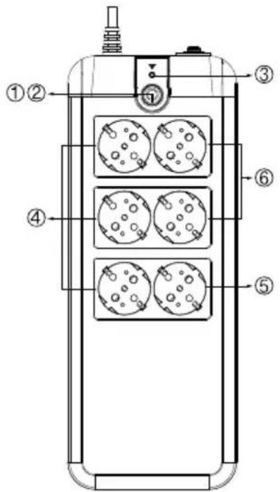
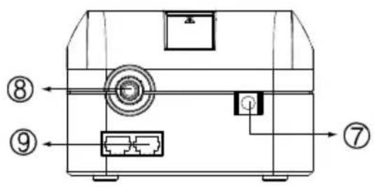
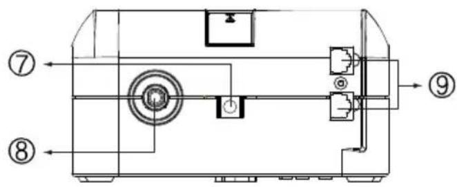
System Description
Top --
- Power On/Off Switch
- Green LED : AC Mode/Battery mode
- Red LED: Fault LED
- All receptacles are surge protected
- Surge protection receptacles
- Battery power supplied receptacles
Side --
- AC Input
- Breaker
- Modem/Phone Line Surge Protection
VFD 600 APFC
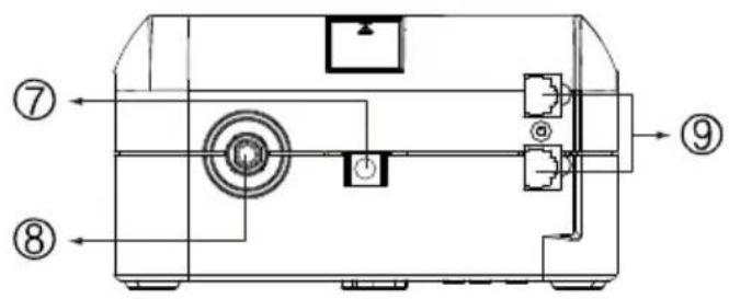
VFD 800 APFC
Installation & Operation
Installing the PowerWalker VFD 600/800 APFC UPS is as easy as the
following steps shown. Be aware that the Power Switch must be kept in the "ON" position and all equipment must be plugged into the Battery Power Supplied Receptacles, otherwise, the UPS will be disabled and your equipment will not be protected during a power failure.
EN
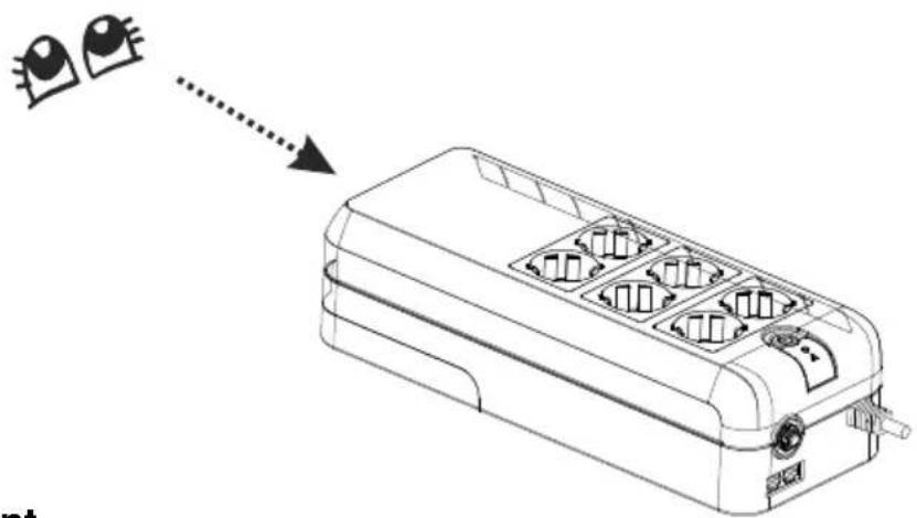
1. Inspection
Remove the UPS from its packaging and inspect it for damage that may have occurred during shipping. If any damage is discovered, repack the unit and return it to the place of purchase.
natural_image
Line drawing of a multi-wheeled electrical enclosure with internal compartments and a dotted arrow indicating direction (no text or symbols)2. Placement
Install the UPS unit in any protected environment that provides adequate airflow around the unit, and is free from excessive dust, corrosive fumes and conductive contaminants. DO NOT operate your UPS in an environment where the ambient temperature or humidity is high.

natural_image
Three symbolic illustration signs: sun with sunglasses, smoke with a chimney, and cloud with raindrops (no text or labels)3. Charging
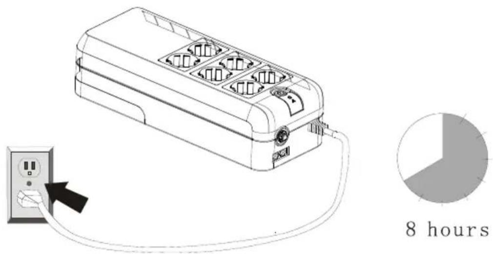
This unit is shipped from the factory with its internal battery fully charged.
However, some energy may be lost during shipping, so the battery should be recharged before using it. Plug the unit into an appropriate power supply, then switch on UPS and allow the UPS to charge fully by leaving it plugged in for at least 8-10 hours with no load (no electrical devices such as computers, monitors, etc.) connected.
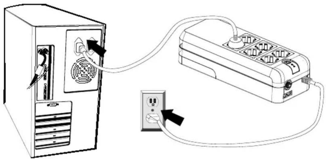
4. Computer Connection
Connect one computer-related device into one of the battery supplied receptacles on the top of UPS. PowerWalker VFD 600/800 APFC UPS provides six receptacles, all with surge protection, four of them including battery backup.
natural_image
Line drawing of a computer tower connected to an electrical outlet via cable (no text or symbols)EN
5. Peripheral Equipment Connection
Plug your peripheral equipment (printer, scanners, speakers) into the full-time surge protection outlets. These receptacles do not provide any power during a power failure.
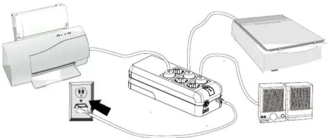
natural_image
Diagram of a power distribution system showing connections between printer, socket, and server units (no text or labels)Note: DO NOT plug a laser printer, copier, space heater, vacuum or other large electrical device into the UPS. The power demands of these devices will overload and possibly damage the unit.
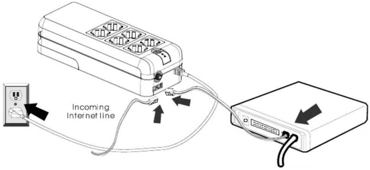
6. Modem/Phoneline Connection
Plug incoming internet line into the “In” socket at the side panel of the UPS. Use one more internet line cable and plug one end of the internet line cable to the “Out” socket at the side panel of the UPS. Plug the other end of the
modem input socket as shown.
7. Circuit Breaker
When short circuit happens, the circuit breaker will pop-up and then the UPS will shutdown automatically. After waiting for 2 minutes, please press the circuit breaker button again and the mains (AC power) will comeback.
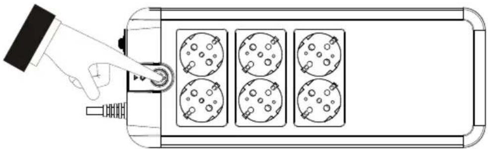
8. Turn On/Off
Press power switch 2 seconds to turn on the UPS.
Press power switch again to turn off the UPS.
natural_image
Top-down schematic of a device with four circular components and a hand pointing to a button (no text or symbols)9. DC Start Function
DC Start Function enables UPS to be started up when AC utility power is not available and battery is fully charged. Just simply press the power switch to turn on the UPS.
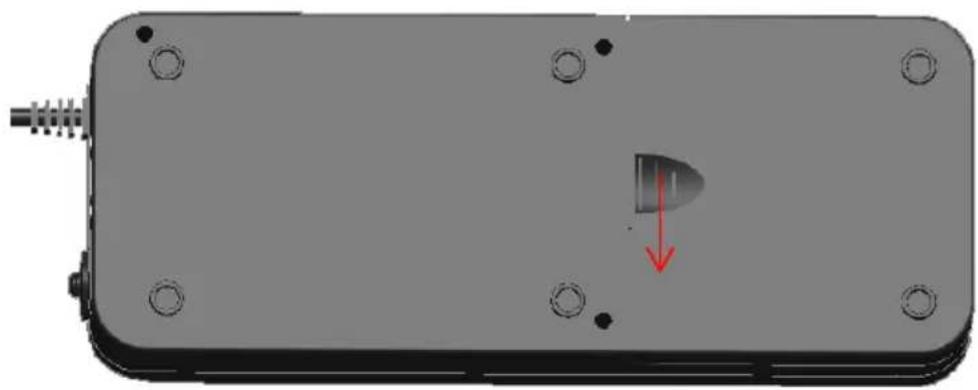
10. Battery Replacement
CAUTION:
Battery replacement should be performed by qualified service personnel. Please follow the charts below to replace the batteries.
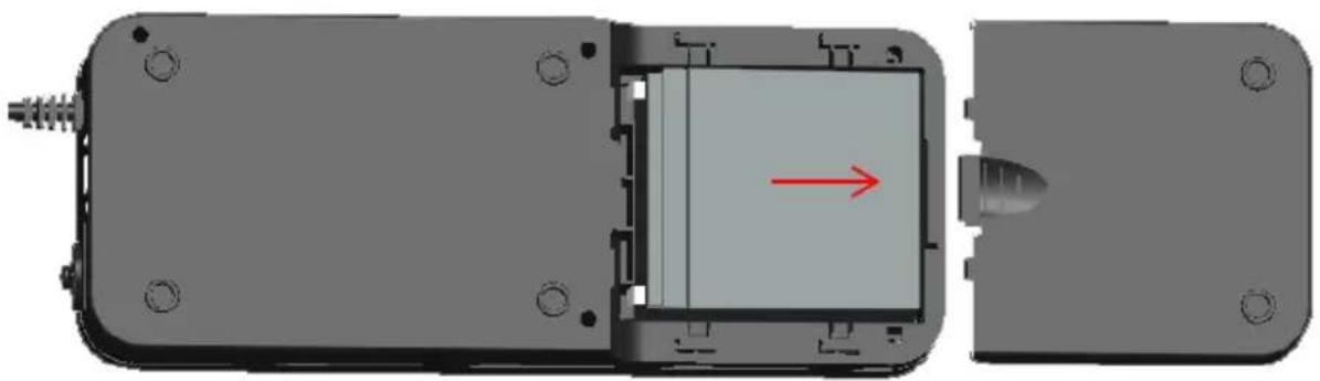
Step 1: Please prize up the battery cover gently.
natural_image
3D rendering of a mechanical component with mounting holes and a highlighted internal part (no text or symbols)Chart 1
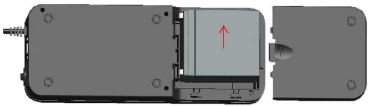
Step 2: Please remove the battery cover gently.
natural_image
Mechanical assembly diagram showing internal components with a red arrow indicating direction (no text or symbols present)Chart 2
EN
Step3: After removing battery cover, gently extract the battery by disconnecting the two wires connecting to the UPS. Be sure to replace the same type of batteries and dispose of old batteries properly at an appropriate recycling facility.
natural_image
Mechanical assembly diagram showing internal components with a red arrow indicating direction (no text or symbols present)Chart 3
Specification
| POWER RATING | 600VA/300W | 800VA/420W | ||
| INPUT | Pure Sine Wave | |||
| Range of Input Voltage | 170Vac~270Vac | |||
| Nominal Voltage | 220Vac | |||
| Nominal Frequency | 50H/60HZ | |||
| OUTPUT | ||||
| Line Mode | Same as input | |||
| Battery Mode | Step wave | |||
| Line Mode Voltage | Same as input voltage | |||
| Battery Mode Voltage | 220Vac±10% | |||
| Line Mode Frequency | Same as input frequency | |||
| Battery Mode Frequency | 50Hz/60Hz ±1Hz | |||
| Transfer time | 2-8ms typical ,12ms Max | |||
| BATTERY | ||||
| Battery type | 600VA | 800VA | ||
| 12V/5Ah*1 | 12V/7Ah*1 | |||
| Backup time 100W SPS LOAD | ||||
| 17mins | 20mins | |||
| Recharge time | 10 hours max. (Recharge to 90% Capacity) | |||
| DISPLAY | ||||
| Condition | Green Led/ Red Led | |||
| Line mode normal | Lighting/ Off | |||
| Battery normal | Lighting per 5s/ Off | |||
| Battery low | Lighting per 1s/ Lighting | |||
| Fault | Off/ Lighting | |||
| Over load(battery mode) | Lighting per 1s/ Lighting | |||
| AUDIBLE ALARM | ||||
| Condition | Buzzer | |||
| Battery normal | Buzzing Per 5s | |||
| Battery low | Buzzing Per 1s | |||
| Fault | Continuous sounding | |||
| Over load | Buzzing Per 0.5s | |||
| PROTECTION | TVSS / Over load / Short Circuit Protection/Over charge | |||
| PHYSICAL | 600VA | 800VA | ||
| Dimension (DxWxH) | 320*125*86(mm) | 335*170*92.5(mm) | ||
| Net Weight | 3.1KG | 4.1KG | ||
| Outlets | Schuko type/French type | |||
| 6 outlets (2 for surge only, 4 for battery backup) | ||||
| ENVIRONMENT | Operation Temperature/ Operation Humidity | |||
| 0-40°C/0%-85% | ||||
Trouble Shooting
If the UPS failed to operate properly, please review the following points firstly.
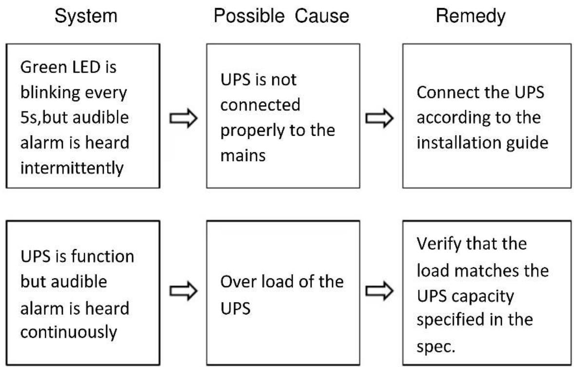
flowchart
graph LR
    A["Green LED is blinking every 5s, but audible alarm is heard intermittently"] --> B["Possible Cause"]
    B --> C["UPS is not connected properly to the mains"]
    C --> D["Connect the UPS according to the installation guide"]
    E["UPS is function but audible alarm is heard continuously"] --> F["Over load of the UPS"]
    F --> G["Verify that the load matches the UPS capacity specified in the spec."]
Standby-USV (Offline)
PowerWalker VFD 600 APFC
PowerWalker VFD 800 APFC
PowerWalker VFD 600 APFC/FR
PowerWalker VFD 800 APFC/FR

natural_image
Two black power walkers with three socket outlets, one labeled 'Power Walker' and the other 'Power Walker', shown against a white background (no additional text or symbols visible)Bedienungsanleitung
DE
Seite --
VFD 600 APFC
VFD 800 APFC
natural_image
Line drawing of a multi-wheeled electrical appliance with internal compartments and a dotted arrow pointing to it (no text or symbols)2. Aufstellung
natural_image
Three symbolic illustrations: sun with sunglasses, smoke with smokestacks, and cloud with raindrops (no text or labels)3. Aufladen
natural_image
Line drawing of a desktop computer tower connected to an electrical outlet via cable (no text or symbols)natural_image
Diagram of a power distribution system showing connections between a printer, circuit board, and server (no text or labels)7. Sicherung
natural_image
Top-down schematic of a device with four circular components and a hand pointing to a button (no text or symbols)9. DC-Startfunktion
natural_image
3D rendering of a rectangular electronic component with mounting holes and a small internal component, marked with a red arrow indicating direction (no text or symbols)Abbildung 1
natural_image
Mechanical assembly diagram showing a component with a red arrow indicating direction, no text or symbols presentAbbildung 2
natural_image
Mechanical assembly diagram showing internal components with a red arrow indicating direction (no text or symbols present)Abbildung 3
Spezifikation
PowerWalker VFD 600 APFC
PowerWalker VFD 800 APFC
PowerWalker VFD 600 APFC/FR
PowerWalker VFD 800 APFC/FR

natural_image
Two black power walkers with multiple charging socket ports and indicator lights, shown side by side (no text or symbols visible on devices)Manuel
FR
Côté --
VFD 600 APFC
VFD 800 APFC
2. Positionnement
natural_image
Three symbolic illustration signs: sun with sunglasses, smoke with smokestacks, and cloud with raindrops (no text or labels)3. Charge
natural_image
Line drawing of a computer tower connected to an electrical outlet via cable (no text or symbols)natural_image
Diagram showing connections between a printer, power strip, and server unit (no text or symbols present)7. Disjoncteur
natural_image
Top-down schematic of a device with four circular components and a hand pointing to a button (no text or symbols)natural_image
3D rendering of a rectangular electronic device with mounting holes and a small internal component, marked with a red arrow (no text or symbols)Graphique 1
natural_image
Mechanical assembly diagram showing a component with a red arrow indicating direction, no visible text or symbolsGraphique 2
natural_image
3D mechanical assembly diagram showing internal components with a red arrow indicating direction (no text or symbols)Graphique 3
PowerWalker VFD 600 APFC
PowerWalker VFD 800 APFC
PowerWalker VFD 600 APFC/FR
PowerWalker VFD 800 APFC/FR

natural_image
Two black power walkers with multiple charging pins, one labeled 'Power Walker' and the other 'Power Walker', shown without any additional text or symbols.Manual
PL
Widok z boku --
VFD 600 APFC

VFD 800 APFC
natural_image
Three symbolic illustration signs: sun with sunglasses, smokestack with flame, and cloud with smoke (no text or labels)3. Ładowanie
natural_image
Line drawing of a desktop computer connected to an electrical outlet via cable (no text or symbols)natural_image
Diagram of a printer connected to an electrical outlet with a power supply unit, showing connections without any text or symbols.7. Wyłącznik
natural_image
Diagram of a hand pressing a button on a device panel with four circular components (no text or symbols)PL
natural_image
3D rendering of a mechanical component with mounting holes and a highlighted internal part (no text or symbols)Chart 1
Step 2:
natural_image
Mechanical assembly diagram showing internal components with a red arrow indicating direction (no text or symbols present)Chart 2
Step3:
natural_image
Mechanical assembly diagram showing internal components with a red arrow indicating direction (no text or symbols present)Chart 3
Specyfikacja
PowerWalker VFD 600 APFC
PowerWalker VFD 800 APFC
PowerWalker VFD 600 APFC/FR
PowerWalker VFD 800 APFC/FR

natural_image
Two black power walkers with multiple charging pins, one with a green indicator light and the other with a yellow indicator light (no visible text or symbols on devices)VFD 600 APFC
VFD 800 APFC
natural_image
Line drawing of a multi-chamber electric heater with internal compartments and a dotted arrow indicating direction (no text or symbols)2. Размещение
natural_image
Three symbolic illustrations: sun with sunglasses, smoke with smokestacks, and cloud with smoke and raindrops (no text or labels)3. Зарядка
natural_image
Diagram showing connection between a desktop computer tower and an electrical power strip (no text or symbols present)natural_image
Diagram of a household air conditioner system with printer, socket, and server connected via cable (no text or labels)7. Прерыватель цени
natural_image
Top-down schematic of a device with four circular components and a hand pointing to a button (no text or symbols)natural_image
3D rendering of a mechanical component with mounting holes and a highlighted internal part, showing no text or symbols.Рис 1
natural_image
Mechanical assembly diagram showing a component with a red arrow indicating direction, no text or symbols presentРис 2
natural_image
3D mechanical assembly diagram showing internal components with a red arrow indicating direction (no text or symbols)Рис 3
Спецификации
PowerWalker VFD 600 APFC
PowerWalker VFD 800 APFC
PowerWalker VFD 600 APFC/FR
PowerWalker VFD 800 APFC/FR

natural_image
Two black power walkers with multiple charging ports and indicator lights, shown side by side (no text or symbols visible on devices)Manual
PT
Parte Lateral:
VFD 600 APFC
VFD 800 APFC
natural_image
Line drawing of a multi-wheeled electrical connector with internal compartments and ports (no text or symbols)2. Instalação
natural_image
Three symbolic illustration signs: sun with sunglasses, smokestack with flame, and cloud with smoke (no text or labels)3. Carregamento
natural_image
Line drawing of a computer tower connected to an electrical outlet via cable (no text or symbols)PT -
natural_image
Diagram of a power distribution system showing connections between printer, socket, and server units (no text or labels)natural_image
Top-down schematic of a device with four circular components and a hand pointing to a button (no text or symbols)natural_image
3D rendering of a mechanical component with mounting holes and a red arrow indicating a downward motion (no text or symbols)Imagem 1
natural_image
Mechanical assembly diagram showing internal components with a red arrow indicating direction (no text or symbols present)Imagem 2
natural_image
Mechanical assembly diagram showing internal components with a red arrow indicating direction (no text or symbols present)Imagem 3
Especificações