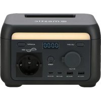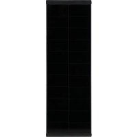
MPS-1000 - Battery charger Mestic - Free user manual and instructions
Find the device manual for free MPS-1000 Mestic in PDF.


User questions about MPS-1000 Mestic
0 question about this device. Answer the ones you know or ask your own.
Ask a new question about this device
Download the instructions for your Battery charger in PDF format for free! Find your manual MPS-1000 - Mestic and take your electronic device back in hand. On this page are published all the documents necessary for the use of your device. MPS-1000 by Mestic.
USER MANUAL MPS-1000 Mestic
text_image
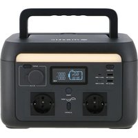
mestic LED LIGHT USB-A1 12W USB-C1 100W USB-A2 12W USB-C2 100W 60% 99-59 OUTPUT DC 12.4V POWER AC OUTPUTGebruiksaanwijzing NL User instructions EN Bedienungsanleitung DE Mode d'emploi FR
Instrucciones de uso ES Istruzioni per l'uso IT Betjeningsvejledning DK
Bruksanvisning SE Bruksanvisning NO
POWER STATION MPS-1000
NEDERLANDS
natural_image
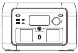
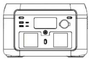
Front view line drawing of a portable device with control panel and buttons (no text or symbols)1
natural_image
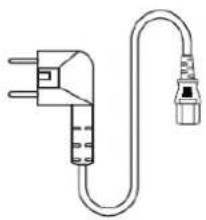
Line drawing of a U-shaped electrical plug with terminal connectors (no text or symbols)2
3
4
In de doos
- Powerstation
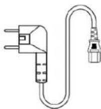
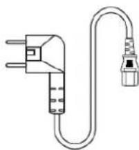
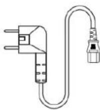
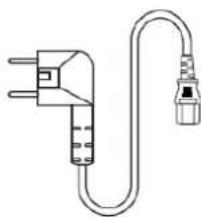
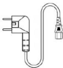
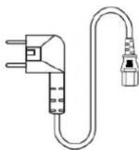
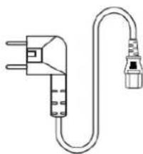
- Wisselstroomkabel
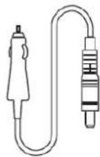
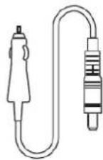
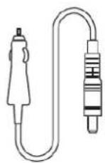
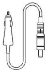
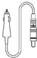
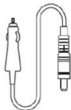
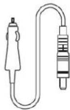
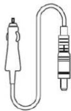
- Kabel autolader
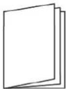
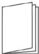
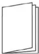
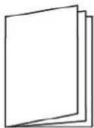
- Gebruikershandleiding
Parameters
| Algemeen | |
| Nettogewicht | 8.5kg |
| Afmeting | 301x227x193mm |
| Batterijcapaciteit | 614.4Wh, 51.2V===, 4Ah |
| Wi-Fi | Supported |
| Output | |
| AC-contactdoos (omvormermodus) | pure sine-wave, total 1000W (peak 1600W), 220-240V~, 50Hz/60Hz, 5A |
| AC-contactdoos (omloopmodus) | 220-240V~, 50Hz/60Hz, 200W Max., 5A |
| USB-A1+A2 | 5V=== 2.4A, 12W Max. |
| USB-C1/C2 | 5/9/9/15V=== 3A, 20V=== 5A, 100W Max. |
| Auto-oplader | 12.6V===10A, 126W Max. |
| Input | |
| AC-invoervermogen | 1500W max., 7.5A |
| AC-invoerspanning | 220-240V~, 50Hz/60Hz |
| PV-lading | 13-45V=== 12A, 400W Max. |
| Auto-oplaadingang | 12V/24V-accu ondersteund, 5A standaard |
| Adapter-invoer | 21V=== 5A, 105W Max. |
natural_image
Technical line drawing of a cylindrical device with internal grid pattern and mounting feet (no text or symbols)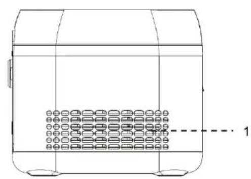
natural_image
Technical line drawing of a container with internal compartments and a dashed-line indicator labeled '1' (no text or symbols on the diagram itself)text_image
100% 8888.0 8888.0text_image
Diagram showing connection between a power outlet, switch, and solar panel array with labeled componentstext_image
Diagram showing connection between a USB port, a device with two ports, and an attached device with labeled ports and wiring.text_image
QR code image containing encoded data, no visible human-readable textEPS-functie
natural_image
Line drawing of a portable electronic device front panel with control buttons and display (no text or symbols)1
natural_image
Line drawing of a U-shaped electrical plug with terminal connectors (no text or symbols)2
3
4
In the box
- Power station
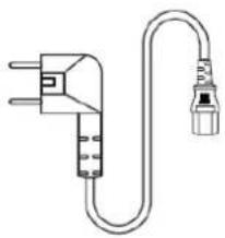
- AC cable
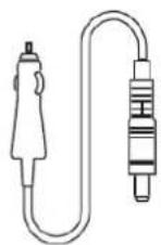
- Car charge cable
- User manual
Parameters
| General | |
| Net weight | 8.5kg |
| Dimensions | 301x227x193mm |
| Battery capacity | 614.4Wh, 51.2V===, 4Ah |
| Wi-Fi | Supported |
| Output | |
| AC outlet (inverter mode) | pure sine-wave, total 1000W (peak 1600W), 220-240V~, 50Hz/60Hz, 5A |
| AC outlet (bypass mode) | 220-240V~, 50Hz/60Hz, 200W Max., 1.1A |
| USB-A1+A2 | 5V=== 2.4A, 12W Max. |
| USB-C1/C2 | 5/9/9/15V=== 3A, 20V=== 5A, 100W Max. |
| Car charger | 12.6V===10A, 126W Max. |
| Input | |
| AC input power | 1500W max., 7.5A |
| AC input voltage | 220-240V~, 50Hz/60Hz |
| PV charging | 13-45V=== 12A, 400W Max. |
| Car input | 12V/24V battery supported, 5A standard |
| Adapter input | 21V=== 5A, 105W Max. |
| Charging Input | |
| AC charging power | 700W Max. |
| PV/car charging power | 400W Max |
| AC+PV charging power | 700W Max. |
| Battery | |
| Cell type | Lithium iron phosphate (LiFePO4) |
| Lifecycle | 3000 cycli |
| Protection | Protection against overheating, low temperature, over-discharge, overcharge, overload, short circuit, and overcurrent |
| Operating temperature | |
| Optimal operating temperature | 20°C - 30°C |
| Discharge temperature range | -20°C - 45°C |
| Charge temperature range | 0°C - 45°C |
| Storage temperature range | -20°C - 45°C (20°C - 30°C Recommended) |
| Battery Expansion | |
| Power input/output | 40-57.6V=== 12A charge (Max.), 24A discharge (Max.) |
| Nominal energy | 614Wh, support 6 expansion battery packs at most, separate selling. |
Note: Whether the product can be charged or discharged is subject to the actual battery pack temperature.
Safety instructions
-
Before using the power station, please read this user manual to ensure understanding and proper use.
-
Do not place a working power station close to any heat source, such as fire or a heater.
-
Avoid allowing the power station to come into contact with any liquid.
-
Do not use the power station in a strong electrostatic or strong magnetic field environment.
-
Do not disassemble the power station in any way or pierce it with a sharp object.
-
Avoid short-circuiting the power station with wires or other metal objects.
-
It is forbidden to step on, sit, or climb on this product.
-
Do not use non-genuine parts or accessories. For part or accessory replacement, please visit the official sales channel for purchase information.
-
When using the power station, strictly follow the operating temperature defined in this user manual. If the temperature is too high, the battery may catch fire or even explode. If the temperature is too low, the power station's performance will be seriously impaired, and normal use may be impacted.
-
Do not stack heavy objects on the power station.
-
Do not forcibly stop the fan or expose the power station to an unventilated or dusty environment when it is working.
-
Please avoid collisions, dropping, and violent vibrations. If a severe impact occurs, shut down the power supply immediately. Secure the power station firmly during transportation to prevent vibration and impact.
-
If the power station falls into water accidentally, place it in a safe and wide area, and keep yourself away from it until it's dry. The dried product is not to be used again. Dispose of it properly according to the discard instructions in this manual. If the power station is on fire, please use fire extinguishing equipment in the recommended order: water or water mist, sand, fire blanket, dry powder, carbon dioxide fire extinguisher.
-
If there is dirt on the power station, use a dry cloth to wipe it.
-
Place the power station carefully to prevent damage. If the power station is tipped over and seriously damaged, turn off the power station immediately, place the battery in a spacious area, keep it away from flammable materials and people, and discard it in accordance with the requirements of local laws and regulations.
-
Keep the power station out of the reach of children and pets.
-
Keep the power station in a dry and ventilated place.
-
In a humid environment (seaside, water, etc.), it is recommended to equip the power station with a moisture-proof bag. If water is found inside the product, do not use/start it again. Take countermeasures to prevent electric shock before touching the power station. Put it in a safe and waterproof open area and contact customer service immediately.
-
It is not recommended to use the power station to supply power for safety-related emergency medical equipment, including but not limited to medical-grade breathing machines (hospital version CPAP: Continuous Positive Airway Pressure), artificial lungs (ECMO, Extracorporeal Membrane Oxygenation). It can be used to supply power for the home version CPAP at home and does not require continuous professional monitoring. Follow your doctor's advice and consult the manufacturer for any restrictions on
the use of the device. For general medical equipment, pay attention to the power condition to ensure that power does not run out.
- Conditions permitting, be sure to discharge the battery completely, and then put the power station in the specified battery recycling bin.
- The power station contains batteries, which are dangerous. It is strictly prohibited to discard them in ordinary dustbins. For details, follow local laws and regulations on battery recycling and disposal.
- If the battery cannot be discharged completely due to a product failure, do not discard the battery directly in the battery recycling bin. Contact a professional battery recycling company for further disposal.
- The battery will not start after over-discharge. Please dispose of it.
- Power supplies will inevitably generate electromagnetic fields when in use, which might affect implantable medical devices or the normal operation of personal medical devices, such as pacemaker devices, cochlear implants, hearing aids, defibrillators, etc. If any of these medical devices are used, please consult the manufacturer about the restrictions on the use to ensure that the power station is operated at a safe distance from implanted medical devices such as pacemakers, cochlear implants, hearing aids, defibrillators, etc.
- When the power station is connected to a refrigerator, it may automatically shut down because of the power fluctuation property of the refrigerator. When connecting the power supply to a refrigerator that stores medicine, vaccines, or other valuable items, it is recommended to set the AC output to "Never off" in the APP, so as to ensure continuous power. Users should pay attention to power consumption.
- During the push-pull movement of this product, it is forbidden to put other items on this product.
Warning
- Do not overcharge the internal battery. See instruction manual.
- Do not smoke, strike a match, or cause a spark in the vicinity of the power station.
- Only charge the internal battery in a well-ventilated area.
- CAUTION: Risk of electric shock. Connect only to properly grounded outlets.
- CAUTION: Risk of injury to persons. Do not use this product if the power cord or the battery cables are damaged in any way.
- CAUTION: Risk of electric shock. Do not remove cover. No user serviceable parts inside. Refer servicing to qualified service personnel.
- CAUTION: This device is not intended for use in a commercial repair facility.
Product overview
text_image
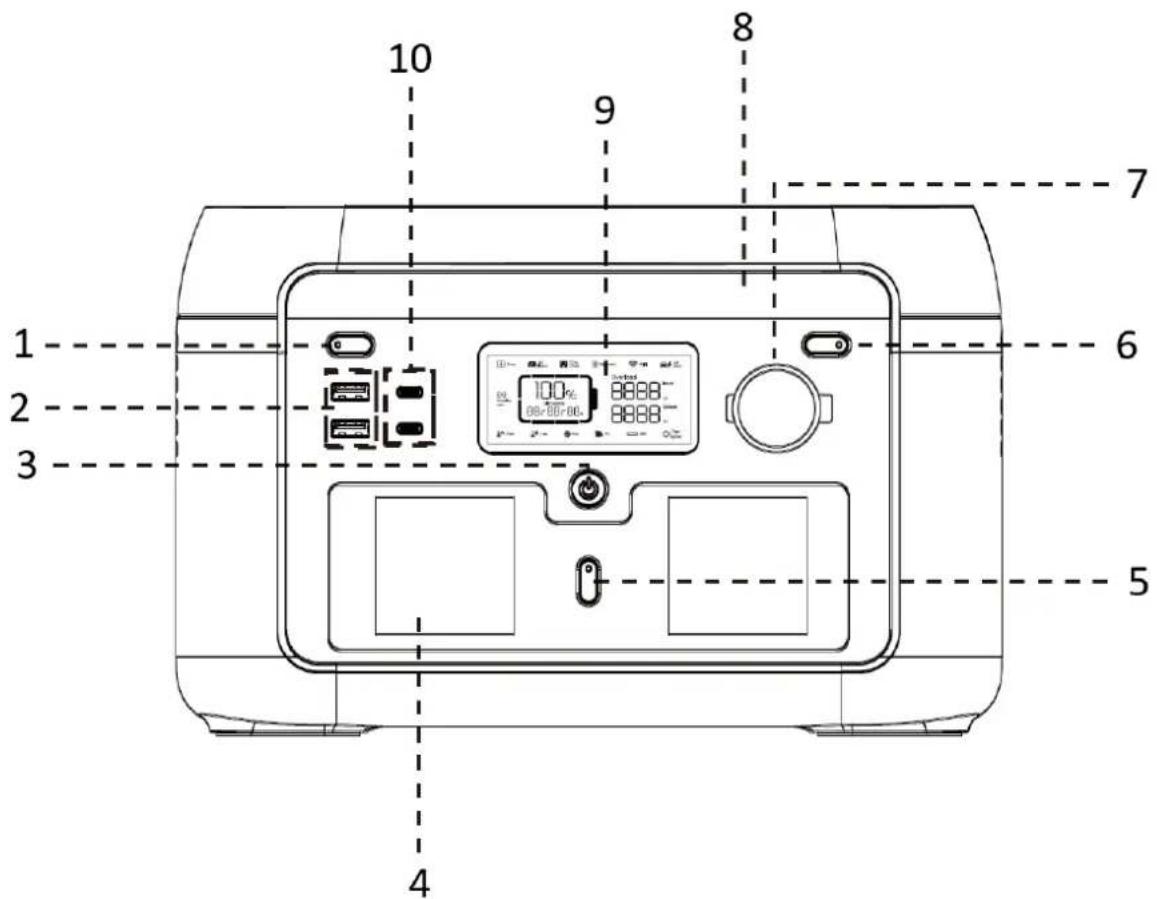
1 2 3 4 5 6 7 8 9 10- LED light button
- USB-A output port x2
- ON/OFF button
- AC output socket x2
- AC output button
- DC output ON/OFF
- Car charge output
- LED light
- LCD
- USB-C output port x2
natural_image
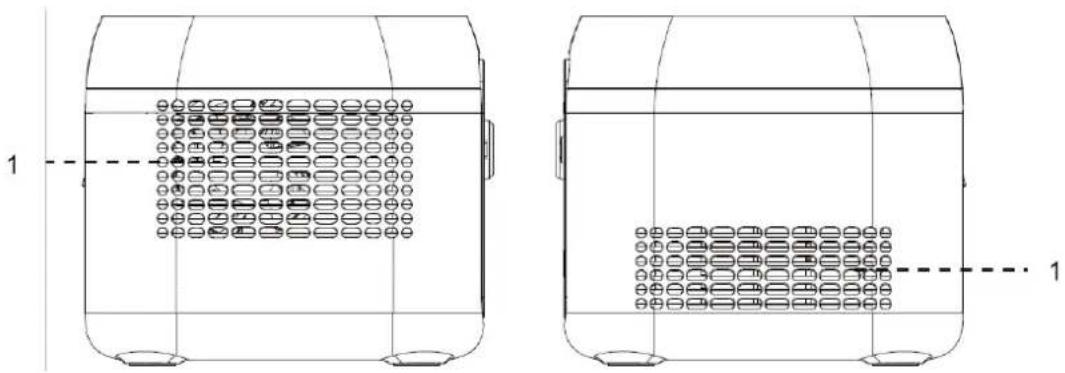
Technical line drawing of two identical cylindrical containers with internal compartments and mounting holes, no text or symbols present.- Ventilation opening
text_image
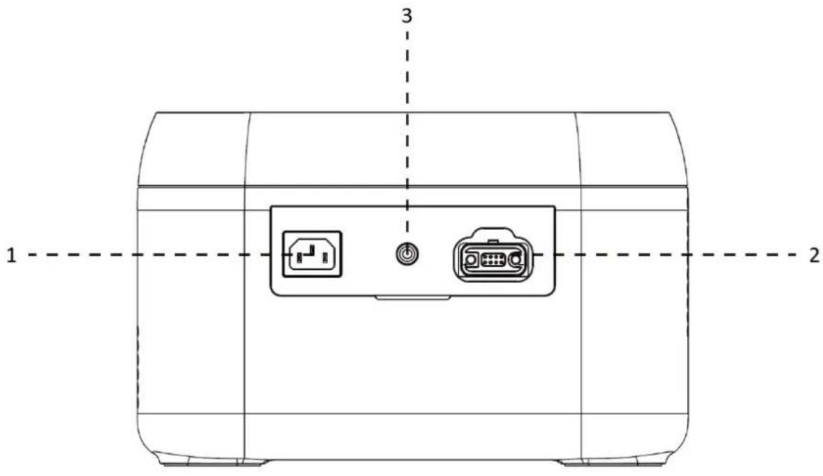
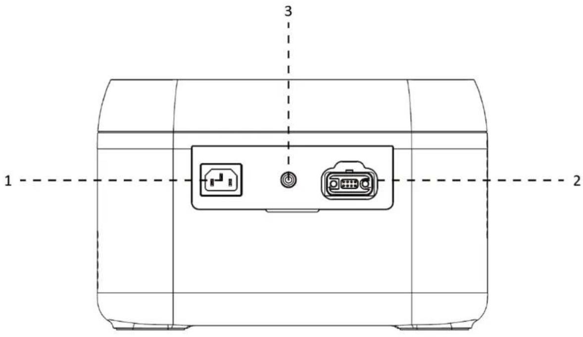
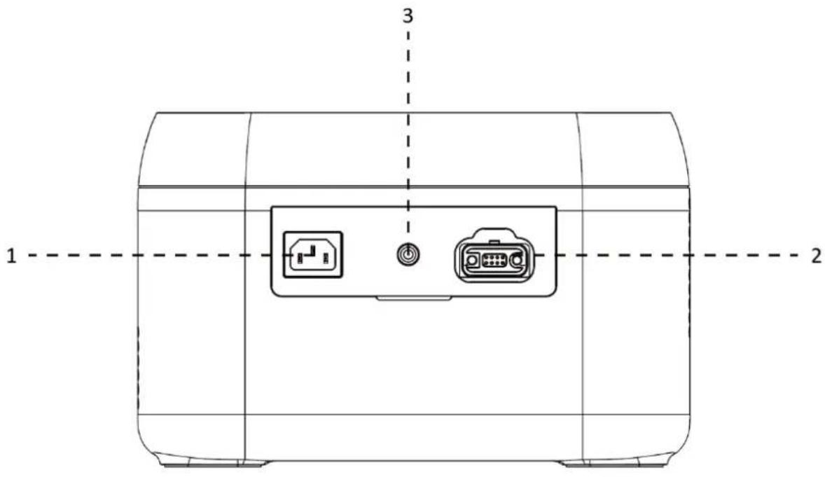
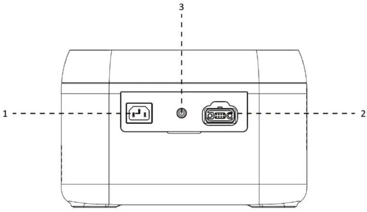
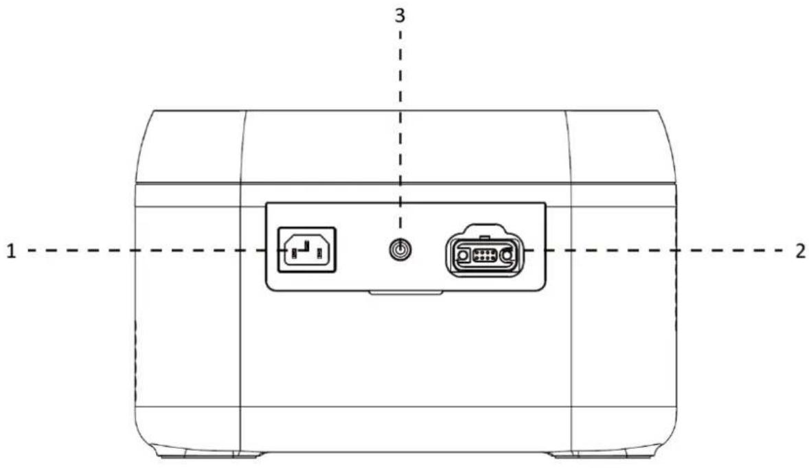
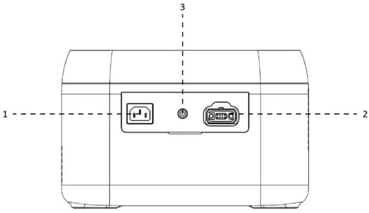
1 2 3- AC input socket
- Power in for battery expansion
- Solar / car charge input
text_image
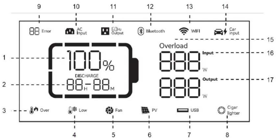
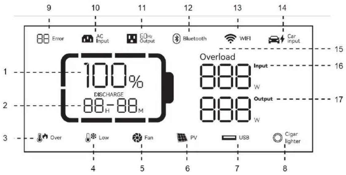
9 10 11 12 13 14 88 Error AC Input 60Hz Output Bluetooth WIFI Car input 15 1 100% Overload 16 DISCHARGE 88-H-88M Output 2 888 W W 3 Over Low Fan PV USB Cigar lighter 4 5 6 7 8- Remaining battery percentage
- Remaining charge/ discharge time
- Over temperature warning
- Low temperature warning
- Fan status
- PV charge
- USB output
- 12V socket
- Error code
- AC input
-
AC output
-
Bluetooth
- WiFi connection status
- Car charger
- Overload
- Input power
- Output power
Battery capacity: when the power station is being charged, the remaining battery percentage (1.) will flicker.
Wi-Fi connection status: The flickering icon indicates that the power station is ready for pairing. The icon will keep flickering if a mobile phone and power station are connected by hotspot. After a successful network connection, the icon will always be on. If the connection fails, the icon will be off.
Use
text_image
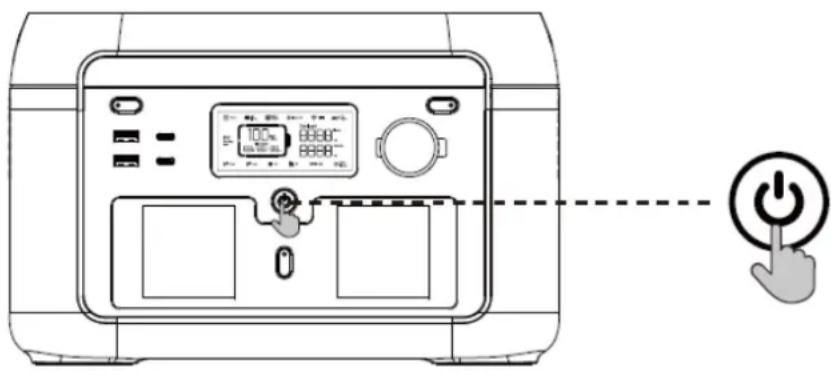
Diagram of a microwave oven with digital display and control buttons, connected to a power button icon- Press the main power switch to turn on the device; the screen and the power indicator will light up.
- If no operation is performed on the power station for 5 minutes, the power station will enter a hibernation state, and the LCD screen will automatically turn off. When there is a load change or operation on the power station, the LCD screen will automatically light up. Press the main power switch to turn on or turn off the LCD screen.
- Press and hold the main power switch to turn off the power station.
- In normal mode (when the power is above 5%), the default standby time of this product is 2 hours. When the AC output switch is not turned on, and there is no charge or discharge for 2 hours, the product will automatically shut down. The standby time can be set on the APP. When the power is 5% or below, the product will be forced to enter low power mode. In the case of no charge or discharge, the product will adjust the standby time according to the power and automatically shut down.
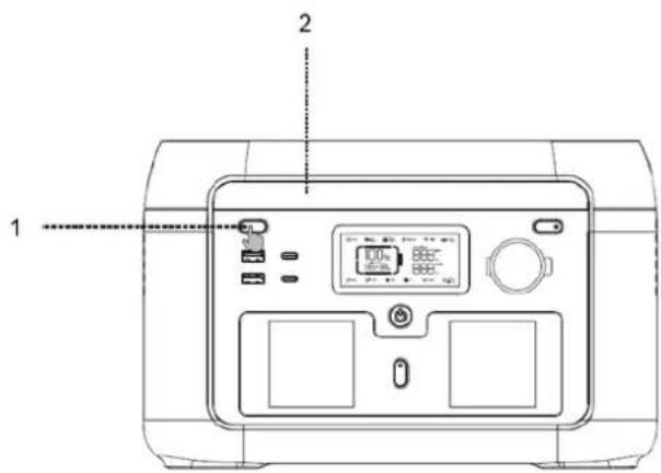
- In normal mode, long-press the LED light button to exit the automatic shutdown setting, and the battery icon on the screen will flash. Long-press again to enter the automatic shutdown setting, and the battery icon will not flash. (The automatic shutdown setting is to protect the battery from low power; exiting this setting may damage the battery life, so please use it with caution.)
text_image
1 2- Short-press LED light button
- Short-press the LED light button to switch between four modes: low light, medium light, bright light, SOS and light off.
text_image
USB output 12V DC output 1 2USB-output
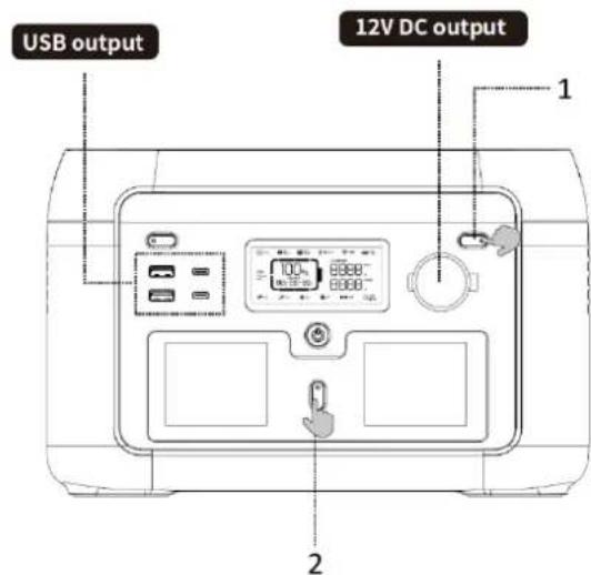
The USB output is enabled by default after the main switch is turned on.
12V DC-output
After the main switch is turned on, press the 12V DC output switch to turn on the DC output port.
Press the 12V DC output switch again to turn it off.
When the 12V DC output switch is turned on, the power station does not turn off automatically.
- Short-press 12V DC output power switch
-
Short-press AC output power switch
-
Note: When there is no AC input, long press the AC output button. You can switch the AC off-grid output frequency (50 Hz/60 Hz), long press 2 seconds to switch. The AC output icon will flash 3 times after successful switching.
-
After ensuring that the main power is turned on, short-press the AC output power switch to turn on the AC output. Short-press the AC output power switch again to turn it off.
- The default standby time of the AC output port is 1 hour. After 1 hour without any load on the AC output port of this product, the AC output power will be automatically turned off. In normal mode, long-press the LED light button; the AC output power switch can exit the automatic shutdown setting, and the battery icon on the screen will flash. Long-press again, and the AC output power switch enters the automatic shutdown setting, and the battery icon will not flash.
- Long-press the LED light button to exit the AC automatic shutdown setting: it is applicable to AC equipment below 10W and pulse working equipment.
- When the AC output is not in use, turn it off to save power consumption.
AC charging
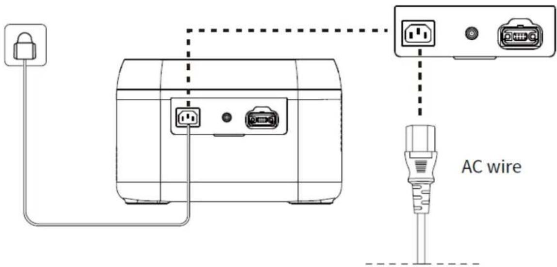
When the product is turned on, the standard fast-charging mode is activated. If your product has a Wi-Fi function, you can control the charging speed via the app.
text_image
AC wirePlease use the standard AC charging cable for fast charging. The AC charging cable should be plugged directly into a wall socket with 10A (or higher). We accept no responsibility for any damage caused by the use of an unofficial AC charging cable or failure to follow the instructions.
PV-charging
text_image
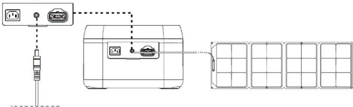
Diagram showing connection between a power connector, switch, and solar panel array with labeled components- Please follow the user manual to connect the solar panels.
- Before connecting the solar panel, check whether its output voltage is within the power station specifications to avoid damage to the power station.
- The interface of this product is DC7909. If you need an adapter cable from MC4 to DC7909, please purchase it yourself.
Battery expansion
Power station supports connection with 6 expansion battery packs at the same time for larger capacity. Please refer to the user manual of battery pack for details.
- Before connecting the battery pack, please make sure both power station and battery pack are off.
- After the battery pack is connected, check if battery icon is shown in the displays of both power station and battery pack.
- While in charging, please do not connect or remove the battery pack. If connection or need to connect or remove it, turn off power station prior to operation.
- Please do not touch the metal terminals. If there is foreign matter on the metal terminals, clean it with a dry cloth gently and carefully.
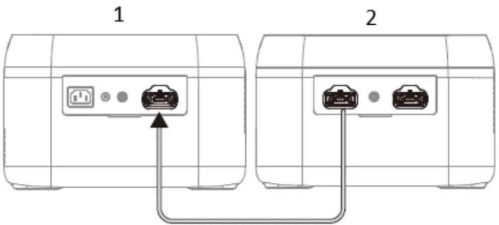
Parallel mode of 1 power station and 1 expansion battery pack
- Turn off the power station and expansion battery pack.
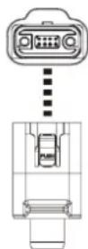
- The expansion cable plugs into the expansion port of the power station and the power input/output of the expansion battery pack.
- After parallelization, press power button of power station to enable the power station and battery pack to show current capacity. The power station shows the paralleled quantity, and capacity is expanded.
- After parallelization, connect ports of the power station for charging or discharging.
Both ports of the expansion battery pack can be connected to the expansion port of the power station. Both ports of the expansion cable can be connected to the ports of the expansion battery pack and the expansion port of the power station.
text_image
1 2- Powerstation
- Battery expansion pack
Both ports of the expansion battery pack can be connected to the expansion port of the power station. Both ports of the expansion cable can be connected to the ports of the expansion battery pack and the expansion port of the power station.
Car charging
text_image
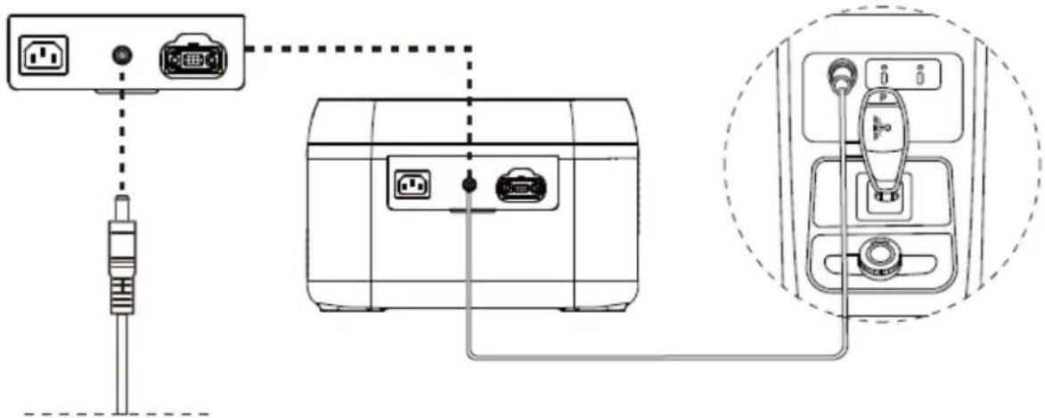
Diagram showing connection between a power connector, switch, and device with labeled ports and wiring connectionsThe power station can be charged using a car charging port. It should be charged after the car starts to avoid car battery loss and failure to start. At the same time, ensure a good connection between the car charging port and the cigarette lighter. We take no responsibility for any loss caused by improper operation.
Constant power
Please take note of the following while using constant power:
- The constant power output function is not enabled by default and can be turned on or off via the app.
-
The constant power output function is not enabled in the following cases:
-
When AC output is turned on during charging (bypass mode).
-
When constant power output is turned off.
-
The constant power output function is more suitable for heaters and motors instead of all electrical equipment. It is not suitable for some electrical appliances with voltage protection (such as precision instruments). The application of the constant power output function is subject to actual testing.
APP
You can control and view information and data about this product through the app. For detailed usage instructions, please refer to the WiFi Connection Instructions:

EPS Function
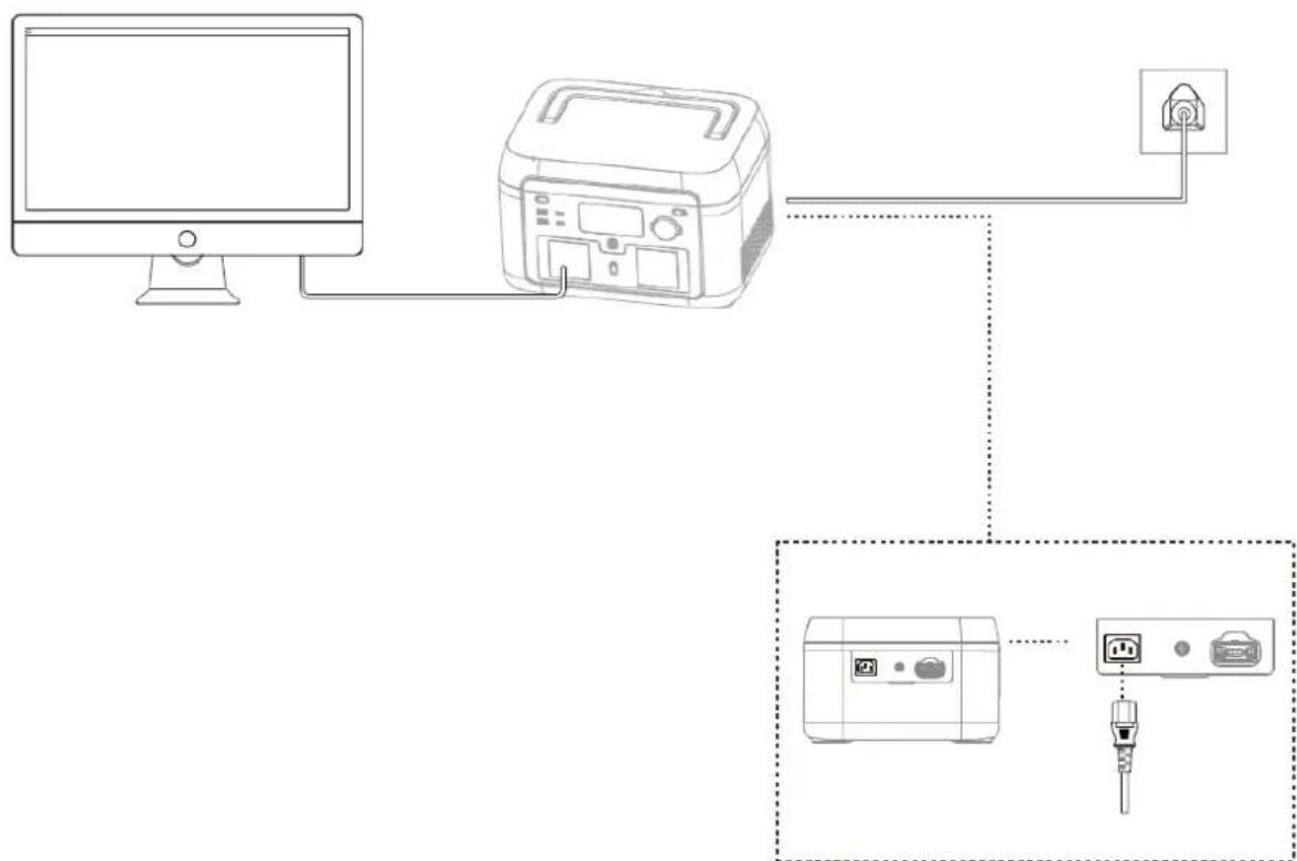
This product supports the EPS (emergency backup power) function. Connect the power grid to the AC input port of this product using the AC charging cable; it operates in Bypass mode (AC power comes from the grid, not the battery). In the event of a sudden power loss from the grid, the product can automatically switch to battery power supply mode within 14 milliseconds. At this time, it functions in inverter mode. Please note that this function does not support 0 milliseconds switching. Avoid connecting it to devices that require high uninterrupted power supply, such as data servers and workstations, unless compatibility is confirmed through multiple tests. It is recommended to use only one device at a time to avoid overload protection. If the device does not operate normally or data is lost due to failure to follow instructions, we will not be responsible.
flowchart
graph TD
    A["Computer"] --> B["Printer"]
    B --> C["Plug"]
    B --> D["Printer"]
    D --> E["Plug"]
Maintenance
- It is recommended to use or store the power station in an ambient temperature of 20\~30°C. Keep it away from water, heaters, and metal parts, and store it in a dry and ventilated place.
- For long-term storage, charge and discharge every 3 months, i.e., discharge to 0%, then charge to 100% and finally discharge to 48%-52%.
- For safety, do not store the power station with a temperature above 45°C or below -10°C.
- If the capacity is lower than 1%, please charge it to 60%. Long-term storage with a serious power shortage will cause irreversible damage to the cell and shorten the service life of the product.
- If the capacity is seriously insufficient and idle time is too long, the product will enter deep sleep mode, and it can only be used after being charged.
- After charging or discharging this product, wait for more than 30 minutes before using it.
Error codes
| Error no. | Fault Description | Solution** |
| 4 | Battery OTP fault (over-temperature protection) | Automatic shutdown. Temperature recovery enables restarting. |
| 5 | Battery UTP fault (under-temperature protection) | Automatic shutdown. Temperature recovery enables restarting. |
| 6 | OCP fault (overcurrent protection) | Automatic shutdown. Remove the overloading device. The fault will be cleared after a restart. |
| 7 | BMS board over-temperature fault | Automatic shutdown, delayed start. |
| 8 | Pre-charge fault | Automatic shutdown. The fault will be cleared after a restart. |
| 9 | Battery under-voltage fault | Automatic shutdown and charge. Contact customer service if the problem is not resolved after multiple charging attempts. |
| 11 | Abnormal INV battery voltage | Automatic recovery after the fault is cleared. |
| 12 | Grid voltage or frequency fault | The fault is cleared when the power grid returns to normal operation. |
| 13 | Abnormal INV BUS voltage | Automatic recovery after the fault is cleared. |
| 14 | Abnormal INV output | Automatic recovery after the fault is cleared. |
| 15 | INV discharge overload | Remove the overloading device. Automatic recovery after the fault is cleared. |
| 16 | Charge overload | Automatic recovery after the fault is cleared. |
| 17 | INV Tz | Automatic recovery after the fault is cleared. |
| 20 | MOSFET OTP fault | Automatic recovery after the product has cooled down. |
| 21 | Fan stopped | Turn the device on and off. Contact customer service if the issue persists. |
| 23 | Charge soft start fault | Turn the device on and off. Contact customer service if the issue persists. |
| 24 | MOSFET UTP fault | Turn the device on and off. Contact customer service if the issue persists. |
| 27 | DC input hardware overcurrent protection | Remove the DC load. Automatic recovery after reconnecting the DC input and turning the device on. |
| 28 | DC input software overcurrent protection | DC charging stops and will automatically resume once the fault is cleared. |
| 31 | PV output OVP fault (over-voltage protection) | Removing the PV charging interface will automatically restore functionality after a certain period of time. |
| 32 | DC input voltage overvoltage protection | Remove the DC charging interface for a certain period of time to recover automatically, or check whether the PV output fuse is disconnected. |
| 35 | DC input over-temperature protection | Stop DC charging. Automatic recovery after the fault is cleared. |
| 37 | Car charger output OTP fault | Turn off the output. Manual recovery after the fault is cleared. |
| 38 | Abnormal communication | Turn the device on and off or change the operating environment. Contact customer service if the issue persists. |
| 43 | Battery voltage is too low. The battery is damaged | Contact customer service for further assistance. |
Disclaimer
- The product has a built-in battery management system with protections such as overcharge, over-discharge, overcurrent, short circuit, high and low temperature, and abnormal communication. During the use of this product, protection may occur, causing output interruption. The power supply to special equipment, such as medical equipment or servers, and any indirect loss caused by accidental power failure, we do not take responsibility for. All accidents caused by illegal use, self-dismantling, and man-made damage we do not take responsibility for.
- Before using the power station, please read this user manual to ensure understanding and proper use. Keep the user manual for future reference. Improper operation may cause serious injury or result in product damage and property loss. By using the power station, you are deemed to have understood and accepted all terms and contents herein. Users promise to be responsible for their actions and all consequences arising therefrom. The company shall not be liable for any loss arising from the user not following this user manual.
- In compliance with laws and regulations, the manufacturer reserves the right of the final interpretation of this document and all related documents of this product. Subject to update, revision, or termination without prior notice, please visit the official website for the latest product information.
Recycling
This product bears the selective sorting symbol for waste electrical and electronic equipment. This means that this product must be handled pursuant to European Directive (2012/19/EU) in order to be recycled or dismantled to minimize its impact on the environment. For further information, please contact your local or regional authorities. Electronic products not included in the selective sorting process are potentially dangerous for the environment and human heath due to the presence of hazardous substances.
Declaration of conformity
Hereby Gimeg Nederland B.V., declares that the device Power Station MPS-300, complies with the basic requirements and other relevant regulations listed in the European Battery Directive (2023/1542/EU), Low Voltage Directive (2014/35/EU), Electromagnetic Compatibility (2014/30/EU), RoHS (2011/65/EU) and Radio Equipment (2014/53/EU). A complete declaration of conformity can be requested from the address listed on the back.
DEUTSCH
natural_image
Front view line drawing of a portable device with control panel and buttons (no text or symbols)1
natural_image
Line drawing of a U-shaped electrical plug with terminal connectors (no text or symbols)2
3

4
Im Karton
natural_image
Technical line drawing of two identical container-like structures with internal grid patterns, no text or symbols present.- Lüftungsöffnung
text_image
1 2 3text_image
100% 8888 8888text_image
Diagram showing connection between a power connector, switch, and solar panel array with labeled componentstext_image
Diagram showing connection between a power connector, switch, and device with labeled ports and wiring connectionstext_image
QR code image containing encoded data, no visible human-readable textEPS-Funktion
natural_image
Front view of a portable device with control panel and buttons (no text or symbols visible)1
natural_image
Line drawing of a U-shaped electrical plug with terminal connectors (no text or symbols)2
3

4
Dans la boîte
natural_image
Technical line drawing of a cylindrical device with internal grid pattern and mounting feet (no text or symbols)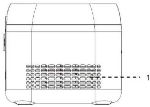
natural_image
Technical line drawing of a cylindrical device with internal grid pattern and mounting base (no text or symbols)text_image
Diagram of a device front panel with control buttons and a power button icon, showing battery status and display settings.text_image
Diagram showing connection between a power connector, battery pack, and solar panel array with labeled components.text_image
Diagram showing connection between a USB port, a device with two ports, and an attached device with a power outlet.text_image
QR code image containing encoded data, no visible human-readable textFonction EPS
natural_image
Line drawing of a portable electronic device front panel with control buttons and display (no text or symbols)1
natural_image
Line drawing of a U-shaped electrical plug with terminal connectors (no text or symbols)2
3
4
natural_image
Technical line drawing of a two-view container with internal grid pattern and side supports (no text or symbols)text_image
Diagram showing a device with control panel and power button, connected to a dashed line indicating connection.text_image
Diagram showing connection between a power connector, cable, and solar panel with labeled componentstext_image
Diagram showing connection between a power connector, switch, and device with labeled ports and wiring connectionstext_image
QR code image containing encoded data, no visible human-readable textFunción EPS
natural_image
Front view line drawing of a portable electronic device with control panel and buttons (no text or symbols)1
natural_image
Line drawing of a U-shaped electrical plug with terminal connectors (no text or symbols)2
3
4
Nella confezione
natural_image
Technical line drawing of two identical cylindrical containers with internal compartments and mounting holes, no text or symbols present.- Fori di areazione
text_image
1 2 3text_image
Diagram of a toaster front panel with digital display and control buttons, connected to a power button icontext_image
Diagram showing connection between a power connector, device, and solar panel array with labeled componentstext_image
Diagram showing connection between a USB port, a device with two ports, and an attached device with a power outlet.text_image
QR code image containing encoded data, no visible human-readable textFunzione EPS
natural_image
Front view line drawing of a portable electronic device with control panel and buttons (no text or symbols)1
natural_image
Line drawing of a U-shaped electrical plug with terminal connectors (no text or symbols)2
3
4
I kassen
natural_image
Technical line drawing of two identical cylindrical containers with internal compartments and mounting feet, no text or symbols present.- Ventilationsåbning
text_image
1 2 3text_image
Diagram of a microwave oven with digital display and control buttons, connected to a power button icontext_image
Diagram showing connection between a power outlet, switch, and solar panel array with labeled componentstext_image
Diagram showing connection between a USB port, a device with two ports, and an attached device with a power outlet.text_image
QR code image containing encoded data, no visible human-readable textEPS-funktion
text_image
Diagram showing connection between a computer and a printer with an attached plug, including a zoomed-in view of the device.Vedligeholdelse
natural_image
Line drawing of a portable electronic device front panel with control buttons and display (no text or symbols)1
natural_image
Line drawing of a U-shaped electrical plug with terminal connectors (no text or symbols)2
3
4
I förpackningen
natural_image
Technical line drawing of two identical cylindrical containers with internal compartments and mounting feet, no text or symbols present.- Ventilationsöppning
text_image
1 2 3text_image
100% 8888 8888text_image
Diagram showing connection between a power outlet, switch, and solar panel array with labeled componentstext_image
Diagram showing connection between a USB port, a device with two ports, and an attached device with labeled ports and wiring.text_image
QR code image containing encoded data, no visible human-readable textEPS-funktion
natural_image
Line drawing of a portable electronic device front panel with control buttons and display (no text or symbols)1
natural_image
Line drawing of a U-shaped electrical plug with terminal connectors (no text or symbols)2
3
4
I boksen
- Effektstasjon
- AC-kabel
- Ladekabel for bil
- Brukerhåndbok
Parametere
natural_image
Technical line drawing of a two-part container with internal compartments and side supports (no text or symbols)- Ventilasjonsåpning
text_image
1 2 3- AC-inngangskontakt
- Solenergi-/billadeinngang