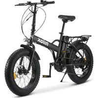
X5 Pro - Electric bike NILOX - Free user manual and instructions
Find the device manual for free X5 Pro NILOX in PDF.


| Product type | Electric assisted bicycle (EPAC) |
| Brand | Nilox |
| Model | X5 Pro |
| Frame | Foldable steel with suspension fork |
| Motor | Rear 36V 250W |
| Battery | Lithium 36V 13Ah (468Wh), removable with lock |
| Range | Up to 70 km (depending on conditions) |
| Maximum speed | 25 km/h (assisted) |
| Assistance levels | 5 levels + walk assistance (6 km/h) |
| Transmission | Shimano 6-speed derailleur |
| Brakes | Mechanical disc brakes with motor cut-off |
| Maximum load capacity | 100 kg (incl. user) |
| Bike weight | Approximately 35 kg |
| Battery weight | Approximately 3.5 kg |
| Charging time | 4 to 6.5 hours |
| Battery recharge cycles | Approximately 700 |
| Charger | 100-240V, red LED (charging) / green (complete) |
| Display | Model G51: speed, distance, assistance level, error codes |
| Lighting | Battery-operated front and rear lights (separate switch) |
| Luggage rack | Yes, steel |
| Handlebar | Adjustable and foldable |
| Saddle | Height adjustable with quick release |
| Pedals | Assembly: right (R) clockwise, left (L) counterclockwise |
| Warranty | 2 years (excluding wear); battery: 12 months |
| Standards | EN15194:2018, directives 2006/42/EC, 2014/30/EU, 2011/65/EU |
Frequently Asked Questions - X5 Pro NILOX
User questions about X5 Pro NILOX
0 question about this device. Answer the ones you know or ask your own.
Ask a new question about this device
Download the instructions for your Electric bike in PDF format for free! Find your manual X5 Pro - NILOX and take your electronic device back in hand. On this page are published all the documents necessary for the use of your device. X5 Pro by NILOX.
USER MANUAL X5 Pro NILOX
Read and follow all instructions in the user manual before using this product. Ensure you understand and follow the safety instructions and warnings to reduce the risk of injury. The user is responsible for all consequences resulting from the improper use of the pedal-assisted bike. Collisions, falls, and loss of control can harm people and objects around the user. In any case, anticipate the trajectory and speed, respecting the traffic code and the most vulnerable road users. The user is responsible for all consequences caused by improper use of the product. The owner of the pedal-assisted bike must check and comply with local laws regarding the use of the product concerning helmet use, speed limits, and accessible areas. The Distributor and Seller are not responsible for any damage to objects and/or people caused by improper use of the product. The obligation to use a helmet is subject to local laws. This product is not a toy. Not suitable for children under 14 years old (check local laws). Adult supervision is recommended for users under 18 years old. This vehicle cannot carry more than one person at a time. This product is not designed for use by persons (including children) with reduced physical, sensory, or mental capabilities, or lack of experience and knowledge of the product, unless they have been given supervision or instruction by a responsible person for their safety. Always check the condition of the wheels and battery before using the product. Keep the battery out of the reach of children.
Cleaning and maintenance cannot be entrusted to children without adequate supervision. Keep the plastic packaging out of the reach of children to avoid suffocation. Children should not play with this product. User cleaning and maintenance cannot be entrusted to children without adequate supervision. Turn off the product and disconnect it from the power supply before performing maintenance or removing the battery. Remove the battery from the vehicle before scrapping it. The product must be turned off and disconnected from the power supply before removing the battery. The battery must be disposed of in accordance with local laws. Read the instruction manual carefully before use. Keep for future reference. Store the manual in a safe place and transfer it to any new owners. The user is responsible for all consequences caused by improper use of the product. Failure to follow the instruction manual may result in loss of control of the product and falls with potentially serious consequences. The Distributor and Seller are not responsible for any damage to objects and/or people caused by improper use of the product. The product is designed to carry one person at a time. Use the product only if in good condition. Losing control of the product during use can have serious consequences for the user and others. Fully charge the battery before using the product. The owner of the pedal-assisted bike must check and comply with local laws regarding the use of the product, concerning helmet use, speed limits, and accessible areas (check current laws). Follow the instructions in this manual to avoid technical problems. The battery is the beating heart of this product. The battery should not be completely discharged and must be fully charged before each use.
Dear Customer, Thank you for choosing a "NILOX" electric pedal-assisted bicycle, entirely designed and assembled in Italy following the international quality standard EN15194:2018 and compliant with directives 2006/42/EC; 2014/30/EU; 2011/65/EU. Electrically Power Assisted Cycles (EPAC) are excluded from the European Directive 2013/168/EU, relating to the approval of two- and three-wheeled motor vehicles, and comply with the requirements prescribed in Article 50 of the Highway Code. This definition excludes the possibility of operating the electric motor independently of pedaling, generally excluding the possibility of moving by activating a throttle. The functional characteristics required by Italian and European regulations for EPAC are as follows.
- the assistance of the electric motor must be provided only when the cyclist pedals in the direction of travel.
• the assistance stops as soon as the cyclist stops pedaling in the direction of travel.
• according to safety standards, the motor assistance stops when the brakes are applied. - the assistance gradually reduces and eventually stops when the vehicle reaches the maximum speed of 25 km/h.
PACKAGING
Open the packaging carefully to avoid damaging the bicycle and remove the protections. In the box, you will find the pedals and the battery charger with the connection cable packed in a plastic bag. Before discarding the packaging, ensure it is completely empty and that all parts of the bicycle are present. It is recommended to keep the complete packaging for a short period. Dispose of the packaging correctly at the appropriate Recycling Centers. The bicycle comes with TWO keys for battery removal. The keys are used to unlock the battery and remove it from its housing and to turn on the bicycle (see the dedicated paragraph). It is advisable to keep one key during the use of the bicycle and store the other in a safe place.
TECHNICAL SPECIFICATIONS
- Foldable steel frame with suspension fork.
• Pedal Assistance from Electric Motor. - Motor: rear 36V*250W.
- Battery: 36V *13Ah (468Wh) Lithium.
• Nominal speed: approx. 25 km/h. - 5 levels of pedal assistance.
- Range: up to 70 km.
- Battery Charger: 100V-240V.
- Charging Time: from 4 to 6.5 hours.
- Battery Charging Cycles: approx. 700.
- Battery Charge Indicator on display.
• Aluminum brake levers with cut-off system. - Mechanical disc brakes.
- Battery Body: removable with Safety Lock.
• Maximum Load Capacity: 100 kg. - Steel luggage rack.
- Adjustable and foldable handlebar.
• Gear: Shimano 6-speed.
• Bicycle weight: approx. 35 Kg. - Battery weight: approx. 3.5 Kg.
USER AND MAINTENANCE MANUAL
The bicycle is defined by the Highway Code as a vehicle, and as such obliges the cyclist to fully comply with the rules governing traffic. PAY ATTENTION TO POSSIBLE NATIONAL LEGISLATIVE REQUIREMENTS WHEN RIDING ON PUBLIC ROADS (for example lighting and reflectors). Gradually familiarize yourself with your bicycle, its equipment, and safety features, and practice until you are sure you can use it correctly.
Knowing the characteristics of your bicycle well and observing common rules of correctness and common sense can help you feel safer during its use. Do not lend the vehicle to those who are not able to handle it. The vehicle must not be used by minors. Ride cautiously; pay attention to other cyclists and distracted motorists. Ride without exceeding your physical limits. Always wear a protective helmet. Periodically check the mechanics of your bicycle. It is advisable to recharge the battery after each use. If not recharged, the battery could be damaged. If the bicycle is not used for long periods, charge the battery at least once a month. Before using the pedal-assisted bicycle, make sure you are operating in absolutely safe conditions. Nuts, bolts, locks, and all mechanical components to be fixed must be closed and not worn and/or damaged. The riding position should be comfortable, carefully spending time adjusting the saddle and handlebar height to ensure a correct riding position. The brakes should be effectively operational. The tires should be inflated to the correct pressure. The pedals should be correctly screwed onto the cranks. Your bicycle has been designed for use on paved and unpaved roads; it is not suitable for off-road use. In any case, extreme uses can be dangerous and entail the exclusive responsibility of the user in the event of any accidents and injuries suffered by him or third parties on such occasions. The manufacturer declines all responsibility for such uses of the product. Your bicycle has been designed to carry one person at a time and to tolerate a total weight of about 100 Kg. The manufacturer declines all responsibility in the event of accidents due to the simultaneous use of the bicycle by more than one person, or due to overload or even luggage not securely fastened to suitable racks. The use of trailers and/or rear carts is prohibited. Have the pedal-assisted bicycle periodically checked to ensure proper functioning. It is the user's responsibility to ensure that all components guarantee the correct functioning of the bicycle. It is important to keep the braking system always efficient and clean from impurities accumulated during road use. The user is warned that he assumes personal risk for injuries, damages, and/or losses if the above conditions are violated and the warranty will automatically expire. Uses different from those for which the EPAC was designed, as well as any intervention that modifies the functioning of your EPAC, as described, are prosecutable and punishable by law and expose you to the risk of damage or injury. In no case can the manufacturer be held responsible for accidents or damages resulting from non-compliant uses of the EPAC, or deriving from modifications or interventions made on it.
RULES FOR CIRCULATION
Check that the battery is securely fixed in its housing and locked with the supplied key. Check that the brakes work correctly. Check that the lighting devices work correctly. By law, the speed of the bicycle during use assisted by the electric motor cannot exceed 25 km/h. In case of fords, check that the water level does not reach the height of the electric motor. Do not pedal during braking. Avoid continuous braking and restarting to prolong battery life. Ride safely. Always wear a cycle helmet compliant with regulation (EU) 2016/425. Pay attention to traffic rules. Increase the speed of pedal assistance progressively. Keep pedal assistance active on uphill paths or dirt roads to prolong battery life and motor efficiency. Pay attention to tire pressure and circulation along wet, slippery, dirty paths, and in any case with poor grip; if you encounter the indicated cases, ride slowly or push the bicycle. The maximum load capacity (including the user) is 100 Kg, do not exceed the capacity. At the end of the use of the electric bicycle. Turn off all switches (first turn off the display and then the battery). Do not leave the bicycle exposed to humidity, rain, or excessive heat. Never subject the bicycle to continuous water jet washing. Do not cover the bicycle with plastic covers.
WARNING
The electric motor of the Bicycle also works as a current generator. We recommend keeping the above in mind and in case of using the Bicycle downhill, if the slope is steep, slow down the pace by keeping the Bicycle braked. Besides being a safety issue for the Driver, it will prevent the development of high voltage capable of burning the electric control unit.
OPERATION OF THE PEDAL-ASSISTED BICYCLE
This is a PEDAL-ASSISTED BICYCLE. This means that, even if equipped with an electric motor, the user must pedal like on a normal bicycle for it to function. The electric motor assists the pedaling, making it less tiring and increasing its speed. The bicycle can also be used without motor assistance. The maximum speed achievable with the pedal-assisted bicycle is 25 Km/h. To activate pedal assistance, it is necessary to turn on the bicycle via the switch on the battery and then press the ON/OFF button
on the display; the light indicators on the handlebar display will turn on to indicate that the battery is charged and the bike is ready for use. As the bicycle is used and the battery loses charge, the lights will turn off one by one. Starting to pedal activates the control unit that allows the motor to assist the pedaling. The supplied Shimano 6-speed gear allows further adjustment of the pedaling ratio according to your needs. Pedal assistance stops in case of braking or if you stop pedaling (for example downhill). To reactivate it, simply start pedaling again. During braking, please do not pedal. The indicated autonomy is to be understood with normal use of a bicycle on city and/or town routes. In case of steep climbs and/or carrying heavy objects, the autonomy could significantly decrease. As already specified, being a bicycle, the addition of an accelerator is not foreseen. The user's decision to introduce an accelerator will immediately void the bicycle's warranty and would cease its nature as a bicycle. When riding a pedal-assisted electric bicycle, your speed is significantly higher than that of a "normal bicycle." Pay more attention and consider adequate braking spaces.
THE BICYCLE
The bicycle is supplied open with the saddle mounted and the handlebar turned. The pedals need to be mounted. The battery is not connected. To insert and connect it correctly, refer to the "positioning" paragraph. Remove the protections, then straighten and adjust the handlebar.
- Raise the handlebar tube and bring it to a vertical position.
- Close the locking lever.
• Turn the safety ring until it locks in the lever.
• To adjust the handlebar height, act on the quick release and raise and/or lower the "T" bend. - To fold the handlebar, release the safety ring and open the lever downwards; lower the handlebar to the right of the frame towards the pedal, paying attention to the brake and gear cables. Make sure to close all locks well before using the bicycle.
PEDAL ASSEMBLY
Screw the pedals onto the cranks: the RIGHT pedal is marked, on the pin, with the letter "R"; screw this pedal CLOCKWISE onto the RIGHT crank (chain side). The LEFT pedal is marked, on the pin, with the letter "L"; screw this pedal COUNTERCLOCKWISE onto the LEFT crank. Initially screw the pedals by hand, then tighten with the wrench until, without forcing excessively, you reach the end. WARNING: follow the instructions scrupulously to avoid damaging the pedal and/or crank threading. In case of any anomaly in the pedal movement during use, immediately stop pedaling and have the bicycle checked by a competent mechanic.
SADDLE ADJUSTMENT
Correct saddle adjustment is important for body position during pedaling and allows you to achieve the best performance with less stress on the joints. Before use, try the bicycle and adjust the saddle height and angle. The saddle height should be adjusted according to the length of the legs. The height is correct if, when seated, you reach the pedal in the lowest position with your heel. The leg must be completely straight. Adjust the height according to these indications. In height adjustment, always respect the STOP mark present on the seat post. THE MARK MUST ALWAYS BE INSERTED INTO THE FRAME TUBE. If you wish to keep the saddle not completely horizontal but with the "nose" slightly raised, you must loosen the lock under the saddle and adjust the angle. Tighten the lock again to prevent the saddle from moving. Changes in saddle position, even if small, can affect comfort during pedaling. It is recommended, whenever you want to make an adjustment, to make only one change at a time and progressively until you find the most comfortable and correct position. Ensure that the clamp nuts that adjust the saddle position are well tightened. The bicycle is equipped with a quick-release seat post lock; to adjust the saddle, open the lock, raise or lower the seat post to the desired height ensuring that the stop limit is not visible, tighten the quick-release mechanism, and ensure the lever is well tightened.
BRAKE ADJUSTMENT
The bicycle is equipped with MECHANICAL DISC brakes. The disc brake pads need minimal wear before reaching optimal braking. Additionally, the discs heat up when in action, do not touch them after just
stopping. In case of breakage of one of the two braking systems, immediately proceed with the repair, as one brake alone is not sufficient to ensure safe braking. A thorough check of the pads, sheaths, and tension cables and their lubrication is recommended; if you notice frayed or stretched spirals, curved ends, rust, or wear, promptly replace the damaged parts. To replace the pads, loosen the retaining bolt until the pad is removed and proceed with the replacement. Check that the brake pads are securely fixed (tightening 5/8 Nm). If possible, have these operations performed by qualified personnel.
GEAR ADJUSTMENT
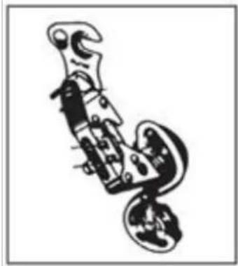
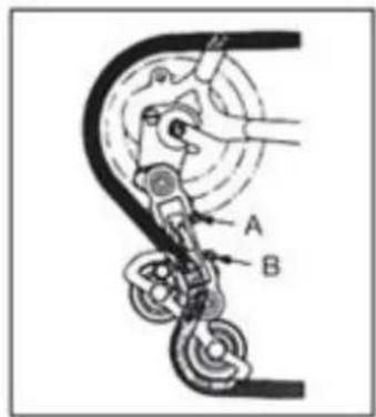
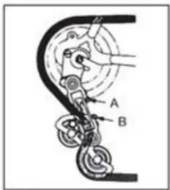
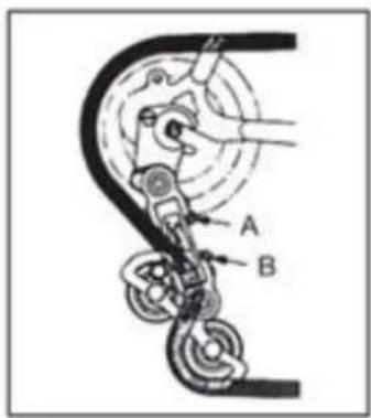
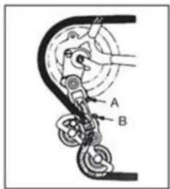
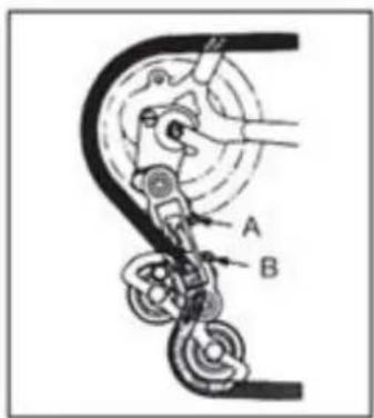
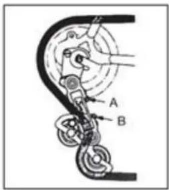
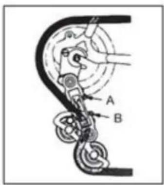
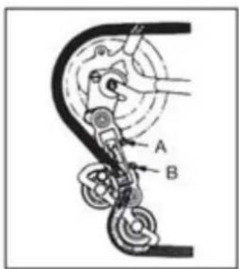
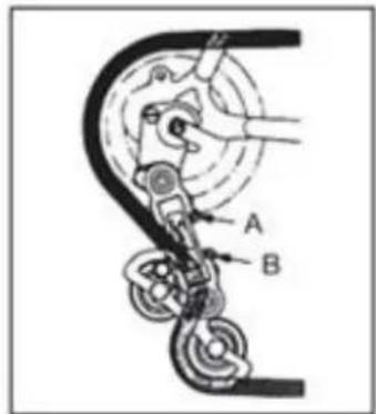
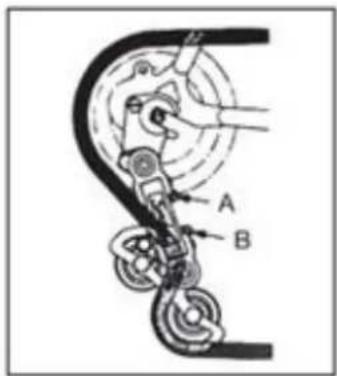
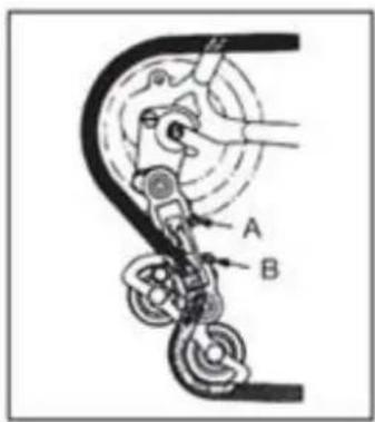
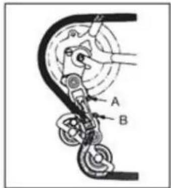
If the chain has difficulty climbing onto the large rear sprocket (gear control on the handlebar turned to the maximum), slightly unscrew the B screw, avoiding the chain going beyond the last sprocket. If the chain descends with difficulty onto the small rear sprocket, slightly unscrew the A screw to align the derailleur group on the small sprocket. In case of doubts or any anomaly during use, have the bicycle checked by a competent mechanic.
WHEEL ASSEMBLY WITH HUB WITHOUT QUICK RELEASE
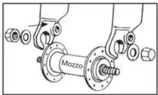
Insert the front wheel hub into the fork; insert the two anti-fall washers, one on each side, ensuring that the tooth fits into the appropriate hole on the fork. Insert and tighten the two nuts, ensuring that the wheel is centered in the fork. WARNING: before using the bicycle, always check that the wheel is correctly locked to the front fork and the rear dropouts of the frame. In case of doubts or any anomaly during use, have the bicycle checked by a competent mechanic.
FRONT AND REAR LIGHT
The bicycle is equipped with a battery-powered front and rear light system. Both the front and rear lights are turned on directly by pressing the switches on the light.
HOW TO USE THE BICYCLE
This electric bicycle is equipped with a "pedal assist system," consisting of a motor, a battery, and a pedal sensor. It is important to know that when the system is on, the motor provides power only while pedaling. When you stop pedaling, the motor disengages and the electric pedal assist ceases. In all pedal-assist bicycles, the motor also disengages and the electric assist stops when the maximum
speed allowed for electric bicycles of 25 Km/h is reached. When the speed drops below this value, the electric assist resumes until you stop pedaling.
Even when using the brakes, the electric assist stops.
TURNING ON THE BICYCLE
Ensure that the battery key is in the "ON" position. Turn on the bicycle by pressing the "ON/OFF" button on the display. Start pedaling to activate the pedal assist. It is recommended to start slowly and gradually increase the pedaling speed. The motor only engages while pedaling; stopping pedaling or braking will stop the motor.
TURNING OFF THE BICYCLE
Turn off the bicycle by pressing the "ON/OFF" button on the display. Turn the battery key to the "OFF" position. Ensure that the bicycle is turned off when not in use. It is recommended to disconnect the battery.
DISPLAY (The display may vary depending on the chosen configuration).
MODEL G51
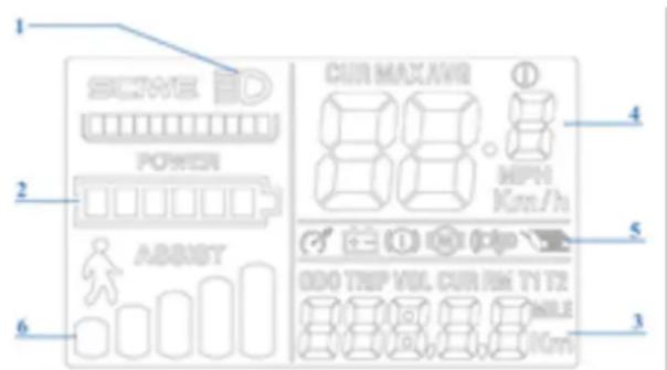
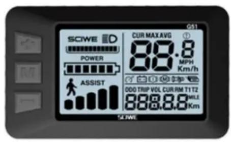
The bicycle is equipped with five levels of pedal assist, selectable on the display.
With the display, you can turn on the bicycle, adjust the pedal assist, and view the following information:
- Light control (if provided by the bicycle configuration).
- The remaining battery charge.
- The distance traveled (TRIP), the total distance traveled (ODO), and the usage time (TM).
- The cruising speed (SPEED), the average speed (AVG), and the maximum speed reached (MAX).
- Error codes (REE).
- The selected assist level or the activation of the "WALK_EASY START" function.
By turning on the motor via the "M" button, the pedal assist system is activated. The assist level is preset to "1". To change it: start pedaling and stabilize the speed; press the "+" or "-" buttons on the display to adjust the assist to the desired level (from 1 to 5). "WALK_EASY START" function: Allows you to push the bicycle by hand in pedestrian areas, reducing the weight to be pushed. The motor activates an automatic function for a cruising speed of up to 6 km/h.
- Power button "M" _ TURNS THE BICYCLE ON AND OFF (the display will automatically turn off after a few minutes of inactivity).
- Buttons "+" and "-" SELECT THE PEDAL ASSIST.
- While pedaling, press the "M" button to access the information in area "3".
- To activate the "WALK_EASY START" function, press and hold the "-" button. The bicycle must be stationary and accompanied by hand. The icon on the display indicates that the function is active.
BATTERY CHARGE INDICATION ON THE DISPLAY
When the bicycle motor is turned on and you start pedaling, the icon ("2") on the display indicates the instant charge measured and not the actual available charge. In case of uphill routes, when the motor is more stressed, the indicator may show a reduced residual charge (the number of bars on the display decreases). When the motor is stationary, in case of stopping or moving by inertia (for example, downhill), the indicator may show a greater available charge. Therefore, the best time to realize the residual charge amount is when reaching a constant speed on a flat and straight path after stabilizing the battery's work.
RANGE
The range of the bicycle with pedal assist can vary depending on different usage conditions and different weights to be transported. It is estimated to be around 40-70 km (depending on the chosen configuration) and is intended for normal use of a bicycle with medium pedal assist on predominantly flat urban routes. However, the electric motor will absorb more power in case of steep climbs, heavy object transport, headwind, as well as repetitive stops and starts, significantly reducing the normally achievable distances.
ERROR CODES
2: brake issue.
3: sensor issue.
4: issue with the "WALK_EASY START" function.
5: speed indication error.
6: low battery.
7: motor issue.
9: control unit issue.
10: communication error.
11: communication error.
LITHIUM BATTERY
At the end of each use of the bicycle or if the battery is low, proceed to recharge the battery.
• After prolonged use, the battery capacity will slowly decrease.
- Do not leave the battery discharged for a long time (max. 10 days).
- In case of prolonged bicycle inactivity, charge the battery at least once a month to avoid compromising its functionality.
• The battery must be kept out of reach of children.
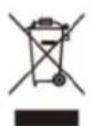
- The crossed-out container indicates that batteries cannot be disposed of in urban waste or abandoned in the environment. Batteries are subject to special collection and must therefore be delivered to the appropriate Recycling Centers.
• Excessive heat damages batteries; therefore, avoid sun exposure.
- Avoid batteries from being hit.
- OFF: bicycle off.
• ON: bicycle on and functioning; the display can be turned on.
- PUSH: press to then position the key on UNLOCK.
- UNLOCK: unlocks the battery and allows it to be removed from its housing.
REMOVING THE BATTERY
- Ensure that the bicycle is firmly on the stand.
- Completely remove the seat post.
- Turn the key to "push" and push it into the lock.
- Simultaneously turn the key to "UNLOCK" to unlock the battery.
- Pull the battery upwards to remove it.
POSITIONING THE BATTERY
- Ensure that the bicycle is securely on its stand.
- Insert the battery into its compartment and push it firmly downwards.
- Turn the key to OFF or ON if you want to use the bicycle.
- Insert the seat post and make sure to lock it correctly.
BATTERY CHARGE STATUS DISPLAY
You can check the remaining battery charge by pressing the dedicated button on the battery.
BATTERY CHARGING TIMES
The battery is supplied partially charged. Fully charge the battery before first use. A full charge of the lithium battery typically takes 6.5 hours.
Never leave the battery charging for entire days or nights exceeding the maximum time of 6 hours. The battery could be damaged. When the bicycle is turned on, you can check the remaining charge status by pressing the button next to the indicators. The LEDs light up as follows.
• 4 LEDs on: 100% remaining charge.
• 3 LEDs on: 70% remaining charge.
• 2 LEDs on: 40% remaining charge.
- 1 LED (red) on: up to 15% remaining charge (the battery needs to be recharged as soon as possible).
BATTERY CHARGING
At the end of each use of the bicycle, it is advisable to always recharge the battery. Keeping the battery always charged extends its lifespan. It is necessary to use the supplied charger and follow the instructions provided on it. Do not use other chargers that are not approved by the manufacturer and/or distributor. They could damage the battery and shorten its lifespan. Using personal accessories not supplied with the bicycle will automatically void the legal warranty.
The battery can be charged either while it is on the bicycle or after removing it. Before charging the battery, carefully read the following instructions and follow them during the process.
- Use only the supplied charger.
- Keep both the charger and the battery away from children and pets.
- The charging operation must be carried out in a spacious, cool, and dry place; away from direct heat sources and humidity.
- If charging with the battery housed in the bicycle, ensure that it is securely and stably on its stand and turned off.
• It is normal for the charger to heat up during charging. - Do not cover the charger.
- Keep the charger and battery plugs and connectors clean and dry.
- Do not wet the charger.
- Do not use the charger and/or battery if they appear damaged.
• Always connect the charger to the battery first and then to the power outlet. - Do not charge under direct sunlight.
- Do not use the charger for other purposes or devices.
• Voltage drops during charging cycles could damage the battery.
• Always connect the charger to the battery first and then to the power outlet.
• Always remove the charger from the battery after charging.
HOW TO CHARGE THE BATTERY
The battery can be charged either while it is on the bicycle or after removing it.
- Place the battery near a power outlet.
- Turn the disc on the side of the battery clockwise or counterclockwise.
- Connect the charger.
-
Place the charger on the ground or on a flat, non-slip surface and connect it to the power outlet.
-
Connect the charger to the power outlet.
- There is an LED indicator on the charger. The LED is red when the battery is connected to the power and is charging.
- When fully charged, the charge status light will turn green.
- Disconnect the charger from the power outlet, then remove the plug from the battery.
- If previously removed, reinsert the battery into its compartment in the bicycle.
CHARGER MAINTENANCE
- When the battery charge is complete, first disconnect the cable from the 220V power outlet and then the battery power cable.
• Store the charger in a dry and clean environment.
• The charger does not require any maintenance. Any opening or tampering is prohibited.
• In case of malfunctions, contact the Service Center. - If the cable is damaged, replacement must be done by a Service Center.
- If the charger's temperature rises too high (over 65°C), an unpleasant odor will be noticeable: immediately stop charging and contact the Service Center.
Even if properly maintained, the rechargeable battery is not eternal. Each time the battery is discharged and recharged, its capacity decreases by a very small percentage. You can extend the battery life by carefully following the provided charging instructions. The lithium battery has no "memory." Partially discharging and recharging the battery does not affect its performance or lifespan. Therefore, it is possible to recharge the battery even if it is not completely discharged. If the bicycle is not used for a long period, keep the battery charged at least once a month, leaving it to charge for about 4 hours. In this case, do not pay attention to the charger lights. When the battery is completely discharged, it must be recharged immediately. Do not leave the battery discharged and unused but proceed immediately with a charging cycle. In this case, perform a longer charging cycle, about 6 hours, to allow the battery to fully activate. Once or twice a year, it is recommended to use the bicycle until the battery is completely discharged. Then fully charge it. This process has a beneficial effect on the battery's lifespan.
MAINTENANCE AND CLEANING
Technological advances have made the E-Bike and its components more complex than in the past, and the pace of innovation is increasing. With this continuous evolution, it is essential to contact an authorized service center for any mechanical and/or electrical repairs and/or maintenance. For routine maintenance and cleaning, follow these guidelines.
TIGHTENING BOLTS AND NUTS
During use, some screws may loosen due to vibrations. We recommend periodically checking the tightness of the screws. Immediately replace any damaged or lost parts. The following is a tightening table to be applied for assembling different types of components. For each component, the "minimum-maximum" range to which those components should generally be tightened is indicated. The table is purely indicative, as numerous variables affect the precise degree to be applied to the various screws, such as the material used for the screw and/or the type of threading, the sections and thicknesses of the material being worked on, and naturally the material of the parts to be interfaced. The tightening torques are expressed in Newton-meters; remember that to perform this operation correctly, a torque wrench is necessary, which disengages when the desired torque is reached.
- Front hub nut: 20 - 27 Nm.
- Rear hub nut: 27 - 33 Nm.
- Seat clamp: 7 - 22 Nm.
- Brake on frame: 10 Nm.
- Brake pad: 8 Nm.
- Brake cable: 5 Nm.
- Gear cable: 5 – 6 Nm.
-
Seat post bolt: 10 - 14 Nm.
-
Handlebar expander bolt: 18 - 20 Nm.
- Derailleur on hanger: 12 – 15 Nm.
- Front derailleur bolt: 5 - 7 Nm.
• Disc brake caliper bolt: 6 - 8 Nm. - Handlebar stem on fork: 5 - 8 Nm.
- Handlebar stem on bar: 5 - 8 Nm.
• Controls on handlebar: 10 Nm. - Crankset bottom bracket: 32 – 50 Nm.
• BSA bottom bracket cups: 70 Nm.
• Pedals: 34 - 40 Nm.
BREAK-IN PERIOD
Your bicycle will be more efficient and remain in optimal condition for a long time with a break-in period before continuous and intensive use. Brake or gear cables, spokes, and other mechanical parts may loosen in the very first period of use, and a visit to the service center may be necessary for final adjustments. We suggest, after 30/35 hours of use and in any case after the first 30 days, to have the electric bicycle checked at a service center. In any case, for any problem or doubt that you cannot solve on your own, always contact the specialized technical service center and do not use the bicycle in case of real or presumed anomalies. It is advisable to check the mechanics before each use. After each long or difficult ride on rough terrain, in case of exposure to water or sand, and in any case every 150 km, proceed as follows.
- Clean the bicycle.
- Lubricate the chain, freewheel, and derailleur, then remove excess oil. You can ask your trusted technician for advice on the best lubricants on the market and the frequency of maintenance.
- Pull the front brake and move the bicycle back and forth to ensure everything is in order. If you hear a dull noise with each movement, there may be steering problems: contact the service center.
- Lift the front wheel off the ground and turn it left and right to ensure smooth steering. If the steering is stiff, there may be steering problems: contact the service center.
- Ensure that nuts, bolts, clamps, and all mechanical components are tight and not worn and/or damaged.
The bicycle and its mechanical components are subject to wear. The materials they are made of have different life cycles. It is recommended to periodically check, or at least once a year, the bicycle to assess its proper functioning and the wear status of the components, and if necessary, proceed with the replacement of worn/malfunctioning components.
FLAT TIRE
Do not use the bicycle in case of a flat or partially deflated tire. Walk the bike. In case of a tire puncture, release the wheel from the hub to remove it and deflate the tire. Remove the tire, possibly using a tire lever to extract it from the rim. Remove the punctured inner tube and replace it. Slightly inflate the tube and reposition the tire on the rim, over the tube. Be careful not to pinch the new inner tube between the rim and the tire. Spin the wheel to ensure that the entire tire is correctly positioned on the rim and that the tube is completely inside it. Slowly inflate to the recommended pressure, checking the tire's position on the rim. Reposition the wheel.
In case of difficulty, contact the service center for replacement. It is recommended to use only a tire lever for this operation. Otherwise, using a screwdriver or any other tool, you risk puncturing the inner tube.
CLEANING THE BICYCLE
Dust the frame with a soft cloth, remove dirt with a damp cloth and non-abrasive cleaner. Do not use high-pressure cleaners. Carefully dry all parts and periodically apply car wax. Clean plastic parts and tires with water and soap, dry thoroughly. If used during humid or rainy days, dry the bicycle thoroughly before parking it. Do not leave the bicycle exposed to moisture, rain, direct sunlight. If it is not possible to shelter it, cover it with a dark waterproof tarp. Salt is highly corrosive. If you live or use the bicycle
in coastal areas, it is recommended to wash the bicycle very often to remove the salt, always dry thoroughly and apply anti-rust on unpainted parts. Periodically grease the bottom bracket, freewheel, chain, and other parts that need it. Periodically check screws, nuts, bolts, and locks to ensure they are tightly fastened.
STORING THE BICYCLE
Keep the bicycle in a dry and covered place, avoiding direct exposure to sun, weather, and salt. If you plan not to use the bicycle for a long period, before parking it, perform a complete and thorough cleaning. Deflate the tires halfway and, if possible, hang the bicycle and cover it with a preferably cotton tarp. Do not use plastic tarps. Recharge the battery and keep it charged once every two months to prevent it from completely discharging. Ensure the charger is not connected to either the power or the bicycle. The recommended storage temperature for the lithium battery is between 0°-25°. Avoid storing the battery in places that are too cold or too hot. Do not expose the battery to heat sources (+35/40°) for long periods. Do not leave the battery with condensation build-up that could damage, cause a short circuit, or corrode the battery.
WARRANTY
The provided warranty is two years from the date of purchase except for parts subject to wear. The warranty does not cover parts normally subject to wear, damage caused by impacts, poor care, disassembly, or tampering with parts arbitrarily performed by the User, failure to comply with the instructions in the booklet regarding maintenance and repair of the vehicle. Any problems with warranty parts must be submitted exclusively to the Dealer, and the vehicle must be accompanied by its warranty. We remind you that only pedal-assisted bicycles are considered electric bicycles. Any tampering or modification to the product will immediately void the vehicle's warranty, as well as cease its bicycle characteristics and significantly reduce the battery's autonomy. The bicycle warranty does not cover paint damage, rust, corrosion, or theft. A 12-month warranty is provided for the bicycle battery, subject to correct use and maintenance indicated in the manual. The warranty will not be recognized if the batteries are deemed exhausted, at the end of their cycle, and/or not correctly charged. The warranty request will be evaluated by the manufacturer.
PRODUCT DISPOSAL
At the end of its life cycle, this product must not be disposed of with household waste. Its disposal must be carried out separately, according to local recycling laws and regulations.
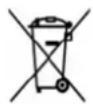
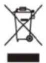
For more information on systems for separate collection of waste electrical and electronic equipment, contact the local municipal authority. In this case, the product will be disposed of in an environmentally friendly manner at an authorized recycling facility, and its components will be recovered, recycled, and reused as efficiently as possible in accordance with the requirements of the Waste Electrical and Electronic Equipment Directive (2002/96/EC) of January 27, 2003. In accordance with environmental regulations, it is mandatory to use separate collection systems for waste electrical and electronic equipment. Note: waste electrical equipment may contain hazardous substances that, if improperly disposed of, can be harmful to the environment and human health. Therefore, it is essential to proceed with specific disposal of waste electrical and electronic equipment. The crossed-out wheeled bin symbol (shown below) is affixed to all electrical and electronic equipment placed on the market. The symbol indicates that, at the end of their life cycle, these products must be disposed of separately from other waste to ensure their complete recovery and environmentally friendly disposal.
NOTE
The Company reserves the right to make changes to both the text and the products without any notice. The graphical representation of the products (images and descriptions) is made solely for the purpose of illustrating the product and is purely indicative.
ASSISTANCE
Contact your Dealer or select the "Product Assistance" option on the Nilox Website.
IMPLEMENTATION OF DIRECTIVE 2006/66/EC
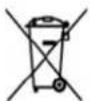
The product operates with batteries that fall under the European Directive 2006/66/EC and cannot be disposed of with normal household waste. Learn about local regulations regarding separate collection of batteries: proper disposal helps prevent negative consequences for the environment and health. The battery is to be disposed of at the end of the product's useful life. Recovery and recycling centers can perform the disassembly of the product and removal of the battery.
PROPER BATTERY DISPOSAL
Pursuant to Legislative Decree No. 49 of March 14, 2014 "Implementation of Directive 2012/19/EU on waste electrical and electronic equipment (WEEE)".
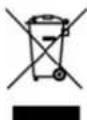
The crossed-out wheeled bin symbol on the equipment indicates that the product, at the end of its useful life, must be collected separately from other waste. The user must, therefore, deliver the equipment intact with essential components at the end of its life to suitable separate collection centers for electronic and electrical waste, or return it to the retailer when purchasing new equipment of equivalent type, on a one-to-one basis, or one-to-zero for equipment with a major side less than 25 cm. Proper separate collection for subsequent recycling, treatment, and environmentally compatible disposal helps prevent possible negative effects on the environment and health and promotes the recycling of materials that make up the equipment. Illegal disposal of the product by the user entails the application of administrative sanctions as per Legislative Decree No. 49 of March 14, 2014.
DECLARATION OF CONFORMITY
It is declared that the described product complies with the EMC Directive 2014/30/EU; LVD Directive; MD Directive; RoHS Directive. The images in this manual are purely for illustrative purposes. The Company disclaims any responsibility for improper use of the product. The Company reserves the right to make changes in technology, equipment, and the user manual without notice.
MADE IN CHINA
CE
Esprinet S.p.A. Via Energy Park 20 – 20871 Vimercate (MB) - Italy www.nilox.com
For info write to: contact@esprinet.com
nilox
ITALIANO - IT
ÉLIMINATION DU PRODUIT
DÉCLARATION DE CONFORMITÉ
Vstavite os sprednjega kolesa v vilice; vstavite dve podložki z zobom proti padcu, eno na vsako stran, pri tem pazite, da se zob vstavi v ustrezno luknjo na vilicah. Vstavite in zategnite dva vijaka, pri tem pazite, da je kolo na sredini vilic. POZOR: pred uporabo kolesa vedno preverite, ali je kolo pravilno pritrjeno na sprednje vilice in zadnje vilice okvirja. V primeru dvomov ali zaznave kakršne koli anomalije med uporabo naj kolo pregleda usposobljen mehanik.
SPREDNJA IN ZADNJA LUČ
WDROŻENIE DYREKTYWY 2006/66/WE
WYPRODUKOWANO W CHINACH
CE
Esprinet S.p.A.
Via Energy Park 20 - 20871 Vimercate (MB) - Włochy
www.nilox.com
ELIMINAREA PRODUSULUI


- PACKAGING
- TECHNICAL SPECIFICATIONS
- USER AND MAINTENANCE MANUAL
- RULES FOR CIRCULATION
- WARNING
- OPERATION OF THE PEDAL-ASSISTED BICYCLE
- THE BICYCLE
- PEDAL ASSEMBLY
- SADDLE ADJUSTMENT
- BRAKE ADJUSTMENT
- GEAR ADJUSTMENT
- WHEEL ASSEMBLY WITH HUB WITHOUT QUICK RELEASE
- FRONT AND REAR LIGHT
- HOW TO USE THE BICYCLE
- TURNING ON THE BICYCLE
- TURNING OFF THE BICYCLE
- BATTERY CHARGE INDICATION ON THE DISPLAY
- RANGE
- ERROR CODES
- LITHIUM BATTERY
- REMOVING THE BATTERY
- POSITIONING THE BATTERY
- BATTERY CHARGE STATUS DISPLAY
- BATTERY CHARGING TIMES
- BATTERY CHARGING
- HOW TO CHARGE THE BATTERY
- CHARGER MAINTENANCE
- MAINTENANCE AND CLEANING
- TIGHTENING BOLTS AND NUTS
- BREAK-IN PERIOD
- FLAT TIRE
- CLEANING THE BICYCLE
- STORING THE BICYCLE
- WARRANTY
- PRODUCT DISPOSAL
- NOTE
- ASSISTANCE
- IMPLEMENTATION OF DIRECTIVE 2006/66/EC
- PROPER BATTERY DISPOSAL
- DECLARATION OF CONFORMITY
- NILOX
- ITALIANO - IT
- ÉLIMINATION DU PRODUIT
- DÉCLARATION DE CONFORMITÉ
- SPREDNJA IN ZADNJA LUČ
- WDROŻENIE DYREKTYWY 2006/66/WE
- ELIMINAREA PRODUSULUI
Brand : NILOX
Model : X5 Pro
Category : Electric bike