
TE-50 - Trash can FRANKE - Free user manual and instructions
Find the device manual for free TE-50 FRANKE in PDF.

| Product Type | Food Waste Disposer |
| Brand | Franke |
| Model | TE-50 |
| Intended Use | Domestic, under-sink installation |
| Supply Voltage | 220-240 V ~, 50/60 Hz |
| Motor Power | 0.75 HP (560 W) |
| Feed Type | Continuous (default) or batch (with stopper) |
| Dimensions | Height: 340 mm, Diameter: 180 mm |
| Weight | 7 kg |
| Grinding Chamber Material | Stainless steel (turntable) |
| Chamber Capacity | 1.2 L |
| Anti-Jam System | Anti-jam pivoting rotors |
| Reset Button | Yes, red, located under the unit |
| Dishwasher Connection | Yes, via connection on disposer |
| Removable Splash Guard | Yes |
| Maintenance | Self-cleaning, do not lubricate |
| Grounding | Required, cord with grounding plug |
| Warranty | See manufacturer's conditions |
| Spare Parts Available | Stopper, splash guard, gaskets, discharge elbow |
| Repairability | Accessible reset button, professional replacement recommended |
Frequently Asked Questions - TE-50 FRANKE
User questions about TE-50 FRANKE
0 question about this device. Answer the ones you know or ask your own.
Ask a new question about this device
Download the instructions for your Trash can in PDF format for free! Find your manual TE-50 - FRANKE and take your electronic device back in hand. On this page are published all the documents necessary for the use of your device. TE-50 by FRANKE.
USER MANUAL TE-50 FRANKE
natural_image
Technical line drawing of a mechanical device with no visible text or symbols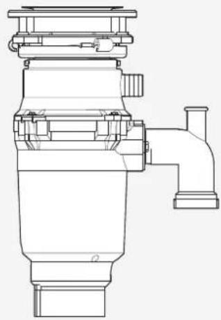
natural_image
Technical line drawing of a mechanical pump or valve assembly (no text or symbols)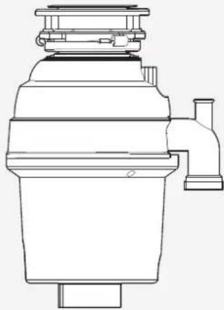
natural_image
Technical line drawing of a mechanical device with no visible text or symbolsCE-50
TE-50
TE-75S
TE-125BF
CE-75
TE-75
TE-125
EN User and installation manual
Removal of old unit 6
Plumbing connection 7
Installation of mounting assembly 7
Electrical connection 9
Attaching discharge elbow 10
Air switch operated 11
Operating instructions 11
Continuous feed 11
Batch feed 11
Troubleshooting 12
Cleaning and Maintenance 13
Disposal 13
ABOUT THIS MANUAL
This user manual applies to several models of the device. Thus it may be possible that some of the described features and functions are not available on your specific model.
FRANKE reserves the right to make modifications to the product without prior notice. All information correct at time of issuance.
▶ Keep the user manual.
▶ Use the device described in this user manual only according to the intended use.
INTENDED USE
The food waste disposer is an electrical device to be installed under the sink in order to shred food waste into pieces.
Symbol Meaning

Warning symbol. Warning against risks of injury.
▶ Actions in safety and warning notes to avoid injury or damage.
▶ Action step.
Specifies an action to be done.
■ Result. Result of one or more action steps.
√ Precondition that has to be fulfilled before performing the following action.
SAFETY INFORMATION
INSTRUCTIONS PERTAINING TO A RISK OF FIRE, ELECTRIC SHOCK OR INJURY TO PERSONS.

WARNING: When using electrical appliances, basic precautions should always be followed, including the following:
▷ Read all instructions before using the appliance.
To reduce the risk of injury, close supervision is necessary when an appliance is used near children.
Do not put fingers or hands into a waste disposer.
▷ Turn the power switch to the off position before attempting to clear a jam or remove an object from the disposer.
When attempting to loosen a jam in a waste disposer, use a long wooden object such as a wooden spoon or the wooden handle of a broom or mop.
▷ When attempting to remove objects from a waste disposer use long-handled tongs or pliers. If the disposer is magnetically actuated, non-magnetic tools should be used.
Make sure that the authorities permit the installation of the waste disposer.
▷ Use the waste disposer only for food waste.
To reduce the risk of injury by materials that may be expelled by a waste disposer, do not put the following into a disposer: clam or oyster shells; caustic drain cleaners or similar products; glass, china or plastic; large whole bones; metal, such as bottle caps, tin cans, aluminum foil or utensils; hot fat or other hot liquids; whole corn-husks.
▷ When not operating a disposer, leave the stopper in place to reduce the risk of objects falling into the disposer.
DO NOT operate disposer unless splash guard is in place.
For proper earthing instructions see the ELECTRICAL CONNECTIONS portion of this manual.
This Food Waste Disposer has been designed to operate on 220-240V\~, 50/60 Hz exclusively. Using any other voltage or Hz adversely affects performance.
The receptacle to which this appliance is connected must be controlled by a switch.
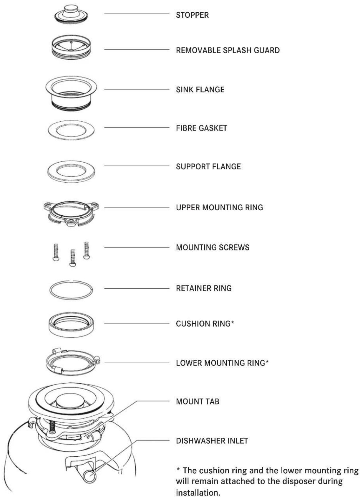
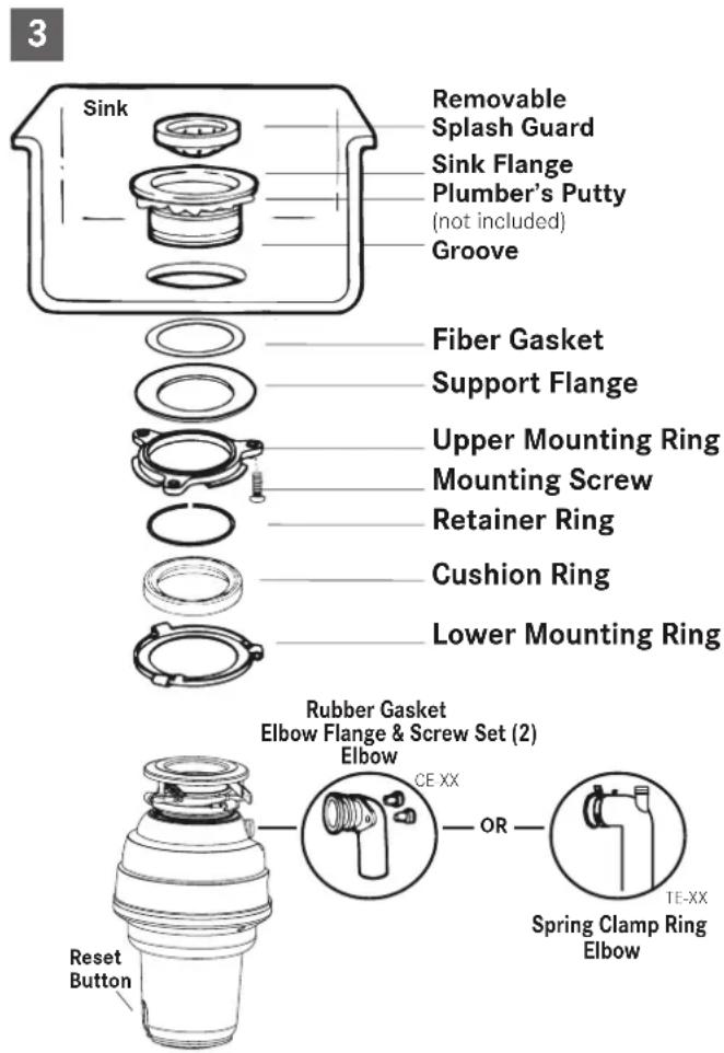
ASSEMBLY PARTS
REMOVAL OF OLD UNIT
TYPICAL INSTRUCTIONS, YOUR MODEL MAY VARY.
▷ Before starting this step, turn off electrical power at the circuit breaker or fuse box.
▷ Unplug disposer.
If your old mount is the same type as the mount on your new disposer, just reverse the assembly instructions found in INSTALLATION OF MOUNTING ASSEMBLY. If your new mount system is different, follow these instructions:
▶ Have a container available to catch any excess water / waste from current disposer.
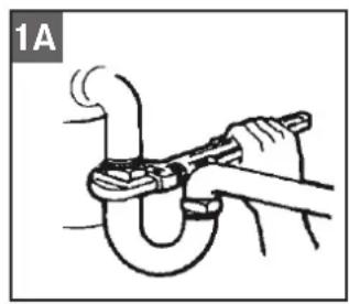
▶ Use a pipe wrench to disconnect drain line where it attaches to disposer discharge elbow (fig. 1A).
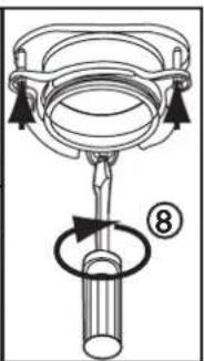
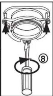
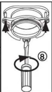
▶ Remove disposer from sink flange by turning mounting ring to the left clockwise (fig. 1B). If you are unable to turn the mounting ring, tap on one of the extensions from the ring with a hammer. Some mounting systems have tubular extensions. Inserting a screwdriver into one tube will provide additional leverage for turning the mounting ring (fig. 1B). Some disposers may require the removal or loosening of nuts from the mounting screws (fig. 1C). Some disposers may require the removal of a clamp.
CAUTION: Be sure to support the disposer while performing this step or it may fall when the mounting ring is disconnected from the mounting assembly.
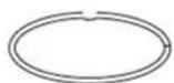
▶ To remove remaining mounting system from the sink, loosen the screws, push mounting ring up. Under it is the snap ring. Use screwdriver to pop off ring (fig. 1D). Remove the mounting ring, protector ring and gasket from sink flange. Some mounts will require the unscrewing of a large ring holding the sink flange in place. Pull sink flange up through sink and clean off old putty from sink.
▶ Ensure that sink is clean and thoroughly dry.
IMPORTANT: This is a good time to clean out the trap and drain lines by running a drain auger or plumber's snake before installing your new disposer.
natural_image
Illustration of a hand using a tool to tie a U-shaped pipe knot (no text or symbols)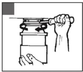
natural_image
Illustration of a hand using a tool to lift a cylindrical object (no text or symbols present)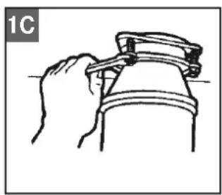
natural_image
Line drawing of a hand gripping a mechanical component (no text or symbols)
natural_image
Line drawing of two hands holding a circular object with a ring, no text or symbols presentPLUMBING CONNECTION
If dishwasher and/or overflow is not to be connected go on to next section.
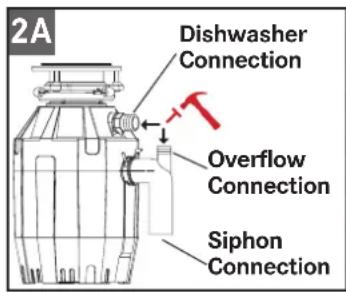
If you are utilizing a dishwasher, this should preferably be connected directly to the relevant connection in the siphon. If a dishwasher connection is not available in the siphon, complete the following procedure:
▶ Using a blunt instrument (steel punch or wooden dowel), knock out entire plug (fig. 2A). Do not use a screwdriver or sharp instrument. (When knockout plug falls into disposer, you may remove it or grind it up when the disposer is used. This will not damage the disposer in any way, but may take some time to grind).
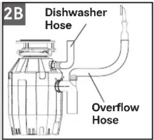
▶ Connect overflow hose (fig. 2B) using hose clamp. If hose size is different, you need a stepped rubber adaptor.
▶ Connect dishwasher hose (fig. 2B) using hose clamp. Make sure all plumbing connections are tight and in accordance with all plumbing codes and ordinances. Run water and check for leaks.
INSTALLATION OF MOUNTING ASSEMBLY
NOTE: The mounting components are assembled out of the box in the same order they will be assembled on the sink, so please pay close attention to the order of the mounting system components before you disassemble them.
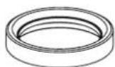
The cushion ring and the lower mounting ring will remain attached to the disposer during installation. Disassemble the other components of the mounting assembly by rotating lower mounting ring clockwise until the lower mounting ring tabs slide off from the upper mounting ring ramp. This will allow you to separate the upper assembly from the remaining lower mounting assembly.
▶ Unscrew the 3 mounting screws until the upper mounting ring can be moved to the top of the support flange. Remove the retainer ring with a screw driver.
▶ Keep the remaining parts placed together in the order they were removed. Before you connect the disposer to the mounting assembly under the sink, make sure the lower mounting ring is in place and the black cushion ring is still engaged properly to the top of the disposer opening. (Do not remove the cushion ring.)
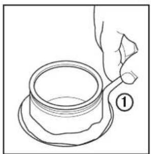
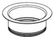
▶ Be sure the sink is clean. Install a bead of plumbers putty to the sink flange (1). From top of the sink, push the sink flange down against the sink opening to make a good seal (2). Do not move or rotate the sink flange once it has been seated or the seal may be broken.
natural_image
Line drawing of a hand holding a cup and saucer, with a numbered label (1) on the cup (no text or symbols on the cup itself)
natural_image
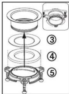
Diagram of a mechanical assembly with concentric rings and a downward arrow, no text or symbols presentPlace a heavy object, such as the disposer (use a towel to prevent sink scratching) on top of the sink flange to hold it down.
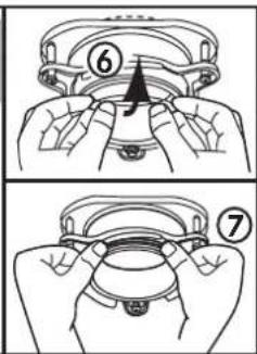
▶ Take the remaining portion of the mounting assembly, that was put aside. From under the sink insert the fibre gasket (3), then the support flange (4), and then the upper mounting ring (5).
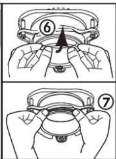
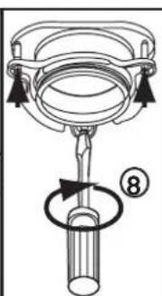
▶ Hold the three parts in place while attaching the retainer ring (6) by pulling it apart and sliding it onto the sink flange (7) until it snaps into the groove of the sink flange (7).
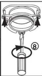
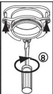
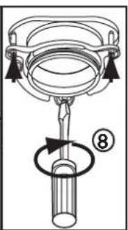
▶ Tighten the three mounting screws evenly and firmly against the supporting flange (8). Do not over tighten.
- Trim off any excess plumber's putty.
▶ Attach disposer onto the upper mounting ring by aligning the three mounting tabs on the lower mounting ring with the slide-up ramps on the upper mounting ring and rotating counter clockwise.
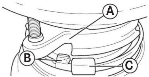
The lower mounting ring (which is part of the disposer) has 3 tabs that grab the mounting ring ramp.
(A) points to the upper mounting ring.
(B) is the tab that slides up onto the "Ramp".
(C) is the „Ear“ that is used to help rotate the lower mounting ring.
▶ Use a screwdriver for leverage if needed.
natural_image
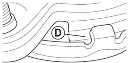
Diagram of a boat hull with a marked point D, showing hull lines and water flow (no text or symbols)▶ Lift and turn the lower mounting ring counter clockwise until all three mounting tabs lock over the ridges (F) on the slide-up ramps (D) of the upper mounting ring.
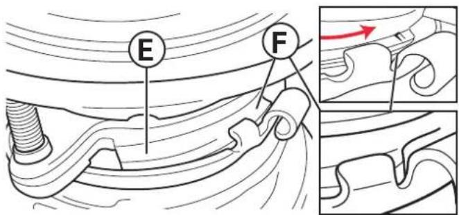
As the lower mounting ring is turned counter clockwise each tab slides up onto the upper mounting ring ramp (E) and locks in position over the ridges (F).
▶ Use a screwdriver or hammer for leverage if needed.
▶ If a disposer needs to be removed, tapping on the Ear clockwise with a hammer will easily loosen the lower mounting ring.
Electrical connection
▷ Connect disposer to appropriate household current only.
The receptacle to which this appliance is connected must be controlled by a switch.

WARNING: Improper connection of the equipment-earthing conductor can result in a risk of electric shock. Check with a qualified electrician or serviceman if you are in doubt as to whether the appliance is properly earthed. Do not modify the plug provided with the appliance if it will not fit the outlet. Have a proper outlet installed by a qualified electrician.
Earthing instructions
FOR WASTE DISPOSERS EQUIPPED WITH AN EARTHED PLUG-IN POWER CORD
This appliance must be earthed. In the event of a malfunction or breakdown, earthing provides a path of least resistance for electric current to reduce the risk of electric shock. This appliance is equipped with a cord having an equipment-grounding conductor and a grounding plug.
The plug must be plugged into an appropriate outlet that is properly installed and grounded in accordance with all local codes and ordinances.
▷ If the supply cord is damaged it must be replaced by the manufacturer, its service agent or similarly qualified person in order to avoid a hazard.
Removing an attached power cord or plug voids the warranty.
The following UK Electrical Section is for United Kingdom only - skip if not applicable.
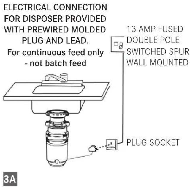
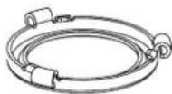
WHEN USING THE ATTACHED PRE-WIRED MOULDED PLUG AND LEAD (fig. 3A)
√ These disposers are engineered to be connected to a 220/240 V\~-50/60 Hz electrical supply through the attached three-pin plug and into a wired socket.
√ The disposer must be protected by a BS 1363 13 Amp fuse. The fuse is included within the molded plug and lead, attached to the disposer.
√ The 13 Amp double pole switched spur switch should be positioned higher than the sink countertop and at a minimum of one meter from the side of the sink, away from water splashes and out of the reach of children. This spur switch must be a double pole with at least 3 mm contact separation in each pole. 20 Amp DP switches BS 3676 meet this condition.
√ To avoid accidentally leaving the disposer running, a switch with a neon indicator lamp is suggested.
√ A 13 Amp ASTA approved fuse, to BS 1363 must be fitted in the fuse carrier of this spur switch.
ELECTRICAL CONNECTIONS:
▶ Simply insert the plug into the socket wired as previously described.
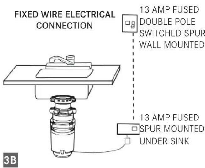
WHEN NOT USING THE PRE-WIRED PLUG BUT WIRING DIRECT WITH FIXED WIRING (fig. 3B).
√ The switches used must be double pole type and have at least a 3 mm contact separation in each pole (20 Amp DP switches to BS 3676 meet this requirement). Prepare the tips of the wires of the electrical lead and attach to the junction box.
√ Disconnect the junction box from the electrical supply before making the following connections:
√ The green and yellow wire must be connected to the terminal marked in one of the following ways:
- with the letter "E"
- by the earth symbol

- coloured green or green and yellow.
√ The brown wire must be connected to the terminal that is marked with the letter „L“.
√ The blue wire must be attached to the terminal that is marked with the letter „N“.
(NOTE: As your disposer has a molded plug on the lead and the plug is not to be used, cut it off and dispose of it wisely. A moulded plug with a loose lead with disconnected wires can be hazardous as an electrical shock hazard could occur should such a plug be inserted into a 13 Amp socket anywhere within the home.)
IS THE DISPOSER EARTHED?

WARNING: this appliance must be earthed! In the event of a malfunction of breakdown, Earthing reduces the risk of shock. This disposer must be connected to an earthed, metal, permanent wiring conductor and connected to the equipment earthing terminal or lead on the disposer.
Replacing the fuse in moulded plugs
√ The correct fuse cover must be refitted when changing the fuse.
√ Remove the fuse cover and slide the fuse out.
√ Replace it with a 13 Amp ASTA fuse (approved to BS 1363). Should the fuse cover be lost or damaged, an exact replacement should be used. These are available from an approved service agent, listed below. Never use the plug without the fuse cover fitted.
Attaching discharge elbow
MODELS CE-50, CE-75, TE-75S
Connect the waste elbow to the disposer by sliding the flange against the rubber gasket on the elbow and tightening the screws into the disposer (fig. 4A). Then connect bottom of the elbow by tightening the slip nut (fig. 4B). If using a straight pipe, it must have a lip similar to the one on the elbow. Remove the gasket from the elbow and install it on the straight pipe with the flat end of the gasket facing toward the disposer discharge opening.
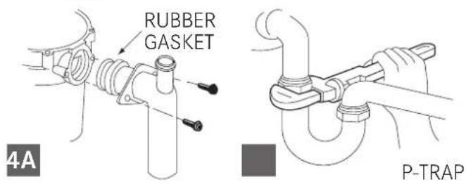
If you are connecting to a dishwasher, return to PLUMBING CONNECTION section (2A-B). If not, make sure all plumbing connections are tight and in accordance with all plumbing codes and ordinances. Run water and check for leaks.
MODELS TE-50, TE-75, TE-125, TE-125BF
▶ Depress the wings on the spring clamp to remove it from the rubber sleeve. Slip the spring clamp over the smooth side of the elbow and slide it towards the lipped side of the elbow (fig. 4C).
▶ Insert the waste elbow into the rubber sleeve so the elbow lip fits into the groove located inside the rubber sleeve. Position the spring clamp over the rubber sleeve and secure (fig. 4D). If using a straight pipe, use one with a lip matching the lip on the elbow supplied with the disposer.
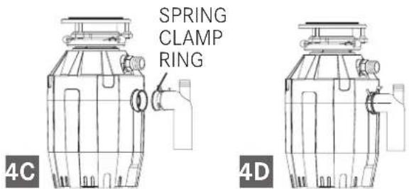
▶ If you are connecting to a dishwasher, return to PLUMBING CONNECTION section (2A-B). If not, make sure all plumbing connections are tight and in accordance with all plumbing codes and ordinances. Run water and check for leaks.
Air switch operated
Disposer Air Switch Assembly
The Actuator which consists of:
- Actuator Button
- Actuator Nut
- Actuator Outlet (Threaded portion)
THE AIR SWITCH SENSOR ENCLOSURE which is installed into the disposer. Only the air tube nozzle is visible from the outside of the disposer.
AIR TUBE ASSEMBLY which consists of:
- Air Tube-Clear or black
- Air Tube Nut
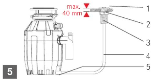
Installation and Operating Instructions
▶ If a hole does not already exist - drill a hole of 35 mm to 40 mm into the sink or countertop where the actuator button (1) is to be placed.
▶ Insert, from the top, the actuator outlet through the drilled hole.
Thread the actuator nut (2) onto the actuator outlet (3) and tighten firmly by hand.
▶ Firmly connect air tube: one side to actuator outlet (3) and one side to sensor inlet.
▶ Plug disposer power cord into main electrical service.
▶ To turn on disposer, press actuator button (1). To turn off, press actuator button again.
Suggestions
▶ Be sure disposer is empty before using your dishwasher so it may drain properly.
▶ You may want to leave the stopper in the sink drain when not in use to prevent utensils and foreign objects from falling into the disposer.
▶ Your disposer is sturdily built to give you many years of trouble free service. It will handle all normal food wastes, but it will NOT grind or dispose of such items as plastic, tin cans, bottle caps, glass, china, leather, cloth, rubber, string, clam and oyster shells, aluminum foil or feathers.
OPERATING INSTRUCTIONS
Your disposer is Continuous Feed if you did not specifically purchase a Batch Feed Disposer.
Continuous feed
The Anti-Jam Swivel Impellers make a clicking sound as they initially swing into place. This indicates normal operation.
▶ Remove sink stopper. Turn on a medium flow of cold water.
▶ Turn switch to ON position; your motor will be turning at full speed and ready to use.
▶ Scrape in food waste. Down the drain go table scraps, peelings, rinds, seeds, pits, small bones and coffee grounds. To speed up food waste disposal, cut or break up large bones, rinds and cobs.
▶ Large bones and fibrous husks require considerable grinding time and are more easily thrown away with other trash. Do not be alarmed that the disposer slows down while grinding. The disposer is actually increasing torque (grinding power) and is operating under normal conditions.
▶ Before turning disposer off, let water and disposer run for approximately 15 seconds after shredding stops. This assures that all waste is thoroughly flushed through trap and drain.
▶ It is not recommended to use hot water while running disposer. Cold water will keep waste and fats solid so disposer can flush away particles.
Batch feed
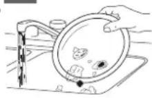
▶ Remove sink stopper. Turn on a medium flow of cold water.
▶ Scrape in food waste.
Down the drain go table scraps, vegetable peelings, cobs, rinds, pits, bones and coffee grounds (fig. 6A).
▶ Insert stopper to start disposer. (fig. 6B). One of the two small slots in stopper base must line up with switch plunger inside the neck of the disposer.
Push down firmly to turn the
6A
6B
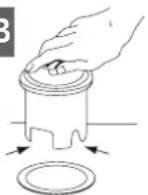
disposer on. Lift stopper to shut the disposer off.
▶ Run disposer for 15 seconds after shredding stops. This ensures that all waste is thoroughly flushed through the drain.
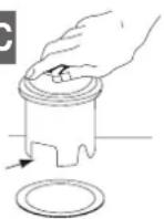
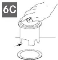
▶ To fill sink, insert stopper and align the largest slot with the switch plunger (fig. 6C). Push down to seal sink without starting the disposer. When medium sized slot (fig. 6B) in
stopper base is lined up with the switch plunger, water can drain, but tableware, etc., cannot be accidentally dropped into disposer.
6C

CAUTION
▷ Cold water recommended.
Do not use the food waste disposer with hard materials like glass or metal.
▷ Turn the machine off or unplug it while trying to unblock a blocked turntable with a wooden spoon.
DO NOT PUT INSIDE :
- Caustic Soda and drain cleaning chemicals (Hydrochloric and muriatic acid), as they cause serious corrosion of metal parts. If used, resulting damage can be easily detected and all warranties are void
- Fat and oil in excess
- Plastic materials
- Pumpkins
- Banana skin
- Leaves of pineapple
- Asparagus
- Artichokes
- Shell (es. oyster, mussel, ecc.)
- Medicine
- Metal (bottle top)
- Plastic pieces
- Cow bone a/o large bones
TO BE PUT INSIDE:
- Corn cobs
– Little bones (es. chicken and rabbit bones) - Nut shells
- Meat scraps
- Melon and watermelon skins
- Fruit pips
- Grape pips
- Rice
- Grounds of coffee
- Eggshells
- Fishbones
- Fish heads
- Pasta
- Vegetables or vegetable peel
- Cheese
- Bread
- Soup
TROUBLESHOOTING
Before seeking repair or replacement, we recommend that you review the following:
LOUD NOISES (other than those during grinding of small bones and fruit pips): these are usually caused by accidental entry of a spoon, bottle cap or other foreign object.
▶ To correct this, turn off electrical switch and water. After disposer has stopped.
UNIT DOES NOT START:
▶ Unplug power cord or turn either the wall switch or breaker box switch to “OFF” position, depending on your model and wiring configuration.
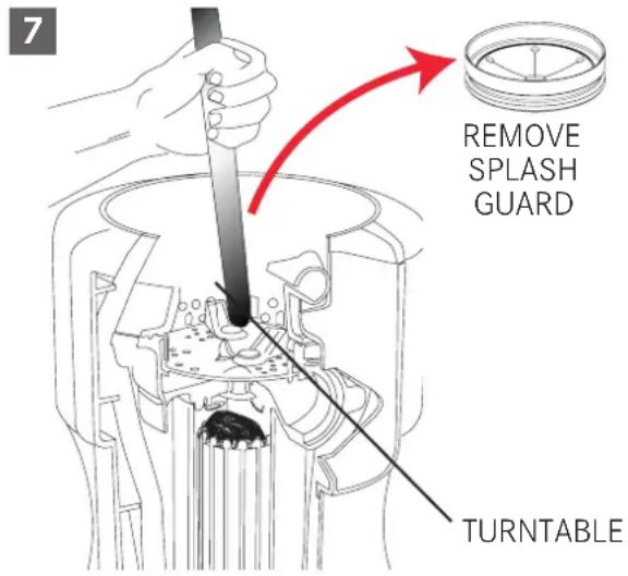
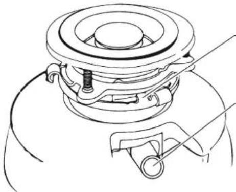
Remove stopper and /or splash guard. Check to see if turntable will rotate freely using a wooden broom handle. If turntable rotates freely, replace splash guard and check reset button to see if it has been tripped. Reset button is red and located opposite discharge elbow, near the bottom (fig. 3). Push button in until it clicks and remains depressed.
If reset button has not been tripped, check for shorted or broken wire connecting to disposer. Check electrical power switch, fuse box or circuit breaker. If wiring and electrical components are intact, the unit may have internal problems that require service or replacement.
IF TURNTABLE DOES NOT ROTATE FREELY:
▶ Turn off disposer, then check for any foreign object lodged between the turntable and grind ring. Dislodge object by rotating table with a wooden broom handle and remove object (fig. 7). If no foreign object is present, there may be internal problems.
LEAKS: If the unit leaks at the top, it may be due to:
■ Improper seating of sink flange (gasket centering, putty or tightening).
■ Support ring not tightened properly.
■ Defective or improperly installed cushion mount.
If unit leaks at the waste elbow, leak may be due to improper tightening of elbow flange screws.
CLEANING AND MAINTENANCE
DO NOT ATTEMPT TO LUBRICATE YOUR DISPOSER!
The motor is permanently lubricated. The disposer is self cleaning and scours its internal parts with each use. Never put caustic soda or chemical drain cleaners, as hydrochloric and muriatic acid, products for unclogging the sink drain, into the disposer, as they cause serious corrosion of metal parts.
If used, resulting damage can be easily detected and all warranties are void. Mineral deposits from your water can form on the stainless steel turntable, giving the appearance of rust. Do not be alarmed, the stainless steel turntables used will not corrode.
DISPOSAL
The symbol on the product or on the packaging indicates that the device must not be disposed of in the domestic waste.
By disposing of the device in a proper way you help to avoid harmful consequences to environment and health.
Further information about recycling the device is available from the competent authority, the local refuse disposal service or the vendor of the device.
▷ Dispose of the device, which is to be discarded, via a specialised waste collection point for electronic and electrical devices.
In accordance with the article of Legislative Decree no. 15 dated 25 July, Implementation of Directive 2002/96/EC regarding the reduction of the hazardous substances used in in electrical and electronic appliances, and waste disposal". The barred dustbin symbol on the appliance indicates that at the end of its working life the product must not be disposed of as household waste.
Consequently, when the appliance has reached the end of its working life the user must take it to a suitable recycling centre for electronic and electrotechnical waste, or return it to the dealer when purchasing a new appliance of equivalent type.
Proper separate waste collection of the scrapped appliance for subsequent recycling, treatment and environmentally-friendly disposal helps prevent a potentially negative impact on the environment and health and facilitates recycling of the materials used in appliance construction.
The food waste disposer is for domestic use only.
INHALTSVERZEICHNIS
natural_image
Technical line drawing of a mechanical component with no visible text or symbolsMONTAGELASCHE
GESCHIRRSPÜLER-EINLASS
natural_image
Illustration of a hand using a tool to tie a U-shaped pipe knot (no text or symbols)
natural_image
Illustration of a hand using a tool to lift a cylindrical object (no text or symbols present)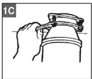
natural_image
Line drawing of a hand adjusting a mechanical component (no text or symbols)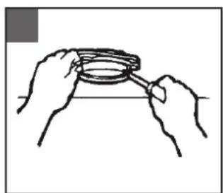
natural_image
Line drawing of two hands holding a circular object with a ring, no text or symbols presentnatural_image
Line drawing of a hand holding a cup and saucer, with a numbered label (1) pointing to the cup (no text or symbols on the cup itself)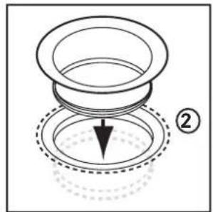
natural_image
Diagram of a mechanical component with a downward arrow and dotted base, labeled with number ② (no text or symbols on the diagram itself)natural_image
Diagram of fluid flow around a pipe with a labeled component (D), showing streamlines and flow direction (no text or symbols beyond label)natural_image
Illustration of hands holding a magnifying glass over a surface, with no visible text or symbols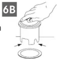
PARE-ÉCLABOUSSURES AMOVIBLE
BRIDE DE L'ÉVIER
JOINT FIBRE
BRIDE DE SOUTIEN
ANNEAU DE MONTAGE SUPÉRIEUR
VIS DE MONTAGE
ANNEAU DE RETENUE
COUSSIN*
ANNEAU DE MONTAGE INFÉRIEUR*
natural_image
Technical line drawing of a mechanical component with no visible text or symbolsERGOT DE MONTAGE
RACCORD DU LAVE-VAISSELLE
natural_image
Illustration of a hand using a tool to tie a U-shaped pipe knot (no text or symbols)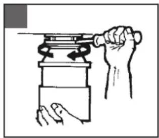
natural_image
Illustration of hands using a tool to lift a cylindrical object (no text or symbols present)
natural_image
Line drawing of a hand holding a mechanical component (no text or symbols)
natural_image
Line drawing of two hands holding a magnifying glass (no text or symbols)RACCORDEMENT DE PLOMBERIE
natural_image
Diagram of a mechanical or fluid system with wavy lines and a labeled component 'D' (no text or symbols beyond the label)Alimentation continue
Alimentation discontinue
natural_image
Technical line drawing of a mechanical component with no visible text or symbolsLINGUETTA DI FISSAGGIO
ENTRATA DELLA LAVASTOVIGLIE
natural_image
Illustration of a hand using a tool to tie a U-shaped pipe knot (no text or symbols)
natural_image
Illustration of a hand using a tool to lift a cylindrical object (no text or symbols present)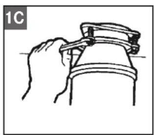
natural_image
Line drawing of a hand gripping a mechanical component (no text or symbols)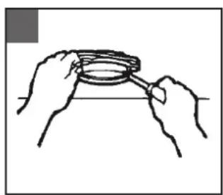
natural_image
Line drawing of two hands holding a circular object with a ring, no text or symbols presentnatural_image
Line drawing of a hand holding a cup and saucer, with a numbered label (1) on the cup (no text or symbols on the cup itself)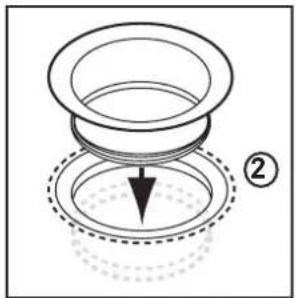
natural_image
Diagram of a mechanical assembly with a cylindrical component and a dashed circular base, no text or symbols present.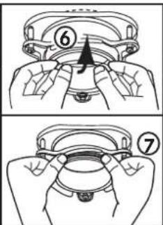
natural_image
Topographic map section showing contour lines and a marked location (D), no text or labels present.natural_image
Illustration of a hand using a tool to tie a pipe with a handle (no text or symbols)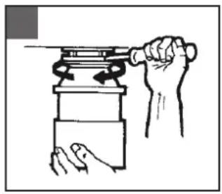
natural_image
Illustration of hands using a tool to lift a mechanical component (no text or symbols present)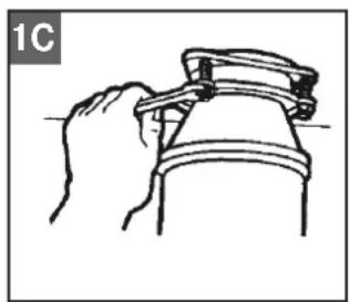
natural_image
Line drawing of a hand gripping a mechanical component (no text or symbols)
natural_image
Line drawing of two hands holding a circular object with a ring, no text or symbols presentnatural_image
Line drawing of a hand holding a cup and a leaf, with number 1 label (no text or symbols on the diagram itself)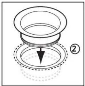
natural_image
Diagram of a mechanical assembly with concentric rings and a downward arrow, no text or symbols present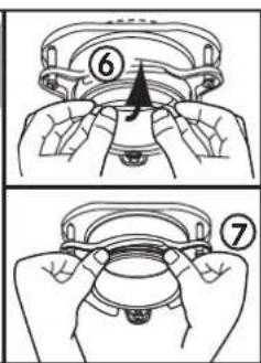
natural_image
Diagram of a mechanical or fluid system with wavy lines and a labeled component (D), no readable text or symbols present.natural_image
Illustration of a hand using a tool to tie a U-shaped pipe knot (no text or symbols)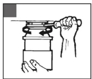
natural_image
Illustration of a hand using a tool to lift a cylindrical object (no text or symbols present)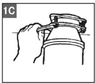
natural_image
Line drawing of a hand gripping a mechanical component (no text or symbols)
natural_image
Line drawing of two hands holding a circular object with a ring, no text or symbols presentnatural_image
Line drawing of a hand holding a cup and a small object, no text or symbols present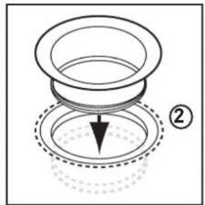
natural_image
Diagram of a mechanical component with a downward arrow and dotted base, no text or symbols present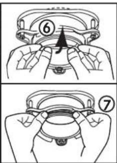
natural_image
Diagram of fluid flow around a pipe with a labeled component (D), showing streamlines and flow patterns without any text or symbols.natural_image
Technical line drawing of a mechanical component with no visible text or symbolsnatural_image
Illustration of a hand using a tool to tie a U-shaped pipe knot (no text or symbols)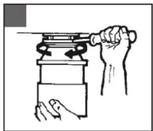
natural_image
Illustration of a hand using a tool to lift a cylindrical object (no text or symbols present)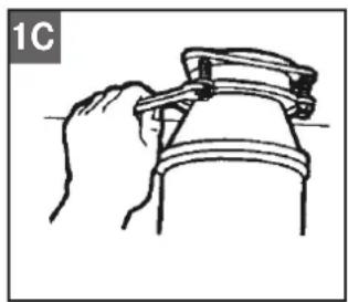
natural_image
Line drawing of a hand holding a mechanical component (no text or symbols)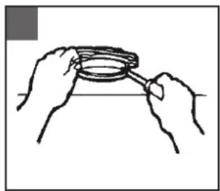
natural_image
Line drawing of two hands holding a circular object with a ring, no text or symbols presentΥΔΡΑΥΛΙΚΗ ΣΥΝΔΕΣΗ
natural_image
Line drawing of a hand holding a cup and saucer, with a numbered label (1) pointing to the cup (no text or symbols on the cup itself)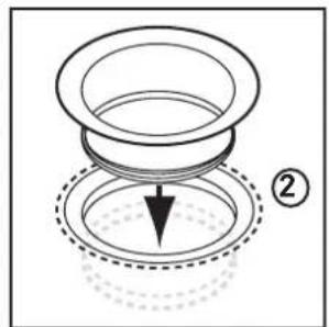
natural_image
Diagram of a mechanical component with a downward arrow and dotted base, labeled with number ② (no text or symbols on the diagram itself)natural_image
Diagram of a boat hull with a marked point D, showing hull lines and water flow (no text or symbols)natural_image
Technical line drawing of a mechanical device with no visible text or symbolsnatural_image
Technical line drawing of a mechanical component with no visible text or symbolsZACZEP MOCUJACY
WLOT ZE ZMYWARKI
natural_image
Illustration of a hand connecting a pipe with a clamp (no text or symbols)
natural_image
Illustration of hands using a tool to lift a cylindrical object (no text or symbols present)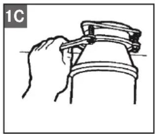
natural_image
Line drawing of a hand holding a mechanical component (no text or symbols)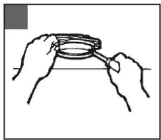
natural_image
Line drawing of two hands holding a circular object with a handle, no text or symbols presentPODŁĄCZANIE DO SIECI KANALIZACYJNEJ
natural_image
Diagram of a boat hull with a marked point D, showing hull lines and water flow (no text or symbols)MODELE CE-50, CE-75, TE-75S
natural_image
Technical line drawing of a mechanical component with no visible text or symbolsURECHE DE MONTAJ
RACORD INTRARE MAŞINA DE SPĂLAT VASE
natural_image
Illustration of a hand using a tool to tie a U-shaped pipe knot (no text or symbols)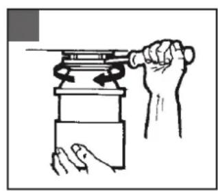
natural_image
Illustration of a hand using a tool to lift a cylindrical object (no text or symbols present)
natural_image
Line drawing of a hand gripping a mechanical component (no text or symbols)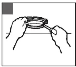
natural_image
Line drawing of two hands holding a circular object with a handle, no text or symbols presentRACORDAREA TEVĂRIEI
natural_image
Line drawing of a hand holding a cup and a leaf, with no text or symbols present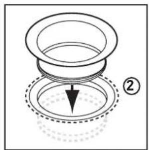
natural_image
Diagram of a mechanical assembly with concentric rings and a downward arrow, no text or symbols present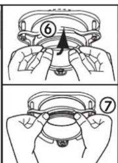
natural_image
Diagram of a boat hull with a marked point D, showing hull lines and water flow (no text or symbols)MODELELE CE-50, CE-75, TE-75S
natural_image
Technical line drawing of a mechanical component with no visible text or symbolsКРЕПЕЖНАЯ ЗАЩЕЛКА
natural_image
Illustration of a hand using a tool to adjust a U-shaped pipe fitting (no text or symbols present)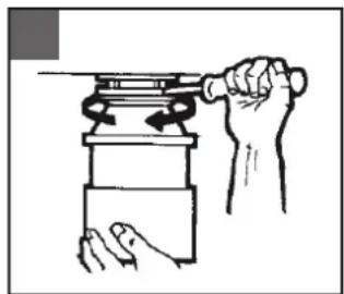
natural_image
Illustration of a hand using a tool to lift a cylindrical object (no text or symbols present)
natural_image
Line drawing of a hand gripping a mechanical component (no text or symbols)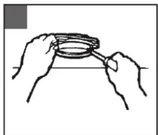
natural_image
Line drawing of two hands holding a circular object with a ring, no text or symbols presentМОНТАЖ САНТЕХНИКИ
natural_image
Line drawing of a hand holding a cup and saucer, with a numbered label (1) pointing to the cup (no text or symbols on the cup itself)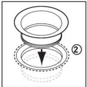
natural_image
Diagram of a mechanical component with a downward arrow and dotted outline, no text or symbols present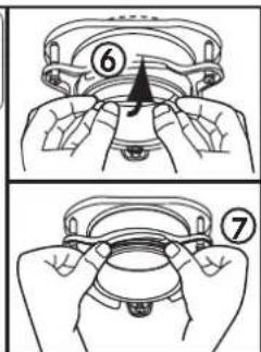
natural_image
Diagram of a mechanical or fluid system with curved flow lines and a labeled component 'D' (no text or symbols beyond the label)natural_image
Diagram showing fluid flow patterns with a red arrow indicating direction, no text or symbols presentnatural_image
Illustration of a hand using a tool to tie a U-shaped pipe knot (no text or symbols)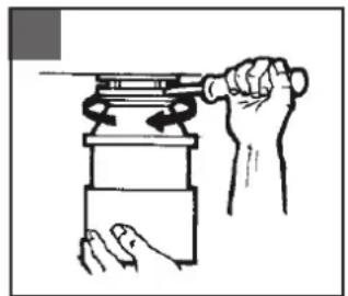
natural_image
Illustration of a hand using a tool to lift a cylindrical object (no text or symbols present)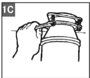
natural_image
Line drawing of a hand gripping a mechanical component (no text or symbols)
natural_image
Line drawing of two hands holding a magnifying glass over a surface (no text or symbols)TESISAT BAĞLANTISI
natural_image
Line drawing of a cup and saucer with a hand holding a leaf, no text or symbols present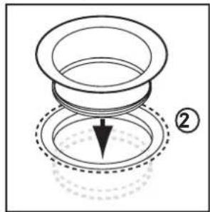
natural_image
Diagram of a mechanical component with a downward arrow and dotted base, no text or symbols presentnatural_image
Abstract line drawing of wave-like patterns with no text or symbolsnatural_image
Line drawing of a hand using a wrench to adjust a pipe fitting (no text or symbols)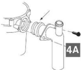
natural_image
Mechanical assembly diagram showing a pipe fitting with a valve and labeled section 4A (no text or symbols beyond label)natural_image
Technical line drawing of a mechanical device with no visible text or symbols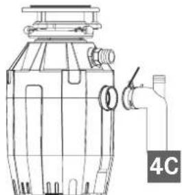
natural_image
Technical line drawing of a mechanical device with pipe and valve (no text or symbols)natural_image
Technical line drawing of a mechanical component with a base and central housing (no text or symbols)3B
natural_image
Abstract line drawing with wavy lines and a circular symbol labeled 'D' (no text or symbols present)natural_image
Illustration of hands using a mechanical device to lift a cylindrical component (no text or symbols)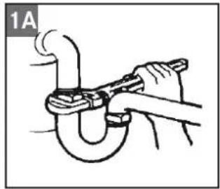
natural_image
Illustration of a hand using a tool to adjust a pipe fitting (no text or symbols present)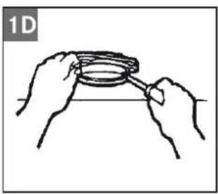
natural_image
Line drawing of two hands holding a coiled spring (no text or symbols)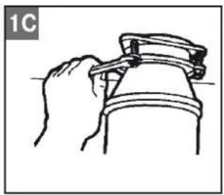
natural_image
Line drawing of a hand holding a mechanical component (no text or symbols)Franke Kindred Canada Limited
Midland, ON L4R 4K9
Phone +1 705 526 5427
Czech Republic
Franke s.r.o.
190 00 Praha 9
Phone +420 281 090 411
Denmark
Franke Kitchen Systems Denmark
8520 Lystrup
Phone +45 8624 9024
Egypt
Franke Kitchen Systems Egypt S.A.E.
6th of October City
Phone +202 3828 0000
Finland
Franke Finland Oy
76850 Naarajärvi
Phone +358 15 341 11
France
Franke France S.A.S.
60230 Chambly
Phone +33 130 289 400
Germany
Franke GmbH
79713 Bad Säckingen
Phone +49 7761 52 0
Greece
Franke Hellas S.A.
19003 Markopoulo Attikis (Athens)
Phone +30 22991 500 00
Hong Kong SAR
Franke Asia Hong Kong Office
Causeway Bay
Phone +852 3184 1900
India
Franke Faber India Limited
Aurangabad - 431 136
Phone +91 240 2556697/98
Italy
Franke S.p.A.
37019 Peschiera del Garda
Phone +39 045 644 9311
Kazakhstan
Franke Kazakhstan Ltd.
040918 Almaty City
Phone +7 727 297 3812
Morocco
Franke Kitchen System SARL
21 000 Casablanca
Phone +212 522 674 200
Norway
Franke Kitchen Systems Norway
8520 Lystrup, Denmark
Phone +47 35 566 450
P.R. China
Franke (China) Kitchen Systems Co., Ltd.
Heshan, Guangdong, 529700
Phone +86 750 841 9288
Shanghai office +86 215 150 6715
Poland
Franke Polska Sp. z o.o.
05-090 Raszyn
Phone +48 22 711 6700
Portugal
Franke Portugal S.A.
2735-531 Cacém
Phone +351 21 426 9670
Romania
Franke Romania SRL
Pantelimon 077145
Phone +40 21 350 1550
Russia
Franke Russia GmbH
199106 St. Petersburg
Phone +7 812 703 1503
Singapore
Franke Singapore Pte. Ltd.
068811 Singapore
Phone +65 6709 5608
Slovak Republic
Franke Slovakia s.r.o.
010 01 Žilina
Phone +421 41 733 6200
South Africa
Franke Kitchen Systems (Pty.) Ltd.
Durban 4052
Phone +27 31 450 6300
Spain
Franke Kitchen Systems Sweden
168 67 Bromma
Phone +46 912 405 00
Switzerland
Franke Consumer Products Inc.
Smyrna, TN 37167
Phone +1 615 462 4000