
EHSH04P30D3 - Air-conditioner DAIKIN - Free user manual and instructions
Find the device manual for free EHSH04P30D3 DAIKIN in PDF.

| Product type | Daikin Altherma 3 R ECH₂O heat pump / air conditioner |
| Model | EHSH04P30D3 |
| Power supply | 230 V ~ 50 Hz (single-phase); optional 400 V three-phase for Backup-Heater |
| Max. power input | Variable according to configuration; Backup-Heater up to 9 kW |
| Main functions | Heating, cooling (depending on model), domestic hot water (DHW) production, electric backup, compatible with solar, Smart Grid |
| Refrigerant | R32 (flammable) |
| Max. operating pressure (heating) | 3 bar (30 m CE) |
| Max. operating pressure DHW | 10 bar |
| DHW tank volume | 270 L (approx., depending on configuration) |
| DHW temperature range | 35 °C to 65 °C (max 80 °C with anti-legionella protection) |
| Heating flow temperature range | 20 °C to 65 °C (depending on mode) |
| Outdoor sensor type | NTC (optional) |
| Protection type | IP X4 (depending on model) |
| Tank material | Polypropylene with PUR foam insulation |
| DHW heat exchanger | Stainless steel (plate) |
| Integrated expansion vessel | No, must be installed on site (capacity according to installation) |
| Maintenance and cleaning | Regular air purging, pressure check, filter cleaning, annual maintenance by qualified professional |
| Safety | Mandatory RCD, anti-scald protection, 10 bar safety valve, safety shutdown in case of water shortage |
| Hydraulic connections | Heating flow/return 1", cold/hot water G 1/2", solar flow/return G 3/4" |
| Refrigerant connections | Liquid 6.35 mm (1/4"); Gas 15.9 mm (5/8") |
| Max. ambient temperature of room | 40 °C |
| Minimum distance to heat sources | 1 m (walls >80 °C) |
| Recommended minimum room height | 1200 mm above the unit |
| Warranty | Subject to legal conditions; annual maintenance required for validity |
Frequently Asked Questions - EHSH04P30D3 DAIKIN
User questions about EHSH04P30D3 DAIKIN
0 question about this device. Answer the ones you know or ask your own.
Ask a new question about this device
Download the instructions for your Air-conditioner in PDF format for free! Find your manual EHSH04P30D3 - DAIKIN and take your electronic device back in hand. On this page are published all the documents necessary for the use of your device. EHSH04P30D3 by DAIKIN.
USER MANUAL EHSH04P30D3 DAIKIN
Installation and operating manual
Daikin Altherma 3 R ECH₂O

natural_image
White and black rectangular electronic device with a digital display (no visible text or symbols)EHSX(B)04P30D3
EHSX(B)04P50D3
EHSH(B)04P30D3
EHSX(B)08P30D3
EHSX(B)08P50D3
EHSH(B)08P30D3
EHSH(B)08P50D3
Installation and operating manual Daikin Altherma 3 R ECH₂O
1 General safety precautions 3
1.1 Particular safety instructions .... 3
1.1.1 Observing the instructions 3
1.1.2 Meaning of warnings and symbols.... 4
1.2 Safety instructions for installation and operation.... 5
1.2.1 General 5
1.2.2 Intended use 5
1.2.3 Installation room....6
1.2.4 Electrical installation 6
1.2.5 Requirements for heating and storage water...... 6
1.2.6 Heating system and sanitary connection 7
1.2.7 Operation 7
1.3 Maintenance, troubleshooting and decommissioning 7
1.4 Warranty conditions....7
2 Product description 8
2.1 Design and components......8
2.2 Function of the 3-way changeover valves .... 10
3 Set-up and installation 11
3.1 Dimensions and connection dimensions ..... 11
3.2 Transport and delivery.... 12
3.3 Installing the heat pump 12
3.3.1 Selecting the installation site.... 12
3.3.2 Installing the device 13
3.4 Preparing the device for installation 13
3.4.1 Remove the front screen.... 13
3.4.2 Remove the protective cover 14
3.4.3 Moving the switch box to the service position.... 14
3.4.4 Open the switch box 14
3.4.5 Removing the bottom thermal insulation.... 15
3.4.6 Opening the air purge valve.... 15
3.4.7 Aligning the connections of the heating inflow and return flow 16
3.4.8 Making the hood opening.... 17
3.4.9 Installing the rotary switch of the controller.... 17
3.4.10 Securing the hood.... 1
3.5 Installing optional accessories.... 18
3.5.1 Installation of electric backup heater (EKBUxx).... 18
3.5.2 Installation of the external heat generator connection set (EKBUHSWB) 18
3.5.3 Installation of the DB connection kit.... 18
3.5.4 Installation of the P connection kit 18
3.6 Water connection 19
3.6.1 Minimum water volume.... 19
3.6.2 Connecting hydraulic lines.... 19
3.6.3 Connecting the drain.... 20
3.7 Electrical connection 20
3.7.1 Overall connection diagram 22
3.7.2 Position of the PCBs and terminal strips.... 23
3.7.3 Mains connection.... 23
3.7.4 General information on the electrical connection..... 23
3.7.5 Connecting the heat pump outdoor unit.... 23
3.7.6 Connecting the outdoor temperature sensor (optional) 24
3.7.7 External switching contact 24
3.7.8 EBA (external requirement request) 24
3.7.9 Connecting an external heat generator.... 25
3.7.10 Connecting the room thermostat.... 26
3.7.11 Connection of optional RoCon system components ... 26
3.7.12 Connecting the HP convector 26
3.7.13 Connecting switching contacts (AUX outputs) ...... 27
3.7.14 Low rate mains connection (HT/NT) 27
3.7.15 Connecting an intelligent controller (Smart Grid - SG) 28
3.8 Connection for refrigerant 28
3.8.1 Laying refrigerant piping 28
3.8.2 Pressure test and filling the refrigerant circuit.... 28
3.9 Filling the system.... 29
3.9.1 Checking the water quality and adjusting the manometer.... 29
3.9.2 Filling hot water heat exchangers 29
3.9.3 Filling the storage tank.... 29
3.9.4 Filling the heating system 29
4 Configuration 30
5 Check list for start-up 31
5.1 Requirements 31
5.2 Commissioning at low ambient temperatures 31
5.3 Bleeding the hydraulic system.... 31
5.4 Checking the minimum flow 32
5.5 Start screed drying (only if required) 32
5.6 Commissioning checklist 32
5.7 Handover to the operating company 33
6 Technical data 33
6.1 Information on the type plate.... 33
6.2 Characteristic lines 33
6.2.1 Sensor characteristic lines.... 33
6.2.2 Characteristic curves for pumps 34
6.3 Tightening torques.... 34
6.4 Minimum floor area and ventilation openings.... 34
6.5 Electrical connection diagram 36
6.6 Piping diagram for refrigerant circuit 38
1 General safety precautions
1.1 Particular safety instructions

WARNING
Devices that have not been set up and installed correctly can impair the function of the device and/or cause serious or fatal injury to the user.
- Work on the indoor unit (such as setup, servicing, connection and initial commissioning) must only be carried out by persons who are authorised and who have successfully completed qualifying technical or vocational training, and who have taken part in advanced training sessions recognised by the relevant responsible authorities for the specific activity. These include, in particular, certified heating engineers, qualified electricians and HVAC specialists who, because of their professional training and expert knowledge, have experience in the professional installation and maintenance of heating, cooling and air conditioning systems as well as hot water storage tanks.

WARNING
Disregarding the following safety instructions may result in serious physical injury or death.
- This device may only be used by children aged 8 and above and by persons with restricted physical, sensory or mental capabilities or with a lack of experience and knowledge if they are under supervision or if they have been instructed in the safe use of the equipment and understand the dangers arising from it. Children must not play with the device. Cleaning and user maintenance must not be carried out by children without supervision.
- Establish the power supply in accordance with IEC 60335-1, via a separate isolator that separates all poles with a contact opening distance and that provides full disconnection in accordance with overvoltage category III.
- All electrical work must only be carried out by electrically qualified experts and with consideration of the local and national regulations and the instructions in this manual. Ensure that a suitable electrical circuit is used. Insufficient load capacity of the electrical circuit or improperly executed connections can result in electric shock or fire.
- The customer must install a pressure relief device with a rated over-pressure of less than 1.0 MPa (10 bar). The connected drain line must have a continuous gradient and a free outlet in a frost-free environment (see "3.3 Installing the heat pump" [▶ 12]).
- Water may drip out of the drain line of the pressure relief device. The drain opening must be left open to the atmosphere.
- The pressure relief device must be operated regularly in order to remove scale deposits and to make sure it is not blocked.
- The storage tank and hot water circuit can be drained. The instructions in "Temporary decommissioning" in the reference manual for the fitter must be complied with.
1.1.1 Observing the instructions
- The original documentation is written in German. All other languages are translations.
- Please read this manual carefully and thoroughly before proceeding with the installation or modification of the heating system.
1 General safety precautions
- The precautionary measures described in this document cover very important topics. Follow them meticulously.
- The installation of the system, and all activities described in this manual and the applicable documents for the installer must be carried out by an approved installer.
Documentation set
This document is part of a documentation set of other applicable documents. The complete set comprises:
- Installation manual for the indoor unit (format: paper – included in the indoor unit scope of delivery)
- Operating manual for the indoor unit (format: paper – included in the indoor unit scope of delivery)
- Operating manual for the heat pump (format: paper – included in the indoor unit scope of delivery)
- Installation manual for the outdoor unit (format: paper – included in the outdoor unit scope of delivery)
- Installation instructions for optional components (format: paper – included in the scope of delivery of the respective component)
- Installer reference guide of the indoor unit (format: digital)
- Installer reference guide of the outdoor unit (format: digital)
The reference guides contain the complete set of technical data, a detailed description of best practices and information on maintenance, troubleshooting and decommissioning.
The digital documents and the latest editions of the supplied documentation are available on the regional Daikin website or, on request, from your dealer. The Daikin website is easy to access using the QR code on your device.
1.1.2 Meaning of warnings and symbols
Warnings in this manual are classified according into their severity and probability of occurrence.
| DANGERIndicates an immediate danger.Disregarding this warning can lead to serious injury or death. |
| WARNINGIndicates a potentially dangerous situation.Disregarding this warning may result in serious physical injury or death. |
| CAUTIONIndicates a situation which may cause possible damage.Disregarding this warning can cause damage to property and the environment and result in minor injuries. |
| This symbol identifies user tips and particularly useful information, but not warnings or hazards |
Special warning signs
Some types of danger are represented by special symbols.
| Electric current | |
| Danger of explosion | |
| Risk of burns or scalds | |
| Risk of poisoning |
Validity
Some information in this manual has limited validity. The validity is highlighted by a symbol.
| Heat pump outdoor unit |
| Heat pump indoor unit |
Observe the specified tightening torque
p=0 Only applies to devices with unpressurised solar system connection (DrainBack).
Only applies to devices with a bivalent solar system connection (Biv).
Only applies to indoor units with cooling function
Handling instructions
1 Handling instructions are shown as a list. Actions where the sequential order must be adhered to are numbered.
1.2 Safety instructions for installation and operation
1.2.1 General

WARNING
Devices that have not been set up and installed correctly can impair the function of the device and/or cause serious or fatal injury to the user.
- Work on the indoor unit (such as setup, servicing, connection and initial commissioning) must only be carried out by persons who are authorised and who have successfully completed qualifying technical or vocational training, and who have taken part in advanced training sessions recognised by the relevant responsible authorities for the specific activity. These include, in particular, certified heating engineers, qualified electricians and HVAC specialists who, because of their professional training and expert knowledge, have experience in the professional installation and maintenance of heating, cooling and air conditioning systems as well as hot water storage tanks.
- Switch off the external main switch before starting any work on the indoor unit and secure against being switched on inadvertently.
- Do not leave any tools or other objects below the hood of the device after finishing installation or maintenance work.
Avoid danger
The indoor unit conforms to the state of the art and meets all recognised technical requirements. However, improper use can lead to serious injuries or death, as well as causing material damage. To prevent such risks, only install and operate the devices:
- as stipulated and in perfect condition,
- with an awareness of the safety and hazards involved.
This assumes knowledge and use of the contents of this manual, the relevant accident prevention regulations and the recognised safety-related and occupational medical rules.
Before working on the hydraulic system
- Work on the system (such as set-up, connection and initial commissioning, for example) must only be carried out by persons who are authorised, who have successfully completed qualifying
technical or vocational training for the respective activity and who have taken part in advanced training sessions recognised by the relevant responsible authority.
- When carrying out any work on the system, switch off the main switch and secure against being switched on inadvertently.
- Seals must not be damaged or removed.
- Make sure that the safety valves comply with the requirements of EN 12828 when connecting on the heating side and with the requirements of EN 12897 when connecting on the domestic water side.
1.2.2 Intended use
The indoor unit may only be used for domestic hot water preparation, as a room heating system and, depending on its design, as a room cooling system.
The indoor unit must only be installed, connected and operated according to the indications in these instructions.
Only the use of a suitable outdoor unit approved by the manufacturer is permitted.
1–1 Permissible combinations
| EHSX04P30DA3EHSX04P50DA3EHSXB04P30DA3EHSXB04P50DA3EHSH04P30DA3EHSHB04P30DA3 | |||
| EHSX08P30DA3EHSX08P50DA3EHSXB08P30DA3EHSXB08P50DA3EHSH08P30DA3EHSHB08P30DA3EHSHB08P50DA3 | |||
 | ERGA04DAV3ERGA04EAV3 | √ | × |
| ERGA06DAV3ERGA06EAV3 | × | √ | |
| ERGA08DAV3ERGA08EAV3 | × | √ | |
| ERGA04DAV3AERGA04EAV3A | √ | × | |
| ERGA06DAV3AERGA06EAV3A | × | √ | |
| ERGA08DAV3AERGA08EAV3A | × | √ | |
| ERGA04DAV37ERGA04EAV37 | √ | × | |
Any other use or use beyond the intended use is considered improper use. The operator alone bears responsibility for any resulting damage.
Intended use also includes compliance with the maintenance and service conditions. Spare parts must at least satisfy the technical requirements defined by the manufacturer. This is the case, for example, with original spare parts.
1.2.3 Installation room

WARNING
The plastic wall of the storage tank on the indoor unit can melt under the effects of external heat ( >80^ ) and, in the extreme case, can catch fire.
- Only install the indoor unit at a minimum clearance of 1 m from other heat sources (>80°C) (e.g. electrical heater, oil heater, chimney) and combustible materials.

CAUTION
- Only install the indoor unit if sufficient load-carrying capacity of the ground of 1050kg / m^2 plus safety margin is ensured. The ground must be flat, horizontal and level.
- Outdoor set up is not permissible.
- Set-up in an explosion-risk environment is not permissible.
- The electronic control system must not be exposed to weather effects such as rain and snow under any circumstances.
- The storage tank may not be exposed to continuous direct sunlight, as the UV radiation and the effects of the weather will damage the plastic.
- The indoor unit must be installed protected from frost.
-
Make sure that the supply company does not provide corrosive domestic water. Suitable water treatment may be required.
-
Always ensure the minimum distances from walls and other objects ("3.1 Dimensions and connection dimensions" [▶ 11]).
- Observe the special installation requirements of the R32 refrigerant (see "3.3.1 Selecting the installation site" [▶ 12]).

CAUTION
- If a DrainBack solar heating system is connected: Install the indoor unit far enough under the solar panels to allow complete emptying of the solar heating system. (Follow the instructions in the DrainBack solar heating system manual.) An insufficient height difference may lead to destruction of the DrainBack solar heating system.
- The indoor unit must not be operated in rooms with ambient temperatures of more than 40°C.
1.2.4 Electrical installation
- Electrical installations may only be carried out by electrical technicians and in compliance with valid electrical guidelines as well as the specifications of the responsible energy supply company.
- Compare the mains voltage indicated on the nameplate with the supply voltage before connecting to the mains.
- Before beginning work on live parts, disconnect them from the power supply (switch off main switch, remove fuse) and secure against unintentional restart.
- Device covers and service panels must be replaced as soon as the work is completed.
1.2.5 Requirements for heating and storage water
Damage due to deposits and corrosion: observe the relevant technical rules to avoid corrosion products and deposits.
Minimum requirements regarding the quality of filling and top-up water:
- Water hardness (calcium and magnesium, calculated as calcium carbonate): ≤3 mmol/l
- Conductivity: ≤1500 (ideal ≤100) μS/cm
- Chloride: ≤250 mg/l
- Sulphate: ≤250 mg/l
- pH value: 6.5 – 8.5
Measures for desalination, softening or hardness stabilisation are necessary if the filling and top-up water have a high total hardness (>3 mmol/l – total of the calcium and magnesium concentrations, calculated as calcium carbonate). We recommend the use of Fernox KSK limescale and corrosion protector. For other properties deviating from the minimum requirements, suitable conditioning measures are necessary to maintain the required water quality.
Using filling water and top-up water which does not meet the stated quality requirements can cause a considerably reduced service life of the equipment. The responsibility for this lies solely with the operator.

INFORMATION
If an optional external heat generator is connected, these minimum requirements also apply to the filling and supplementary water for this heating circuit.
1.2.6 Heating system and sanitary connection
- Create a heating system according to the safety requirements of EN 12828.
- The plumbing connection must comply with the requirements of EN 12897. The requirements of the following must also be observed:
- EN 1717 – Protection against pollution of potable water installations and general requirements of devices to prevent pollution by backflow
- EN 61770 – Electric appliances connected to the water mains – Avoidance of backsiphonage and failure of hose-sets
- EN 806 – Specifications for installations inside buildings conveying water for human consumption
- and, in addition, the country-specific legislation.
During operation of the indoor unit with an auxiliary heat source, the storage tank temperature may exceed 65^ C, above all when solar energy is used.
- For this reason, some form of scalding protection needs to be included when you install the system (hot water mixing device, e.g. VTA32).

INFORMATION
The domestic water quality must comply with the EU Guideline 98/83 EC and the regionally-applicable regulations.
If the indoor unit is connected to a heating system with steel pipes, radiators or non-diffusion-proof floor heating pipes, sludge and chips can enter the hot water storage tank and cause blockages, local overheating or corrosion damage.
- To prevent possible damage, install a dirt filter or sludge separator into the heating return flow of the system (SAS 1 or SAS 2).
- The dirt filter must be cleaned at regular intervals.
1.2.7 Operation
The indoor unit:
- Do not operate until all installation and connection work is completed.
- Only operate with a completely full storage tank (check level indicator) and heating circuit.
- Operate at a maximum pressure of 3 bar.
- Only connect with a pressure reducer on the external water supply (supply line).
- Only operate if the protective cover is installed.
The specified servicing intervals should be adhered to and inspection work must be carried out.
1.3 Maintenance, troubleshooting and decommissioning
Work for maintenance, troubleshooting and decommissioning must not be carried out without knowledge of the relevant safety precautions and in the event of disposal of the country-specific guidelines. Please refer to the corresponding information in the reference manual for the fitter.
Recommendations for disposal
We designed the indoor unit in an environmentally friendly manner.
During the disposal process, the only waste created is that which can be used for material or thermal recycling. The materials used that are suitable for recycling can be sorted into individual types.

Thanks to the environmentally friendly design of the fit, we have established requirements to ensure environmentally friendly disposal. Proper disposal in compliance respective national regulations of the country of use is the ability of the user/owner.

The designation of the product means that electrical and c products may not be disposed of together with unsorted c waste.
Proper disposal in compliance with the respective national regulations of the country of use is the responsibility of the user/owner.
- Disassembly of the system, handling of refrigerant, oil and other parts may only be carried out by a qualified fitter.
- Disposal may only be carried out by an organisation that specialises in reuse, recycling and recovery.
Further information is available from the installation company or the responsible local authorities.
1.4 Warranty conditions
The legal guarantee conditions fundamentally apply. Our more extensive warranty conditions can be found in the Internet. Ask your suppliers if necessary.
Incorrect installation, commissioning and maintenance will void the warranty. If you have any questions, please contact our customer service.
Warranty claims can only be made if the annual maintenance work is demonstrably carried out regularly according to the information in the installer reference guide.
2 Product description
2.1 Design and components
Outside of the device
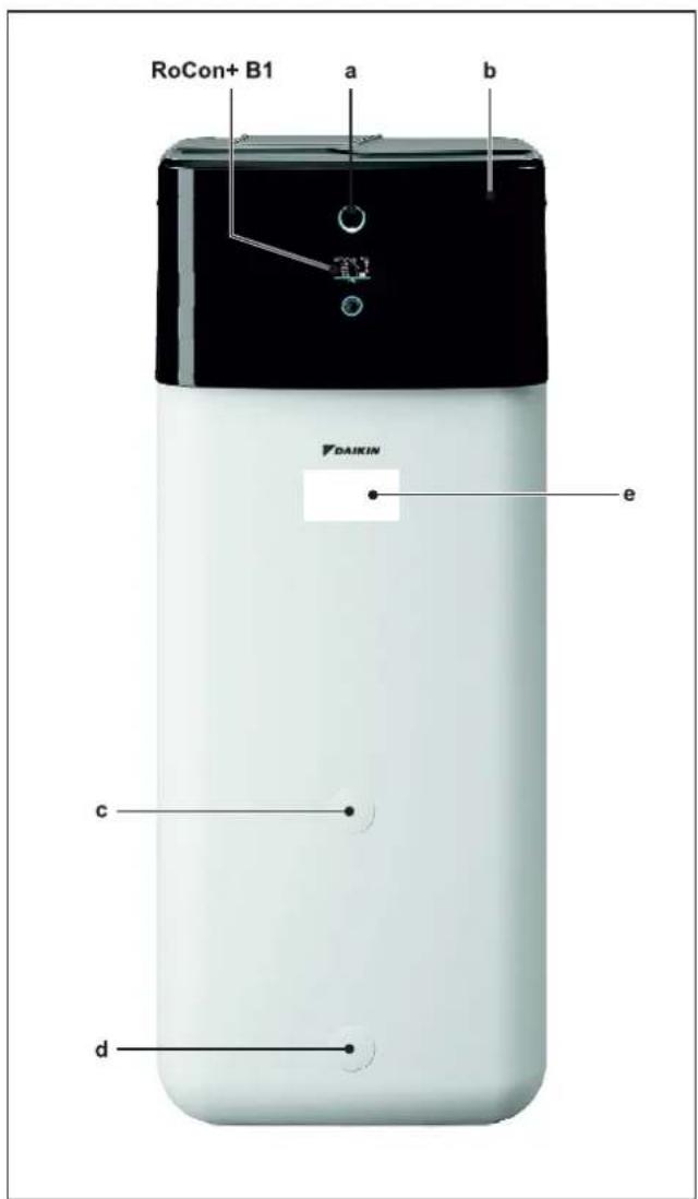
2-1 Design and components – Outside of the device
a Status indicator
b Protective cover
c Mount for handle
d Filling and draining connection or solar return flow connection
e Type plate
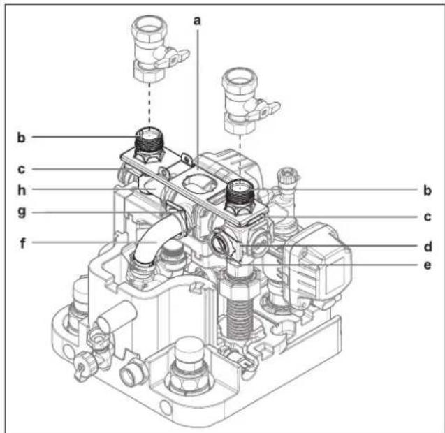
Upper side of the device
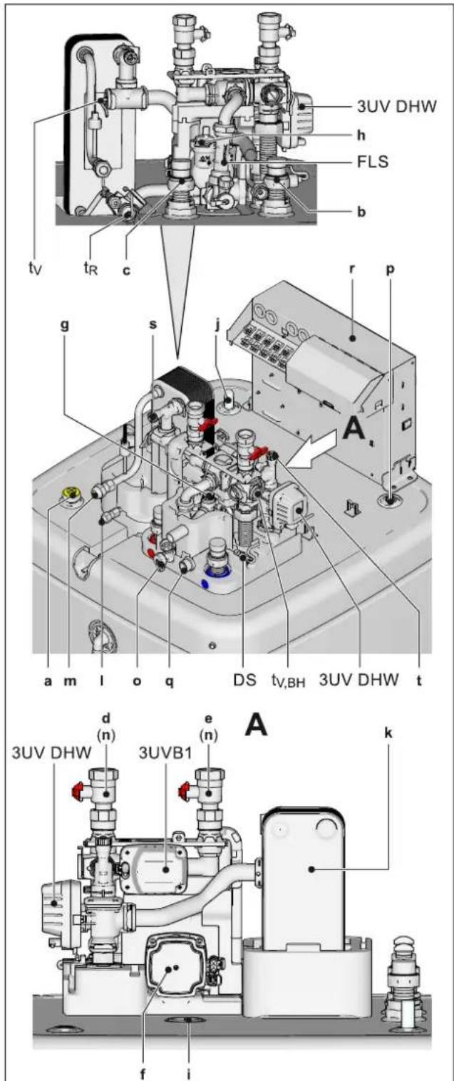
2-2 Design and components - Top of the device
a Solar flow
b Cold water connection
c Hot water
d Heating flow
e Heating return flow
f Circulation pump
g Pressure relief valve
h Automatic vent valve
i Connection for optional electrical backup heater EKBUxx
j Fill level indicator (tank water)
k Plate heat exchanger
I Connection for refrigerant fluid line
m Connection for refrigerant gas line
n Ball valve (heating circuit)
o Combined filling and draining valve (heating circuit)
p Storage tank temperature sensor
q Expansion vessel connection
r Switch box
s, t Manual air purge valves
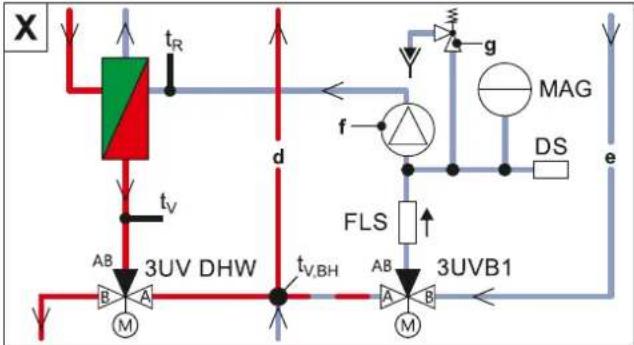
3UVB1 3-way changeover valve (internal heat generator circuit)
3UV DHW 3-way changeover valve (hot water/heating)
DS Pressure sensor
FLS FlowSensor
t_R Return temperature sensor
t_v,BH Backup heater inflow temperature sensor
Internal structure...04P30D.../...08P30D...
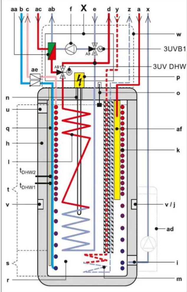
2-3 Design and components - Internal structure ...04P30D.../...08P30D... (Biv)
a Solar flow
b Cold water connection
c Hot water
d Heating flow
e Heating return flow
f Circulation pump
g Pressure relief valve
h Storage tank (polypropylene, double-walled jacket with PUR hard foam heat insulation)
i Filling and draining connection or solar return flow connection
J Mount for solar controller or handle
k Heat exchanger (stainless steel) for domestic hot water heating
I Heat exchanger (stainless steel) for storage tank charging or heating support
m Biv heat exchanger (stainless steel) for charging with external heat generator (e.g. pressurised solar system)
n Connection for optional electrical backup heater EKBUxx
o Fill level indicator (tank water)
p Optional: electric backup heater (EKBUxx)
q Submersible sensor sleeve for storage tank temperature sensor t_DIW1 and t_DIW2
r Pressureless storage tank water
s Solar zone
t Hot water zone
u Safety overflow connection
v Mount for handle
w Protective cover
x Solar return flow
y Biv flow
z Biv return flow
aa Plate heat exchanger
ab Connection for refrigerant fluid line
ac Connection for refrigerant gas line
ad Optional: Solar control and pump unit
ae Circulation stop valve (accessory)
3UVB1 3-way changeover valve (internal heat generator circuit)
3UV DHW 3-way changeover valve (hot water/heating)
DS Pressure sensor
FLS FlowSensor
MAG Expansion vessel (field supply)
t_DHW1, t_DHW2 Storage tank temperature sensor
t_R Return temperature sensor
t_v,BH Backup heater inflow temperature sensor
Internal structure...04P50D.../...08P50D...
flowchart
graph TD
    A["3UV DHW"] -->|t_V,BH| B["3UV B1"]
    B -->|AB| C["3UV DHW"]
    C -->|t_R| D["Top Flow"]
    D --> E["FLS"]
    E --> F["3UV B1"]
    F --> G["3UV DHW"]
    G --> H["3UV B1"]
    H --> I["FLS"]
    I --> J["3UV DHW"]
    J --> K["3UV B1"]
    K --> L["FLS"]
    L --> M["3UV DHW"]
    M --> N["3UV B1"]
    N --> O["FLS"]
    O --> P["3UV DHW"]
    P --> Q["3UV B1"]
    Q --> R["FLS"]
    R --> S["3UV DHW"]
    S --> T["3UV B1"]
    T --> U["FLS"]
    U --> V["3UV DHW"]
    V --> W["3UV B1"]
    W --> X["FLS"]
    X --> Y["3UV DHW"]
    Y --> Z["3UV B1"]
    Z --> AA["FLS"]
    AA --> AB["3UV DHW"]
    AB --> AC["3UV B1"]
    AC --> AD["FLS"]
    AD --> AE["3UV DHW"]
    AE --> AF["3UV B1"]
    AF --> AG["FLS"]
    AG --> AH["3UV DHW"]
    AH --> AI["3UV B1"]
    AI --> AJ["FLS"]
    AJ --> AK["3UV DHW"]
    AK --> AL["3UV B1"]
    AL --> AM["FLS"]
    AM --> AN["3UV DHW"]
    AN --> AO["3UV B1"]
    AO --> AP["FLS"]
    AP --> AQ["3UV DHW"]
    AQ --> AR["3UV B1"]
    AR --> AS["FLS"]
    AS --> AT["3UV DHW"]
    AT --> AU["3UV B1"]
    AU --> AV["FLS"]
    AV --> AW["3UV DHW"]
    AW --> AX["3UV B1"]
    AX --> AY["FLS"]
    AY --> AZ["3UV DHW"]
    AZ --> BA["3UV B1"]
    BA --> BB["FLS"]
    BB --> BC["3UV DHW"]
    BC --> BD["3UV B1"]
    BD --> BE["FLS"]
    BE --> BF["3UV DHW"]
    BF --> BG["3UV B1"]
    BG --> BH["FLS"]
    BH --> BI["3UV DHW"]
2-4 Design and components - Internal structure ...04P50D/...08P50D... (Biv)
a Solar flow
b Cold water connection
c Hot water
d Heating flow
e Heating return flow
f Circulation pump
g Pressure relief valve
h Storage tank (polypropylene, double-walled jacket with PUR hard foam heat insulation)
I Filling and draining connection or solar return flow connection
j Mount for solar controller or handle
k Heat exchanger (stainless steel) for domestic hot water heating
I Heat exchanger (stainless steel) for storage tank charging or heating support
m Biv heat exchanger (stainless steel) for charging with external heat generator (e.g. pressurised solar system) n Connection for optional electrical backup heater EKBUxx o Fill level indicator (tank water)
p Optional: electric backup heater (EKBUxx)
q Submersible sensor sleeve for storage tank temperature sensor t_DHW1 and t_DHW2
r Pressureless storage tank water
s Solar zone
t Hot water zone
u Safety overflow connection
v Mount for handle
w Protective cover
x Solar return flow
v Biv flow
z Biv return flow
aa Plate heat exchanger
ab Connection for refrigerant fluid line
ac Connection for refrigerant gas line
ad Optional: Solar control and pump unit
ae Circulation stop valve (accessory)
af Solar flow layering pipe
3UVB1 3-way changeover valve (internal heat generator circuit) 3UV DHW 3-way changeover valve (hot water/heating)
DS Pressure sensor
FLS FlowSensor
MAG Expansion vessel (field supply)
t_DHW1, t_DHW2 Storage tank temperature sensor t_R Return temperature sensor
t_v,BH Backup heater inflow temperature sensor
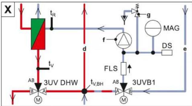
2.2 Function of the 3-way changeover valves
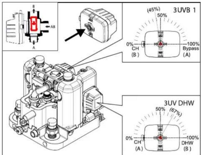
2-5 Function of 3-way changeover valve
3 Set-up and installation

WARNING
Cooling systems (heating pumps), climate control systems and heating devices that have been set up and installed incorrectly can both endanger human life and health and be impaired in their function.
- Work on the indoor unit (such as set-up, repair, connection and initial commissioning, for example) must only be carried out by persons who are authorised, who have successfully completed qualifying technical or vocational training for the respective activity and who have taken part in advanced training sessions recognised by the relevant responsible authority. These include, in particular, certified heating engineers, qualified electricians and HVAC specialists who, because of their professional training and expert knowledge, have experience in the professional installation and maintenance of heating, cooling and air conditioning systems and heat pumps.
Incorrect set-up and installation would render the manufacturer's guarantee for the unit void. If you have questions, please contact our Technical Customer Service.
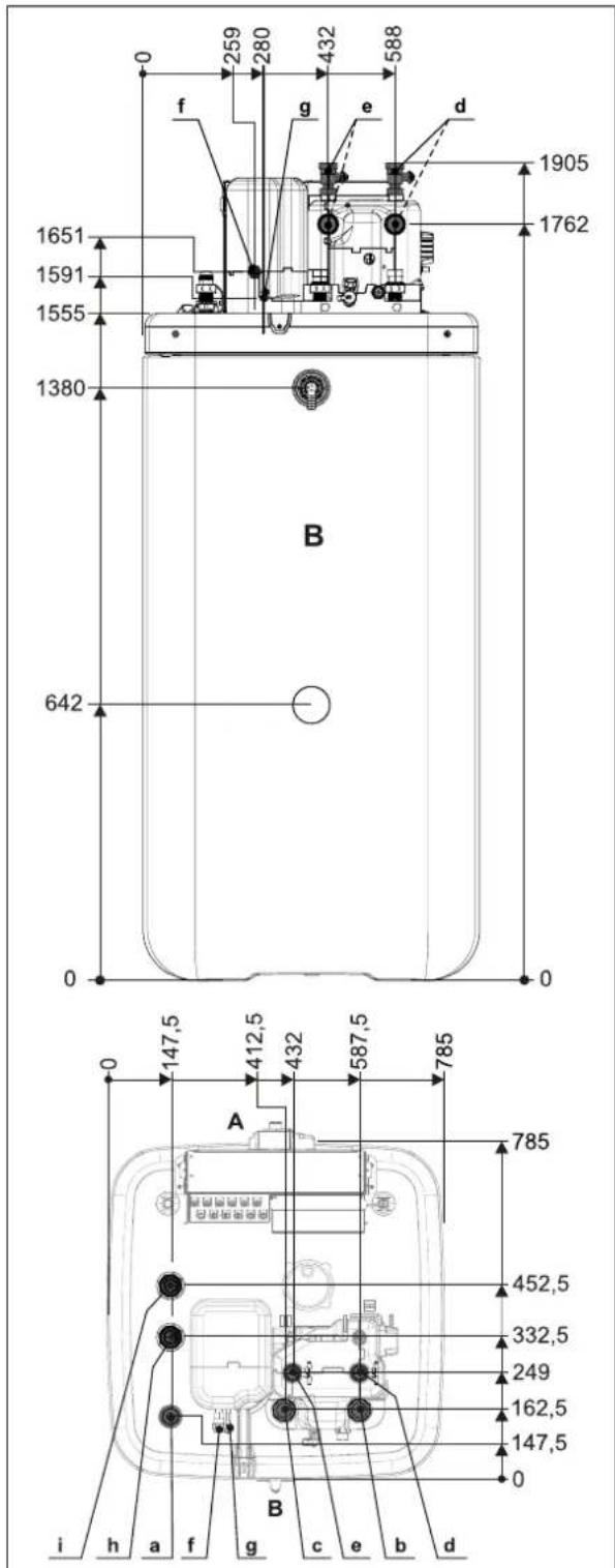
3.1 Dimensions and connection dimensions
Dimensions ...04P30D.../...08P30D...
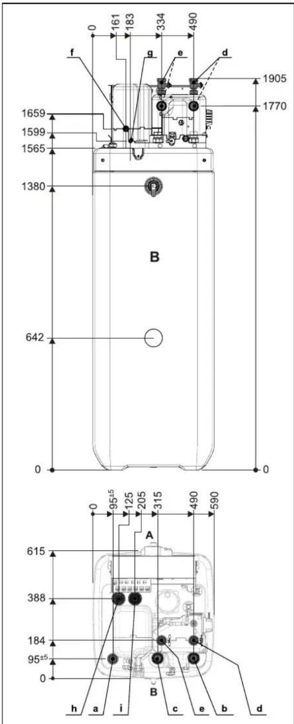
3-1 Dimensions ...04P30D.../...08P30D...
a Solar flow
b Domestic cold water
c Hot water
d Heating flow
e Heating return flow
f Connection for refrigerant gas line
g Connection for refrigerant fluid line
h Biv flow (...Biv type only)
i Biv return flow (...Biv type only)
A front
B rear
3 Set-up and installation
Dimensions ...04P50D.../...08P50D...
3-2 Dimensions ...04P50D.../...08P50D...
a Solar flow
b Domestic cold water
c Hot water
d Heating flow
e Heating return flow
f Connection for refrigerant gas line
g Connection for refrigerant fluid line
h Biv flow (...Biv type only)
i Biv return flow (...Biv type only)
A front
B rear
3.2 Transport and delivery

WARNING
When unfilled, the indoor unit is top-heavy and could tip over during transport, which could put persons in danger or damage the device.
- Secure the indoor unit well, transport carefully, use the handles.
The indoor unit is delivered on a pallet. All industrial trucks, such as lifting trucks and forklift trucks, are suitable for transport.
Scope of delivery
- Indoor unit (pre-mounted),
- Bag of accessories,
- Document pack.
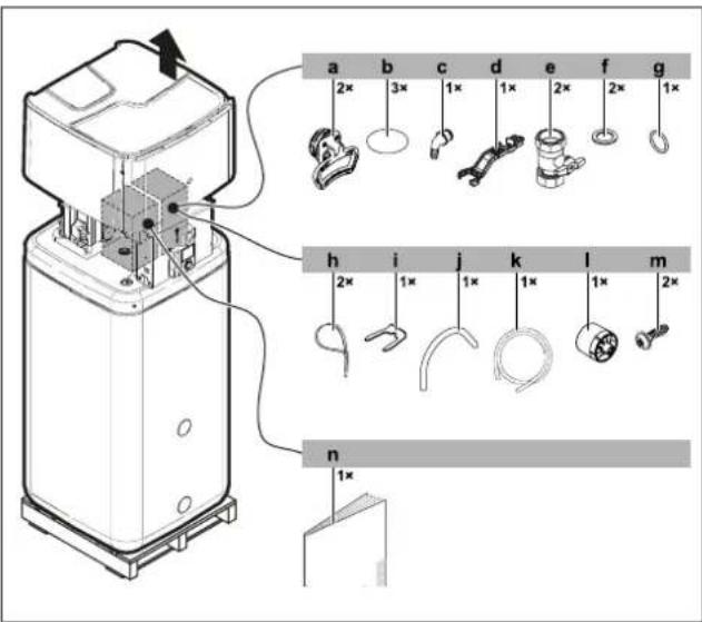
3–3 Scope of delivery
a Handles (only required for transport)
b Cover screen
c Hose connecting piece for safety overflow
d Fitting spanner
e Ball valve
f Flat gasket
g O-ring
h Cable tie
i Securing clip
j Venting hose
k Condensate drain hose
I Controller rotary switch
m Hood screws
n Document pack
For further accessories for the indoor unit, see price list.
3.3 Installing the heat pump
3.3.1 Selecting the installation site

CAUTION
If the total refrigerant charge in the system is ≥ 1.84 kg, it is essential to comply with additional requirements for minimum footprint and minimum ventilation openings.
Observe "6.4 Minimum floor area and ventilation openings" [▶ 34].
Information on the total refrigerant charge can be found on the type plate of the outdoor unit. Please follow the installation instructions.
The installation site of the indoor unit must meet the minimum requirements below (see also "1.2.3 Installation room" [▶ 6]).
Installation area
- The base must be level and smooth and have sufficient ground load-bearing capacity of 1050kg / m^2 plus safety factor. Install a pedestal if necessary.
- Observe the installation dimensions (see "3.1 Dimensions and connection dimensions" [▶ 11]).
Minimum distance

DANGER: RISK OF BURNING/SCALDING
The plastic wall of the storage tank on the indoor unit can melt under the effects of external heat ( >80^ ) and, in the extreme case, can catch fire.
- Only install the indoor unit at a minimum clearance of 1 m from other heat sources (>80°C) (e.g. electrical heater, oil heater, chimney) and combustible material.

CAUTION
p=0 If the indoor unit is not installed at a sufficient distance below the flat solar panels (the top edge of the storage tank is higher than the bottom edge of the solar panels), the unpressurised solar system in the outdoor area will not be able to drain completely.
- When a solar connection is used, install the indoor unit low enough under the flat solar panels (observe the minimum gradient of the solar connection lines).
Recommended minimum distances:
From the wall: (rear) ≥100 mm, (sides) ≥500 mm
From the ceiling: ≥1200 mm, at least 480 mm.
Distances from the outdoor unit:
When selecting the installation location, the data in the table "3-1" [▶ 13] must be taken into account.
3-1
| Maximum refrigerant piping length between the indoor and outdoor units | 30 m |
| Minimum refrigerant piping length between the indoor and outdoor units | 3 m |
| Maximum height difference between the indoor and outdoor units | 20 m |
3.3.2 Installing the device

WARNING
When unfilled, the indoor unit is top-heavy and could tip over during transport, which could put persons in danger or damage the device.
- Secure the indoor unit well, transport carefully, use the handles.
Precondition
- The installation site complies with applicable country-specific regulations and meets the minimum requirements described in "3.3.1 Selecting the installation site" [▶ 12].
Set-up
1 Remove the packaging and dispose of it in an environmentally sound manner.
2 Pull off the cover screens from the storage tank (item b) and unscrew the threaded fittings (item c) from the openings at which the handles are to be fitted.
3 Screw the handles (item a) into the now uncovered threaded holes.
4 Carefully transport the indoor unit to the installation site, use the handles.
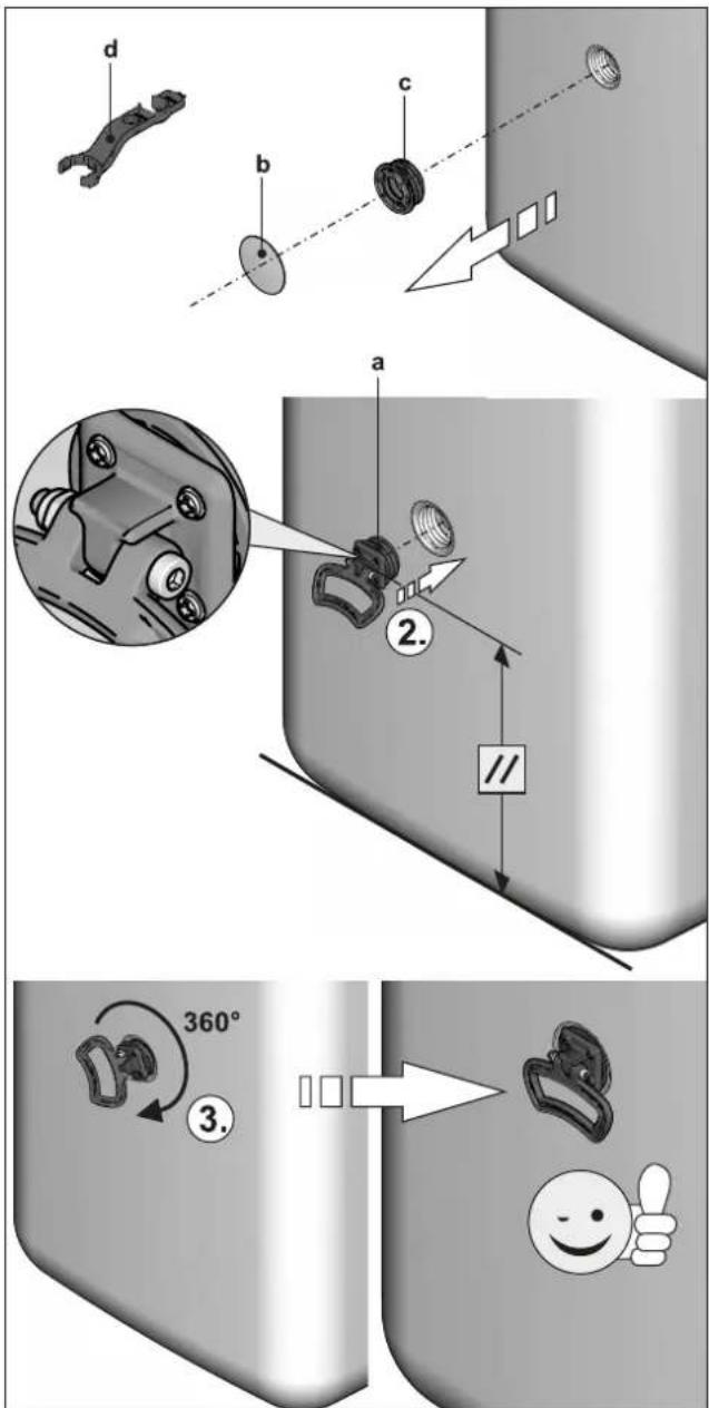
3-4 Installing the handles
a Handle
b Cover screen
c Threaded piece
d Fitting spanner
5 Install the indoor unit at the installation site.
- When setting up the unit in a cabinet, behind panels or in other restricted conditions, sufficient ventilation (e.g. using ventilation gratings) must be ensured. If the total refrigerant charge in the system is ≥ 1.84 kg, further requirements of the ventilation openings must be met (see "6.4 Minimum floor area and ventilation openings" [▶ 34]).
3.4 Preparing the device for installation
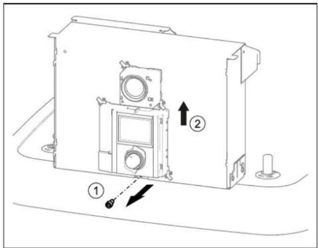
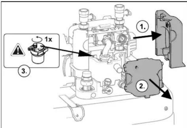
3.4.1 Remove the front screen
1 Undo the screws (1.).
3 Set-up and installation
2 Press the lateral holding burls upwards with your fingers (2.), stem from above with the thumbs.
3 Remove the front screen to the front (3.).
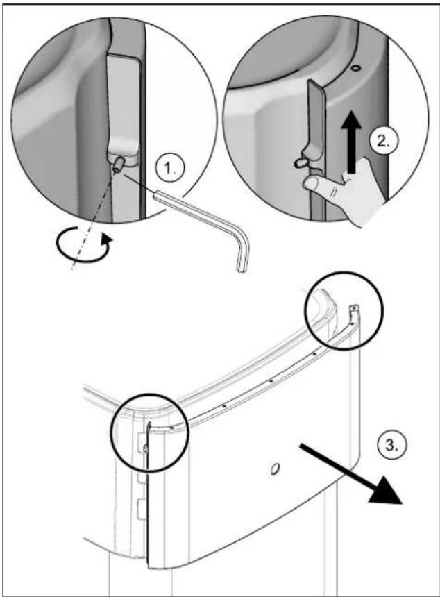
3-5 Remove the front screen
3.4.2 Remove the protective cover
1 Unhook the protective cover from the rearward facing holding burls (1.), lift at the back (2.) and remove to the front (3.).
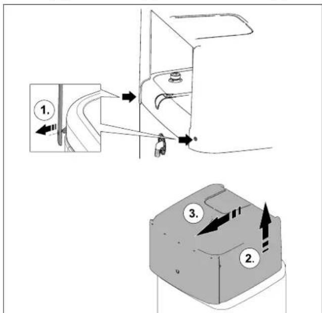
3-6 Remove the protective cover
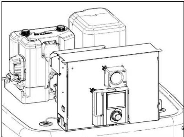
natural_image
Technical line drawing of a mechanical device with mounting brackets and housing (no text or symbols)3-7 Without protective cover
3.4.3 Moving the switch box to the service position
To facilitate work on the hydraulics of the indoor unit, the switch box can be moved to the service position.
1 Loosen the screws (a) of the holder of the switch box.
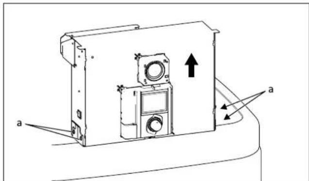
3-8 Moving the switch box to the service position
2 Remove the switch box from the front and insert it into the bracket with the hooks on the rear brackets.
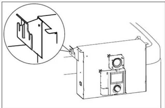
natural_image
Technical line drawing of a mechanical assembly with an inset showing a close-up of a component detail (no text or symbols present)3-9 Switch box in the service position
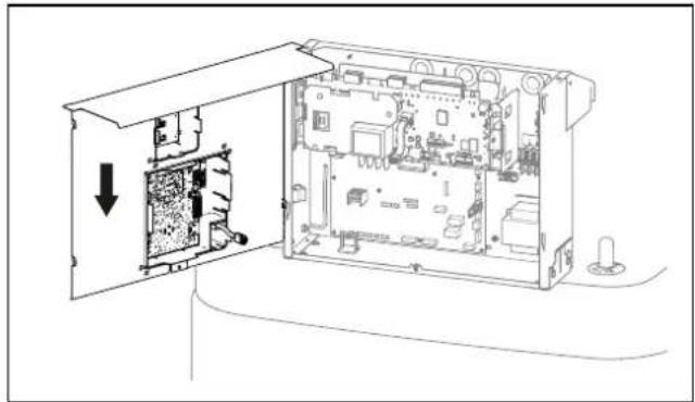
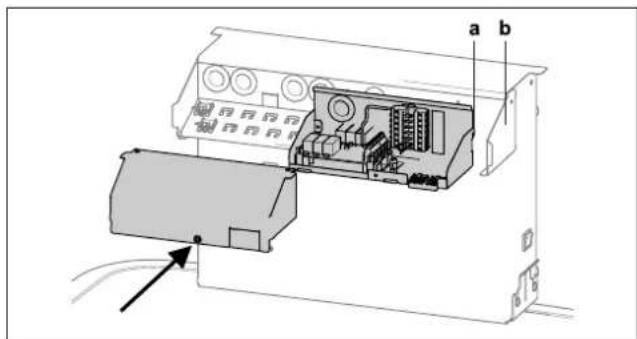
3.4.4 Open the switch box
To make the electrical connections, the switch box itself must be opened. This can be done in both the normal and the service position.
1 Loosen the front screw.
2 Push the cover upwards and pull it away to the front.
3-10 Open the switch box
3 Hook in the cover on the switch box with the lateral hooks.
natural_image
Technical line drawing of an open electronic device showing internal components and a directional arrow (no text or symbols)3–11 Hooking in the cover
3.4.5 Removing the bottom thermal insulation

CAUTION
The thermal insulation consists of pressure-sensitive EPP moulded parts that can be easily damaged if not handled correctly.
- Only remove the thermal insulation in the order stated below and in the stated directions.
- Do not use force.
- Do not use tools.
1 Remove the thermal insulation in the following order:
- Pull the side insulating element off horizontally (item a).
- Pull the rear insulating element off horizontally (item b).
- Pull the front insulating element off horizontally (item c).
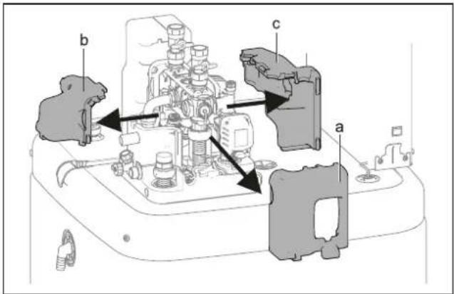
3–12 Removing the top thermal insulation
a Side insulating element
b Rear insulating element
c Front insulating element
2 As required: Remove the bottom thermal insulation in the following order:
- Pull the side insulating element off vertically (item a).
- Pull the rear insulating element off vertically (item b).
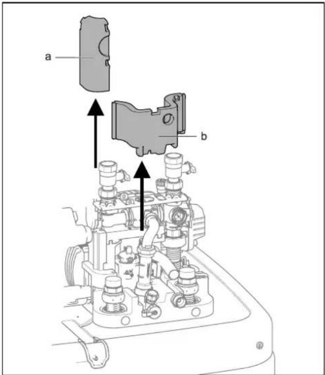
3–13 Removing the bottom thermal insulation
a Side insulating element
b Rear insulating element

INFORMATION
The thermal insulation is installed in reverse order.
3.4.6 Opening the air purge valve
1 Removing the thermal insulation (see "3.4.5 Removing the bottom thermal insulation" [▶ 15]).
2 Open the air purge valve on the pump by one turn.
3 Set-up and installation
3-14 Opening the air purge valve
3.4.7 Aligning the connections of the heating inflow and return flow

CAUTION
When working on the hydraulics, pay attention to the installation position of the O-rings to avoid damaging them and causing leaks.
- Always place O-rings on the part to be inserted after disassembly or before assembly (see "15 Hydraulic system plug connectors" [▶ 16]).
- The heating lines must be connected free of tension via the plug connectors. Establish a suitable strain relief especially when connecting with flexible lines (not open to diffusion!) (see "3-28 Supporting rear-facing hydraulic lines" [▶ 20]).
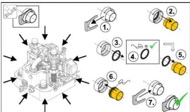
3–15 Hydraulic system plug connectors

CAUTION
If the securing clips cannot be put on properly, the couplings can be detached from their mountings to ensure a very strong or continuous escape of liquid can occur.
- Before putting on a securing clip, make sure that the securing clip engages in the coupling groove. To do so, insert the coupling far enough into the mounting that the groove is visible through the securing clip mounting.
- Insert the securing clip up to the end stop.
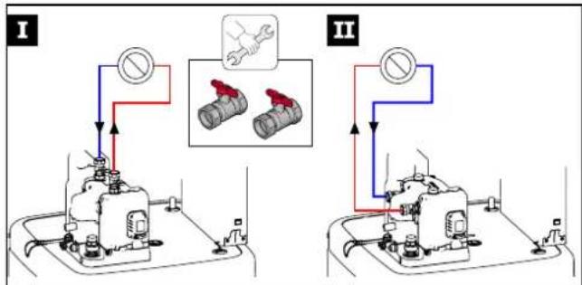
The connections of the heating inflow and return flow can be directed upwards or backwards in order to adapt it optimally to the structural conditions of the installation site.
flowchart
graph TD
    subgraph I
        A["Valve"] --> B["Pressure Gauge"]
        B --> C["Main Valve"]
        C --> D["Valve"]
        D --> E["Valve"]
        E --> F["Valve"]
        F --> G["Valve"]
        G --> H["Valve"]
        H --> I["Valve"]
        I --> J["Valve"]
        J --> K["Valve"]
        K --> L["Valve"]
        L --> M["Valve"]
        M --> N["Valve"]
        N --> O["Valve"]
        O --> P["Valve"]
        P --> Q["Valve"]
        Q --> R["Valve"]
        R --> S["Valve"]
        S --> T["Valve"]
        T --> U["Valve"]
        U --> V["Valve"]
        V --> W["Valve"]
        W --> X["Valve"]
        X --> Y["Valve"]
        Y --> Z["Valve"]
        Z --> AA["Valve"]
        AA --> AB["Valve"]
        AB --> AC["Valve"]
        AC --> AD["Valve"]
        AD --> AE["Valve"]
        AE --> AF["Valve"]
        AF --> AG["Valve"]
        AG --> AH["Valve"]
        AH --> AI["Valve"]
        AI --> AJ["Valve"]
        AJ --> AK["Valve"]
        AK --> AL["Valve"]
        AL --> AM["Valve"]
        AM --> AN["Valve"]
        AN --> AO["Valve"]
        AO --> AP["Valve"]
        AP --> AQ["Valve"]
        AQ --> AR["Valve"]
        AR --> AS["Valve"]
        AS --> AT["Valve"]
        AT --> AU["Valve"]
        AU --> AV["Valve"]
        AV --> AW["Valve"]
        AW --> AX["Valve"]
        AX --> AY["Valve"]
        AY --> AZ["Valve"]
        AZ --> BA["Valve"]
        BA --> BB["Valve"]
        BB --> BC["Valve"]
        BC --> BD["Valve"]
        BD --> BE["Valve"]
        BE --> BF["Valve"]
        BF --> BG["Valve"]
        BG --> BH["Valve"]
        BH --> BI["Valve"]
        BI --> BJ["Valve"]
        BJ --> BK["Valve"]
        BK --> BL["Valve"]
        BL --> BM["Valve"]
        BM --> BN["Valve"]
        BN --> BO["Valve"]
        BO --> BP["Valve"]
        BP --> BQ["Valve"]
        BQ --> BR["Valve"]
        BR --> BS["Valve"]
        BS --> BT["Valve"]
        BT --> BU["Valve"]
        BU --> BV["Valve"]
        BV --> BW["Valve"]
        BW --> BX["Valve"]
        BX --> BY["Valve"]
        BY --> BZ["Valve"]
3–16 Variants for aligning the heating infeed and return flow
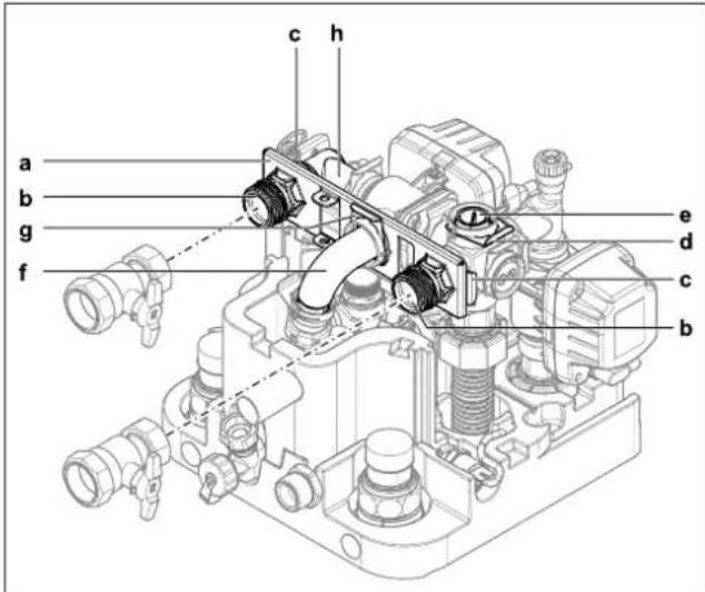
The device is supplied with upwards aligned connections as standard. The following conversion steps are required in order to direct the connections to the rear out of the device:
1 Remove the protective cover and top thermal insulation (see "3.4.2 Remove the protective cover" [▶ 14], "3.4.5 Removing the bottom thermal insulation" [▶ 15]).
2 Pull the two securing clips off the connection couplings (item c).
3 Pull off the two connection couplings (item b).
4 Remove the retaining plate (item a).
5 Pull off the sealing plug securing clip (item d).
6 Pull out the sealing plug (item e).
7 Turn the elbow (item h) 90° to the rear.
8 Pull the securing clip off the manifold (item g).
3-17 Aligning the heating inflow and return flow connections upwards
a Retaining plate
b Connection coupling
c Securing clip of the connection couplings
d Securing clip of the sealing plug
e Sealing plug
f Manifold
g Securing clip of the manifold
h Elbow
9 Carefully pull the manifold (item f) so far backwards out of its horizontal mounting that the retaining plate (" 2-18 Heating inflow and return flow connections aligned to the rear" [▶ 17], item a) can be pushed vertically in between.
10 Slide the retaining plate between the manifold and its horizontal mounting, and insert the manifold (item f) back into its mounting through the middle hole of the retaining plate.
11 Secure the manifold with securing clip (item g) in its mounting again.
12 Insert the two connection couplings (item b) through the retaining plate into the lateral mountings.
13 Secure the two connection couplings with securing clips (item c) in their mountings.
14 Insert the sealing plug (item e) in the upper mounting.
15 Secure the sealing plug with securing clip (item d).
3–18 Heating inflow and return flow connections aligned to the rear
a Retaining plate
b Connection coupling
c Securing clip of the connection couplings
d Securing clip of the sealing plug
e Sealing plug
f Manifold
g Securing clip of the manifold
h Elbow
16 Cut out side openings in the thermal insulation (item a) using a suitable tool.

3–19 Cut-out in thermal insulation
a Side openings in the thermal insulation
3.4.8 Making the hood opening
1 With the heating inflow and return flow directed upwards: Cut the hood along the perforation with a suitable tool.
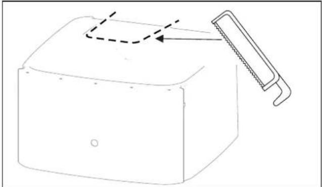
natural_image
Line drawing of a mechanical component with a saw cutting through it (no text or symbols)3–20 Making the hood opening
3.4.9 Installing the rotary switch of the controller
1 Place the rotary switch on the rotary switch holder of the RoCon + HP1 and press it on.
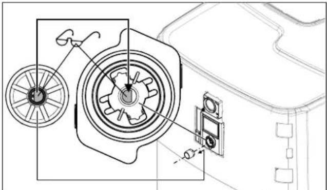
natural_image
Technical line drawing of a mechanical assembly with gears and components (no text or symbols)3-21 Putting on the rotary switch
3.4.10 Securing the hood
After the installation is fully completed:
1 Attach the screws for fixing the hood (accessory bag).
2 Place the front cover straight over the rotary switch of the RoCon+ HP1. Press on the top and bottom until the front screen is securely engaged again.
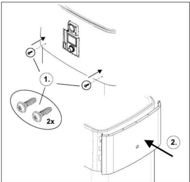
3–22 Securing the hood
3 Set-up and installation
3.5 Installing optional accessories
3.5.1 Installation of electric backup heater (EKBUxx)

INFORMATION
If the ceiling height is low, the storage tank must be tilted to install the backup heater when empty. This must be done before any further installation steps.
The indoor unit provides the option of installing an electrical auxiliary heater (backup heater EKBUxx). For example, renewable energy can be used as an additional heat source.

INFORMATION
A separate manual containing instructions about installation and operation is included with this component.
3.5.2 Installation of the external heat generator connection set (EKBUHSWB)
The connection set for external heat generators must be installed to control an electrical backup heater or another external heat generator.
1 Open the housing by removing the screw.
2 Remove additional components from the housing (strain relief clip, cable tie, grommet).
3 Attach the connection set to the switch box of the indoor unit. To do this, insert the hooks (item a) of the connection set into the slots of the switch box (item b); then press the connection set downwards.
3–23 Fitting the connection set
a Hooks
b Slot
4 Attach the grommet (item a) to the bushing between the connection set and the switch box.
5 Attach the fastening rivet (item b).

3-24 Cable gland
a Grommet
b Fastening rivet
6 Guide the cable of the Ultra EHS PCB through the cable grommet and connect it to the RoCon BM2C (see 3-38 Connection on the RTX-EHS PCB" [▶ 25]).
7 After the installation and the electrical connections (see "3.6 Water connection" [▶ 19] or "3.7 Electrical connection" [▶ 20]) have been completed, replace the cover and close it with the screw.
3.5.3 Installation of the DB connection kit
The optional DB connection kit allows better access for connecting the DrainBack pipe (solar feed).
3-25 DB connection kit
a DB pipe connection (solar flow)
b FlowSensor (not part of the DB connection kit, but included with EKSRPS4)
c Flow rate limiter (FlowGuard)
d Solar flow connection | n=0 on the storage tank
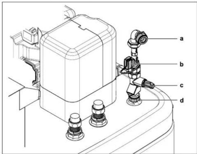
3.5.4 Installation of the P connection kit
The optional P connection kit for Biv device types allows better access for connecting the flow and return flow lines of a pressurised solar system or another external heat generator on the storage tank. The kit contains two thermally insulated corrugated pipes that are connected to the connections of the storage tank via a union nut. At the other end of the corrugated pipes there is an adapter for different connection sizes of the supply and return pipes.
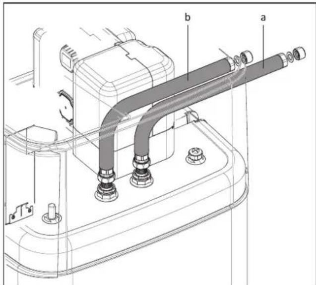
3–26 P connection kit for Biv device types
a Connection for flow (red)
b Connection for return flow (blue)
3.6 Water connection
Important information

CAUTION
If the indoor unit is connected to a heating system with steel pipes, radiators or non-diffusion-proof floor heating pipes, sludge and chips can enter the hot water storage tank and cause blockages, local overheating or corrosion damage.
- Rinse supply lines before filling the device.
- Rinse out the heat distribution network (in the existing heating system).
- Install a dirt filter or sludge separator in the heating return flow (see "1.2.6 Heating system and sanitary connection" [▶ 7]).

CAUTION
If the indoor unit is connected to a cold water line where steel pipes are used, chips can get into the stainless steel corrugated pipe heat exchanger and remain there. This can lead to contact corrosion damage and subsequently to leakage.
- Flush the feed pipes before filling the heat exchanger.
- Install the dirt filter in the cold water supply (e.g. SAS 1 or SAS 2).

CAUTION: BIV only
If the heat exchanger for pressurised solar system charging (see "3.1 Dimensions and connection dimensions" [▶ 11], items h + i) is connected to an external heater (e.g. wood burning boiler) the indoor unit can be damaged or destroyed due to an excessively high flow temperature at these connections.
- The flow temperature of the external heater should be limited to max. 95°C.

CAUTION
Corrosion may be caused by air entering the heating water network and by a quality of the heating water that does not comply with the requirements in accordance with "1.2.5 Requirements for heating and storage water" [▶ 6]. Corrosion products (particles) thus created may clog pumps and valves and cause malfunctions.
- Device may not be connected by permeable, flexible lines.

INFORMATION
Any steam or heating water escaping from the safety valve must be drained by a suitable blow-off line with constant gradient in a frost-protected, safe and observable manner.
A expansion vessel suitably sized and preset for the heating system must be connected to the Daikin Altherma 3 R ECH₂O. There may not be any hydraulic blocking elements between the heat generator and the diaphragm expansion vessel.
We recommend installing a mechanical manometer for filling the heating system.
- For potable water lines, observe the provisions of EN 806, DIN 1988 and the additional applicable national regulations for potable water installation.
- Install the indoor unit close to the withdrawal point to dispense with the need for a circulation line. If a circulation line is permissible and mandatory according to local regulations, it must be installed according to the schematic diagrams in "Hydraulic System Connection" in the reference manual for the fitter.
3.6.1 Minimum water volume
A water volume of at least 5 litres must be ensured in the heating circuit. The internal water volume of the heat pump internal unit is not included in this calculation.

INFORMATION
In critical applications or in rooms with high heating loads, additional water volume may be required.

CAUTION
If several heating circuits are connected to the heat pump indoor unit, it is important that the minimum water volume is guaranteed even if only one heating circuit is open.
3.6.2 Connecting hydraulic lines

DANGER: RISK OF BURNING/SCALDING
There is a danger of scalding at hot water temperatures over 65^ C. This is possible when using solar energy if an external heater is connected, the Legionella protection is activated, or the target hot water temperature is set to be greater than 65^ C or if the Smart-Grid function is activated.
- Install scalding protection (hot water mixer device (e.g. VTA32)).

INFORMATION
The indoor unit is equipped with a pressure sensor. The system pressure in monitored electronically and can be displayed with the device switched on.
Nevertheless, we recommend installing a mechanical manometer between the indoor unit and the expansion vessel, for example.
- Install the manometer so that it is easy to see when filling.
Prerequisite: Optional accessories (e.g. solar, backup heater) are mounted on the Daikin Altherma 3 R ECHO as specified in the enclosed instructions.
1 Check the cold water connection pressure (maximum 10 bar).
- At higher pressure in the drinking water line, a pressure reducer must be installed.
2 Fix the hydraulic block in place with a screwdriver.
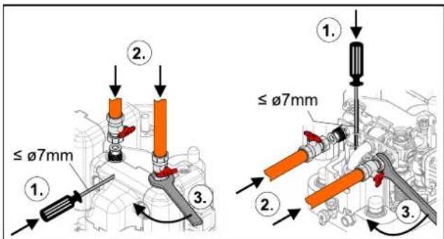
3-27 Fix the hydraulic block in place when connecting to the top (left) or to the rear (right)
3 Set-up and installation
3 Make the hydraulic connections on the indoor unit.
- Refer to "3.1 Dimensions and connection dimensions" [▶ 11] for the position and dimension of the heater connections.
- Pay attention to the stipulated tightening torque (see "6.3 Tightening torques" [▶ 34]).
- Install the line so that the sound insulation hood can be positioned easily after installation.
- Connect the water for filling or refilling the heating system as specified by EN 1717/EN 61770 to avoid contamination of drinking water by return flow.
- For rear-facing connections: Support hydraulic lines suitably according to the spatial conditions.
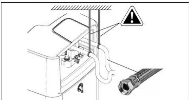
3–28 Supporting rear-facing hydraulic lines
4 Connect the blow-off line to the safety over-pressure valve and expansion vessel in accordance with EN 12828.
- Any steam or heating water that may escape must be drained by a suitable blow-off line with constant gradient in a frost-protected, safe and observable manner.
- Install the line in such a way that the protective cover is simple to put on after assembly.
- Check the seat of the drain hose on the safety pressure relief valve. If necessary, connect and install a separate hose.
5 Connecting a expansion vessel.
- Connect a suitably dimensioned and preset expansion vessel for the heating system. There may not be any hydraulic blocking elements between the heat generator and the safety valve.
- Position the expansion vessel in an easily accessible place (maintenance, parts replacement).
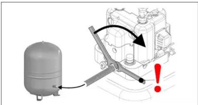
3–29 Mounting the expansion vessel
6 Carefully insulate pipework against heat loss and to avoid condensation (insulation thickness at least 20 mm).
- Water shortage protection: The pressure and temperature monitoring of the controller shuts off and locks the indoor unit safely if there is a shortage of water. No additional water shortage protection is needed in the construction.
- Avoid damage caused by deposits and corrosion: see "1.2.5 Requirements for heating and storage water" [▶ 6]
3.6.3 Connecting the drain
1 Screw the hose connection piece for safety overflow (part of the accessory bag) into the intended connection ("2-3 Design and components - Internal structure ...04P30D.../...08P30D... (Biv)" [▶9], item u) and connect it with the drain hose.
- Use transparent drain hose (draining water must be visible).
- Connect the drain hose to an adequately dimensioned waste water installation.
- Drain should not be lockable.
2 Attach the condensate drain hose (part of accessory bag) to its connection on the cover.
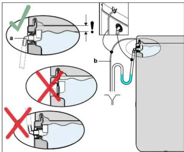
3–30 Connection of the overflow hose
a Hose connecting piece for safety overflow b Condensate drain hose
3.7 Electrical connection

DANGER: RISK OF ELECTROCUTION
Touching live parts can result in an electric shock and lead to potentially fatal injuries and burns.
- Before beginning work on live parts, disconnect all of the circuits of the system from the power supply (switch off external main switch, disconnect fuse) and secure against unintentional restart.
- Establishment of the electrical connection and work on electrical components should only be performed by electrical technicians in compliance with valid standards and guidelines as well as the specifications of the energy supply company and the instructions in this manual.
- The installation of earth leakage circuit breakers (GFCI) is mandatory, as shown in the pictures of this document.
- Never make constructional changes to connectors or other electrical equipment components.
- Device covers and service panels must be replaced as soon as the work is completed.

CAUTION
Increased temperatures can occur in the switch box of the indoor unit during operation. This can result in currently-carrying wires from reaching higher temperatures during operation due to self-heating. For this reason, these lines need to have a continuous use temperature of 90°C.
- For the following connections, only use cables with a long-term use temperature ≥ 90^ : Heat pump outdoor unit and optional: Electric backup heater (EKBUxx)

CAUTION
If the mains cable of the indoor unit is damaged, it must be replaced by the manufacturer or his customer service or a similarly qualified person to avoid hazards.
All electronic control and safety devices of the indoor unit are connected ready for use and tested. Modifications on the electrical installation are dangerous and prohibited. The operator alone bears responsibility for any resulting damage.
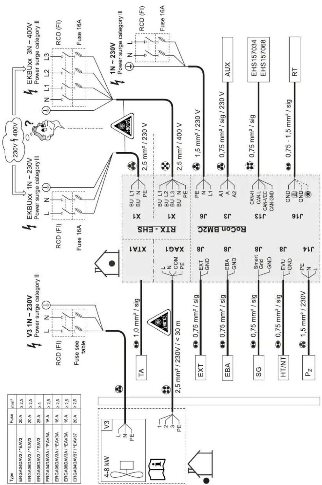
3.7.1 Overall connection diagram
flowchart
graph TD
    A["Type"] --> B["Fuse mm²"]
    B --> C["ERGA04DAV3 / *EAV3 20A ≥2,5"]
    B --> D["ERGA06DAV3 / *EAV3 20A ≥2,5"]
    B --> E["ERGA08DAV3 / *EAV3 25A ≥4"]
    B --> F["ERGA04DAV3A / *EAV3A 16A ≥2,5"]
    B --> G["ERGA06DAV3A / *EAV3A 16A ≥2,5"]
    B --> H["ERGA08DAV3A / *EAV3A 16A ≥2,5"]
    B --> I["ERGA04DAV37 / *EAV37 20A ≥2,5"]

    J["V3 1N ~ 230V Power surge category III"] --> K["RCD (FI) L N ⊕"]
    K --> L["Fuse see table"]

    M["EKBUxx 1N ~ 230V Power surge category III"] --> N["RCD (FI) L N ⊕"]
    N --> O["Fuse 16A"]

    P["EKBUxx 3N ~ 400V Power surge category III"] --> Q["N L1 L2 L3 RCD (FI) Fuse 16A"]

    R["4-8 kW V3 L N PE"] --> S["TA 1.0 mm² / sig"]
    S --> T["XTA1"]
    T --> U["XAG1"]
    U --> V["RTX - EHS"]
    V --> W["X1 BU L1 BU N PE"]
    V --> X["X1 BU L1 BU L2 BU L3 BU N PE"]
    V --> Y["2.5 mm² / 230 V"]
    V --> Z["2.5 mm² / 400 V"]

    AA["EXT"] --> AB["EXT GND J8"]
    AB --> AC["J8"]
    AC --> AD["RoCon BM2C"]
    AD --> AE["J6 PE N L1"]
    AD --> AF["J3 A1 A A2"]
    AD --> AG["AUX"]

    AH["EBA"] --> AI["0.75 mm² / sig"]
    AI --> AJ["EBA GND J8"]
    AJ --> AK["J8"]
    AK --> AL["AUX"]

    AM["SG"] --> AN["0.75 mm² / sig"]
    AN --> AO["Smart Grid GND J8"]
    AO --> AP["J8"]
    AP --> AQ["J13 CAN-H CAN-L CAN-VCC CAN-GND"]
    AQ --> AR["0.75 mm² / sig"]
    AR --> AS["EHS157034 EHS157068"]

    AT["HT/NT"] --> AU["0.75 mm² / sig"]
    AU --> AV["EVU GND J8"]
    AV --> AW["J8"]
    AW --> AX["J16 GND GND ⊗"]
    AX --> AY["0.75 - 1.5 mm² / sig"]
    AY --> AZ["RT"]

    BA["Pz"] --> BB["1.5 mm² / 230V PE N L"]

    style A fill:#f9f,stroke:#333
    style B fill:#ccf,stroke:#333
    style C fill:#cfc,stroke:#333
    style D fill:#fcc,stroke:#333
    style E fill:#fcc,stroke:#333
    style F fill:#fcc,stroke:#333
    style G fill:#fcc,stroke:#333
    style H fill:#fcc,stroke:#333
    style I fill:#fcc,stroke:#333
    style J fill:#fcc,stroke:#333
    style K fill:#fcc,stroke:#333
    style L fill:#fcc,stroke:#333
    style M fill:#fcc,stroke:#333
    style N fill:#fcc,stroke:#333
    style O fill:#fcc,stroke:#333
    style P fill:#fcc,stroke:#333
    style Q fill:#fcc,stroke:#333
    style R fill:#fcc,stroke:#333
    style S fill:#fcc,stroke:#333
    style T fill:#fcc,stroke:#333
    style U fill:#fcc,stroke:#333
    style V fill:#fcc,stroke:#333
    style W fill:#fcc,stroke:#333
    style X fill:#fcc,stroke:#333
    style Y fill:#fcc,stroke:#333
    style Z fill:#fcc,stroke:#333
    style AA fill:#fcc,stroke:#333
    style AB fill:#fcc,stroke:#333
    style AC fill:#fcc,stroke:#333
    style AD fill:#fcc,stroke:#333
    style AE fill:#fcc,stroke:#333
    style AF fill:#fcc,stroke:#333
    style AG fill:#fcc,stroke:#333
    style AH fill:#fcc,stroke:#333
    style AI fill:#fcc,stroke:#333
    style AJ fill:#fcc,stroke:#333
    style AK fill:#fcc,stroke:#333
    style AL fill:#fcc,stroke:#333
    style AM fill:#fcc,stroke:#333
    style AN fill:#fcc,stroke:#333
    style AO fill:#fcc,stroke:#333
    style AP fill:#fcc,stroke:#333
    style AQ fill:#fcc,stroke:#333
    style AR fill:#fcc,stroke:#333
    style AS fill:#fcc,stroke:#333
    style AT fill:#fcc,stroke:#333
    style AU fill:#fcc,stroke:#333
    style AV fill:#fcc,stroke:#333
    style AW fill:#fcc,stroke:#333
    style AX fill:#fcc,stroke:#333
    style AZ fill:#fcc,stroke:#333
3–31 Overall connection diagram – for the electrical connection during the device installation (for the legend and pin assignment of the PCB, see "6.5 Electrical connection diagram" [▶ 36])
3.7.2 Position of the PCBs and terminal strips
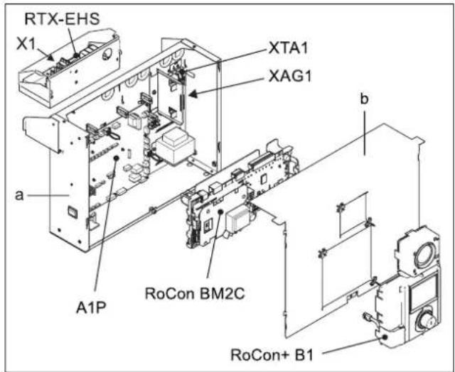
3–32 Position of the PCBs and terminal strips
a Switch box
b Switch box cover
A1P PCB (heat pump basic control)
RoCon+ B1 Controller control panel
RoCon BM2C PCB (basic controller module)
RTX-EHS PCB (backup heater)
X1 Terminal strip for backup heater mains connection
XAG1 Heat pump outdoor unit plug connection
XTA1 Outdoor temperature sensor terminal strip T
3.7.3 Mains connection
A flexible cable for the mains connection is already connected inside the device.
1 Check the supply voltage ( 230 V, 50 Hz).
2 Disconnect the junction box of the domestic installation.
3 Connect the cable for connecting the indoor unit to the mains to the domestic installation's junction box (isolator according to EN 60335-1) via an all-pole separating main switch to be installed in the building. Ensure that the polarity is correct.
3.7.4 General information on the electrical connection
1 Check the supply voltage.
2 Set the mains switch to "Off".
3 Switch off the circuit breaker in the junction box of the domestic power supply.
4 Open the switch box (see "3.4.4 Open the switch box" [▶ 14]).
5 Insert the cable through one of the cable glands into the interior of the switch box. When cutting and laying cables to be connected, make sure that the switch box can be brought into the service position without any tension.
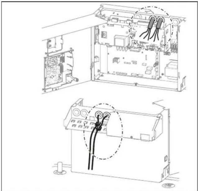
natural_image
Technical line drawing of an open electronic device showing internal components and wiring connections (no text or symbols)3–33 Cable gland
6 Make electrical connections according to "3.7.1 Overall connection diagram" [▶ 22] and the following sections.
7 Effective strain relief in the switch box by means of cable ties must be ensured for all cables connected to the indoor unit and their holding force checked.
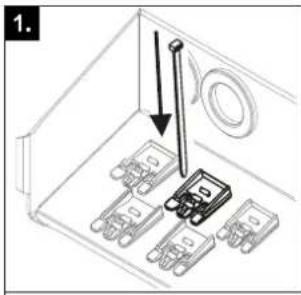
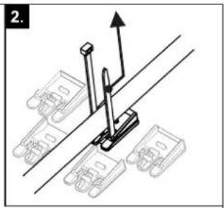
natural_image
Mechanical assembly diagram showing a lever mechanism with mounting brackets and a directional arrow (no text or symbols)

3–34 Establishing and checking the strain relief
8 After the installation is complete: Close the switch box again and, if necessary, move it to the normal position.
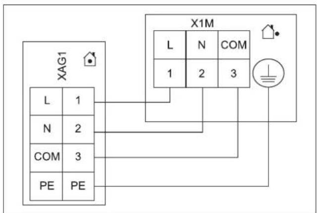
3.7.5 Connecting the heat pump outdoor unit

INFORMATION
A separate manual containing instructions about installation and operation is included with this component.
1 Follow the installation steps in "3.7.4 General information on the electrical connection" [▶ 23].
2 Connect the heat pump outdoor unit to the XAG1 terminal strip.
3 Set-up and installation
flowchart
graph TD
    A["XAG1"] --> B["L"]
    A --> C["N"]
    A --> D["COM"]
    A --> E["PE"]
    F["X1M"] --> G["L"]
    F --> H["N"]
    F --> I["COM"]
    F --> J["1"]
    F --> K["2"]
    F --> L["3"]
    M["Ground Symbol"] --> N["Power Source"]
    style A fill:#f9f,stroke:#333
    style F fill:#ccf,stroke:#333
3–35 Connecting the heat pump outdoor unit

INFORMATION
If the heat pump outdoor unit is shut off via a circuit specified by the utility company, the indoor unit is not shut off.
3.7.6 Connecting the outdoor temperature sensor (optional)
The heat pump outdoor unit has an integrated outdoor temperature sensor that is used for weather-compensated inflow temperature control with frost protection function. The weather-compensated inflow temperature control can be further optimised with the optional outdoor temperature sensor.
- Choose a location at about one third of the building height (minimum distance from floor: 2 m) on the coldest side of the building (north or north-east). Ensure that the location is not near any external heat sources (flues, air ducts) or subject to direct solar radiation.
- Place outdoor temperature sensors in such a way that the cable exit points face downwards (prevents the ingress of humidity).

CAUTION
Laying the sensor and mains lines in parallel within an installation conduit can lead to major malfunctions during controlled operation of the indoor unit.
- Always lay the sensor line separately.
1 Connect the outdoor temperature sensor to a twin-core sensor line (minimum diameter 1 mm^2 ).
2 Lay the sensor line to the indoor unit.
3 Follow the installation steps in "3.7.4 General information on the electrical connection" [▶ 23].
4 Connect the sensor line to terminal strip XTA1 (see "3.7.2 Position of the PCBs and terminal strips" [▶ 23]).
5 In the controller RoCon+ HP1 set the [Outside temperature sensor] parameter to "On" [→ Main menu → Configuration → Sensors].
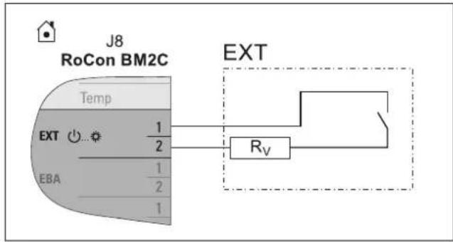
3.7.7 External switching contact
Connecting an external switching contact (" 8-36 EXT switching contact connection" [▶ 24]) enables the operating mode of the indoor unit to be switched over.
The current operating mode is switched by a changing resistance value (" 3-2 Resistance values for evaluating the EXT signal" [▶ 24]). The changeover of the operating mode is only effective for a long as the external switching contact is closed.
The operating mode has an effect on the direct circuit of the indoor unit as well as all other heating circuits connected to this device as an option.
When special functions (e.g. "Manual operation") are activated, the input is not evaluated.
flowchart
graph TD
    A["RoCon BM2C"] --> B["Temp"]
    B --> C["EXT"]
    C --> D["EBA"]
    C --> E["1/2"]
    C --> F["1/2"]
    C --> G["1"]
    H["EXT"] --> I["Rv"]
    I --> J["Ground"]
3-36 EXT switching contact connection
3–2 Resistance values for evaluating the EXT signal
| Operating mode Resistance R _v | Tolerance | |
| Standby | <680Ω | ±5% |
| Heating | 1200Ω | |
| Reduce | 1800Ω | |
| Summer | 2700Ω | |
| Automatic 1 | 4700Ω | |
| Automatic 2 | 8200Ω | |

INFORMATION
The input is not considered for resistance values greater than the value for "Automatic 2".

INFORMATION
The [Heating support (HZU)] function integrated in the RoCon+ HP1 controller (see the controller operating instructions) makes it unnecessary to connect the EXT connection to the burner blocking contact connection of the solar system.
3.7.8 EBA (external requirement request)
By connecting the EBA switching contact to the indoor unit (" 33") and corresponding parametrisation in its RoCon+ HP1 controller, an external switching contact can be used to generate a heat request. If the switching contact is closed, the indoor unit switches to heating operation. The flow temperature is regulated to the temperature set in the [Feed temperature, heating mode] parameter [→ Main menu → Configuration → Heating].
The EBA switching contact has priority over a request from the room thermostat.
The switching contact is not evaluated in cooling operation, standby, manual or summer mode. The heating limits are also ignored.
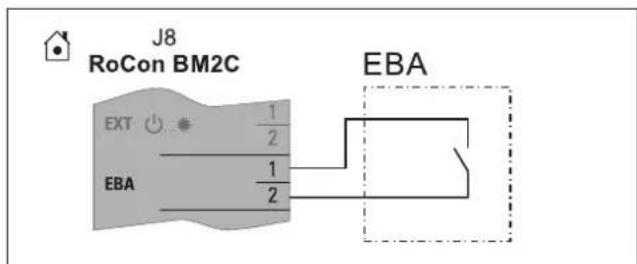
3–37 EBA switching contact connection
3.7.9 Connecting an external heat generator

INFORMATION
To connect an external heat generator, the connection set for external EKBUHSWB heat generators must be installed (see "3.5 Installing optional accessories" [▶ 18]).
For heating support or as an alternative to an electric backup heater, an external heat generator (e.g. gas- or oil-fired boiler) can be connected to the indoor unit. To connect an external heat generator, the connection set for external EKBUHSWB heat generators must be installed (see "3.5 Installing optional accessories" [▶ 18]).
The heat supplied by the external heat generator must be fed to the unpressurised storage tank water in the hot water storage tank of the indoor unit.
Implement the hydraulic connection according to one of the two following options:
- unpressurised via the connections (solar flow and solar return flow) of the hot water storage tank
- for...Biv indoor unit device types, via the integrated pressurised solar heat exchanger.
- Comply with the instructions on hydraulic connections (see "1.2 Safety instructions for installation and operation" [▶5])
- Examples of hydraulic connection (see "Hydraulic connection" in the reference manual for the fitter).
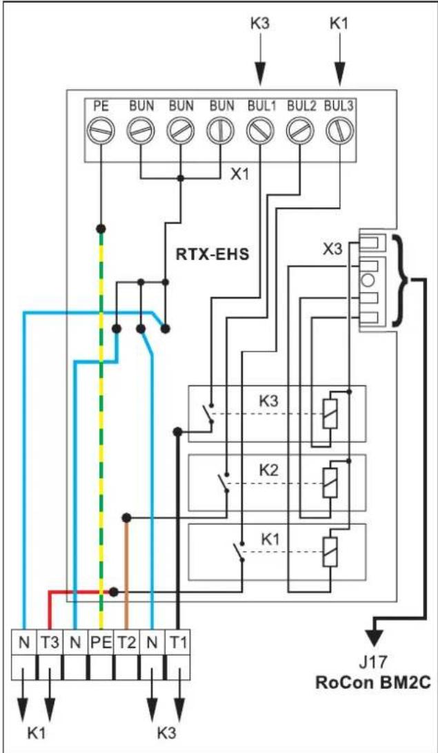
The external heat generator request is connected on PCB RTX-EHS (see "3-38 Connection on the RTX-EHS PCB" [▶ 25]) via a relay. Electrical connection to the indoor unit is possible as follows:
- External heat generator has a potential-free switching contact connection for heat request:
- Connection to K3 if the external heat generator is responsible for the domestic hot water preparation and the backup heating (setting of the [Config. ext. heat source] parameter = DHW + heating support [→ Main menu → Settings → Ext. source])
or
- Connection to K1 and K3 if two external heat generators are used (setting of the [Config. ext. heat source] parameter = Two external heat generators [→ Main menu → Settings → Ext. source]). In this case, K1 connects the external heat generator (e.g. gas-fired or oil-fired boiler) for heating support and K3 connects the external heat generator (EKBUxx) for domestic hot water preparation.
or
- Connection to AUX connection A (see "3.7.13 Connecting switching contacts (AUX outputs)" [▶27])
- External heat generator can only be connected via mains voltage: Connection (\~230 V, maximum load 3000 W) to K1 and K3.

CAUTION
Danger of voltage flash-overs.
- The connections of the RTX-EHS PCB must not be used simultaneously for connecting mains voltage (\~230 V) and SELV ("Safety Extra Low Voltage").
flowchart
graph TD
    A["PE"] --> B["BUN"]
    B --> C["BUN"]
    C --> D["BUN"]
    D --> E["BUL1"]
    E --> F["BUL2"]
    F --> G["BUL3"]
    G --> H["X1"]
    H --> I["RTX-EHS"]
    I --> J["K3"]
    I --> K["K2"]
    I --> L["K1"]
    J --> M["J17 RoCon BM2C"]
    K --> M
    L --> M
    M --> N["N T3 N PE T2 N T1"]
    N --> O["K1"]
    N --> P["K3"]
3-38 Connection on the RTX-EHS PCB
1 Refer to the external heat generator's respective installation instructions for a suitable electrical connection.
2 Installing the connection set for external EKBUHSWB heat generators (see "3.5 Installing optional accessories" [▶ 18]).
3 Make suitable connections on the RTX-EHS PCB of the connection set (see "▲ 3-38 Connection on the RTX-EHS PCB" [▶ 25]).
4 Fix cables that are fed into the connection set from the outside using the strain relief clips and cable ties included (see steps 7 and 8 in "3.7.4 General information on the electrical connection" [▶ 23]).
3.7.10 Connecting the room thermostat

INFORMATION
A separate manual containing instructions about installation and operation is included with this component.
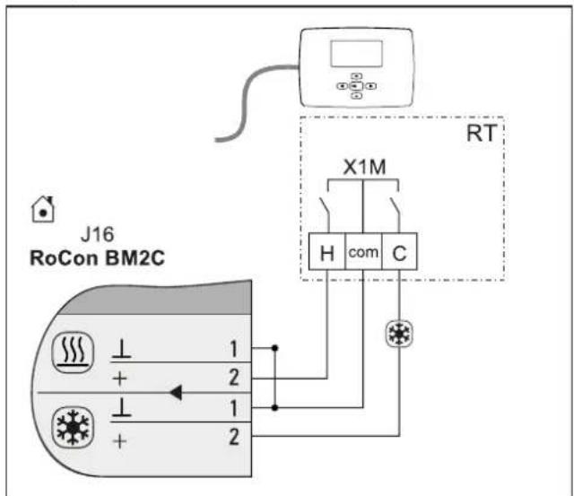
3-39 Connection with wired room thermostat (RT = Daikin EKRTW)
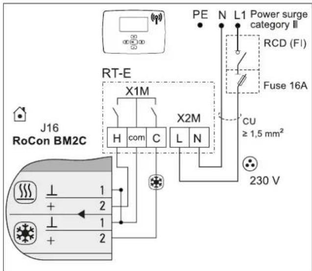
3-40 Connection with radio-controlled room thermostat (RT-E = Daikin EKRTR)
3.7.11 Connection of optional RoCon system components
The optional RoCon devices must be connected to the indoor unit via a 4-wire CAN bus cable (connection J13).
For this, we recommend shielded lines with the following characteristics:
- Standardisation according to ISO 11898, UL/CSA type CMX (UL 444)
- PVC outer sheath with flame retardancy according to IEC 60332-1-2
- Up to 40 m, minimum cross-section 0.75 mm ^2 . Larger conductor cross-section necessary with increasing length.
Commercially available junction boxes can be used to connect CAN bus lines of several RoCon devices.
Ensure that mains, sensor and data bus lines are routed separately. Use only cable ducts with separators or separate cable ducts spaced at least 2 cm apart. Line crossings are permissible.
A maximum of 16 devices with a total line length of up to 800 m can be connected in the entire RoCon system.
EHS157034 room controller
A separate EHS157034 room controller can be connected for each heating circuit to enable remote adjustment of operating modes and room target temperatures from another room.

INFORMATION
Separate installation instructions are included with this component. See the enclosed control system manual for instructions on setting and operation.
EHS157068 mixer module
The EHS157068 mixer module can be connected to the indoor unit (J13 PCB connector) and is controlled by the electronic controller.

INFORMATION
Separate installation instructions are included with this component. See the enclosed control system manual for instructions on setting and operation.
EHS157056 Internet gateway
The controller can be connected to the internet with the optional EHS157056 gateway. This enables remote control of the indoor unit by mobile phones (by app).

INFORMATION
Separate installation instructions are included with this component. See the enclosed control system manual for instructions on setting and operation.
3.7.12 Connecting the HP convector

INFORMATION
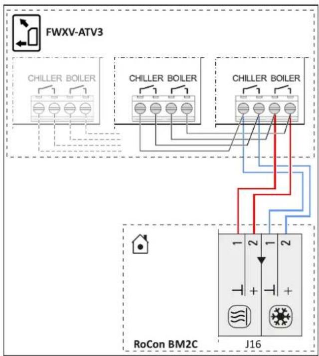
Only the EKRTCTRL1 and EKWHCTRL(0/1) convector controllers can be connected to the indoor unit.

INFORMATION
A separate manual containing instructions about installation and operation is included with this component.

INFORMATION
When changing the operating mode (Heating/Cooling) on a convector, all other convectors must either also be changed or deactivated.
flowchart
graph TD
    A["FWXV-ATV3"] --> B["Chiller Boiler"]
    A --> C["Chiller Boiler"]
    A --> D["Chiller Boiler"]
    B --> E["RoCon BM2C"]
    C --> E
    D --> E
    E --> F["J16"]
    style A fill:#f9f,stroke:#333
    style B fill:#ccf,stroke:#333
    style C fill:#ccf,stroke:#333
    style D fill:#ccf,stroke:#333
    style E fill:#fff,stroke:#333
    style F fill:#fff,stroke:#333
3-41 FWX(V/M)-AATV3 connection
3.7.13 Connecting switching contacts (AUX outputs)
The switching contacts (AUX outputs) can be used for various parametrisable functions.
Switchover contact A-A1-A2 switches under the conditions set in parameter [AUX switching function] [→ Main menu → Settings → Inputs/Outputs] (see controller operating instructions).
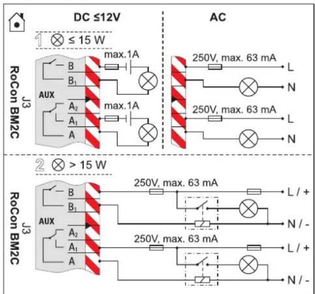
3-42 Connection of switching contact (AUX output)
Connection terminals B+B1 are not occupied for these devices or are available for additional functions.
The contacts in variant 1 (switched power ≤15 W) can be directly integrated as shown in 3-42 Connection of switching contact (AUX output)" [▶ 27].
The relays user for variant 2 (switched output >15 W) must be suitable for a 100 % power-on time.
Switchover contact A-A1-A2 can be used, for example, to control the heat generators in bivalent heating systems consisting of an indoor unit and an oil- or gas boiler. Examples of hydraulic system integration are described in "Hydraulic connection" in the reference manual for the fitter.

INFORMATION
If an A2 F or G-plus condensing boiler is connected, the [AUX switching function] and [AUX wait time] parameters must be set according to the desired function [→ Main menu → Settings → Inputs/Outputs].
See Operating instructions → chapter Parameter settings.
Precise information on the electrical connection and the required parameter settings for such bivalent heating systems are available on the Internet (www.daikin.com) or from your service partner.
3.7.14 Low rate mains connection (HT/NT)
If the outdoor unit is connected to a low rate mains connection, the potential-free switching contact S2S of the receiver, which evaluates the low rate input signal output from the utility company must be connected to plug J8, electricity supply company connection on the RoCon BM2C PCB (see "3-43 T/NT contact connection" [▶ 28]).
When setting the [HT/NT function] parameter >0 [→ Main menu → Settings → Inputs/Outputs], certain system components are switched off during peak periods (see controller operating instructions).
The following types of low rate mains connection are common:
- Type 1: With this type of low rate mains connection, the power supply to the heat pump outdoor unit is not interrupted.
- Type 2: With this type of low rate mains connection, the power supply to the heat pump outdoor unit is interrupted after a certain period of time.
- Type 3: With this type of low rate mains connection, the power supply to the heat pump outdoor unit is interrupted immediately.
Potential-free switching contact S2S can be implemented as a normally closed or normally open switching contact.
- If implemented as a normally closed switching contact, the [HT/NT contact] parameter=1 must be set [→ Main menu → Settings → Inputs/Outputs]. When the EVU sends the off-peak signal, switching contact S2S is opened. The system switches to "Mandatory OFF". If the signal is sent again, potential-free switching contact S2S closes and the system resumes operation.
- If implemented as a normally open switching contact, the [HT/NT contact] parameter=0 must be set [→ Main menu → Settings → Inputs/Outputs]. When the EVU sends the off-peak signal, switching contact S2S is closed. The system switches to "Mandatory OFF". If the signal is sent again, potential-free switching contact S2S opens and the system resumes operation.
[HT/NT contact] = 1 [HT/NT contact] = 0
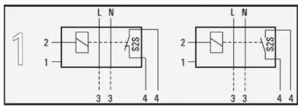
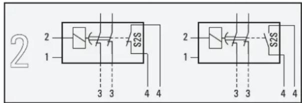
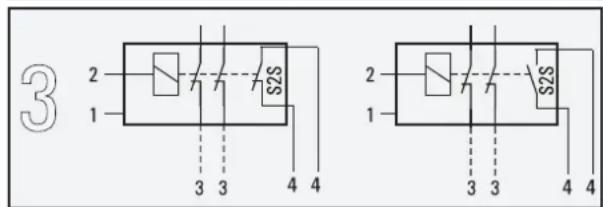
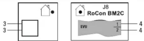
3-43 HT/NT contact connection
1 Mains connection box for low rate mains connection
2 Receiver for evaluating the HT/NT control signal
3 Power supply of the heat pump outdoor unit (see respective installation manual for the heat pump outdoor unit)
4 Potential-free switching contact for heat pump indoor unit
3.7.15 Connecting an intelligent controller (Smart Grid - SG)
If the [Smart grid] parameter=1, the function [ Main menu Settings Inputs/Outputs] is activated (see controller operating instructions), the heat pump is switched to normal or a mode with higher temperatures depending on the utility company signal.
For this purpose, the SG1/SG2 floating switching contacts of the intelligent controller must be connected to the J8 connector, Smart Grid and electricity supply company connections on the RoCon BM2C PCB (see "3-44 Connecting the Smart Grid" [▶ 28]).
As soon as the Smart Grid function is active, the HT/NT function is automatically deactivated. Smart grid mode The heat pump is operated differently depending on the value of the parameter [ Main menu Settings Inputs/Outputs] (see controller operating instructions).
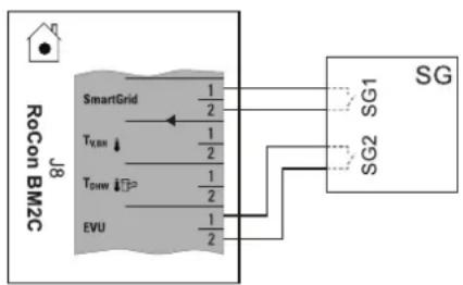
flowchart
graph TD
    A["RoCon BM2C"] --> B["SmartGrid"]
    B --> C["T_LBM"]
    B --> D["T_DSW"]
    B --> E["EVU"]
    C --> F["1/2"]
    D --> G["1/2"]
    E --> H["1/2"]
    F --> I["SG1"]
    G --> J["SG2"]
    H --> K["SG"]
3-44 Connecting the Smart Grid
3.8 Connection for refrigerant

INFORMATION
Follow the installation instructions for the outdoor unit.
3.8.1 Laying refrigerant piping

CAUTION
The use of refrigerant piping that has already been used may lead to damage to the unit.
- Do not reuse refrigerant piping that has been used with another refrigerant. Replace or carefully clean the refrigerant piping.
- Install lines with bending unit and an adequate clearance to electrical lines.
- Only solder with light nitrogen flow (hard soldering only).
- Do not apply thermal insulation to connection points until after commissioning (for purposes of leakage search).
- Make flared connections and connect to the devices (observe tightening torque, see "6.3 Tightening torques" [▶ 34]).
3.8.2 Pressure test and filling the refrigerant circuit

WARNING
The overall heat pump system contains refrigerants with fluorinated greenhouse gases that are harmful to the environment when released.
Refrigerant type: R32
GWP* value: 675
*GWP = Global Warming Potential
- Enter the total filling quantity of refrigerant on the label supplied on the external heat pump unit (for notes, see Installation instructions for the heat pump outdoor unit).
- Never allow refrigerant to escape into the atmosphere - always extract and recycle with a suitable recycling device.
1 Perform pressure test with nitrogen.
- Use nitrogen 4.0 or higher.
- Maximum 40 bar.
2 After the leak search is complete, completely drain.
3 Vacuum lines.
- Pressure to be reached: 1 mbar absolute.
- Time: Minimum 1 h
4 Check whether additional refrigerant is needed for primer filling; fill if necessary.
5 Open the stop valves on the outdoor unit completely until the stop. Slightly tighten.
6 Reinstall the valve caps.
7 Check that the storage tank temperature sensors are inserted to a depth of t_DHW1 80 cm and t_DHW2 60 cm.
3.9 Filling the system
Only fill the indoor unit after all installation work is completed in the order shown below.
3.9.1 Checking the water quality and adjusting the manometer
1 Comply with the instructions for the water connection (see "3.6 Water connection" [▶ 19]) and for the water quality.
2 Adjust the mechanical manometer (mounted on site in accordance with "3.6.2 Connecting hydraulic lines" [▶ 19] or temporarily installed with filling hose): Turn the pressure gauge glass so that the minimum pressure marking corresponds to the system height +2 m (1 m water column corresponds to 0.1 bar).
3.9.2 Filling hot water heat exchangers
1 Open the shut-off valve for the cold water supply pipe.
2 Open the hot water tap connections so that the draw-off volume can be set as high as possible.
3 Once water has been discharged from the tap connections, do not interrupt the cold water flow to ensure that the heat exchanger will be fully vented and that any impurities or residue will be discharged.
3.9.3 Filling the storage tank
Without installed solar system
1 Connect the charge hose with non-return valve (1/2") to the "Solar flow" connection (item a).
2 Fill the storage tank of the indoor unit until water emerges at the overflow connection (item b).
3 Disconnect the charge hose with backflow prevention (1/2") again.
With installed solar system
1 Install the filling connection with combined filling and draining valve (accessory combined filling and draining BA) following the solar control and pump unit (EKSRPS4).
2 Connect the charge hose with non-return valve (1/2") to the previously installed combined filling and draining valve.
3 Fill the storage tank of the indoor unit until water emerges at the overflow connection (item b).
4 Disconnect the charge hose with backflow prevention (1/2") again.
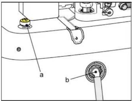
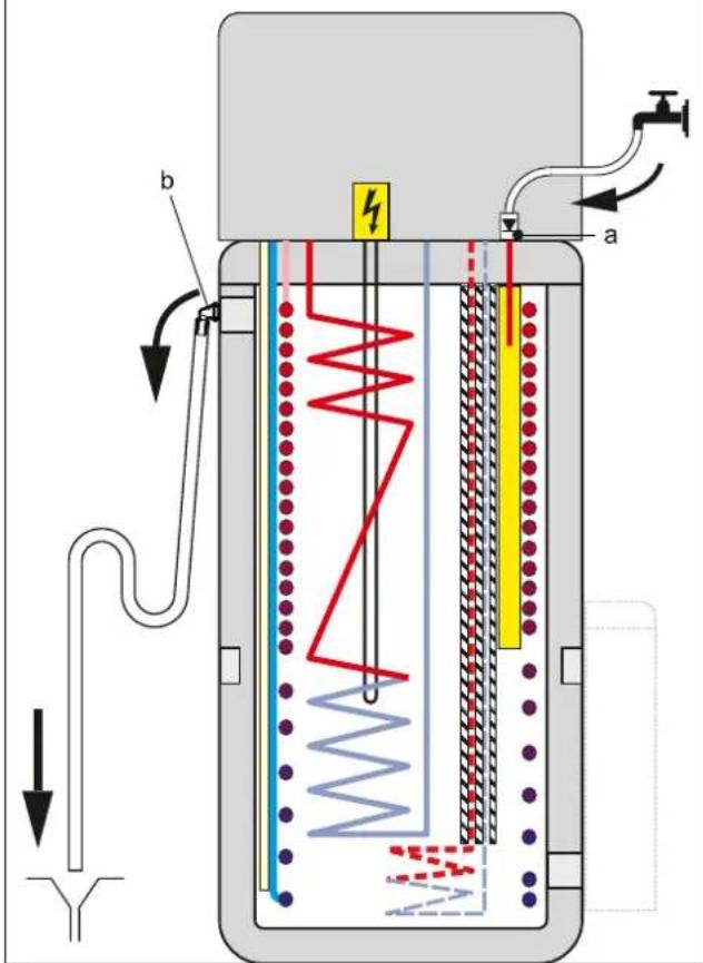
3-45 Filling the buffer tank - without connected DrainBack solar system
a p=0 Solar flow
b Safety overflow
3.9.4 Filling the heating system

DANGER: RISK OF ELECTROCUTION
During the filling process, water may escape from any leaking points that can cause an electric shock if it comes into contact with live parts.
- Before the filling process, de-energise the indoor unit.
- After the first filling and before switching on the indoor unit at the mains switch, check that all electric parts and connection points are dry.

INFORMATION
Comply with the instructions for the water connection (see "3.6 Water connection" [▶ 19]) and water quality (see "1.2.6 Heating system and sanitary connection" [▶ 7]).
4 Configuration
1 Connect the charge hose (item a) with the non-return valve (1/2") and an external manometer (field supply) to the combined filling and draining valve (item b) and secure it against slipping off with a hose clamp.
2 Connect the drain hose to the air purge valve, and route it away from the device. Open the air purge valve with the hose connected; check to make sure that the other air purge valve is closed.
3 Open the water tap (item d) on the feed pipe.
4 Open the combined filling and draining valve (item b) and monitor the manometer.
5 Fill the system with water until the external manometer shows that the system target pressure is reached (system height +2 m; 1 m water column = 0.1 bar). The overpressure valve must not actuate!
6 Close the manual air purge valve as soon as water emerges free of bubbles.
7 Close the water tap (item d). The combined filling and draining valve must remain open in order to read off the water pressure on the external manometer.
8 Switch on the power supply of the indoor unit.
9 In the RoCon+ HP1 controller in the "Operating mode" menu, select the "Heating" operating mode [→ Main menu → Operating mode].
- After the start phase, the indoor unit runs in hot water heating operation.
10 Constantly check the water pressure on the external manometer during hot water heating mode, and top up water via the combined filling and draining valve (item b) if necessary.
11 Vent the entire heating system as described in "5.3 Bleeding the hydraulic system" [▶ 31] (open the system's control valves. At the same time, the underfloor heating system can be filled and flushed by the underfloor distributor.
12 Again check the water pressure on the external manometer, and top up water via the combined filling and draining valve (item b) if necessary.
13 Remove the charge hose (item a) with backflow preventer from the combined filling and draining valve (item b).
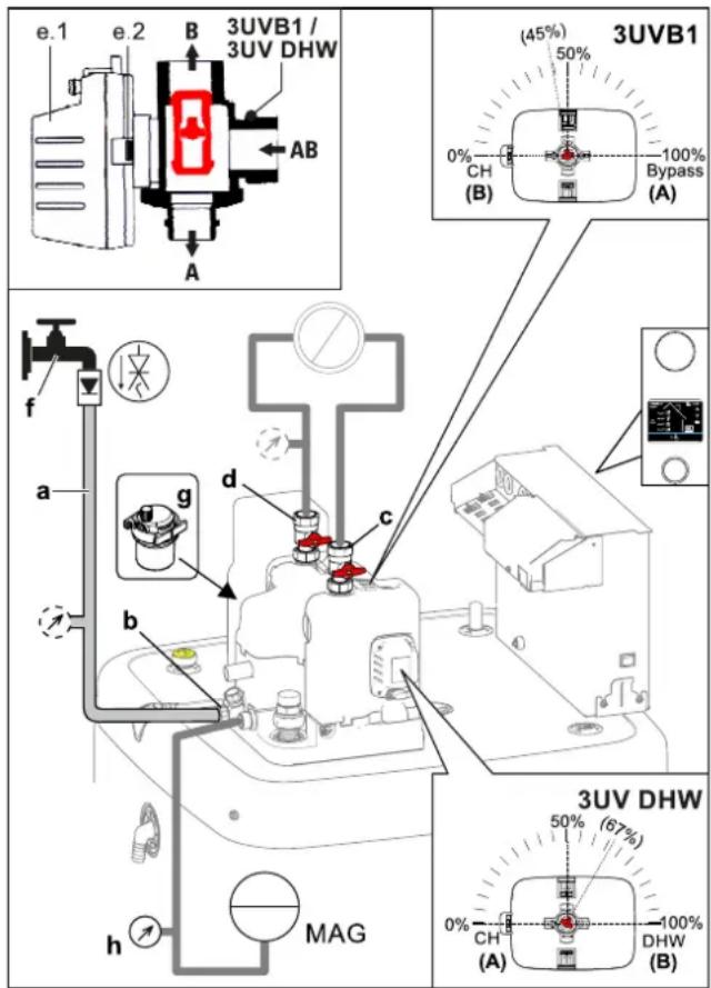
3–46 Filling the heating circuit
a Charge hose with non-return valve (and manometer ^(1) )
b Combined filling and draining valve
c Heater ball valve – flow
d Heater ball valve – return flow
e.1 Valve drive
e.2 Unlocking key of the drive lock
f Water tap
g Automatic vent valve
h Manometer
3UV DHW 3-way valve (distribution valve, hot water/heating/heating support)
3UVB1 3-way valve (mixing valve)
MAG Expansion vessel (field supply)
4 Configuration
If the system is not configured correctly, it may not work as expected.
The system is configured via the control panel of the controller. Please refer to the operating instructions.
If necessary, the configuration of optional components (such as the room thermostat or the solar system) must be carried out according to the respective instructions.
5 Check list for start-up

INFORMATION
Read chapter "General safety precautions" thoroughly before carrying out the steps described here.

INFORMATION
If the outdoor unit has been disconnected from the power supply for an extended period of time or the indoor unit was operated before the outdoor unit for an extended period of time, the indoor unit must be restarted to establish communication between the units. Without communication, the outdoor unit is not used to generate heat.
5.1 Requirements
- The indoor unit is fully connected.
- The refrigerant system is dehumidified and filled with the specified amount of refrigerant.
- The heating and hot water system has been filled and pressurised to the correct pressure (see "3.9.4 Filling the heating system" [▶ 29]).
- The storage tank is filled up to the overflow (see "3.9.3 Filling the storage tank" [▶ 29]).
- Optional accessories have been installed and connected up.
- The heating system's control valves are open.
5.2 Commissioning at low ambient temperatures
At low ambient temperatures, the safety settings of the indoor unit may prevent heat pump operation. In such cases, an external heat generator is required to temporarily raise both the storage and return temperatures of the heating network.
Minimum storage temperatures for heat pump operation:
Ambient temperature < -2^:30^
Ambient temperature < 12^:23^
The following steps must be performed:
With electrical backup heater:
1 Parameter [Heating support (HZU)]: "On" select [→ Main menu → Settings → ISM]
2 Parameter [Config. ext. heat source]: "Backup heater BUH" select [→ Main menu → Settings → Ext. source]
3 Parameter [External power hot water]: Select maximum output of backup heater [→ Main menu → Settings → Ext. source]
4 Parameter [1 x hot water]: "On" select [→ Main menu → User → 1x load]
Without electrical backup heater:
1 Parameter [Heating support (HZU)]: "On" select [→ Main menu → Settings → ISM]
2 The storage water must be heated to the required minimum temperature by an external heat generator.
5.3 Bleeding the hydraulic system
1 Make sure that the automatic vent valve cap is open (item a).
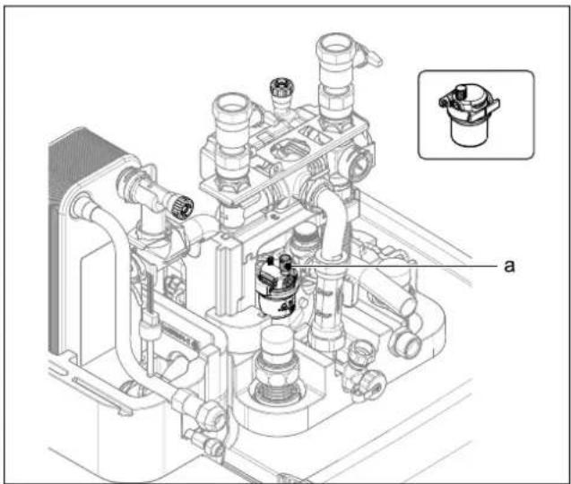
natural_image
Technical line drawing of a mechanical assembly with pipes and housing, showing internal components and a small inset view labeled 'a' (no text or symbols beyond label)5-1 Automatic vent valve
a Automatic vent valve cap
2 Provide the manual air purge valve (item a) with a hose and direct it away from the unit. Open the valve until air no longer comes out.
3 Fit the second manual air purge valve (item b) with a hose and open until no more air escapes.
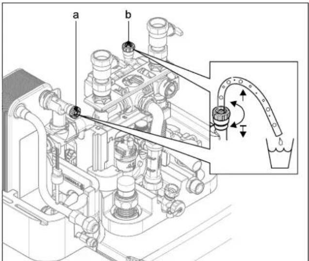
5-2 Manual air purge valves
a Manual air purge valve
b Second manual air purge valve
4 Activating the ventilation function (see operating instructions RoCon+ HP1).
By activating the ventilation function, the RoCon+ HP1 controller starts a permanently defined sequence program with start/stop operation of the integrated heating circulation pump and various settings of the 3-way changeover valves integrated in the indoor unit.
Air present in the hydraulics and the connected heating circuits can escape via the automatic air purge valve during the venting function.

INFORMATION
The activation of this function does not replace correct venting of the heating circuit.
The heating circuit must be completely full before activating this function.
5 Check list for start-up
5 Check the water pressure and replenish water if necessary (see "3.9.4 Filling the heating system" [▶ 29]).
6 Repeat the air purge, checking and replenishing process until:
- It is completely vented.
- There is sufficient water pressure.
5.4 Checking the minimum flow
The minimum flow must be checked with the heating circuit closed.

INFORMATION
If the minimum flow is too low, an error message may appear and the heating system may shut down.
If the minimum flow rate is not sufficient, there may be air in the circulation pump or the valve drive of the 3-way changeover valves (3UVB1/3UV DHW) is defective.
- Vent the circulation pump.
- Check the function of the valve drives; replace the valve drive if necessary.
1 Close the valves and adjuster drives of all connected heat distribution circuits.
2 Set operating mode "Heating" on the indoor unit controller [→ Main menu → Operating mode].
3 Read information parameters [Volume flow] [→ Main menu → Information → Values].
- The flow rate must be at least 480 l/h (see Controller operating instructions).

INFORMATION
The controller of the indoor unit constantly monitors the flow rate of the internal heat generator circuit. Different minimum flow rate values are required depending on the active operating mode:
"Heating" operating mode: 480 l/h
"Cooling" operating mode: 660 l/h
Automatic thawing function (Defrost) active: 780 l/h
If an error message regarding an inadequate minimum flow is displayed at a flow rate of more than 480 l/h, check the actual flow rate in the active operating mode and eliminate possible fault causes.
5.5 Start screed drying (only if required)
In the screed program, the flow temperature is controlled according to a pre-set temperature profile.
See the Controller operating instructions for further information on the screed program, its activation and sequence.
After the screed program has ended, the RoCon+ HP1 controller continues to work in the previously set operating mode.
5.6 Commissioning checklist
| Commissioning checklist/Check off measures carried out | Chapter | |||
| 1. | Supply indoor unit and outdoor unit (if present) with voltage | These instructions | "3.7 Electrical connection" [▶ 20] | |
| 2. Enter "Expert code" RoCon+ HP1 4.5.1 | ||||
| 3. Set the operating parameters[→ Configuration Wizard → Setting parameters][Hot water temperature target 1]· Do not set below 40°C during commissioning.· Never set below 35°C after commissioning! | RoCon+ HP1 5.2 | |||
| 4. Activate the ventilation function | RoCon+ HP1 4.5.7 | |||
| · Check the water pressure | These instructions "5.3 Bleeding the hydraulic system" [▶ 31] | |||
| · Checking the minimum flow | "5.4 Checking the minimum flow" [▶ 32] | |||
| 5. Activate the "Heating" operating modeObserve the waiting time (up to 5 min)Observe "5.2 Commissioning at low ambient temperatures" [▶ 31] at low ambient temperatures. | RoCon+ HP1 4.1 | |||
| 6. | Start-up is complete when the display shows the WW temperature above 40°C. | |||
| 7. [Screed drying] (if necessary)Screed drying only after commissioning is complete. As soon as the temperature of the storage tank is at least 40°C, activate (also possible without outdoor unit). | RoCon+ HP1 4.5.7 | |||
5.7 Handover to the operating company
Once the test run is finished and the unit operates properly, please make sure the following is clear for the user:
- Fill in the installer setting table (in the operation manual) with the actual settings.
- Make sure that the user has the printed documentation and ask him/her to keep it for future reference. Inform the user that he can find the complete documentation on the url as earlier described in this manual.
- Explain the user how to properly operate the system and what he/she has to do in case of problems.
- Show the user what he/she has to do in relation to maintaining the unit.
- Explain the user about energy saving tips as described in the operation manual.
6 Technical data
Part of the current technical data is available on the regional Daikin-website (publicly accessible). The complete technical data is available via the Daikin Business Portal (authentication required).
6.1 Information on the type plate
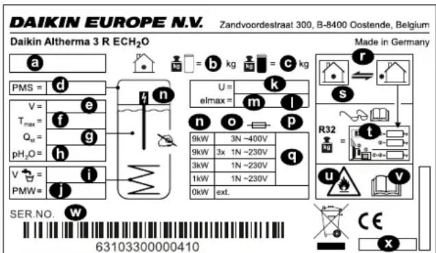
6–1 Type plate
a Device type
b Empty weight
c Total filled weight
d Max. permissible operating pressure PMS (heating)
e Total storage capacity
f Max. permissible operating temperature T max
g Standby heat loss in 24 hours at 60°C (storage tank) Q
h Operating pressure of storage water pH _2 O
i Nominal capacity of drinking water
j Max. operating pressure PMW (plumbing)
k Nominal voltage U
I Protection type
m Electrical power input elmax
n Backup heater (optional)
o Backup heater protection class (optional)
p Backup heater fuse (optional)
q Output/backup heater power supply (optional)
To select; 0 kW: no/external heat source
r Refrigerant circuit
s Max. operating pressure (refrigerant circuit)
t Total refrigerant charge (for information, see installation instructions for the outdoor heat pump unit)
u Attention: Flammable refrigerant
v Further information on the refrigerant: See instructions
w Serial number (specify in the event of complaints or inquiries)
x Date of production
6.2 Characteristic lines
6.2.1 Sensor characteristic lines
6–1 Temperature sensor
| Measured temperature in °C | ||||||||||||||||
| -20 -10 0 10 20 30 40 50 60 70 80 90 100 110 120 | ||||||||||||||||
| Sensor resistance in kOhm according to standard or manufacturer's indications | ||||||||||||||||
| t_DHW1, t_V,BH | NTC | 98.66 | 56.25 | 33.21 | 20.24 | 12.71 | 8.20 | 5.42 | 3.66 | 2.53 | 1.78 | 1.28 | 0.93 | 0.69 | 0.52 | 0.36 |
| t_R, t_V, t_DHW2, t_DC | NTC | - | - | 65.61 | 39.9 | 25 | 16.09 | 10.62 | 7.176 | 4.96 | 3.497 | 2.512 | 1.838 | 1.369 | - | - |
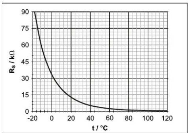
line
| t / °C | Rs / kΩ | | ------ | ------- | | -20 | 90 | | 0 | 30 | | 20 | 15 | | 40 | 5 | | 60 | 2 | | 80 | 1 | | 100 | 0.5 | | 120 | 0 |6-2 Characteristic of temperature sensor t_DHW1 , t_V,BH
R_s Sensor resistance (NTC)
t Temperature
t_DHW1 Storage tank temperature sensor
t_v,BH Backup heater flow temperature sensor
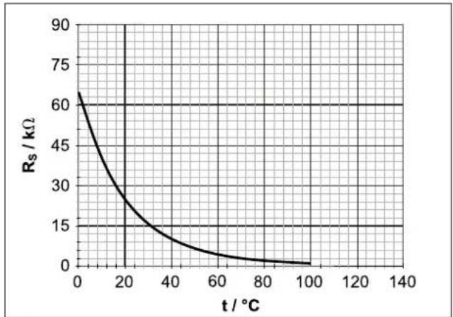
line
| t / °C | Rs / kΩ | | ------ | ------- | | 0 | 60 | | 20 | 30 | | 40 | 15 | | 60 | 5 | | 80 | 2 | | 100 | 1 |6-3 Characteristic of temperature sensor t_R, t_V, t_DHW2, t_DC
R_s Sensor resistance (NTC)
t Temperature
t_pc Temperature sensor liquid line (refrigerant)
t_DHW2 Storage tank temperature sensor 2
t_R Return temperature sensor
t_v Flow temperature sensor
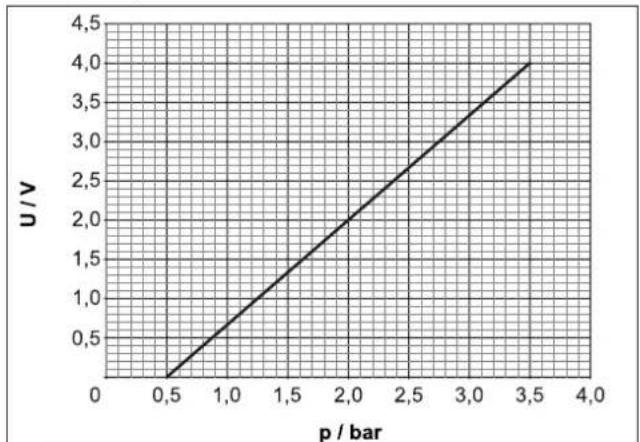
line
| p / bar | U / V | | ------- | ----- | | 0.5 | 0.5 | | 1.0 | 1.0 | | 1.5 | 1.5 | | 2.0 | 2.0 | | 2.5 | 2.5 | | 3.0 | 3.0 | | 3.5 | 3.5 | | 4.0 | 4.0 |6-4 Characteristic of the pressure sensor (DS)
p Water pressure
U Voltage
6.2.2 Characteristic curves for pumps
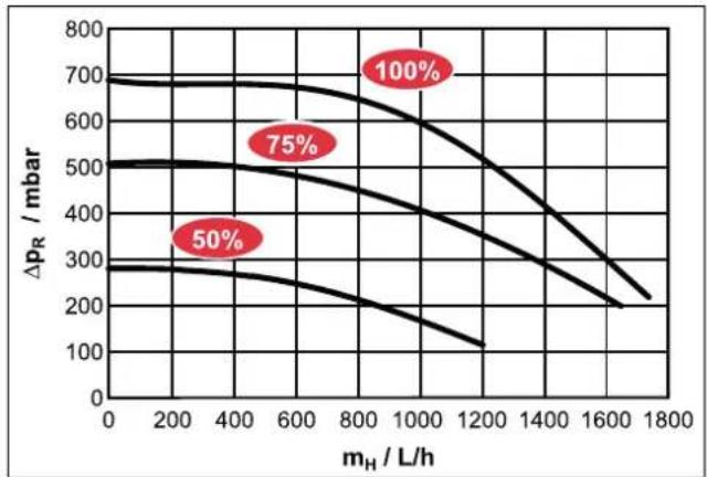
line
| m_H / L/h | Δp_R / mbar (50%) | Δp_R / mbar (75%) | Δp_R / mbar (100%) | | --------- | ----------------- | ----------------- | ------------------ | | 0 | 300 | 500 | 700 | | 200 | 280 | 480 | 680 | | 400 | 260 | 460 | 660 | | 600 | 240 | 440 | 640 | | 800 | 220 | 420 | 620 | | 1000 | 200 | 400 | 600 | | 1200 | 180 | 380 | 580 | | 1400 | 160 | 360 | 560 | | 1600 | 140 | 340 | 540 | | 1800 | 120 | 320 | 520 |6-5 Residual head of the internal heating circulation pump
p_R Residual head of internal heating circulation pump
m_H Flow rate of heating system
6.3 Tightening torques

6-2 Tightening torques
| Component Thread size | Tightening | torque in Nm |
| Temperature sensor all Max. 10 | ||
| Hydraulic line connections (water) | 1" 25 – 30 | |
| Gas line connections (refrigerant) | 5/8" 63 – 75 | |
| Fluid line connections (refrigerant) | 1/4" 15 – 17 | |
| Fluid line connections (refrigerant) | 3/8" 33 – 40 | |
| Backup heater 1.5" Max. 10 | (handtight) |
6.4 Minimum floor area and ventilation openings

CAUTION
The use of refrigerant piping that has already been used can lead to damage to the unit.
- Do not reuse refrigerant piping that has been used with another refrigerant. Replace or carefully clean the refrigerant piping.
- If the total refrigerant charge in the system is < 1.84 ~kg , there are no further requirements.
- If the total refrigerant charge in the system is ≥ 1.84 kg, other minimum floor space requirements must be met:
1 Compare the total refrigerant charge in the system (m e ) with the maximum refrigerant filling (m max ) permitted for the installation room (A _room ), (see " 6–3 Maximum refrigerant filling permitted in a room" [▶ 35]).
- If m_c ≤ m_ : The device can be installed in this room without any further requirements.
- If m_c > m_ : Proceed with the following steps.
2 Compare the minimum floor area ( A_min ) from with the floor area of the installation room ( A_nom ) and the adjacent room ( A_nom2 ) (see "6-4 Minimum floor area of indoor unit" [▶35]).
- If A_ ≤ A_room + A_room2 : Proceed with the following steps.
- If A_ > A_room + A_room2 : Contact your local dealer.
3 Calculate coolant quantity (dm): dm=1.9-m_max(m_max from "6-3 Maximum refrigerant filling permitted in a room" [▶ 35] the A_room for the given size of the installation room)
4 For calculated dm, take the "6-5 Minimum area of the ventilation opening" [▶ 35] minimum area of the ventilation opening (VA _min ) for natural ventilation between the installation room and the adjacent room.
5 The device can be installed if:
- 2 ventilation openings are provided between the installation room and adjacent room (1 each at top and bottom)
- Bottom opening: The bottom opening must meet the requirements for the minimum area of the ventilation opening (VA min ). It must be as close to the ground as possible. If the ventilation opening starts on the floor, the height ≥ must be 20 mm. The bottom of the opening must be ≤ 100 mm above the floor. At least 50% of the required minimum area of the ventilation opening (VA min ) must be <200 mm from the ground. The entire area of the opening must be <300 mm from the floor.
- Upper opening: The area of the upper opening must be larger or the same size as the lower opening. The bottom of the upper opening must be at least 1.5 m above the top edge of the lower opening.
- Ventilation openings to the outside are not considered suitable ventilation openings.
6–3 Maximum refrigerant filling permitted in a room
| A_room (m^2) Maximum refrigerant filling permitted in a room ( m_max ) (kg) | |
| 1 0.14* | |
| 2 0.28* | |
| 3 0.41* | |
| 4 0.55* | |
| 5 0.69* | |
| 6 0.83* | |
| 7 0.90* | |
| 8 0.97* | |
| 9 1.02* | |
| 10 1.08* | |
| 11 1.13* | |
| 12 1.18* | |
| 13 1.23* | |
| 14 1.28* | |
| 15 1.32* | |
| 16 1.37* | |
| 17 1.41* | |
| 18 1.45* | |
| 19 1.49* | |
| 20 1.53* | |
| 21 1.56* | |
| 22 1.60* | |
| 23 1.64* | |
| 24 1.67* | |
| 25 1.71* | |
| 26 1.74* | |
| 27 1.77* | |
| A_room (m2) Maximum refrigerant filling permitted in a room (mmax) (kg) | |
| 28 1.81* | |
| 29 1.84 | |
| 30 1.87 | |
| 31 1.90 | |
- * Values are only required for step 3 (calculation of dm).
6-4 Minimum floor area of indoor unit
| m_c(kg) | Minimum floor area A_(m^2) |
| 1.84 | 28.81 |
| 1.86 | 29.44 |
| 1.88 | 30.08 |
| 1.90 | 30.72 |
6–5 Minimum area of the ventilation opening
| dm (kg) | Minimum area of the ventilation opening (VA_) ( cm^2 ) |
| 1.76 | 716 |
| 1.63 | 662 |
| 1.49 | 605 |
| 1.35 | 549 |
| 1.21 | 493 |
| 1.07 | 437 |
| 1.00 | 419 |
| 0.93 | 406 |
| 0.88 | 392 |
| 0.82 | 377 |
| 0.77 | 362 |
| 0.72 | 345 |
| 0.67 | 328 |
| 0.62 | 312 |
| 0.58 | 294 |
| 0.53 | 276 |
| 0.49 | 258 |
| 0.45 | 241 |
| 0.41 | 223 |
| 0.37 | 204 |
| 0.34 | 186 |
| 0.30 | 168 |
| 0.26 | 149 |
| 0.23 | 131 |
| 0.19 | 112 |
| 0.16 93 | |
| 0.13 75 | |
| 0.09 56 | |
| 0.06 38 | |
| 0.03 19 |
Example: Total refrigerant charge 1.84 kg, installation room 15 m²
6 From "☐ 6-3 Maximum refrigerant filling permitted in a room" [▶ 35]: m=1.84 kg, A _min = 29 m ^2
Result: Requirement for minimum room size NOT fulfilled, ventilation opening required
7 Check with "6-4 Minimum floor area of indoor unit" [▶ 35]: A_room (installation room) + A_room2 (adjacent room) ≥ A_min ? If so, continue:
8 From " 6-3 Maximum refrigerant filling permitted in a room" [▶ 35]: A_bm = 15 m^2 m_max = 1.32 kg
9 dm=1.9 kg-1.32 kg=0.58 kg
10 From "6-5 Minimum area of the ventilation opening" [▶ 35]: dm=0.58 kg → VA _min =294 cm ^2
6.5 Electrical connection diagram
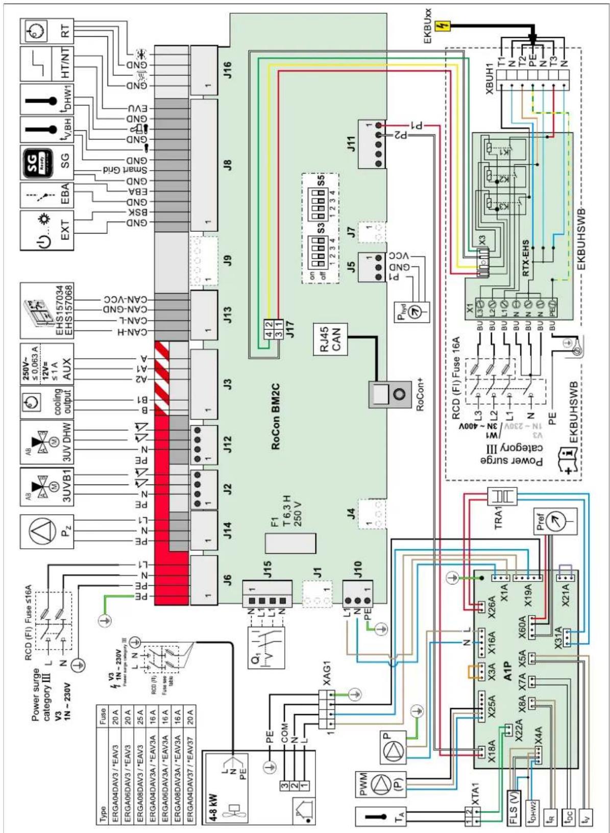
6-6 Electrical connection diagram
6–6 Key names for connection and wiring diagrams
| Item Name Item Name | |||
| Heat pump outdoor unit J2 Plug connection 3UVB1 | |||
| Heat pump indoor unit J3 Plug connection AUX switching contacts and cooling output status output | |||
| 3UVB1 3-way changeover valve (internal heat generator circuit) | J5 Pressure sensor plug connection | ||
| 3UV DHW 3-way changeover valve (hot water/heating) J6 Plug connection mains voltage | |||
| a Switch box J3 Plug connection for EXT | Smart Grid EVU Plug connection | Plug connection for storage tank temperature sensor t_DHW1 | |
| A1P Printed PCB (heat pump basic control) Plug connection for EBA | |||
| AUX Switching contact outputs (A-A1-A2) + (B-B1) Plug connection for U switching contacts | |||
| b Switch box cover Backup heater infeed temperature sensor plug | connection t_V,BH | ||
| cooling output Status output for "Cooling" operating mode floor heating control connection cooling output) | |||
| DS Pressure sensor | |||
| EBA | Switching contact for external requirement request | J10 | Plug connection for internal wiring to X1A |
| EHS157034 | Room station | J11 | Plug connection for internal wiring to X18A (A1P) |
| EHS157068 | Mixer module | J12 | Plug connection 3UV DHW |
| EKBUxx | Backup heater | J13 | System bus plug connection (e.g. room station) |
| EXT | Switching contact for external operating mode changeover | J14 | Circulation pump P_Z plug connection |
| F1 | Fuse 250 V T 2 A (RoCon BM2C) | J15 | Mains switch plug connection |
| FLS | FlowSensor | J16 | Room thermostat (EKRTR/EKRTW) plug connection |
| HT/NT | Switching contact for low rate mains connection | K1 | Relay 1 for backup heater |
| P | Heating circulation pump (connected inside the device) | K2 | Relay 2 for backup heater |
| P_Z | Circulation pump | K3 | Relay 3 for backup heater |
| PWM | Pump connection (PWM signal) | X1 | Terminal strip for backup heater mains connection |
| RJ45 CAN | Internal wiring plug connection (RoCon BM2C) (to RoCon+ B1) | X3 | Internal wiring plug connection to J17 (RoCon BM2C) |
| RoCon BM2C | Printed PCB (basic controller module) | X1A | Plug connection to J10 from RoCon BM2C |
| RoCon+ B1 | Controller control panel X3A Plug connection for internal wiring (bridging plug) | ||
| RT Room thermostat (EKRTW) X4A Plug connection for F L S flow sensor and t DHW2 | |||
| RT-E | Receiver for wireless room thermostat (EKRTR) | X5A | Plug connection for t_V flow temperature sensor |
| RTX-EHS | Printed PCB (backup heater) | X7A | Plug connection for temperature sensor (refrigerant fluid) t_DC |
| SG | Switching contact for Smart Grid (intelligent mains connection) | X8A Plug connection for return temperature sensor t R | |
| T_A | Outdoor temperature sensor | X16A | Plug connection for heating circulation pump |
| TRA1 | Transformer | X18A | Plug connection to J11 from RoCon BM2C |
| t_DHW1 | Storage tank temperature sensor 1 (RoCon BM2C) | X19A | Plug connection to XAG1 |
| t_DHW2 | Storage tank temperature sensor 2 (A1P) | X21A | Plug connection for internal wiring (bridging plug) |
| t_R | Return temperature sensor (A1P) | X22A | Plug connection for XTA1 |
| t_V | Flow temperature sensor (A1P) | X26A | Plug connection to TRA1 (230 V) |
| t_V,BH | Backup heater flow temperature sensor | X31A | Plug connection to TRA1 (12 V) |
| X2M6 | HPc-VK-1 connection cable clamp | ||
| X2M7 | HPc-VK-1 connection cable clamp | ||
| X11M | Terminal strip in FWXV-ATV3 | ||
| XAG1 | Heat pump outdoor unit plug connection | ||
| XBUH1 | Backup heater plug connection (EKBUxx) | ||
| XAG1 | Heat pump outdoor unit plug connection | ||
| XTA1 | Outdoor temperature sensor terminal strip T_A | ||
6.6 Piping diagram for refrigerant circuit
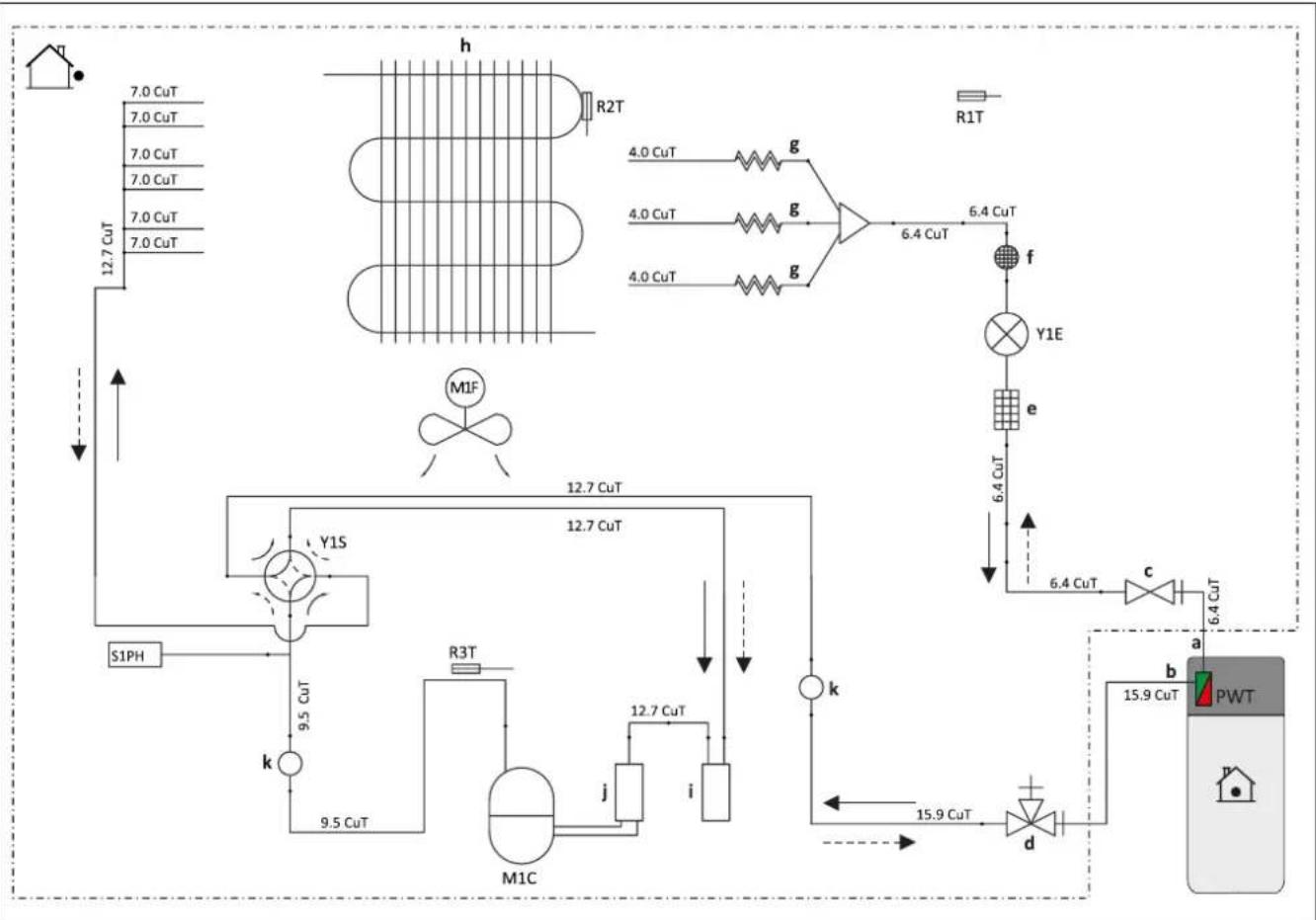
flowchart
graph TD
    A["7.0 CuT"] --> B["12.7 CuT"]
    C["7.0 CuT"] --> B
    D["7.0 CuT"] --> B
    E["7.0 CuT"] --> B
    F["7.0 CuT"] --> B
    G["R2T"] --> H["g"]
    I["R1T"] --> J["f"]
    K["4.0 CuT"] --> L["g"]
    M["4.0 CuT"] --> L
    N["4.0 CuT"] --> L
    O["4.0 CuT"] --> P["g"]
    Q["6.4 CuT"] --> R["Y1E"]
    S["6.4 CuT"] --> T["e"]
    U["6.4 CuT"] --> V["c"]
    W["6.4 CuT"] --> X["a"]
    Y["15.9 CuT"] --> Z["b"]
    AA["PWT"] --> AB["d"]
    AC["MIF"] --> AD["k"]
    AE["S1PH"] --> AF["k"]
    AG["12.7 CuT"] --> AH["M1C"]
    AI["12.7 CuT"] --> AJ["9.5 CuT"]
    AK["R3T"] --> AL["j"]
    AM["12.7 CuT"] --> AN["i"]
    AO["15.9 CuT"] --> AP["d"]
    AQ["6.4 CuT"] --> AR["e"]
    AS["6.4 CuT"] --> AT["f"]
    AU["15.9 CuT"] --> AV["d"]
6-7 Components in the heat pump circuit
a Field piping (liquid: ∅6.4 mm flare connection)
b Field piping (liquid: ∅15.9 mm flare connection)
c Stop valve (liquid)
d Stop valve with service port (gas)
e Filter
f Muffler with filter
g Capillary tube
h Heat exchanger
i Accumulator
J Compressor accumulator
k Muffler
M1C Compressor
M1F Fan
PWT Plate heat exchanger
R1T Thermistor (outdoor air)
R2T Thermistor (heat exchanger)
R3T Thermistor (compressor discharge)
S1PH High pressure switch (automatic reset)
Y1E Electronic expansion valve
Y1S Solenoid valve (4-way valve)(ON: Cooling)
Heating Cooling
Inhaltsverzeichnis
natural_image
Technical line drawing of a mechanical device with housing and mounting components (no text or symbols)3–7 Ohne Abdeckhaube
natural_image
Technical line drawing of a mechanical device with an inset showing a close-up of internal components (no text or symbols)natural_image
Technical line drawing of an open computer case with internal components and a downward arrow indicating a component (no text or symbols present)3–15 Hydraulik-Steckverbindungen

ACHTUNG
natural_image
Simple line drawing of a rectangular box with a diagonal saw and dashed arrow indicating direction (no text or symbols)natural_image
Technical line drawing of a mechanical assembly with gears and housing (no text or symbols)3–22 Haube sichern
3.5 Optionales Zubehör installieren
GEFAHR: STROMSCHLAGGEFAHR
natural_image
Technical line drawing of an electronic device showing internal components and wiring connections (no text or symbols)natural_image
Mechanical assembly diagram showing a lever mechanism with arrows indicating motion (no text or symbols)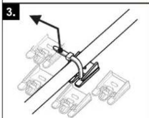

GEFAHR: STROMSCHLAGGEFAHR
natural_image
Technical line drawing of a mechanical assembly with pipes and housing, showing internal components and a small inset image labeled 'a' (no text or symbols beyond label)Dimensions ...04P50D.../...08P50D...
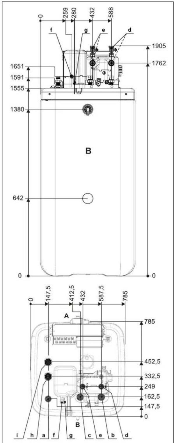
3-2 Dimensions ...04P50D.../...08P50D...
natural_image
Technical line drawing of a mechanical device with mounting brackets and housing (no text or symbols)3–7 Sans capot de recouvrement
natural_image
Technical line drawing of a mechanical assembly with an inset showing a close-up of a component detail (no text or symbols present)natural_image
Technical line drawing of an open computer case with internal components and a downward arrow indicating a component (no text or symbols present)natural_image
Simple line drawing of a rectangular box with a diagonal bar extending from its top, showing a dashed line and an arrow pointing to it (no text or symbols)natural_image
Technical line drawing of a mechanical assembly with gears and housing (no text or symbols)3–22 Bloquer le capot
3.5 Installer les accessoires en option
3–23 Monter le kit de raccordement
a Crochet
b Fente
natural_image
Technical line drawing of an electronic device showing internal components and wiring connections (no text or symbols)natural_image
Mechanical assembly diagram showing a lever mechanism with arrows indicating motion (no text or symbols)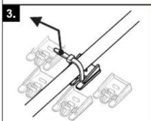
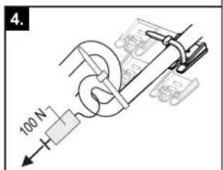
3-41 Raccordement FWX(V/M)-AATV3
[Raccord HP/HC]=1 [Raccord HP/HC]=0
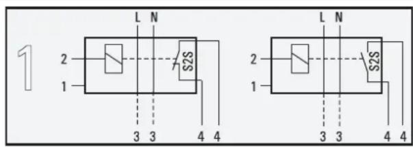
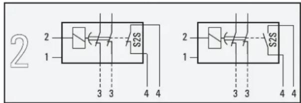
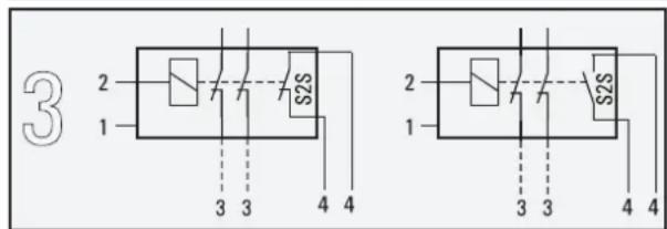
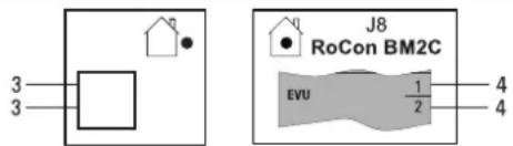
3–43 Raccordement du contact de commutation HT/NT
3–44 Raccordement de Smart Grid
natural_image
Technical line drawing of a mechanical assembly with pipes and housing (no text or symbols)natural_image
Technical line drawing of a mechanical device with mounting holes and internal components (no text or symbols)3–7 Zonder afdekking
3–8 Regelingsbehuizing op servicestand zetten
natural_image
Technical line drawing of a mechanical assembly with an inset showing a close-up of a component detail (no text or symbols present)3–9 Regelingsbehuizing op servicestand
3.4.4 Regelingsbehuizing openen
3–10 Regelingsbehuizing openen
natural_image
Diagram of an open computer case with internal components and a downward arrow indicating a component (no text or symbols present)3–11 Deksel vasthaken
3–15 Hydraulische steekverbindingen

VOORZICHTIG
natural_image
Simple line drawing of a rectangular box with a diagonal saw and dashed arrow indicating a cut or edge (no text or symbols)3–20 Opening in de afdekking maken
natural_image
Technical line drawing of a mechanical assembly with gears and components (no text or symbols)3–22 Kap borgen
natural_image
Technical line drawing of an open computer case with internal components and wiring, showing no text or symbols3–33 Kabeldoorvoer
natural_image
Mechanical assembly diagram showing a lever mechanism with arrows indicating motion (no text or symbols)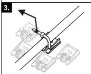
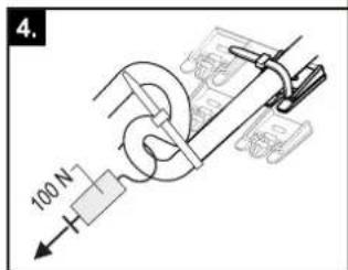
3–34 Trekontlasting maken en controleren
3–43 Aansluiting HT/NT-schakelcontact
natural_image
Technical line drawing of a mechanical assembly with pipes and housing, no visible text or symbols3–5 Retirar el panel frontal
natural_image
Technical line drawing of a mechanical device with housing and mounting components (no text or symbols)natural_image
Technical line drawing of a mechanical device with an inset showing a close-up of its internal structure (no text or symbols present)natural_image
Technical line drawing of an open computer case with internal components and a downward arrow indicating a component (no text or symbols present)3–11 Colgar la tapa
natural_image
Simple line drawing of a rectangular box with a diagonal saw and dashed arrow indicating motion (no text or symbols)natural_image
Technical line drawing of a mechanical assembly with gears and housing (no text or symbols)3-21 Colocar el selector
natural_image
Technical line drawing of an electronic device showing internal components and wiring connections (no text or symbols)3–33 Pasacables
natural_image
Mechanical assembly diagram showing a lever mechanism with arrows indicating motion (no text or symbols)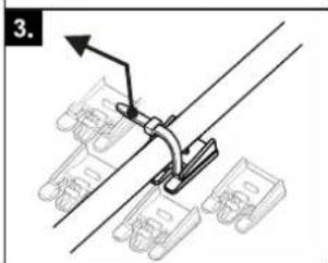
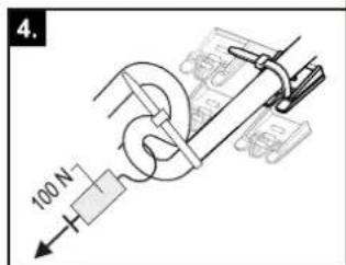
natural_image
Technical line drawing of a mechanical assembly with pipes and housing (no text or symbols)natural_image
Technical line drawing of a mechanical device with housing and mounting components (no text or symbols)natural_image
Technical line drawing of a mechanical device with an inset showing a close-up of its internal components (no text or symbols present)natural_image
Technical line drawing of an open electronic device showing internal components and a downward arrow indicating a component (no text or symbols present)natural_image
Simple line drawing of a rectangular box with a diagonal saw and dashed arrow indicating direction (no text or symbols)natural_image
Technical line drawing of a mechanical assembly with gears and control panel (no text or symbols)RTX-EHS Scheda elettronica (back-up heater)
natural_image
Technical line drawing of an electronic device showing internal components and wiring connections (no text or symbols)3-33 Passacavo
natural_image
Mechanical assembly diagram showing a lever mechanism with arrows indicating motion (no text or symbols)

3–41 Collegamento FWX(V/M)-AATV3
natural_image
Technical line drawing of a mechanical assembly with pipes and housing (no text or symbols)line
| p / bar | U / V | | ------- | ----- | | 0.5 | 0.0 | | 1.0 | 0.5 | | 1.5 | 1.0 | | 2.0 | 1.5 | | 2.5 | 2.0 | | 3.0 | 2.5 | | 3.5 | 3.0 | | 4.0 | 3.5 |3–5 Retirar a placa frontal
3.4.2 Retirar a cobertura protetora
natural_image
Technical line drawing of a mechanical device with mounting brackets and housing (no text or symbols)natural_image
Technical line drawing of a mechanical assembly with an inset showing a close-up of a component detail (no text or symbols present)natural_image
Technical line drawing of an open computer case with internal components and a downward arrow indicating a component (no text or symbols present)3–11 Enganchar a tampa
3-12 Remover o isolamento térmico superior
natural_image
Simple line drawing of a rectangular box with a diagonal saw and dashed arrow indicating direction (no text or symbols)natural_image
Technical line drawing of a mechanical assembly with gears and housing (no text or symbols)3–22 Fixar a cobertura
RTX-EHS Placa de circuitos (backup heater)
natural_image
Technical line drawing of an electronic device showing internal components and wiring connections (no text or symbols)natural_image
Mechanical assembly diagram showing a lever mechanism with mounting brackets and a directional arrow (no text or symbols)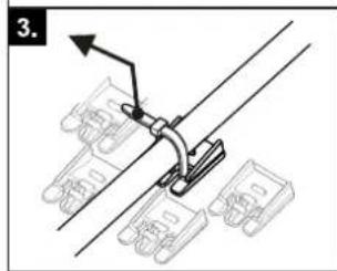
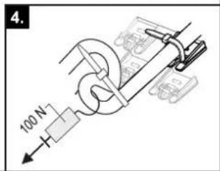
3-41 Ligação FWX(V/M)-AATV3
natural_image
Technical line drawing of a mechanical assembly with pipes and housing (no text or symbols)natural_image
Technical line drawing of a mechanical device with mounting brackets and housing (no text or symbols)3–7 Utan täckkäpa
natural_image
Technical line drawing of a mechanical assembly with an inset showing a close-up of a component detail (no text or symbols present)natural_image
Technical line drawing of an open electronic device showing internal components and a directional arrow (no text or symbols)natural_image
Simple line drawing of a rectangular box with a diagonal saw and dashed curved line, no text or symbols present.natural_image
Technical line drawing of a mechanical assembly with gears and components (no text or symbols)3–22 Säkra kåpa
natural_image
Technical line drawing of an open computer case with internal components and wiring, showing no text or symbolsnatural_image
Mechanical assembly diagram showing a lever mechanism with mounting brackets and a directional arrow (no text or symbols)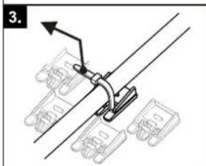
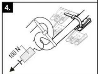
natural_image
Technical line drawing of a mechanical assembly with pipes and housing (no text or symbols)(ackumulatortank) Q,
natural_image
Technical line drawing of a mechanical device with mounting brackets and control panel (no text or symbols)natural_image
Technical line drawing of a mechanical assembly with an inset showing a close-up of a component detail (no text or symbols present)natural_image
Technical line drawing of an open electronic device showing internal components and a directional arrow (no text or symbols)3–11 Zavěšení víka
flowchart
graph TD
    subgraph I
        A["Valve with red valve"] --> B["Pressure Gauge"]
        B --> C["Main Valve"]
        C --> D["Valve with red valve"]
        D --> E["Valve with blue valve"]
        E --> F["Main Valve"]
        F --> G["Valve with red valve"]
        G --> H["Valve with blue valve"]
    end
    subgraph II
        I1["Valve with red valve"] --> J["Main Valve"]
        J --> K["Valve with blue valve"]
        K --> L["Main Valve"]
        L --> M["Valve with red valve"]
        M --> N["Valve with blue valve"]
        N --> O["Main Valve"]
        O --> P["Valve with red valve"]
        P --> Q["Valve with blue valve"]
natural_image
Simple line drawing of a rectangular block with a diagonal saw and dashed line indicating a curved path (no text or symbols)natural_image
Technical line drawing of a mechanical assembly with gears and control panel (no text or symbols)3–22 Zajistěte kryt
natural_image
Technical line drawing of an electronic device showing internal components and wiring connections (no text or symbols)natural_image
Mechanical assembly diagram showing a lever mechanism with mounting brackets and a directional arrow (no text or symbols)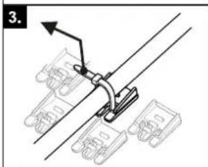
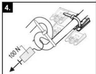
natural_image
Technical line drawing of a mechanical assembly with pipes and housing (no text or symbols)natural_image
Blank grid paper with no text, numbers, or symbols

natural_image
Blank grid paper with no text, numbers, or symbols- Installation and operating manual
- Daikin Altherma 3 R ECH₂O
- General safety precautions 3
- Product description 8
- Set-up and installation 11
- Configuration 30
- Check list for start-up 31
- Technical data 33
- General safety precautions
- Particular safety instructions
- WARNING
- Observing the instructions
- Documentation set
- Meaning of warnings and symbols
- Special warning signs
- Validity
- Handling instructions
- Safety instructions for installation and operation
- General
- Avoid danger
- Before working on the hydraulic system
- Intended use
- Installation room
- CAUTION
- Electrical installation
- Requirements for heating and storage water
- INFORMATION
- Heating system and sanitary connection
- Operation
- Maintenance, troubleshooting and decommissioning
- Recommendations for disposal
- Warranty conditions
- Product description
- Design and components
- Function of the 3-way changeover valves
- Set-up and installation
- Dimensions and connection dimensions
- Transport and delivery
- Scope of delivery
- Installing the heat pump
- Selecting the installation site
- Installation area
- Minimum distance
- DANGER: RISK OF BURNING/SCALDING
- Recommended minimum distances:
- Distances from the outdoor unit:
- Installing the device
- Precondition
- Set-up
- Preparing the device for installation
- Remove the front screen
- Remove the protective cover
- Moving the switch box to the service position
- Open the switch box
- Removing the bottom thermal insulation
- Opening the air purge valve
- Aligning the connections of the heating inflow and return flow
- Making the hood opening
- Installing the rotary switch of the controller
- Securing the hood
- Installing optional accessories
- Installation of electric backup heater (EKBUxx)
- Installation of the external heat generator connection set (EKBUHSWB)
- Installation of the DB connection kit
- Installation of the P connection kit
- Water connection
- CAUTION: BIV only
- Minimum water volume
- Connecting hydraulic lines
- Connecting the drain
- Electrical connection
- DANGER: RISK OF ELECTROCUTION
- Overall connection diagram
- Position of the PCBs and terminal strips
- Mains connection
- General information on the electrical connection
- Connecting the heat pump outdoor unit
- Connecting the outdoor temperature sensor (optional)
- External switching contact
- EBA (external requirement request)
- Connecting an external heat generator
- Connecting the room thermostat
- Connection of optional RoCon system components
- EHS157034 room controller
- EHS157068 mixer module
- EHS157056 Internet gateway
- Connecting the HP convector
- Connecting switching contacts (AUX outputs)
- Low rate mains connection (HT/NT)
- Connecting an intelligent controller (Smart Grid - SG)
- Connection for refrigerant
- Laying refrigerant piping
- Pressure test and filling the refrigerant circuit
- Filling the system
- Checking the water quality and adjusting the manometer
- Filling hot water heat exchangers
- Filling the storage tank
- Without installed solar system
- With installed solar system
- Filling the heating system
- Configuration
- Check list for start-up
- Requirements
- Commissioning at low ambient temperatures
- With electrical backup heater:
- Without electrical backup heater:
- Bleeding the hydraulic system
- Checking the minimum flow
- Start screed drying (only if required)
- Commissioning checklist
- Handover to the operating company
- Technical data
- Information on the type plate
- Characteristic lines
- Sensor characteristic lines
- Tightening torques
- Minimum floor area and ventilation openings
- Piping diagram for refrigerant circuit
- Inhaltsverzeichnis
- ACHTUNG
- Optionales Zubehör installieren
- GEFAHR: STROMSCHLAGGEFAHR
- Installer les accessoires en option
- Regelingsbehuizing openen
- VOORZICHTIG
- Retirar a cobertura protetora
Brand : DAIKIN
Model : EHSH04P30D3
Category : Air-conditioner