
DPS-200A - Power Supply D-LINK - Free user manual and instructions
Find the device manual for free DPS-200A D-LINK in PDF.

| Product Type | Redundant Power Supply (RPS) |
| Brand | D-Link |
| Model | DPS-200A |
| Input Voltage | 100 to 240 V AC |
| Input Frequency | 50-60 Hz |
| Input Current | 1.5 A |
| Output Voltage | 12 V DC |
| Output Current | 13 A |
| Operating Temperature | 0 to 50 °C |
| Connector Type | 14-pin DC power cable |
| Main Features | Redundant power supply for switches, built-in monitoring, automatic switchover on failure, rack mountable via DPS-800 |
| Maintenance and Cleaning | Disconnect before cleaning; use a soft, dry cloth |
| Safety | Class A product; do not expose to moisture; disconnect before connecting to the switch |
| Spare Parts and Repairability | Contact D-Link for spare parts; repair by qualified personnel |
| General Information | User manual included; limited warranty available online; environmentally friendly recycling (crossed-out wheelie bin symbol) |
| Pin Assignment | Pin 1: Ground, Pins 3-6: +12 V, Pin 10: RPS present, Pin 13: PWR-Good |
| Rack Compatibility | Installable in RPS DPS-800 rack (1.25U) |
| LED Indicator | Green LED on front indicating successful connection |
Frequently Asked Questions - DPS-200A D-LINK
User questions about DPS-200A D-LINK
0 question about this device. Answer the ones you know or ask your own.
Ask a new question about this device
Download the instructions for your Power Supply in PDF format for free! Find your manual DPS-200A - D-LINK and take your electronic device back in hand. On this page are published all the documents necessary for the use of your device. DPS-200A by D-LINK.
USER MANUAL DPS-200A D-LINK
Quick Installation Guide for Redundant Power Supply
DPS-200A, 500A and 500DC
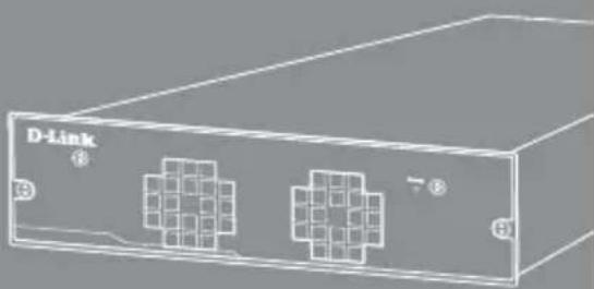
natural_image
Illustration of a D-Link device with two connected ports and grid patterns (no text or symbols)Getting Started Guide
Erste Schritte
Guide de démarrage
Guida introduttiva
The D-Link DPS-200A, 500A, and 500DC are redundant power supplies designed to be mounted into a standard rack and provide an affordable solution to provide a constant power source. This guide gives step-by-step instructions for setting up the DPS-200A, 500A, and 500DC with a switch that supports power over a 14-pin DC power cable. Please note that the model you have purchased may appear slightly different from those shown in the illustrations.
For more detailed information about your switch, its components, making network connections, and technical specifications, please refer to the User's Guide included with your switch.
Introduction
A redundant power supply provides a low-cost, simple solution to the equally simple yet vexing problem of internal power supply failure, which can result in the shutdown of a single switching device or an entire network.
With a redundant power supply connected, an integrated detection circuit continuously monitors the switch's internal power supply. In the event of a power interruption, the redundant power supply is immediately triggered so that the switch and connected devices can continue providing service.
This results in a more reliable network infrastructure and protects the network from a single failure of a network device power supply.
Description
The DPS-200A, DPS-500A and DPS-500DC are redundant power supply units designed to conform to the wattage requirements of the switches being supported.
The DPS-200A, DPS-500A and DPS-500DC can connect to the master switch using a 14-pin DC power cable. A standard, three-pronged AC power cable connects the redundant power supply to the main power source.
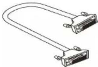
natural_image
Line drawing of two Ethernet connectors with I/O ports (no text or symbols)14-pin DC power cable
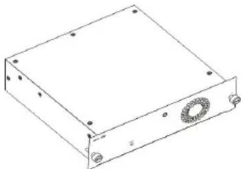
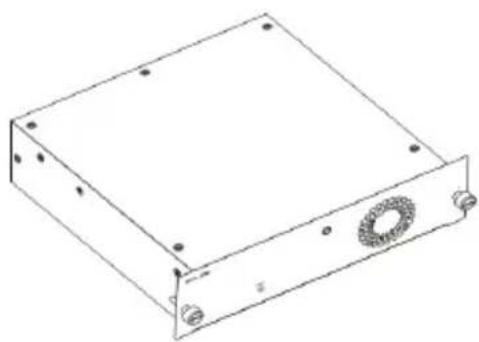
natural_image
Line drawing of a rectangular electronic device with mounting holes and a circular component (no text or symbols)Single RPS (DPS-200A /DPS-500A/DPS-500DC)
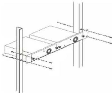
Rack Installation
The single RPS DPS-200A, 500A, and 500DC can be installed to the standard rack via the RPS rack DPS-800. The DPS-800 is a standard-size rack mount (1.25U in height) designed to hold up to 2 redundant power supplies. Installed RPS units can be DPS-200As, DPS-500As, DPS-500DCs, or a combination of the above.
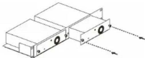
natural_image
Technical line drawing of two rectangular electronic components with mounting holes and dashed arrows indicating direction (no text or symbols)Inserting a single RPS into a DPS-800 RPS rack
natural_image
Technical line drawing of a mechanical assembly with mounting holes and vertical supports (no text or symbols)Installing a DPS-800 in a standard electronics rack
Switch Connection
Caution: The redundant power supply should be disconnected from its power source before connecting to the switch. Directly connecting a powered RPS to the switch may cause damage to the switch's internal power supply.
Insert one end of the DC power cable into the receptacle on the switch and the other end into the redundant power supply.
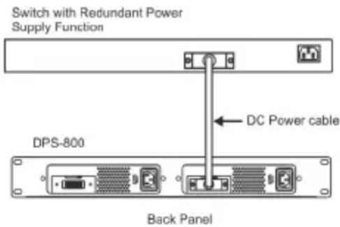
Connecting a single RPS in a DPS-800 rack to a switch
Power Connection
Connecting AC Power (DPS-200A/500A)
Using a standard AC power cable, connect the redundant power supply to the main AC power source. A green LED on the front of the DPS-200A/DPS-500A will glow to indicate a successful connection.
Connecting DC Power (DPS-500DC)
-
Firmly attach the DC power source to the negative and positive contacts on the wiring assembly.
-
The negative pole (-) connects to the -48V contact.
- The positive pole (+) connects to the -48V RTN contact.
-
If available, an earth ground may be connected to the center contact post.
-
Tighten the contact screws to secure the connection.
No change in switch configuration is necessary when connecting to the RPS.
Product Specification
| Model Name | DPS-200A D | PS-500A DPS | -500DC |
| Input Voltage | 100 to 240 V AC | 100 to 240 V AC | -36 to 72 V DC |
| Input Frequency | 50-60 Hz 50-60 Hz - | ||
| Input Current | 1.5 A 4 A | 6 A | |
| Output Voltage | 12 V 12 V | 12 V | |
| Output Current | 13 A 13 A | 12.5 A | |
| Operation Temperature | 0 to 50°C 0 | to 50°C 0 to 50°C | |
Pin Assignment
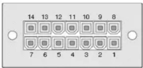
| Pin DPS-200A/500A/500DCA | |
| 1 | GND |
| 2 | N/C |
| 3 | +12 V |
| 4 | +12 V |
| 5 | +12 V |
| 6 | +12 V |
| 7 | GND |
| 8 | N/C |
| 9 | N/C |
| 10 | RPS Present |
| 11 | N/C |
| 12 | N/C |
| 13 | PWR-Good |
| 14 | GND |
Additional Information
Additional help is available through our offices listed at the back of the user manual or online. To find out more about D-Link products or marketing information, please visit the website http://www.dlink.com.
Warranty Information
The D-Link Limited Lifetime Warranty information is available at http://warranty.dlink.com/
natural_image
Line drawing of two Ethernet connectors with I/O ports (no text or symbols)natural_image
Line drawing of a rectangular electronic device with mounting holes and a circular component (no text or symbols)natural_image
Technical line drawing of a mechanical assembly with mounting holes and directional arrows (no text or symbols)natural_image
Technical line drawing of a mechanical assembly with mounting holes and vertical supports (no text or symbols)Back Panel
natural_image
Line drawing of two connected USB connectors (no text or symbols)natural_image
Line drawing of a rectangular electronic device with mounting holes and a circular component (no text or symbols)Alimentation redondante (RPS) simple (DPS-200A /DPS-500A/DPS-500DC)
natural_image
Technical line drawing of a mechanical assembly with mounting holes and directional arrows (no text or symbols)natural_image
Technical line drawing of a mechanical assembly with mounting holes and vertical supports (no text or symbols)natural_image
Line drawing of two Ethernet connectors with I/O port (no text or symbols)natural_image
Line drawing of a rectangular electronic device with mounting holes and a circular component (no text or symbols)RPS individual (DPS-200A /DPS-500A/DPS-500DC)
natural_image
Technical line drawing of a mechanical assembly with mounting holes and directional arrows (no text or symbols)natural_image
Technical line drawing of a mechanical assembly with mounting holes and dimension lines (no text or symbols)Back Panel
natural_image
Line drawing of a U-shaped cable with two connectors (no text or symbols)natural_image
Line drawing of a rectangular electronic device with mounting holes and a circular component (no text or symbols)Singolo RPS (DPS-200A /DPS-500A/DPS-500DC)
natural_image
Technical line drawing of a mechanical assembly with mounting brackets and directional arrows indicating motion (no text or symbols)natural_image
Technical line drawing of a mechanical assembly with mounting holes and vertical supports (no text or symbols)natural_image
Line drawing of two Ethernet connectors (no text or symbols)natural_image
Line drawing of a rectangular electronic device with mounting holes and a circular component (no text or symbols)RPS (DPS-200A/DPS-500A/DPS-500DC)
Установка в стойку
natural_image
Technical line drawing of two electronic components with mounting holes and dashed arrows indicating direction (no text or symbols)natural_image
Technical line drawing of a mechanical assembly with mounting holes and vertical supports (no text or symbols)natural_image
Line drawing of two Ethernet cable connectors (no text or symbols)14-pin DC 電源線
natural_image
Line drawing of a rectangular electronic device with mounting holes and a circular component (no text or symbols)natural_image
Technical line drawing of two electronic device units with mounting holes and directional arrows indicating motion (no text or symbols)natural_image
Technical line drawing of a mechanical assembly with mounting holes and vertical supports (no text or symbols)將 DPS-800 安裝於標準機櫃中
交換器的連接
This equipment has been tested and found to comply with the limits for a Class A digital device, pursuant to Part 15 of the FCC Rules. These limits are designed to provide reasonable protection against harmful interference when the equipment is operated in a commercial environment. This equipment generates, uses, and can radiate radio frequency energy and, if not installed and used in accordance with this manual, may cause harmful interference to radio communications. Operation of this equipment in a residential area is likely to cause harmful interference in which case the user will be required to correct the interference at his own expense.
CE Mark Warning
This is a Class A product. In a domestic environment, this product may cause radio interference in which case the user may be required to take adequate measures.
Warnung!
Warranty Information
The D-Link Limited Lifetime Warranty information is available at http://warranty.dlink.com/
SAFETY INSTRUCTIONS
Please adhere to the following safety guidelines to help ensure your own personal safety and protect your system from potential damage. Any acts taken that are inconsistent with ordinary use of the product, including improper testing, etc., and those not expressly approved by D-Link may result in the loss of product warranty.
Unless expressly approved by an authorized representative of D-Link in writing, you may not and may not permit others to:
- Disassemble or reverse engineer the device or attempt to derive source code (underlying ideas, algorithms, or structure) from the device or from any other information provided by D-Link, except to the extent that this restriction is expressly prohibited by local law.
- Modify or alter the device.
- Remove from the device any product identification or other notices, including copyright notices and patent markings, if any.
To reduce the risk of bodily injury, electrical shock, fire, and damage to the device and other equipment, observe the following precautions:
Power Sources
- Observe and follow service markings.
- Do not push any objects into the openings of your device unless consistent with the authorized operation of the device. Doing so can cause a fire or an electrical shock by shorting out interior components.
- The powering of this device must adhere to the power specifications indicated for this product.
- Do not overload wall outlets and/or extension cords as this will increase the risk of fire or electrical shock.
- Do not rest anything on the power cord or on the device (unless the device is made and expressly approved as suitable for stacking).
- Position system cables and power cables carefully; route cables so that they cannot be stepped on or tripped over. Be sure that nothing rests on any cables.
- Operate the device only from the type of external power source indicated on the electrical ratings label.
- To help avoid damaging your device, be sure the voltage selection switch (if provided) on the power supply is set to match the power available at your location.
- Also be sure that attached devices are electrically rated to operate with the power available in your location.
- Use only approved power cable(s). If you have not been provided a power cable for your device or for any AC-powered option intended for your device, purchase a power cable that is approved for use in your country and is suitable for use with your device. The power cable must be rated for the device and for the voltage and current marked on the device's electrical ratings label. The voltage and current rating of the cable should be greater than the ratings marked on the device.
- To help prevent an electrical shock, plug the device and peripheral power cables into properly grounded electrical outlets. These cables are equipped with three-prong plugs to help ensure proper grounding. Do not use adapter plugs or remove the grounding prong from a cable. If you must use an extension cable, use a 3-wire cable with properly grounded plugs.
- Observe extension cable and power strip ratings. Ensure that the total ampere rating of all products plugged into the extension cable or power strip does not exceed 80 percent of the ampere ratings limit for the extension cable or power strip.
- To help protect your device from sudden, transient increases and decreases in electrical power, use a surge suppressor, line conditioner, or uninterruptible power supply (UPS).
- Do not modify power cables or plugs. Consult a licensed electrician or your power company for site modifications. Always follow your local/national wiring rules.
- When connecting or disconnecting power to hot-pluggable power supplies, if offered with your device, observe the following guidelines:
• Install the power supply before connecting the power cable to the power supply.
- Unplug the power cable before removing the power supply.
- If the system has multiple sources of power, disconnect power from the device by unplugging all power cables from the power supplies.
Servicing/Disassembling
- Do not service any product except as expressly set forth in your system documentation.
- Opening or removing covers that are marked with the triangular symbol with a lightning bolt may expose you to an electrical shock. Only a trained service technician should service components inside these compartments.
- To reduce the risk of electrical shock, never disassemble this device. None of its internal parts are user-replaceable; therefore, there is no reason to access the interior.
- Do not spill food or liquids on your system components, and never operate the device in a wet environment. If the device gets wet, see the appropriate section in your troubleshooting guide or contact your trained service provider.
- Use the device only with approved equipment.
- Move products with care; ensure that all casters and/or stabilizers are firmly connected to the system. Avoid sudden stops and uneven surfaces.
Environment
- Do not use this device near water (e.g. near a bathtub, sink, laundry tub, fish tank, in a wet basement or near a swimming pool).
- Do not use this device in areas with high humidity.
- This device must not be subjected to water or condensation.
- Keep your device away from radiators and heat sources. Also, do not block cooling vents.
Cleaning
• Always unplug the power before cleaning this device.
- Do not use liquid or aerosol cleaners of any kind. Use only compressed air that is recommended for electronic devices.
- Use a dry cloth for cleaning.
PROTECTING AGAINST ELECTROSTATIC DISCHARGE
Static electricity can harm delicate components inside your system. To prevent static damage, discharge static electricity from your body before you touch any of the electronic components, such as the microprocessor. You can do so by periodically touching an unpainted metal surface on the chassis.
You can also take the following steps to help prevent damage from electrostatic discharge (ESD):
- When unpacking a static-sensitive component from its shipping carton, do not remove the component from the antistatic packing material until you are ready to install the component in your system. Just before unwrapping the antistatic packaging, be sure to discharge static electricity from your body.
- When transporting a sensitive component, first place it in an antistatic container or packaging.
- Handle all sensitive components in a static-safe area. If possible, use antistatic floor pads, workbench pads, and an antistatic grounding str
EUROPEAN COMMUNITY DECLARATION OF CONFORMITY
This equipment complies with the essential requirements and other provisions of Directives 2004/108/EC and 2006/95/EC. For more information, please refer to the Declaration of Conformity.
WARNING STATEMENT
The power outlet should be nearby the device and easily accessible.
DISPOSING AND RECYCLING YOUR PRODUCT

ENGLISH
EN


This symbol on the product or packaging means that according to local laws and regulations this product should be not be disposed of in the household waste but sent for recycling. Please take it to a collection point designated by your local authorities once it has reached the end of its life, some will accept products for free. By recycling the product and its packaging in this manner you help to conserve the environment and protect human health.
D-Link and the environment
At D-Link, we understand and are committed to reducing any impact our operations and products may have on the environment. To minimise this impact D-Link designs and builds its products to be as environmentally friendly as possible, by using recyclable, low toxic materials in both products and packaging.
D-Link recommends that you always switch off or unplug your D-Link products when they are not in use. By doing so you will help to save energy and reduce CO2 emissions.
To learn more about our environmentally responsible products and packaging please visit www.dlinkgreen.com
DEUTSCH
DE


- Quick Installation Guide for Redundant Power Supply
- Introduction
- Description
- Rack Installation
- Switch Connection
- Power Connection
- Connecting AC Power (DPS-200A/500A)
- Connecting DC Power (DPS-500DC)
- Additional Information
- Warranty Information
- Установка в стойку
- 交換器的連接
- CE Mark Warning
- Warnung!
- SAFETY INSTRUCTIONS
- Power Sources
- Servicing/Disassembling
- Environment
- Cleaning
- PROTECTING AGAINST ELECTROSTATIC DISCHARGE
- EUROPEAN COMMUNITY DECLARATION OF CONFORMITY
- WARNING STATEMENT
- DISPOSING AND RECYCLING YOUR PRODUCT
- ENGLISH
- EN
- D-Link and the environment
- DEUTSCH
- DE
Brand : D-LINK
Model : DPS-200A
Category : Power Supply