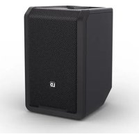
ANNY 8 - Loudspeaker LD Systems - Free user manual and instructions
Find the device manual for free ANNY 8 LD Systems in PDF.


| Product type | Battery-powered active PA speaker |
| Brand | LD Systems |
| Model | ANNY 8 |
| Dimensions (W x D x H) | 249 x 282 x 390 mm |
| Weight | 9.04 kg |
| Total power (RMS) | 80 W |
| Total power (peak) | 160 W |
| Max SPL (average) | 110 dB |
| Frequency response (-10 dB) | 53 Hz – 20 kHz |
| Mains power supply | 100-240 V, 50/60 Hz, 150 W |
| Battery | Li-ion 14.8 V / 5000 mAh, runtime up to 11 h (ECO mode) |
| Bluetooth | Version 5.0, codecs SBC/AAC, TWS stereo streaming |
| Audio inputs | 2 x Combo (XLR/6.35 mm jack) mic/line, 1 x 3.5 mm stereo jack, 2 x RCA, 1 x USB-C (charging) |
| Mix output | 1 x XLR male |
| Integrated mixer | 5 channels, 3-band EQ, reverb, delay, priority mode |
| Controls | Main volume (encoder), channel volumes, MIC/LINE selectors, effect, screen menu |
| Display | Multifunction LCD screen |
| Additional features | ECO mode, smartphone/tablet holder, 35 mm pole mount, carrying handle |
| Maintenance | Clean surfaces with a damp cloth, dust off grilles |
| Repairability | User-replaceable battery, other repairs by qualified personnel |
| Included accessories | Mains cable, manual; HHD/BPH versions include receiver module and microphone |
Frequently Asked Questions - ANNY 8 LD Systems
User questions about ANNY 8 LD Systems
0 question about this device. Answer the ones you know or ask your own.
Ask a new question about this device
Download the instructions for your Loudspeaker in PDF format for free! Find your manual ANNY 8 - LD Systems and take your electronic device back in hand. On this page are published all the documents necessary for the use of your device. ANNY 8 by LD Systems.
USER MANUAL ANNY 8 LD Systems
natural_image
Black rectangular electronic device with mesh grille and 'LD' logo on front panel (no text or symbols beyond branding)ANNY® 8
8" PORTABLE BATTERY-POWER®A BICUERSPOAKER LDANNY8 (W/GN/BG) (HHD/BPH)
CONTENTS / INHALTSVERZEICHNIS / CONTENU / CONTENIDO / TREŚĆ / CONTENUTO
ENGLISH
INFORMATION ON THIS USER MANUAL 4
INTENDED USE 4
DEFINITIONS AND SYMBOL EXPLANATIONS 4
SAFETY INSTRUCTIONS 5
NOTES FOR PORTABLE INDOOR DEVICES 10
PACKAGING CONTENT 10
TRANSPORT HANDLE AND
CARE, MAINTENANCE, AND REPAIR 27
REPLACING DEVICE BATTERIES 28
OPTIONAL ACCESSORIES 29
TECHNICAL DATA 30
DISPOSAL 34
MANUFACTURER'S DECLARATIONS 35
DEUTSCH
INFORMATIONEN ZU DIESER
This device has been developed and manufactured to the highest standards of quality to ensure many years of trouble-free operation. This is what the name LD Systems stands for as well as its long-standing experience as a manufacturer of high-quality audio products. Please read the user manual carefully to get the most out your new LD systems product.
You can find more information on LD Systems on our website WWW.LD-SYSTEMS.COM
INFORMATION ON THIS USER MANUAL
- Carefully read the safety instructions and the entire manual before operating the device.
- Observe the warnings on the device and in the user manual.
- Always keep the user manual within reach.
- If you sell or pass on the device, it is important that you also include this user manual, as it is an integral part of the product.
INTENDED USE
This product is a device for event technology!
The product has been developed for professional use in event technology and is not intended for use in the home!
Furthermore, this product is only intended for qualified users with specialist knowledge of event technology!
Use of the product outside the specified technical data and operating conditions is considered improper use!
Liability for damage and third-party damage to persons and property due to inappropriate use is excluded!
• The product is not suitable for:
- Children (children must be instructed not to play with the device).
- Persons with limited physical, sensory, or mental abilities or with a lack of experience and knowledge.
DEFINITIONS AND SYMBOL EXPLANATIONS
- DANGER: The word DANGER, possibly in combination with a symbol, indicates immediately hazardous situations or conditions risking life and limb.
- WARNING: The word WARNING, possibly in combination with a symbol, indicates potentially hazardous situations or conditions risking life and limb.
- CAUTION: The word CAUTION, possibly in combination with a symbol, indicates situations or conditions that may lead to injury.
- ATTENTION: The word ATTENTION, possibly in combination with a symbol, indicates situations or conditions that may lead to damage to property and/or the environment.
This symbol identifies hazards that can cause electric shock.

This symbol identifies hazardous areas or hazardous situations.

This symbol indicates hazards caused by hot surfaces.

This symbol indicates hazards due to high volume levels.

This symbol indicates additional information on the operation of the product.

This symbol denotes a device that does not contain any user-serviceable parts.

This symbol indicates a device that may only be used in dry rooms.
SAFETY INSTRUCTIONS
DANGER:
- Do not open the device, and do not make any modifications to it.
- If your device no longer functions properly, if liquids or objects get inside it, or if it has been damaged in any other way, switch it off immediately and disconnect it from the power supply. The device may be repaired only by authorised repair technicians.
- For devices of protection class 1, the protective conductor must be connected correctly. Never disconnect the protective conductor. Devices of protection class 2 do not have a protective conductor.
- Ensure that live cables are not kinked or otherwise mechanically damaged.
- Never bypass the device fuse.
WARNING:
- The device may not be operated if it shows obvious signs of damage.
- The device may only be installed in a voltage-free state.
- If the device's mains cable is damaged, the device should not be used.
- Permanently connected mains cables may only be replaced by a qualified person.
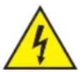
ATTENTION:
- Do not operate the device if it has been exposed to large temperature fluctuations (for example after transport). Moisture and condensation can damage the device. Switch on the device only when it has reached ambient temperature.
- Make sure that the voltage and frequency of the mains correspond to the values specified on the device. If the device has a voltage selector switch, do not turn the device on until it has been set correctly. Use only suitable mains cables.
- To disconnect the device from the mains on all poles, it is not sufficient to press the on/off switch on the device.
- Make sure that the fuse used corresponds to the type specified on the device.
- Make sure that appropriate measures have been taken against power surges (for example lightning strike).
- Observe the specified maximum output current on devices with Power Out connection. Ensure that the total current consumption of all connected devices does not exceed the specified value.
- Replace pluggable mains cables only with original cables.
- Connect the device only to compliant, tested, and undamaged mains supply devices.

DANGER:
- Danger of suffocation/choking! Plastic bags and small parts must be kept out of reach of children and persons with limited physical, sensory, or mental abilities.
- Danger caused by falling device! Make sure that the device is securely installed and cannot fall down. Only use suitable stands or mounts (particularly for fixed installations). Ensure that accessories are properly installed and secured. Ensure that all applicable safety regulations are observed.

WARNING:
- Use the device in the prescribed manner only.
- Operate the device only with the accessories recommended and intended by the manufacturer.
- During installation, observe the safety regulations applicable in your country.
- After connecting the device, check all cable routes to avoid damage or accidents, for example due to tripping hazards.
- Always observe the specified minimum distance to normally flammable materials! Unless explicitly stated, the minimum distance is 0.3 m.
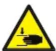
CAUTION:
- Moving components such as mounting brackets or other movable components may become jammed.

ATTENTION:
- Do not install or use the device in the vicinity of radiators, heat accumulators, furnaces, or other heat sources. Ensure that the device is always installed in such a way that it is sufficiently cooled and cannot overheat.
- Do not place ignition sources such as burning candles near the device.
- Ventilation openings must not be covered, and fans must not be blocked.
- Use the original packaging or packaging provided by the manufacturer for transport.
- Avoid shock or impact to the device.
- Observe the IP protection class as well as the ambient conditions such as temperature and humidity according to the specification.
- Devices can be continuously further developed. In the event of deviating information on operating conditions, performance, or other device properties between the user manual and the device labelling, the information provided on the device always has priority.
- The device is not suitable for tropical climates or for operation at heights of 2,000 m or more above sea level.

CAUTION:
Connecting signal cables can cause significant interference noise. Make sure that devices connected to the output are muted while making connections. Otherwise, noise levels may cause damage.
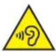
ATTENTION: HIGH-VOLUME AUDIO PRODUCTS!
This device is designed for professional use.
The commercial operation of this device is subject to the applicable national regulations and guidelines for accident prevention.
Hearing damage due to high volume and continuous exposure: use of this product may generate high sound pressure levels (SPLs) that may cause hearing damage. Avoid exposure to high volumes.

RADIO SIGNAL TRANSMISSION (for example, W-DMX or audio radio systems, Bluetooth):
The quality and performance of wireless signal transmissions generally depends on the ambient conditions.
For example, the following factors can impact range and signal quality:
- Shielding (for example masonry, metal structures, water)
• High volumes of radio traffic (for example powerful wireless LAN networks) - Interference
- Electromagnetic radiation (for example LED video screens, dimmers)
All range specifications refer to free-field line-of-sight applications without interference!
The operation of radio transmission systems is subject to official regulations. These may vary from region to region and must be checked by the operator before use (for example radio frequency and transmission power).

WARNING:
Wireless transmitting devices are not suitable for use in sensitive areas in which radio operation can lead to potential detrimental effects. These include:
• Hospitals, health centres, or other healthcare facilities that provide patient treatment with skilled personnel and equipment
• Class I, II, and III ex zones
- Restricted areas
• Military facilities
- Aircraft or vehicles
- Areas where the use of mobile phones is prohibited

BATTERY DEVICES AND CHARGERS
DANGER:
- Keep the battery-powered device away from heat sources, and do not expose it to direct sunlight. Do not place it on or in heating appliances such as microwaves, ovens, or radiators. Batteries can explode if overheated. Always observe the care instructions and ensure the ambient conditions are appropriate! These are detailed in the technical specifications.
- Do not open the device! Do not modify the battery, and do not attempt to replace the battery cells!
- Battery cells or battery packs must not be damaged. Protective films and stickers must not be removed. No foreign objects may be inserted into the battery. Do not allow any liquids to enter the battery. There is a danger of fire and explosion as well as a danger of other hazardous situations (for example, outgassing).
- If the device becomes deformed or overheats, stop using it immediately! If you continue to operate the device, there is a danger of fire and explosion as well as a danger of other hazardous situations (for example, outgassing).
- Do not throw the device into a fire! Danger of explosion!
- Do not subject the device to strong mechanical effects! Damage caused by falling, crushing, or piercing, as well as high pressure, leads to a danger of fire and explosion as well as a danger of other hazardous situations (for example, outgassing).
- Only charge the device or battery in the intended manner. Only use the original charger. Please note that a compatible plug connection is not an indication of the charger's suitability.
- Please note that device's main switch does not deactivate the charging function on all devices.
- In the case of charging devices built into transport cases, charging may only be carried out when the lid is open.
- Leaked fluid is corrosive and can be toxic. It can cause skin and eye irritations and is dangerous if swallowed. Avoid any contact with leaked fluid. In the event of contact with leaked fluid, immediately wash the affected area with plenty of water and contact a doctor.

DEVICES WITH USER-SERVICEABLE DISPOSABLE OR RECHARGEABLE BATTERIES DANGER:
Always observe the manufacturer's data sheet for disposable or rechargeable batteries!
- Disposable and rechargeable batteries must be kept out of reach of children and persons with limited physical, sensory, or mental abilities. Danger of choking posed by swallowing small parts!
- Do not subject disposable and rechargeable batteries to strong mechanical forces! Damage caused by falling, crushing, or piercing, as well as high pressure, leads to a danger of fire and explosion as well as a danger of other hazardous situations (for example, outgassing).
- Leaked battery fluid is corrosive and can be toxic. It can cause skin and eye irritations and is dangerous if swallowed. Avoid any contact with leaked fluid. In the event of contact with leaked fluid, immediately wash the affected area with plenty of water and contact a doctor.
- Do not attempt to charge non-rechargeable batteries. Danger of explosion!
- Do not throw disposable and rechargeable batteries in a fire! Danger of explosion!
- Do not short-circuit disposable and rechargeable batteries! Avoid contact between the battery terminals and electrically conductive objects (for example, key ring, coins, tools).

ATTENTION:
- Ensure correct polarity when inserting disposable and rechargeable batteries (see diagrams in the battery compartment, on the housing, or in these instructions).
- Do not use different types of battery cells or battery brands in a device at the same time.
- Only use disposable and rechargeable batteries with the same discharge status.
- Check the disposable and rechargeable batteries for damage, and do not use any damaged disposable and rechargeable batteries.

CHARGING, USING, AND STORING BATTERIES
- To charge permanently installed batteries, connect the device to the correct power supply. Please note that the device's main switch does not deactivate the charging function on all devices.
- The charging time for a full charge of the battery can be found in the technical data. Information on the battery status can be found in the chapter OPERATION.
- Devices with lithium batteries are equipped with standard protective features.
- Do not charge the battery outside the ambient conditions specified in the technical data. Unless otherwise specified, these are between +5°C and +35°C in dry environments.
- The permissible ambient conditions for operation can be found in the technical data. Unless otherwise specified, these must not be below +5°C or above +35°C in dry environments.
- The permissible ambient conditions for storage can be found in the technical data. Unless otherwise specified, these must not be below +5°C or above +35°C in dry environments
- Fully recharge the battery immediately after discharge.
- Only store the device with a fully charged battery. Batteries that are not fully charged m lose capacity and service life prematurely.
- If the device is not used over a longer period, perform a full charge cycle no later than every three months.
- The device's main switch must be switched off during storage.
- The battery operating times specified always refer to a new battery and normal operational conditions.
- The battery operating time may be shorter than specified when operated in cold environments.
- If the operating time of the device in battery operation deviates significantly from the specifications, please contact your distribution partner.

NOTES FOR PORTABLE INDOOR DEVICES
- Temporary operation! Event equipment is generally designed for temporary use only.
- Continuous operation or permanent installation can impair the functioning of the device and cause premature ageing.
PACKAGING CONTENT
Remove the product from the packaging and remove all packaging material.
Please check the completeness and integrity of the delivery and notify your distribution partner immediately after purchase if the delivery is not complete or if it is damaged.
The packaging content for the product ANNY 8 includes:
- 1× ANNY 8 speaker, Stage black
- 1 × mains cable
- User manual
The packaging content for the product ANNY 8 HHD includes:
• 1× ANNY 8 speaker, Stage black
- 1× handheld transmitter + 2× AA battery
- 1× receiver module + antenna
- 1× mains cable
- User manual
The packaging content for the product ANNY 8 BPH includes:
- 1× ANNY 8 speaker, Stage black
- 1× pocket transmitter + headset + 2× AA battery
- 1× receiver module + antenna
- 1× mains cable
- User manual
The packaging content for the product ANNY 8 W includes:
- 1× mains cable
- User manual
- 1× ANNY 8 speaker, Pure white
The packaging content for the product ANNY 8 W HHD includes:
- 1× ANNY 8 speaker, Pure white
- 1× handheld transmitter + 2× AA battery
- 1× receiver module + antenna
- 1× mains cable
- User manual
The packaging content for the product ANNY 8 W BPH includes:
- 1× ANNY 8 speaker, Pure white
- 1× pocket transmitter + headset + 2× AA battery
- 1× receiver module + antenna
- 1× mains cable
- User manual
The packaging content for the product ANNY 8 BG includes:
• 1× ANNY 8 speaker, Urban grey
- 1× mains cable
- User manual
The packaging content for the product ANNY 8 BG HHD includes:
• 1× ANNY 8 speaker, Urban grey
- 1× handheld transmitter + 2× AA battery
- 1× receiver module + antenna
- 1× mains cable
- User manual
The packaging content for the product ANNY 8 BG BPH includes:
• 1× ANNY 8 speaker, Urban grey
- 1× pocket transmitter + headset + 2× AA battery
- 1× receiver module + antenna
- 1× mains cable
- User manual
The packaging content for the product ANNY 8 GN includes:
• 1× ANNY 8 speaker, Adventure green
- 1× mains cable
- User manual
The packaging content for the product ANNY 8 GN HHD includes:
• 1× ANNY 8 speaker, Adventure green
- 1× handheld transmitter + 2× AA battery
- 1× receiver module + antenna
- 1× mains cable
- User manual
The packaging content for the product ANNY 8 GN BPH includes:
• 1× ANNY 8 speaker, Adventure green
- 1× pocket transmitter + headset + 2× AA battery
- 1× receiver module + antenna
- 1× mains cable
- User manual
FEATURES
- Portable active two-way full-range loudspeaker
• Built-in 5-channel mixer with three-band EQ, reverb, and delay - Long battery life: up to 11 h (ECO mode)/3.5 h (max. volume)
- Tilt-back cabinet to switch listening angles
- Bluetooth® 5.0 and stereo streaming (TWS) with two ANNYs
- Clear and distortion-free sound at maximum volume through DynX® DSP (Gen. 2)
- 2× microphone/line inputs for versatile connection options
- 1× stereo channel with 3.5 mm jack (AUX) or RCA
- Priority/ducking mode to emphasise the microphone signal
- Practical handle for easy carrying
- 35 mm flange for use with a speaker stand
- USB-C port for charging a tablet or smartphone
- Footswitch input for hands-free effect control
- Integrated holder for tablet or smartphone
TRANSPORT HANDLE AND SMARTPHONE/TABLET TRAY
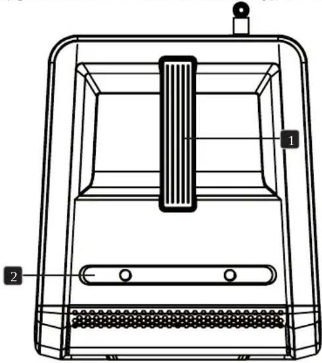
There is an ergonomically shaped handle 1 on the top of the device for lifting and carrying it. The LDANNY8BACKPACK accessory also gives you the option to carry the speaker on your back like a backpack. The smartphone or tablet tray 2 is also located on the top of the device. The microphone holder (optional LDANNY8MICH accessory) can also be attached to the smartphone/tablet tray.
natural_image
Technical line drawing of a mechanical device with labeled components (no text or symbols present)
Please note: Strong mechanical shocks can damage the housing and internal components Do not expose the speaker to rain or moisture.
ASSEMBLY

DANGER: always place the speaker in a suitable location on a sufficiently stable, level, and horizontal surface. Make sure that the speaker cannot fall, for example, off the edge of a stage (for example, due to vibration). When a stand is used, make sure that it is suitable for the speaker's weight and speaker flange. The stand must be positioned upright (vertically) on solid ground, and the maximum permissible height must not be exceeded. There is a danger of incorrectly assembled and positioned devices falling over or down. This can cause serious injury or death.
CONNECTIONS AND OPERATING/DISPLAY ELEMENTS
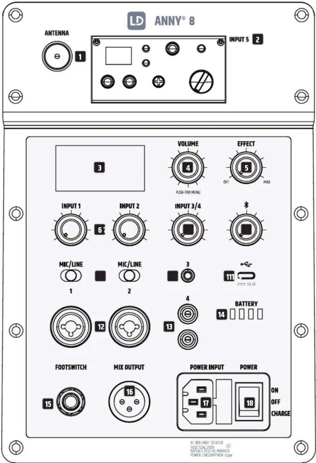
1 ANTENNA (Only available in the HHD or BPH version)
BNC socket for connecting an antenna for the INPUT 5 receiver module (a suitable antenna is included in the receiver module's packaging content).
2 INPUT 5 (Only available in the HHD or BPH version)
Audio input for a receiver module for channel 5. The channel's volume is controlled using the volume control in the receiver module.
3 DISPLAY
Multifunctional graphic LC display for displaying overall volume, speaker and effect presets, and Bluetooth and battery status, as well as input level for channels 1, 2, 3/4, and 5 in the main display. The edit menu displays the menu items, submenu items, and the corresponding edit options. The brightness, contrast, and the power-off for display lighting are adjustable.
4 VOLUME/PUSH FOR MENU
Rotary-push encoder with multiple functions.
- Starting from the main display, the overall volume can be adjusted directly by turning the rotary-push encoder. Turn anticlockwise to decrease volume. Turn clockwise to increase volume.
- Press the rotary-push encoder to access the main menu. Use the rotary-push encoder to navigate in the main menu, turn the encoder to select the desired submenu item, press the encoder to confirm selection, and adjust system settings and change values in the corresponding menu items (see OPERATION; change value or status = turn encoder; confirm value or status change = press encoder).
ATTENTION! High volumes
Set the overall volume to minimum before playing back audio data or before using a microphone, and then only increase the volume slowly to prevent damage to the device or hearing damage caused by sudden high volume levels and feedback.
5 EFFECT
Level control to adjust the sound effect volume (Effect Return). The effect type and the effect sends are set in the device menu under EFFECT.
6 INPUT 1 AND 2 - VOLUME
Level control to adjust the volume for channel 1 or 2. Turn anticlockwise to decrease volume. Turn clockwise to increase volume.
7 INPUT 3/4 - VOLUME
Level control to adjust the volume for channel 3 and 4. Turn anticlockwise to decrease volume. Turn clockwise to increase volume.
8 BLUETOOTH - VOLUME
Level control to adjust the volume for a Bluetooth playback device (for example, smartphone). Turn anticlockwise to decrease volume. Turn clockwise to increase volume (pair Bluetooth playback device, see OPERATION - BLUETOOTH SETTINGS).
INPUT 1 AND 2 - MIC/LINE
Switch to adjust the input sensitivity for channel 1 or 2.
Connection for a microphone: MIC position.
Connection for a playback device with line level: LINE position.
INPUT 3
Unbalanced stereo line input with a 3.5 mm jack socket to connect a playback device (for example, MP3 player). The INPUT 3 and INPUT 4 input sockets are connected in parallel and can be used simultaneously. Any stereo signals that are present are internally summed to mono.
USB-C
USB-C socket to charge a smartphone or tablet
(voltage: 5 volts; maximum charging current: 2 amperes).
INPUT 1 AND 2 - AUDIO INPUT
Audio input for channel 1 or 2, equipped with combo sockets (three-pin XLR/6.3 mm jack).
The audio inputs are suitable for both balanced and unbalanced cabling.
INPUT 4
Unbalanced stereo line input with two cinch sockets to connect playback device
(for example, CD player or keyboard). The INPUT 3 and INPUT 4 input sockets are connected in parallel
and can be used simultaneously. Any stereo signals that are present are internally summed to mono.
BATTERY
Four-segment battery charge status display.
Four illuminated LEDs = 100%, three illuminated LEDs = 75%,
two illuminated LEDs = 50%, one illuminated LED = 25%.
If only the first LED flashes: below 10%.
Please connect the device to the mains supply immediately for charging.
FOOTSWITCH FX ON/OFF
6.3 mm jack socket to connect a footswitch (on/off switch). You can mute and unmute the internal effect module using an external footswitch with a 6.3 mm jack plug.
MIX OUTPUT
Balanced line output with male three-pin XLR socket. The outgoing signal consists of a mix of all input channels plus effect and Bluetooth signals and is separate from the overall volume setting.
POWER INPUT
IEC mains socket with integrated fuse holder. A suitable mains cable is included in the packaging content.
- Use the mains input to operate and charge the internal batteries at the same time by setting the POWER switch to the ON position.
- Use the mains input to charge the internal batteries without operating the device. To do this, set the POWER switch to the CHARGE position.
WARNING: replace the fuse only with a fuse of the same type and same value. Follow the information printed on the housing. In the event of repeated fuse failure, please contact an authorised service centre.
18 POWER
Switch in ON position: device is switched on. The internal batteries can also be charged during operation using the supplied mains cable.
Switch in OFF position: device is switched off.
Switch in CHARGE position: device switched is off and in charging mode.
OPERATION
PLEASE NOTE
As soon as the speaker is switched on (if the battery status is sufficient or if power is supplied via the mains cable), the LD Systems logo briefly appears on the display. All settings (for example, Preset, EQ, and Effect) are loaded as they were set before the speaker was switched off. The speaker is ready for operation after this process.
MAIN DISPLAY
In normal operation, the main display is activated and shows the set overall volume, the activated speaker preset, the effect preset, the input levels for channels 1 to 5, the Bluetooth status and TWS status, and the battery charge status (see diagram).
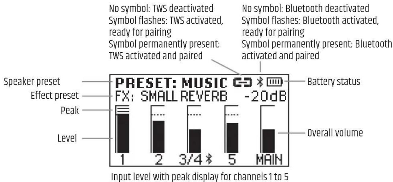
PEAK INDICATOR
A peak symbol in a channel's level display indicates that the corresponding channel's input level is operating above the distortion limit. Reduce the output level of the connected playback device (for example, mixer, keyboard) until the peak symbol is no longer displayed and the speaker plays distortion-free audio signals.
VOLUME
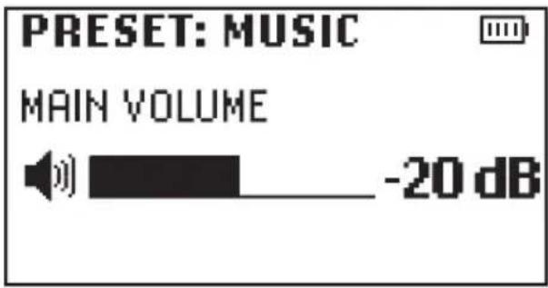
Starting from the main display, the overall volume can be adjusted directly by turning the rotary-push encoder VOLUME / PUSH FOR MENU. The display automatically changes to the corresponding view when the encoder is turned (see diagram below). The main display will automatically be restored after about 10 seconds of inactivity; pressing the encoder switches to the main display immediately.
BLUETOOTH SETTINGS (BLUETOOTH)
Press the rotary-push encoder to access the main menu and then select the menu item BLUETOOTH (coloured background) by turning the encoder. Press the encoder again to access the submenu and select the desired submenu item by turning the encoder. Confirm your entry by pressing the encoder. See the table below for information on the submenu items. In the submenu, select •MAIN MENU and press the encoder to return to the main menu. In the main menu, select •HOME, press the encoder to confirm the selection and return to the main display. The main display will automatically appear after around 10 seconds of inactivity.
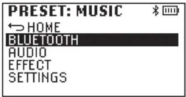
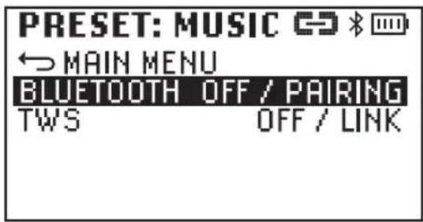
Pairing with a playback device: select BLUETOOTH in the Bluetooth menu, confirm, then select PAIRING, and confirm again. The Bluetooth module is now ready for pairing. The Bluetooth symbol flashes for the duration of pairing. Activate Bluetooth on your playback device (for example, smartphone, tablet) and select ANNY 8 in the Bluetooth menu. Pairing is then completed automatically. As soon as the devices are paired, the Bluetooth symbol is permanently displayed, and PAIRED is displayed in the Bluetooth menu. Audio playback via Bluetooth can now be started.
| BLUETOOTH (change status = turn encoder; confirm status change = press encoder) | ||
| BLUETOOTH Activate Bluetooth PAIRING | ||
| Deactivate Bluetooth OFF | ||
| TWS Activate TWS LINK | ||
| Deactivate TWS OFF | ||
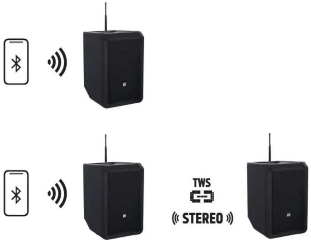
The LD ANNY 8 speaker can be operated in both mono and stereo mode. In mono mode, a stereo signal connected to a stereo input or transmitted via Bluetooth is summed internally in mono. If two ANNY 8 speakers are wirelessly connected with the TWS function, the system paired with the Bluetooth playback device becomes the main unit (stereo left) and the stereo extension becomes the follower unit (stereo right). This means that all stereo signals transmitted via Bluetooth are also played back in stereo without having to connect both speakers via cable. To connect via TWS, simply activate TWS in both units (LINK). The connection will then be automatically established, and LINKED will be displayed in the Bluetooth menu.
PLEASE NOTE:
- Only audio signals from a paired Bluetooth playback device can be transmitted via the TWS stereo link function. Audio signals at the physical input will not be transmitted via TWS.
- After the ANNY 8 speaker has been switched off and back on, the Bluetooth playback device will automatically pair, and the speaker will automatically connect via TWS.
AUDIO SETTINGS (AUDIO)
Press the rotary-push encoder to access the main menu and then select the menu item AUDIO (coloured background) by turning the encoder. Press the encoder again to access the submenu and select the desired submenu item by turning the encoder. Confirm your entry by pressing the encoder. See the table below for information on the submenu items. In the submenu, select •MAIN MENU and press the encoder to return to the main menu. In the main menu, select •HOME, press the encoder to confirm the selection and return to the main display. The main display will automatically appear after around 10 seconds of inactivity.
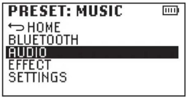
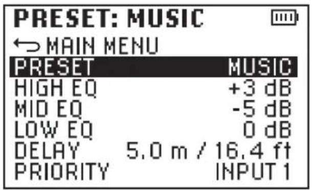
| AUDIO (change value or status = turn encoder, confirm value or status change = press encoder) | ||
| MAIN MENU Back to the main menu | ||
| PRESET Selection of the speaker preset MUSIC | ||
| VOCAL | ||
| LIVE | ||
| ECO | ||
| OFF | ||
| HIGH EQ Setting of the treble frequencies from -12 dB to +12 dB | ||
| MID EQ Setting of the midrange frequencies from -12 dB to +12 dB | ||
| LOW EQ Setting of the bass frequencies from -12 dB to +12 dB | ||
| DELAY Time delay of the sum signal in 0.5 m steps up to 10 m,for example, for a delay line (0 m = OFF, display in metres and feet) | ||
| PRIORITY Priority connection for INPUT 1, 2, or 5 inputs. If an input is assigned priority anda signal is present at this input, the volume of the other inputs is automaticallyreduced. If the signal is no longer present, the volume of the other channelsis raised back to the original value after a few seconds (no multiple selectionpossible,OFF = function deactivated). | INPUT 1 | |
| INPUT 2 | ||
| INPUT 5 | ||
| OFF | ||
EFFECT SETTINGS (EFFECT)
Press the rotary-push encoder to access the main menu and then select the menu item EFFECT (coloured background) by turning the encoder. Press the encoder again to access the submenu and select the desired submenu item by turning the encoder. Confirm your entry by pressing the encoder. See the table below for information on the submenu items. In the submenu, select •MAIN MENU and press the encoder to return to the main menu. In the main menu, select •HOME, press the encoder to confirm the selection and return to the main display. The main display will automatically appear after around 10 seconds of inactivity.

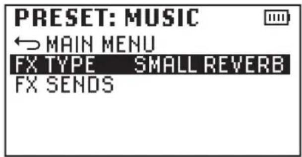
| EFFECT (change value or status = turn encoder; confirm value or status change = press encoder) | |||
| FX TYPE Selection of the effect type or switching-off of the effect (OFF) | SMALL REVERB | ||
| LARGE REVERB | |||
| PLATE REVERB | |||
| DELAY | |||
| OFF | |||
| FX SENDS Set the effect sends for the INPUT 1, 2, and 5 inputs | INPUT 1 0-100% | ||
| INPUT 2 0-100% | |||
| INPUT 5 0-100% | |||
SYSTEM SETTINGS (SETTINGS)
Press the rotary-push encoder to access the main menu and then select the menu item SETTINGS (coloured background) by turning the encoder. Press the encoder again to access the submenu and select the desired submenu item by turning the encoder. Confirm your entry by pressing the encoder. See the table below for information on the submenu items. In the submenu, select •MAIN MENU and press the encoder to return to the main menu. In the main menu, select •HOME, press the encoder to confirm the selection and return to the main display. The main display will automatically appear after around 10 seconds of inactivity.
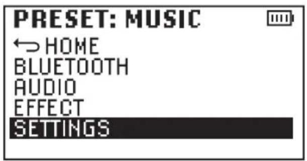
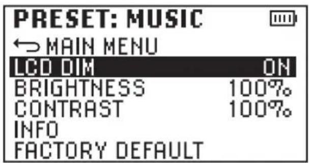
| SETTINGS(change value or status = turn encoder; confirm value or status change = press encoder) | |||
| LCD DIM Display lighting is switched off after around 10 seconds without input | ON | ||
| Display lighting is permanently switched on OFF | |||
| BRIGHTNESS Setting of the display brightness 0-100% 0-100% | |||
| CONTRAST Setting of the contrast 0-100% 0-100% | |||
| NOTE Display of the model name and the device software MODEL: ANNY 8 | |||
| SOFTWARE: 1.x | |||
| FACTORY DEFAULT Reset to factory settings: RESET -> SURE? -> YES | |||
| 2. RESET -> SURE? -> CANCEL | |||
RECEIVER MODULE
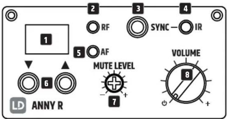
1 LED DISPLAY
The selected radio channel is shown on the display (01–12).
2 LED RF indicator
As soon as there is a radio connection between the transmitter and receiver, the red LED RF indicator lights up.
3 SYNC
Synchronising the receiver and handheld transmitter
To synchronise the radio channel of the receiver and handheld transmitter, select the desired radio channel on the receiver, switch on the handheld transmitter, and then press the SYNC button while pointing the handheld transmitter's infrared interface directly at the receiver's infrared interface. The handheld transmitter's infrared interface is located on the underside of the handheld transmitter. If synchronisation is successful, the red LED RF indicator on the receiver lights up.
Synchronising the receiver and pocket transmitter
To synchronise the radio channel of the receiver and pocket transmitter, select the desired radio channel on the receiver, switch on the pocket transmitter, and then press the SYNC button while pointing the pocket transmitter's infrared interface directly at the receiver's infrared interface. The infrared interface for synchronising the radio channel of the receiver and transmitter is located in the battery compartment. To open the battery compartment, press both markings on the sides of the battery compartment lid at the same time and fold it forward. If synchronisation is successful, the red LED RF indicator on the receiver lights up.
4 IR
Infrared interface to synchronise the radio channel of the receiver and the handheld and/or pocket transmitter.
5 LED AF indicator
The green LED AF indicates that an audio signal is present.
6 ▲ ▼
Select one of the 12 available radio channels by repeatedly pressing the arrow buttons ▲ or ▼.
7 MUTE LEVEL
ATTENTION: set the speaker's volume to a minimum before you change the mute level. The mute function (noise suppression/squelch) prevents noise from occurring when the transmitter is switched off. In addition, sudden noise is suppressed if the signal transmitted from the transmitter to the receiver is not strong enough (for example, the distance between the transmitter and receiver is too great). With the transmitter switched off, use a suitable screwdriver to adjust the mute level so that the background noise is still effectively suppressed (noise suppression is reduced by turning to the left; increased by turning to the right). The transmission range may be reduced under unfavourable circumstances if the setting with strong noise suppression is used. The factory setting for the mute level control is turned all the way to the left, that is, noise suppression is set to the minimum. This setting is suitable for the majority of all applications, and changes are only required in rare cases.
8 VOLUME
Turn the control clockwise past the detent position to switch on the receiver. An additional clockwise rotation increases the volume, and an anticlockwise rotation reduces it. Turn the control anticlockwise past the detent position to switch off the receiver.
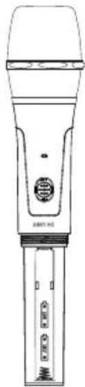
HANDHELD TRANSMITTER

1 ON / OFF
On or off switch. Slide the switch upwards to switch the handheld transmitter on; the word „ON“ can now be read below the switch. Slide the switch downwards to switch the hand-held transmitter off (OFF).
2 STATUS LED
If the charging status of the inserted batteries is sufficient, the LED lights up green when the handheld transmitter is switched on. If the LED lights up red, the charging status is low. Replace the used batteries immediately.
3 IR INTERFACE
The infrared interface for synchronising the radio channel of the receiver and transmitter is located on the underside of the handheld transmitter (for synchronisation procedure, see RECEIVER MODULE - SYNC).
4 SENSITIVITY CONTROL (INPUT SENSITIVITY)
Turn to the left: Decrease the input sensitivity
Turn to the right: Increase the input sensitivity
5 HF SWITCH (SETTING THE TRANSMISSION POWER)
Position „H“: high; Position „L“: low
REPLACING BATTERIES
To replace the batteries, open the handheld transmitter battery compartment lid by turning it anticlockwise and pulling it from the housing. Remove the used batteries and replace with new batteries (2× type AA/LR6, alkaline), following the diagram in the battery compartment. Put the battery compartment lid back and turn it clockwise to close the battery compartment. If the transmitter is not used for a long period, remove the batteries to avoid damage to the transmitter from leaking batteries.

natural_image
Line drawing of a handheld microphone with no visible text or symbols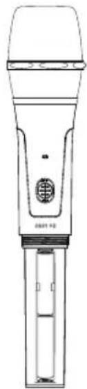
natural_image
Line drawing of a handheld microphone with no visible text or symbols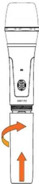
natural_image
Illustration of a handheld device with orange directional arrows indicating rotation or movement (no text or symbols)POCKET TRANSMITTER
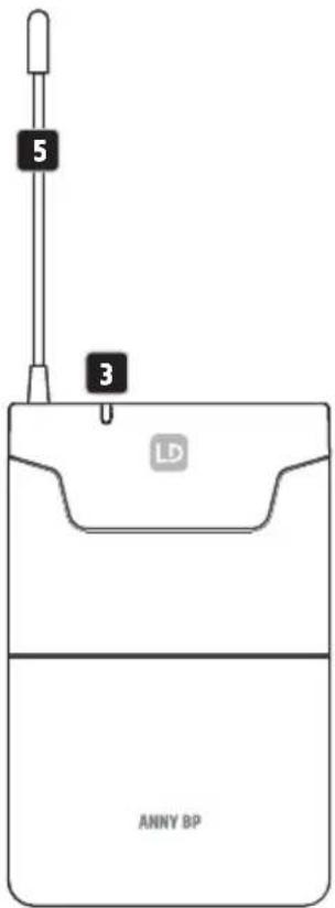
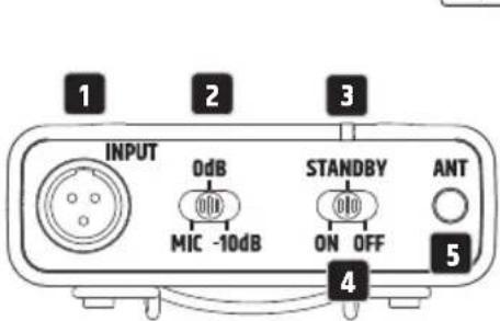
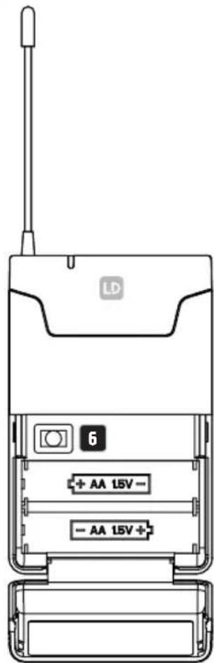
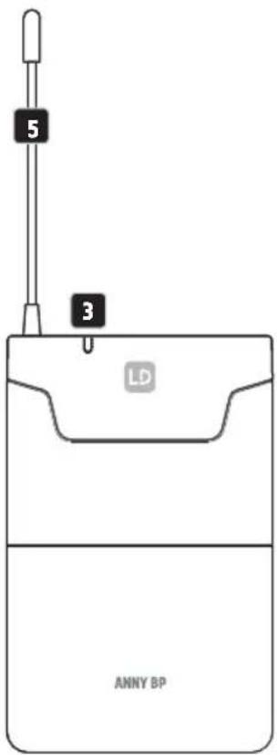
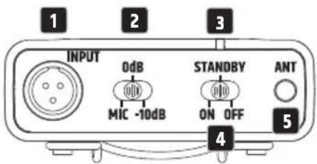
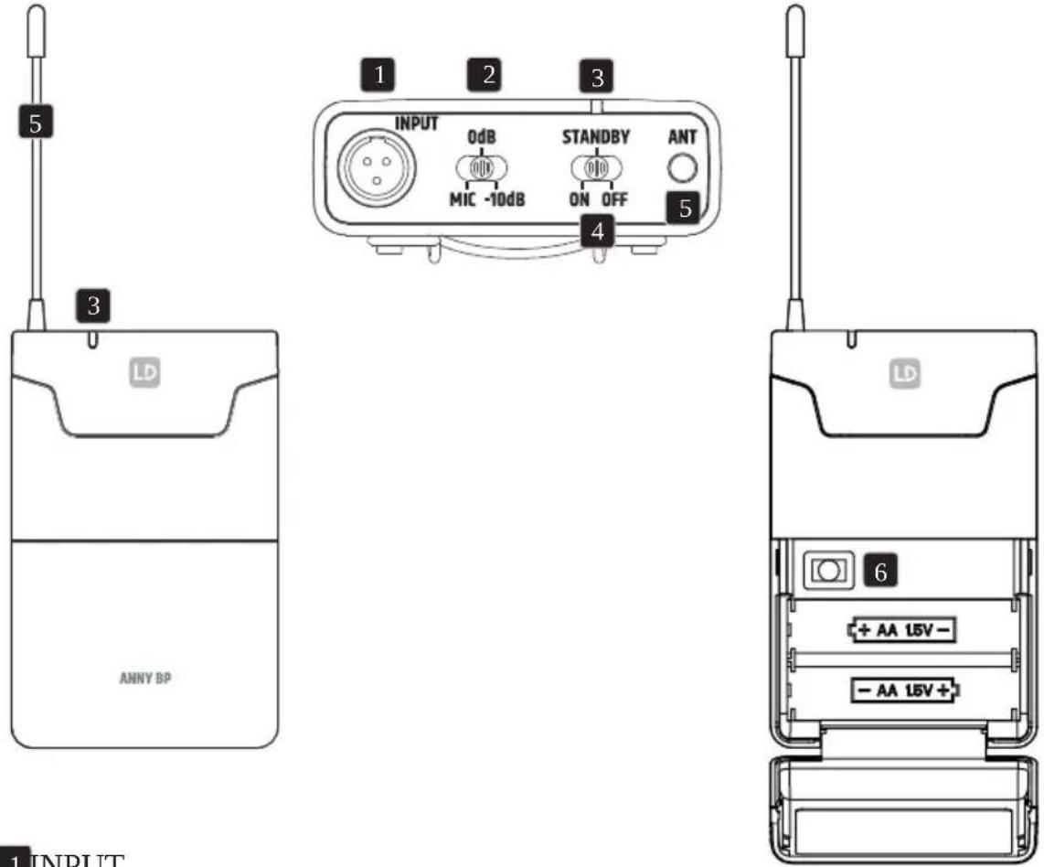
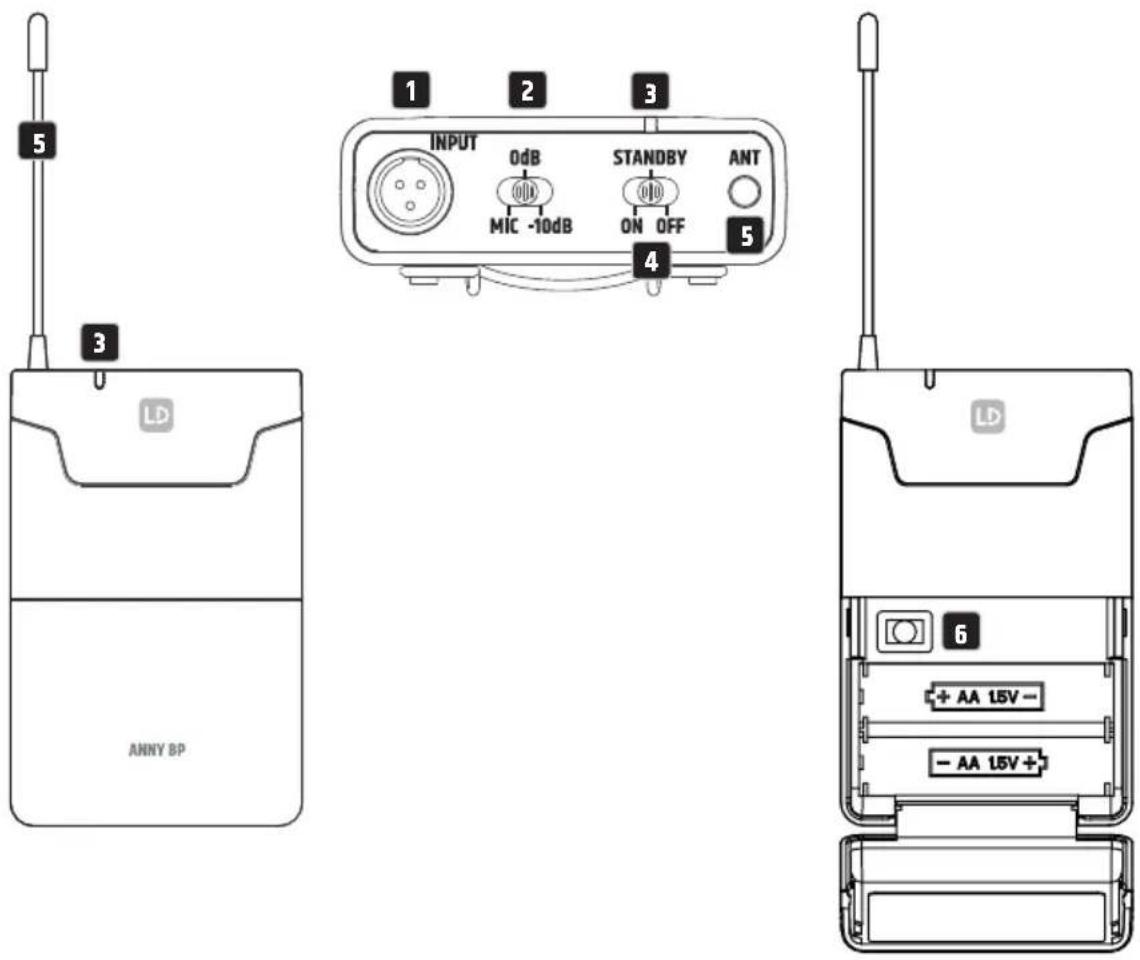
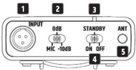
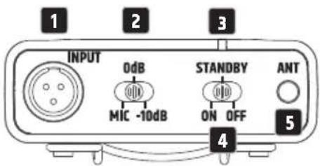
1 INPUT
Three-pin mini XLR socket to connect a headset, lavalier microphone, or instrument microphone an guitar cable.
2 MIC / 0 dB / -10 dB
Adjustment of the input sensitivity. Adjust the sensitivity so that an active signal (for example, speech, vocals, guitar) causes the receiver's green AF LED indicator to light up. As soon as the audio signal starts to distort, reduce the sensitivity on the three-position switch MIC/0 dB/-10 dB to the next lower value (examples: headset = MIC, guitar with passive pickups = 0 dB, guitar with active pickups = -10 dB)
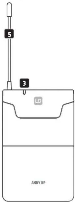
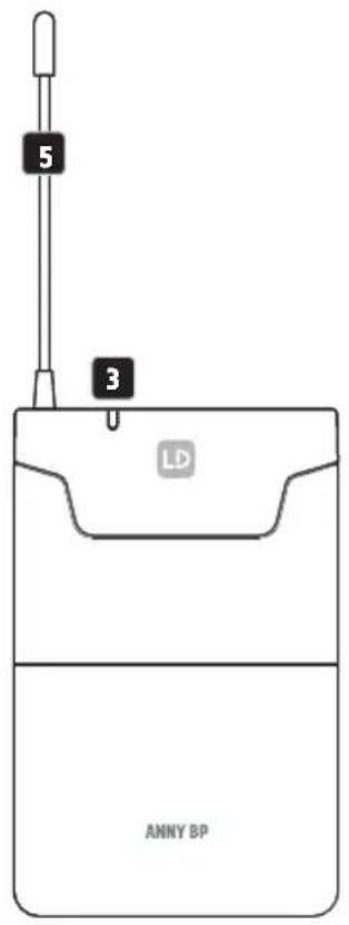
3 STATUS LED
If the charge status of the inserted batteries is sufficient, the LED lights up green when the transmitter is switched on. If the LED lights up red, the charge status is weak. Replace depleted batteries immediately.
4 ON / STANDBY / OFF
Switch to activate or deactivate the pocket transmitter (ON = transmitter is switched on; OFF = transmitter is switched off). In the STANDBY position, the transmitter is in operation, but the audio signal is muted.
5 ANTENNA
Antenna of the pocket transmitter. For optimum reception, do not cover or kink.
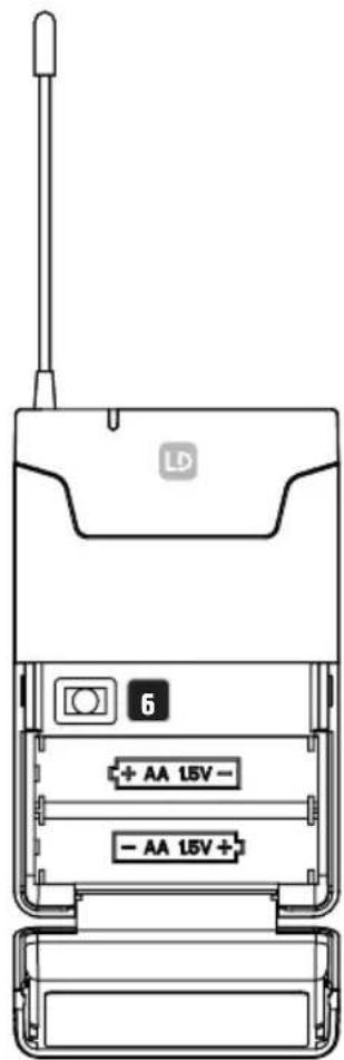
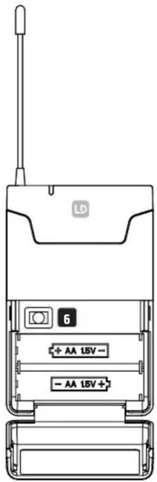
6 IR INTERFACE
The infrared interface for synchronising the radio channel of the receiver and transmitter is located in the battery compartment. To open the battery compartment, press both markings on the sides of the battery compartment lid at the same time and fold it forward (for synchronisation procedure, see RECEIVER MODULE - SYNC).
REPLACING BATTERIES
To replace the batteries, open the pocket transmitter's battery compartment lid by pressing both markings on its sides at the same time and folding it forward. Remove the used batteries and replace with new batteries (2× type AA/LR6, alkaline), following the diagram in the battery compartment. Fold the battery compartment lid back on the housing until it clicks into place. If the transmitter is not used for a long period, remove the batteries to avoid damage to the transmitter from leaking batteries.
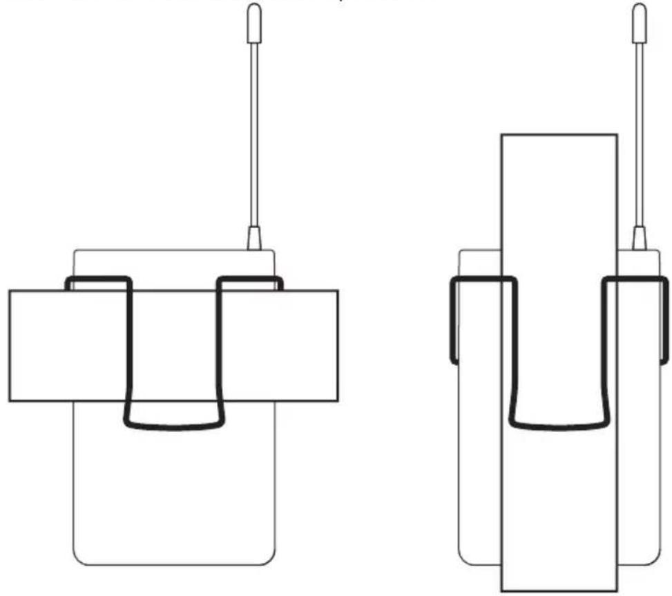
ATTACHING THE POCKET TRANSMITTER
Attach the transmitter to a belt or strap as shown.
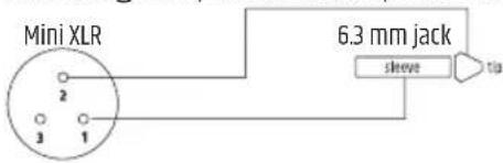
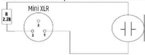
PIN ASSIGNMENT MINI-XLR INPUT
Electric guitar, electric bass, and other high-impedance signal sources
Condenser microphone with internal pull-up resistor

Condenser microphone without internal pull-up resistor
CARE, MAINTENANCE, AND REPAIR
In order to ensure the long-term, proper functioning of the device, it must be regularly cleaned and, if necessary, serviced. The care and maintenance required depends on the intensity of use and the environment in which it is used.
We recommend a visual inspection before each operation. Furthermore, we recommend carrying out all the applicable service measures specified below once every 500 operating hours or, in the case of a lower intensity of use, at the latest after one year. Warranty claims may be limited should defects result from inadequate service and maintenance.
CARE (CARRIED OUT BY USER)
WARNING! Before carrying out any care and maintenance work, the power supply and, if possible, all device connections must be disconnected.

PLEASE NOTE! Improper care can lead to impairment of the device or even destruction.
- Housing surfaces must be cleaned with a clean, damp cloth. Make sure that no moisture can penetrate the device.
- Air inlets and outlets must be regularly cleaned to remove dust and soiling. If compressed air is used, make sure that damage to the device is prevented (for example, fans must be blocked in this case).
- Cables and connectors must be cleaned regularly, and dust and dirt must be removed.
- In general, no cleaning agents and disinfectants or abrasive agents may be used; otherwise, the surface finish may be damaged. Solvents in particular, such as alcohol, can impair the function of housing seals.
- Devices must generally be stored in a dry environment and protected from dust and dirt.
MAINTENANCE AND REPAIR (BY QUALIFIED PERSONNEL ONLY)
DANGER! There are live components in the device. Even after disconnecting from the mains, there may still be residual voltage in the device (for example due to charged capacitors).

PLEASE NOTE! There are no user-serviceable assemblies in the device.

PLEASE NOTE! Maintenance and repair work may only be carried out by specialist personnel authorised by the manufacturer. If in doubt, consult the manufacturer.

PLEASE NOTE! Improperly performed maintenance work may affect warranty claims.

PLEASE NOTE! For conversion or retrofit kits supplied by the manufacturer, the enclosed installation instructions must be observed.
REPLACING DEVICE BATTERIES
BEFORE replacing the batteries, be sure to carefully read the information on DEVICES WITH USER-SERVICEABLE DISPOSABLE OR RECHARGEABLE BATTERIES in the safety instructions in this user manual!
The battery compartment is located on the underside of the speaker next to the angled surface.
Before replacing the batteries, make sure that the device is disconnected from the power supply and switched off (centre power switch position "OFF" with circle symbol).
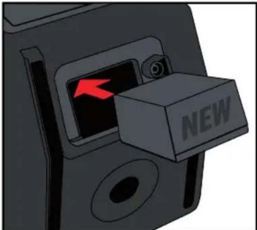
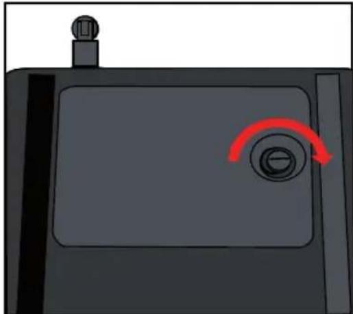
Fold the locking screw's half ring upwards and turn it anticlockwise to open the battery compartment. Fold the battery compartment lid upwards on the screw side and remove it from the battery compartment.
Remove the discharged battery.
natural_image
Illustration of a device with a red arrow pointing to a button labeled 'NEW' (no other text or symbols)Insert a charged battery into the battery compartment.
natural_image
Illustration of a device with a red curved arrow pointing to a circular button (no text or symbols)Insert the lid and its tabs into the corresponding recesses in the battery compartment. Press the lid against the battery compartment and turn the locking screw clockwise to close the battery compartment again. Make sure that the battery compartment is firmly closed before using the device again.
OPTIONAL ACCESSORIES

PLEASE NOTE!
To complete the product numbers for receiver modules, handheld transmitters, and pocket transmitters, the suffix corresponding to the desired frequency range must be added when ordering a product.
The ending B8 corresponds to the frequency range 823–832 MHz + 863–865 MHz
The ending B6 corresponds to the frequency range 655–679 MHz
The ending B5 corresponds to the frequency range 584-608 MHz
The ending B51 corresponds to the frequency range 514–542 MHz (only for the US market)
The ending B47 corresponds to the frequency range 470-490 MHz (only for the US market)
Example: the receiver module with the frequency range 823–832 + 863–865 MHz has the product number LDANNYRB8
Transport rucksack
Product number LDANNY8BACKPACK
Receiver module
Product number LDANNYR
Handheld transmitter
Product number LDANNYMD
Pocket transmitter
Product number LDANNYBP
Microphone holder
Product number LDANNY8MICH
Headset
Product number LDWS100MH1
TECHNICAL DATA
| Product number LDANNY8 | |
| General | |
| Product type Battery-powered PA speaker | |
| Type Active | |
| Colour Stage black Pure white (W) Urban grey (BG) Adventure green (GN) | |
| System output (RMS) 80 W | |
| System output (peak) 160 W | |
| Max. SPL average (sine burst) 110 dB | |
| Max. SPL peak (sine burst) 117 dB | |
| Frequency response (-10 dB) 53 Hz-20 kHz | |
| Crossover frequency 1,800 Hz | |
| Dispersion (H × V) 120° × 60° | |
| Width 249 mm | |
| Depth | 282 mm |
| Height | 390 mm |
| Features | TWS, 5-channel mixer with system presets, three-band EQ, effects (reverb and delay), priority/ducking mode, USB-C port for mobile device charging |
| Weight | 9.04 kg |
| Low/mid woofer | |
| Low/mid woofer dimension | 8" |
| Woofer dimensions (mm) | 203 mm |
| Woofer magnet | Ferrite |
| Woofer brand | Custom-made |
| Woofer voice coil | 1.5" |
| Woofer voice coil (mm) | 38 mm |
| Cabinet construction | Bass reflex |
| Cabinet material | ABS |
HF
Horn Constant directivity
Tweeter dimensions 1"
Tweeter dimensions (mm) 25 mm
Tweeter magnet Ferrite
Tweeter brand Custom-made
Tweeter voice coil 1"
Tweeter voice coil (mm) 25 mm
Amplifier module (integrated)
Amplifier Class D
Protection circuits Short-circuit, over temperature
Ambient temperature (in operation) 0–40°C
Relative humidity 0–80%, non-condensing
Fuse T2AL 250 V
Controls Main VOLUME / menu navigation, INPUT 1 volume, input 1 MIC / LINE switch,
INPUT 2 volume, input 2 MIC / LINE switch, INPUT 3+4 volume, Bluetooth volume, EFFECT, POWER
Indicators Battery status, multifunctional LC display
Power in IEC
Operating voltage 100–240 V, 50/60 Hz
Power consumption 150 W
Physical inputs 5
Physical input connectors 2× 6.3 mm / XLR combo, 2× RCA, 3.5 mm jack
Mix output 1
Mix output connector XLR male
Bluetooth standard 5.0
Bluetooth audio decoder SBC/AAC
Battery
Rechargeable batteries 14.8 V/5,000 mAh
Battery technology Li-ion
Battery indicator Four-segment LED
Battery operation time, music 3.5 h (music preset, full volume)
Battery operation time, music 11 h (eco preset, mid volume)
Product number LDANNY8
| Charging time (80%, no signal) 3 h |
| Charging time (full recharge, no signal) 5 h |
Wireless receiver
| Product type Wireless microphone system accessories | |
| Type Wireless receiver | |
| Transmission frequency range 470–490 MHz (US version) | |
| 512–542 MHz (US version) | |
| 584–608 MHz | |
| 655–679 MHz | |
| 823–832 MHz + 863–865 MHz | |
Modulation type FM
Channels 12
Frequency response 50 Hz–17 kHz
Controls SYNC, mute level (squelch), power/volume, value down, value up
Indicators AF (LED), LED display, RF (LED)
Connections BNC for receiver antenna, audio out
Dynamic handheld microphone
| Transmission frequency range 470–490 MHz (US version) |
| 512–542 MHz (US version) |
| 584–608 MHz |
| 655–679 MHz |
| 823–832 MHz + 863–865 MHz |
Channels 12
Microphone type Dynamic
Directivity Cardioid
Frequency response 100 Hz–12 kHz
Signal-to-noise ratio 104 dB
Rated HF output power 10 mW
Controls Power on/off
Indicators Power/battery status low (LED)
Operating voltage 2× AA battery
Operating time 8 h
Length 250.4 mm
Diameter 32.5 mm (body)
Weight 0.25 kg
Other features Incl. batteries, IR frequency synchronisation
Product number LDANNY8
Bodypack
| Transmission frequency range 470–490 MHz (US version) |
| 512–542 MHz (US version) |
| 584–608 MHz |
| 655–679 MHz |
| 823–832 MHz + 863–865 MHz |
| Channels 12 |
| Inputs Mini XLR (three-pin) |
| Frequency response 45 Hz–20 kHz |
| Signal-to-noise ratio 100 dB |
| Rated HF output power 10 mW |
| Controls Power on / standby / off, gain switch |
| Indicators Power/battery status low (LED) |
| Operating voltage 2× AA battery |
| Operating time 8 h |
| Width 64 mm |
| Height 100 mm (without antenna) |
| Depth 21 mm (without belt clip) |
| Weight 0.15 kg |
| Other features IR frequency synchronisation, switchable gain, standby mode, incl.batteries |
Headset
| Product type | Wireless microphone system accessories |
| Type | Headset |
| Frequency response 100 Hz-12 kHz | |
| Directivity | Cardioid |
| Nominal impedance 680 Ohm | |
| Phantom power requirements 5 V | |
| Microphone input | Mini XLR (three-pin, female) |
| Accessories (included) | Foam windscreen |
| Weight 0.049 kg |
DISPOSAL

Packaging:
- Packaging can be fed into the reusable material cycle using the usual disposal methods.
- Please separate the packaging in accordance with the disposal laws and recycling regulations in your country.
Device:
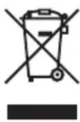
- This device is subject to the European Directive on Waste Electrical and Electronic Equipment, as amended. WEEE Directive Waste Electrical and Electronic Equipment. Waste equipment and batteries do not belong in household waste. Waste equipment and batteries must be disposed of by an authorised waste disposal company or a municipal waste disposal facility. Please observe the applicable regulations in your country!
- Observe all disposal laws applicable in your country.
- As a private customer, you can obtain information on environmentally friendly disposal options from the seller of the product or the appropriate regional authorities.
Disposable and rechargeable batteries:
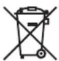
- Disposable and rechargeable batteries should not be disposed of in household waste. Disposable and rechargeable batteries must be disposed of by an authorised waste disposal company or a municipal waste disposal facility.
- Observe all disposal laws and regulations applicable in your country.
- As a private customer, you can obtain information on environmentally friendly disposal options from the seller of the product or the appropriate regional authorities.
- Devices with disposable and rechargeable batteries that cannot be removed by the user must be taken to a collection point for electrical devices.
MANUFACTURER'S DECLARATIONS
MANUFACTURER'S WARRANTY & LIMITATIONS OF LIABILITY
Adam Hall GmbH, Adam-Hall-Str. 1, D-61267 Neu Anspach / E-mail Info@adamhall.com / +49 (0)6081 / 9419-0.
Our current warranty conditions and limitation of liability can be found at:
https://cdn-shop.adamhall.com/media/pdf/MANUFACTURERS-DECLARATIONS_LD_SYSTEMS.pdf.
Contact your distribution partner for service.
UKCA-CONFORMITY
Hereby, Adam Hall Ltd. declares that this product meets the following guidelines (where applicable) Electrical Equipment (Safety) Regulations 2016
Electromagnetic Compatibility Regulations 2016 (SI 2016/1091)
The Restriction of the Use of Certain Hazardous Substances in Electrical and Electronic Equipment Regulation 2012 (SI 2012/3032)
Radio Equipment Regulations 2017(SI 2016/2015)
UKCA-DECLARATION OF CONFORMITY
Products that are subject to Electrical Equipment(Safety)Regulation 2016, EMC Regulation 2016 or RoHS Regulation can be requested at info@adamhall.com.
Products that are subject to the Radio Equipments Regulations 2017
(SI2017/1206) can be downloaded from www.adamhall.com/compliance/
FCC STATEMENT
This device complies with part 15 of the FCC Rules. Operation is subject to the following two conditions:
-
This device may not cause harmful interference.
-
This device must accept any interference received, including interference that may cause undesired operation.
CAUTION! RF Exposure Information: This equipment complies with FCC radiation exposure limits set forth for an uncontrolled environment. This equipment should be installed and operated with minimum distance 20cm between the radiator and your body.
CAUTION! Any changes or modifications to this device not explicitly approved by the manufacturer could void your authority to operate this equipment.
This equipment has been tested and found to comply with the limits for a Class B digital device, pursuant to part 15 of the FCC Rules. These limits are designed to provide reasonable protection against harmful interference in a residential installation. This equipment generates, uses and can radiate radio frequency energy and, if not installed and used in accordance with the instructions, may cause harmful interference to radio communications. However, there is no guarantee that interference will not occur in a particular installation. If this equipment does cause harmful interference to radio or television reception, which can be determined by turning the equipment off and on, the user is encouraged to try to correct the interference by one or more of the following measures:
- Reorient or relocate the receiving antenna.
- Increase the separation between the equipment and receiver.
- Connect the equipment into an outlet on a circuit different from that to which the receiver is connected to.
- Consult the dealer or an experienced radio/TV technician for help.
ISED STATEMENT
This device contains licence-exempt transmitter(s)/receiver(s) that comply with Innovation, Science and Economic Development Canada's licence-exempt RSS(s). Operation is subject to the following two conditions:
- This device may not cause interference.
- This device must accept any interference, including interference that may cause undesired operation of the device.
The digital apparatus complies with Canadian CAN ICES-003 (B)/NMB-003(B).
This equipment complies with IC RSS-102 radiation exposure limits set forth for an uncontrolled environment. This equipment should be installed and operated with minimum distance 20cm between the radiator and your body.
This device meets the exemption from the routine evaluation limits in section 2.5 of RSS 102 and compliance with RSS 102 RF exposure, users can obtain Canadian information on RF exposure and compliance.
RF EXPOSURE INFORMATION
This equipment complies with FCC radiation exposure limits set forth for an uncontrolled environment. This equipment should be installed and operated with minimum distance 20cm between the radiator and your body.
CE CONFORMITY
Adam Hall GmbH hereby confirm that this product meets the following guidelines (where applicable): R&TTE (1999/5/EC) or RED (2014/53/EU) as of June 2017.
Low Voltage Directive (2014/35/EU)
EMC Directive (2014/30/EU)
RoHS (2011/65/EU)
The complete Declaration of Conformity can be found at www.adamhall.com.
Furthermore, you can also request it at info@adamhall.com.
CE DECLARATION OF CONFORMITY
Declarations of conformity for products subject to the LVD, EMC, RoHS Directive can be requested from info@adamhall.com.
Declarations of conformity for products subject to RED Directive can be downloaded from www.adamhall.com/compliance/.
Subject to misprints and errors, as well as technical or other modifications!
natural_image
Technical line drawing of a mechanical device with labeled components (no text or symbols present)
HINWEIS:
1 LED DISPLAY
natural_image
Line drawing of a handheld microphone with control knobs and a speaker grille (no text or symbols)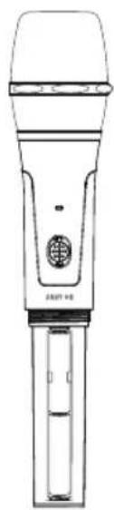
natural_image
Line drawing of a handheld microphone with a small screen and handle (no text or symbols)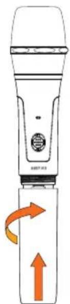
natural_image
Illustration of a handheld device with orange directional arrows indicating rotation or movement (no text or symbols)TASCHENSENDER

1 INPUT
natural_image
Pure mechanical component diagrams without any text, numbers, or symbolsPINBELEGUNG MINI-XLR-EINGANG
natural_image
Illustration of a device with a red curved arrow on the screen (no text or symbols)natural_image
Illustration of a floppy disk with a red arrow indicating a directional change (no text or symbols present)natural_image
Illustration of a device with a red arrow pointing to a button labeled 'NEW' (no other text or symbols)natural_image
Illustration of a device with a red curved arrow pointing to a circular button (no text or symbols)823–832 MHz + 863–865 MHz
Kanäle 12
natural_image
Technical line drawing of a mechanical device with labeled parts (1 and 2), no readable text or symbols beyond labels
1 ÉCRAN LED
ÉMETTEUR DE POCHE
1 INPUT
natural_image
Two schematic diagrams of mechanical components with no text or symbolsAFFECTATION DES BROCHES ENTRÉE MINI-XLR
natural_image
Illustration of a device with a red circular button and a knob, no text or symbols presentnatural_image
Illustration of a device with a red arrow pointing to a button labeled 'NEW' (no other text or symbols)natural_image
Illustration of a computer mouse with a red arrow indicating the left vent (no text or symbols present)natural_image
Illustration of a device with a red curved arrow indicating rotation or adjustment (no text or symbols)Micro-casque (headset)
Micro-casque (headset)
DÉCLARATION DE CONFORMITÉ CE
natural_image
Technical line drawing of a mechanical device with labeled components (no text or symbols present)
9 INPUT 1 Y 2 (MIC/LINE)
15 FOOTSWITCH (FX ON/OFF)
NOTA:
1 PANTALLA LED
TRANSMISOR DE PETACA
1 INPUT
natural_image
Two schematic diagrams of mechanical components with no text or symbolsnatural_image
Illustration of a device with a red arrow pointing to a button labeled 'NEW' (no other text or symbols)natural_image
Illustration of a device with a red curved arrow pointing to a circular button (no text or symbols)Indicadores LED AF (led), pantalla LED, RF (led)
https://cdn-shop.adamhall.com/media/pdf/MANUFACTURERS-DECLARATIONS_LD_SYSTEMS.pdf.
natural_image
Technical line drawing of a mechanical device with labeled components (no text or symbols present)
6 INPUT 1 I 2 - VOLUME
7 INPUT 3/4 - VOLUME
UWAGA:
1 WYŚWIETLACZ LED
NADAJNIK BODYPACK
1 INPUT
natural_image
Two schematic diagrams of mechanical components with no text or symbolsPRZYPISANIE PINÓW WEJŚCIE MINI-XLR
natural_image
Illustration of a black electronic device with a red circular button and antenna (no text or symbols)natural_image
Illustration of a black remote control device with a red arrow indicating left vent (no text or symbols)natural_image
Illustration of a black hard drive with a red arrow indicating left vent, labeled 'NEW' (no other text or symbols)natural_image
Illustration of a device with a red curved arrow indicating rotation or adjustment (no text or symbols)natural_image
Technical line drawing of a rectangular device with internal components and labeled parts (no text or symbols beyond labels)
6 INPUT 1 E 2 - VOLUME
7 INPUT 3 E 4 - VOLUME
NOTA BENE
1 DISPLAY LED
TRASMETTITORE TASCABILE
1 INPUT
natural_image
Pure mechanical component diagrams without any text, numbers, or symbolsASSEGNAZIONE DEI PIN INGRESSO MINI XLR
natural_image
Illustration of a black electronic device with a red circular button and a knob (no text or symbols)natural_image
Illustration of a mechanical device with a red arrow indicating a directional change, no text or symbols present.natural_image
Illustration of a device with a red arrow pointing to a button labeled 'NEW' (no other text or symbols)natural_image
Illustration of a device with a red curved arrow pointing to a circular button (no text or symbols)

- ANNY® 8
- CONTENTS / INHALTSVERZEICHNIS / CONTENU / CONTENIDO / TREŚĆ / CONTENUTO
- ENGLISH
- DEUTSCH
- INFORMATION ON THIS USER MANUAL
- INTENDED USE
- DEFINITIONS AND SYMBOL EXPLANATIONS
- SAFETY INSTRUCTIONS
- DANGER:
- WARNING:
- ATTENTION:
- CAUTION:
- ATTENTION: HIGH-VOLUME AUDIO PRODUCTS!
- RADIO SIGNAL TRANSMISSION (for example, W-DMX or audio radio systems, Bluetooth):
- BATTERY DEVICES AND CHARGERS
- DEVICES WITH USER-SERVICEABLE DISPOSABLE OR RECHARGEABLE BATTERIES DANGER:
- CHARGING, USING, AND STORING BATTERIES
- NOTES FOR PORTABLE INDOOR DEVICES
- PACKAGING CONTENT
- FEATURES
- TRANSPORT HANDLE AND SMARTPHONE/TABLET TRAY
- ASSEMBLY
- ANTENNA (Only available in the HHD or BPH version)
- INPUT 5 (Only available in the HHD or BPH version)
- DISPLAY
- VOLUME/PUSH FOR MENU
- ATTENTION! High volumes
- EFFECT
- INPUT 1 AND 2 - VOLUME
- INPUT 3/4 - VOLUME
- BLUETOOTH - VOLUME
- INPUT 1 AND 2 - MIC/LINE
- INPUT 3
- USB-C
- INPUT 1 AND 2 - AUDIO INPUT
- INPUT 4
- BATTERY
- FOOTSWITCH FX ON/OFF
- MIX OUTPUT
- POWER INPUT
- POWER
- OPERATION
- PLEASE NOTE
- MAIN DISPLAY
- PEAK INDICATOR
- VOLUME
- BLUETOOTH SETTINGS (BLUETOOTH)
- PLEASE NOTE:
- AUDIO SETTINGS (AUDIO)
- EFFECT SETTINGS (EFFECT)
- SYSTEM SETTINGS (SETTINGS)
- RECEIVER MODULE
- LED DISPLAY
- LED RF indicator
- SYNC
- Synchronising the receiver and handheld transmitter
- Synchronising the receiver and pocket transmitter
- IR
- LED AF indicator
- ▲ ▼
- MUTE LEVEL
- VOLUME
- ON / OFF
- STATUS LED
- IR INTERFACE
- SENSITIVITY CONTROL (INPUT SENSITIVITY)
- HF SWITCH (SETTING THE TRANSMISSION POWER)
- REPLACING BATTERIES
- INPUT
- MIC / 0 dB / -10 dB
- STATUS LED
- ON / STANDBY / OFF
- ANTENNA
- IR INTERFACE
- ATTACHING THE POCKET TRANSMITTER
- PIN ASSIGNMENT MINI-XLR INPUT
- CARE, MAINTENANCE, AND REPAIR
- CARE (CARRIED OUT BY USER)
- MAINTENANCE AND REPAIR (BY QUALIFIED PERSONNEL ONLY)
- REPLACING DEVICE BATTERIES
- OPTIONAL ACCESSORIES
- PLEASE NOTE!
- Transport rucksack
- Handheld transmitter
- Pocket transmitter
- Microphone holder
- Headset
- HF
- Amplifier module (integrated)
- Product number LDANNY8
- DISPOSAL
- Packaging:
- Device:
- Disposable and rechargeable batteries:
- MANUFACTURER'S DECLARATIONS
- MANUFACTURER'S WARRANTY & LIMITATIONS OF LIABILITY
- UKCA-CONFORMITY
- UKCA-DECLARATION OF CONFORMITY
- FCC STATEMENT
- ISED STATEMENT
- RF EXPOSURE INFORMATION
- CE CONFORMITY
- CE DECLARATION OF CONFORMITY
- HINWEIS:
- TASCHENSENDER
- PINBELEGUNG MINI-XLR-EINGANG
- ÉCRAN LED
- AFFECTATION DES BROCHES ENTRÉE MINI-XLR
- Micro-casque (headset)
- DÉCLARATION DE CONFORMITÉ CE
- INPUT 1 Y 2 (MIC/LINE)
- FOOTSWITCH (FX ON/OFF)
- NOTA:
- PANTALLA LED
- UWAGA:
- WYŚWIETLACZ LED
- PRZYPISANIE PINÓW WEJŚCIE MINI-XLR
- INPUT 1 E 2 - VOLUME
- INPUT 3 E 4 - VOLUME
- NOTA BENE
- DISPLAY LED
- ASSEGNAZIONE DEI PIN INGRESSO MINI XLR
Brand : LD Systems
Model : ANNY 8
Category : Loudspeaker