JJS-E1P - Sander MSW - Free user manual and instructions
Find the device manual for free JJS-E1P MSW in PDF.


| Product type | Dovetail jig |
| Brand | MSW |
| Model | JJS-E1P |
| Usage | Creating dovetail joints for wood assemblies |
| Dimensions (L x D x H) | 440 x 280 x 140 mm |
| Total length | 300 mm |
| Weight | 7.9 kg |
| Compatible workpiece thickness | 8 – 32 mm |
| Router bit diameter | 6.4 x 12.8 x 15 mm |
| Power supply required | Electric router (not included, recommended 1200 W, 230 V) |
| Recommended router speed | 13,700 – 30,000 rpm |
| Maximum plunge depth of router | 50 mm |
| Recommended collet sizes | 6.35 mm and 8 mm |
| Safety | Use PPE (safety glasses, hearing protection, gloves); stable surface; disconnect the tool before adjustments |
| Maintenance | Clean with a soft non-abrasive cloth; store in a dry and cool place |
| Repairs | Entrust to the manufacturer's service center; use original parts |
| Spare parts | Available from the manufacturer |
| Maintenance interval | Inspect regularly before each use |
| Operating conditions | Indoors only, well-ventilated area |
| Compliance | Designed according to strict technical guidelines |
Frequently Asked Questions - JJS-E1P MSW
User questions about JJS-E1P MSW
0 question about this device. Answer the ones you know or ask your own.
Ask a new question about this device
Download the instructions for your Sander in PDF format for free! Find your manual JJS-E1P - MSW and take your electronic device back in hand. On this page are published all the documents necessary for the use of your device. JJS-E1P by MSW.
USER MANUAL JJS-E1P MSW
natural_image
Close-up of a mechanical component with a white arrow pointing to a specific feature on a metallic surface (no text or symbols visible)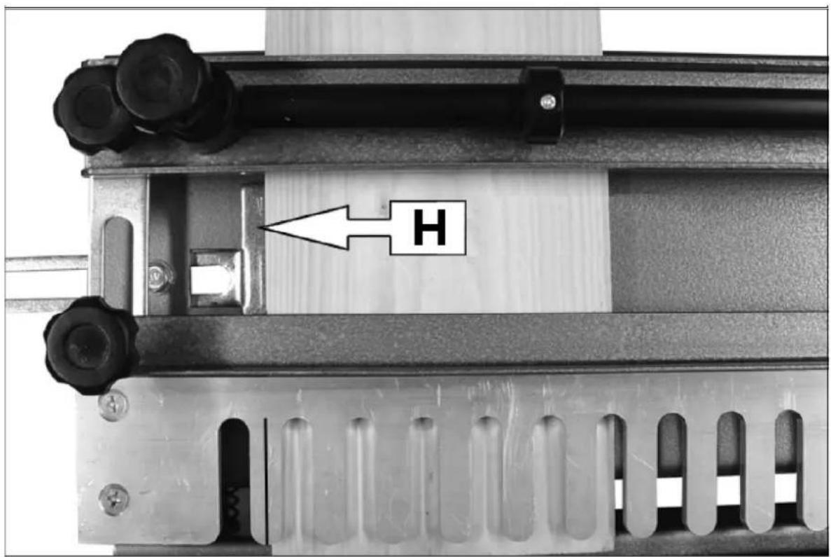
natural_image
Exterior view of a wooden beam joint (no text or symbols visible)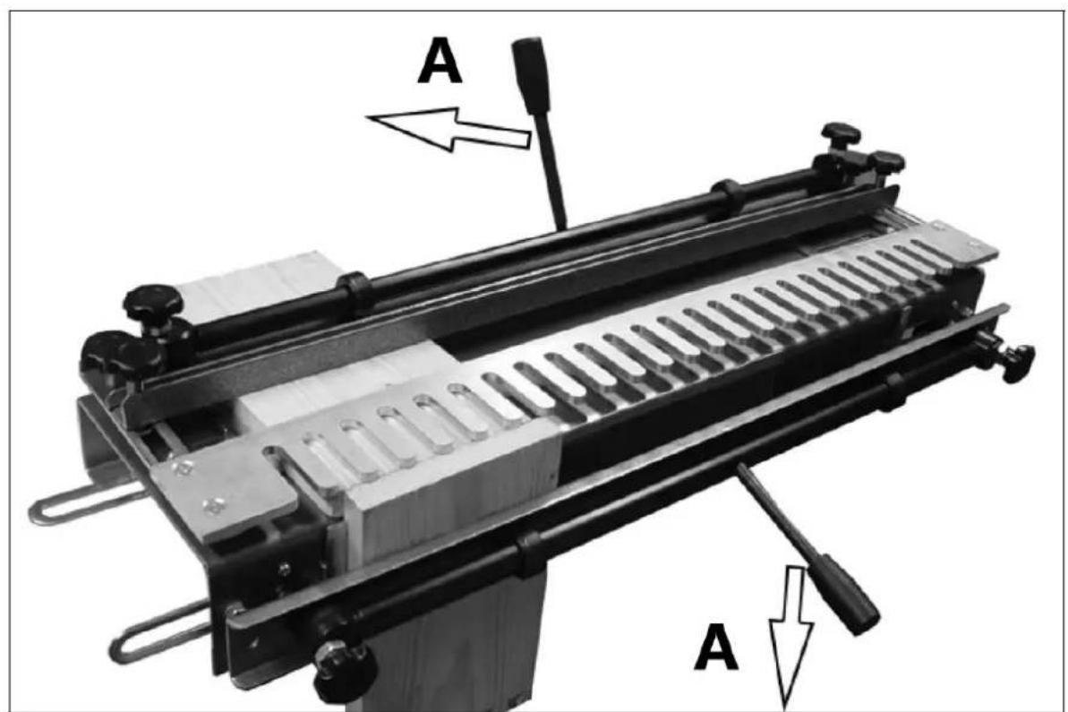
A - sperren
This User Manual has been translated for your convenience using machine translation. Reasonable efforts have been made to provide an accurate translation; however, no automated translation is perfect nor is it intended to replace human translators. The official User Manual is the English version. Any discrepancies or differences created in the translation are not binding and have no legal effect for compliance or enforcement purposes. If any questions arise related to the accuracy of the information contained in the User Manual, please refer to the English version of those contents which is the official version.
Technical data
| Parameter description | Parameter value | |
| Product name | Dovetail jointer | Dovetail jointer |
| Model | MSW-JJS-E1K | MSW-JJS-E1P |
| Milling machine drill bit [mm] | 6,4 x 12,8 x 15 | 6,4 x 12,8 x 15 |
| Workpiece thickness [mm] | 8-32 | 8-32 |
| Total length [mm] | 600 | 300 |
| Dimensions (width x depth x height) mm] | 740 x 270 x 140 | 440 x 280 x 140 |
| Weight [kg] | 13 | 7.9 kg |
1. General description
The user manual is designed to assist in the safe and trouble-free use of the device. The product is designed and manufactured in accordance with strict technical guidelines, using state-of-the-art technologies and components. Additionally, it is produced in compliance with the most stringent quality standards.
DO NOT USE THE DEVICE UNLESS YOU HAVE THOROUGHLY READ AND UNDERSTOOD THIS USER MANUAL.
To increase the product life of the device and to ensure trouble-free operation, use it in accordance with this user manual and regularly perform maintenance tasks. The technical data and specifications in this user manual are up to date. The manufacturer reserves the right to make changes associated with quality improvement. The device is designed to reduce noise emission risks to a minimum, taking into account technological progress and noise reduction opportunities.
Legend

Read instructions before use.

WARNING! or CAUTION! or REMEMBER! Applicable to the given situation. (general warning sign)

Use ear protection. Exposure to loud noise may result in hearing loss.

Wear protective goggles.

Wear protective gloves.

Wear foot protection.
Only use indoors.

PLEASE NOTE! Drawings in this manual are for illustration purposes only and in some details may differ from the actual product.
2. Usage safety

ATTENTION! Read all safety warnings and all instructions. Failure to follow the warnings and instructions may result in serious injury or even death.
The terms "device" or "product" are used in the warnings and instructions to refer to: Dovetail jointer
2.1. Safety in the workplace
a) Make sure the workplace is clean and well lit. A messy or poorly lit workplace may lead to accidents. Try to think ahead, observe what is going on and use common sense when working with the device. The workplace should be dry. Make sure that the floor is not slippery.
b) If you are unsure about whether the product is operating correctly or if you find damage, please contact the manufacturer's service centre.
c) Only the manufacturer's service centre may make repairs to the product. Do not attempt to make repairs yourself!
d) Children or unauthorised persons are forbidden to enter a work station. (A distraction may result in loss of control over the device).
e) Use the device in a well-ventilated space.
f) The device produces dust and debris during operation. It is important to protect bystanders from their harmful effects.
g) Please keep this manual available for future reference. If this device is passed on to a third party, the manual must be passed on with it.
h) Keep packaging elements and small assembly parts in a place not available to children.
i) Keep the device away from children and animals.
j) If this device is used together with another equipment, the remaining instructions for use shall also be followed.

Remember! When using the device, protect children and other bystanders.
2.2. Personal safety
a) Do not use the device when tired, ill or under the influence of alcohol, narcotics or medication which can significantly impair the ability to operate the device.
b) The device is not designed to be handled by persons (including children) with limited mental and sensory functions or persons lacking relevant experience and/or knowledge unless they are supervised by a person responsible for their safety or they have received instruction on how to operate the device.
c) When working with the device, use common sense and stay alert. Temporary loss of concentration while using the device may lead to serious injuries.
d) Use personal protective equipment as required for working with the device, specified in section 1 (Legend). The use of correct and approved personal protective equipment reduces the risk of injury.
e) Do not overestimate your abilities. When using the device, keep your balance and remain stable at all times. This will ensure better control over the device in unexpected situations.
f) The device is not a toy. Children must be supervised to ensure that they do not play with the device.
2.3. Safe device use
a) Do not overload the device. Use the appropriate tools for the given task. A correctly-selected device will perform the task for which it was designed better and in a safer manner.
b) Keep the device in perfect technical condition. Before each use check for general damage and especially check for cracked parts or elements and for any other conditions which may impact the safe operation of the device. If damage is discovered, hand over the device for repair before use.
c) Device repair or maintenance should be carried out by qualified persons, only using original spare parts. This will ensure safe use.
d) To ensure the operational integrity of the device, do not remove factory-fitted guards and do not loosen any screws.
e) When transporting and handling the device between the warehouse and the destination, observe the occupational health and safety principles for manual transport operations which apply in the country where the device will be used.
f) Do not move, adjust or rotate the device in the course of work.
g) Clean the device regularly to prevent stubborn grime from accumulating.
h) The device is not a toy. Cleaning and maintenance may not be carried out by children without supervision by an adult person.
i) It is forbidden to interfere with the structure of the device in order to change its parameters or construction.
j) Keep the device away from sources of fire and heat.
k) Do not overload the device.
I) Using the device, observe the rules given in this manual, and the safety regulations in force at the workplace.
m) The device must not be used outdoors or in wet or humid environment.
n) When working with the device, make sure that bystanders, especially children, stay away from the device and maintain a safe distance.
o) The product must be attached to an even and stable surface.
p) The device is designed to work with a power tool. Disconnect the power tool from the power supply before making any adjustments, repairs, tool changes, and before cleaning the device

ATTENTION! Despite the safe design of the device and its protective features, and despite the use of additional elements protecting the operator, there is still a slight risk of accident or injury when using the device. Stay alert and use common sense when using the device.
3. Use guidelines
The product is intended to create wooden joints in a characteristic shape, which collapse into each other, creating a stable and durable connection.
The user is liable for any damage resulting from unintended use of the device.
3.1. Device description
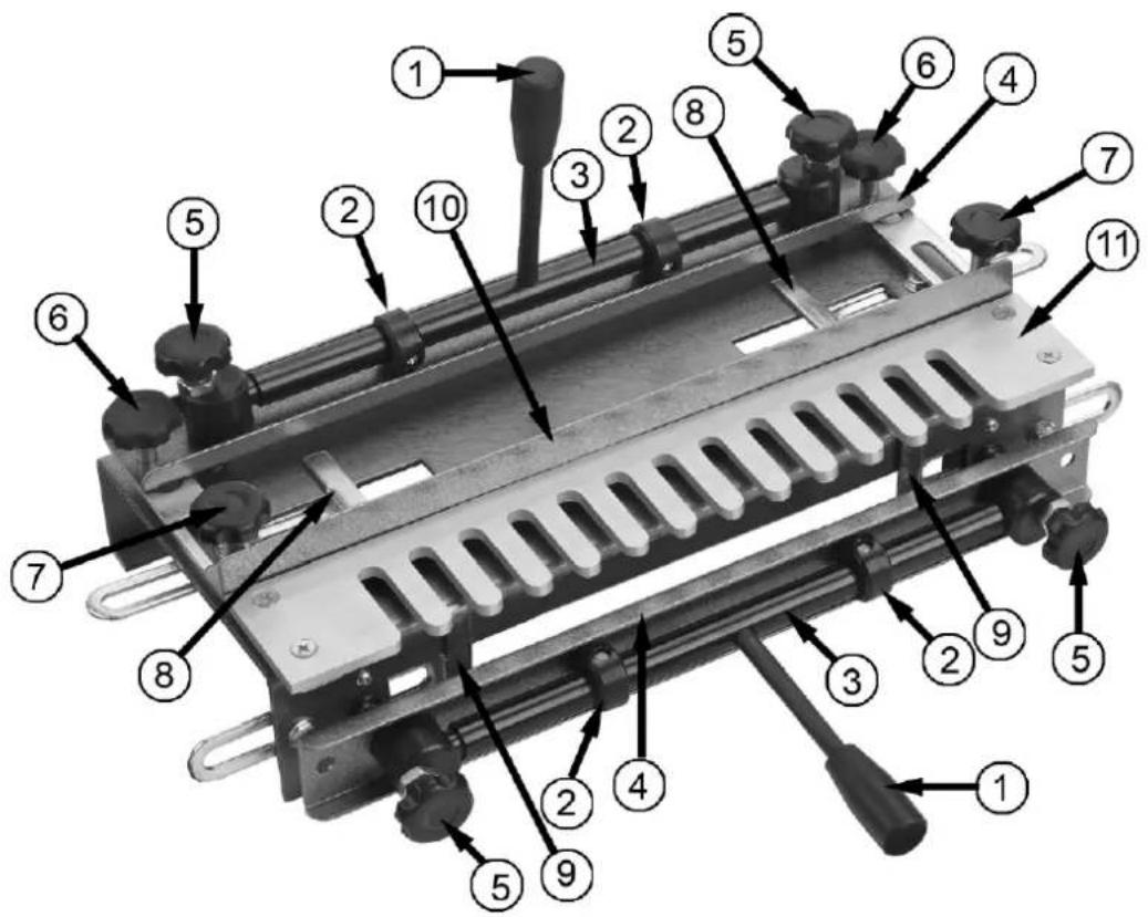
1 - Locking Clamp Handle
2 - Eccentric Cam
3 - Eccentric Shaft
4 - Clamp
5 - Clamp Adjusting Screw
6 - Template Securing Screw
7 - Backstop Locking Screw
8 - Horizontal Stop
9 - Vertical Stop
10 - Backstop
11 - Template
3.2. Preparation for use
Assembling the jig
Screw the front and top handles into the eccentric bars.
- The workpieces will be locked when the top locking clamp handle is pushed away from you and when the lower locking clamp handle is pushed downwards.
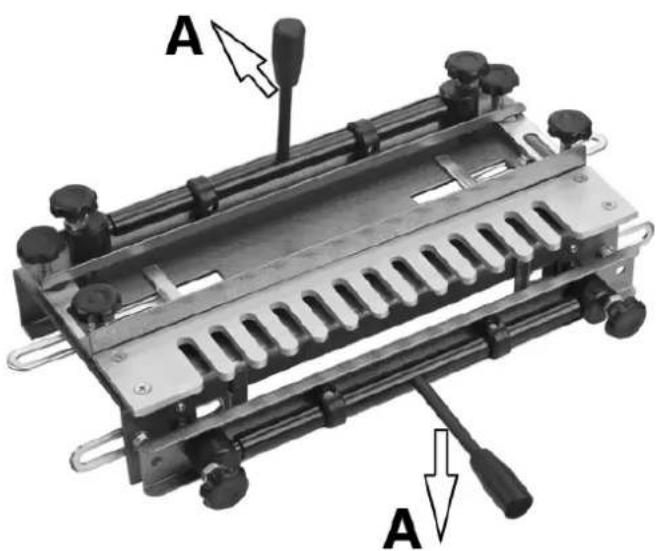
A - lock
Mounting the jig
There are four holes provided in the base for mounting the jig.
Mount the jig to a bench as shown and secure using suitable screws (not supplied).
• The jig must be mounted flush with the front edge of the workbench.
- Make sure there is enough space behind the jig to accommodate the longest length of timber you are likely to work on.
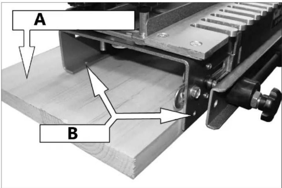
A - Mounting board
B – Secure here
Setting the end stops
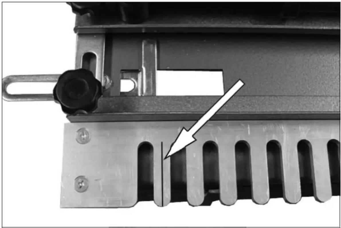
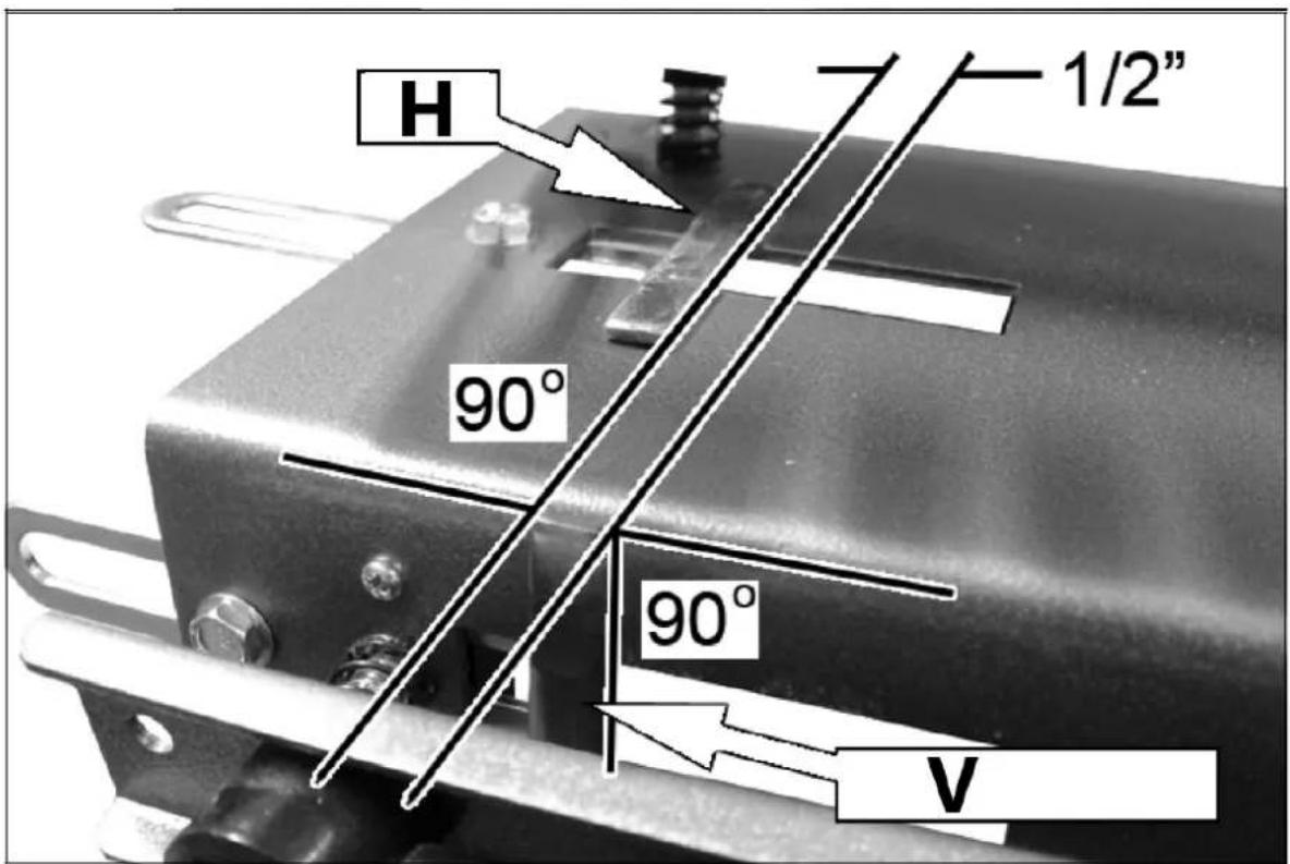
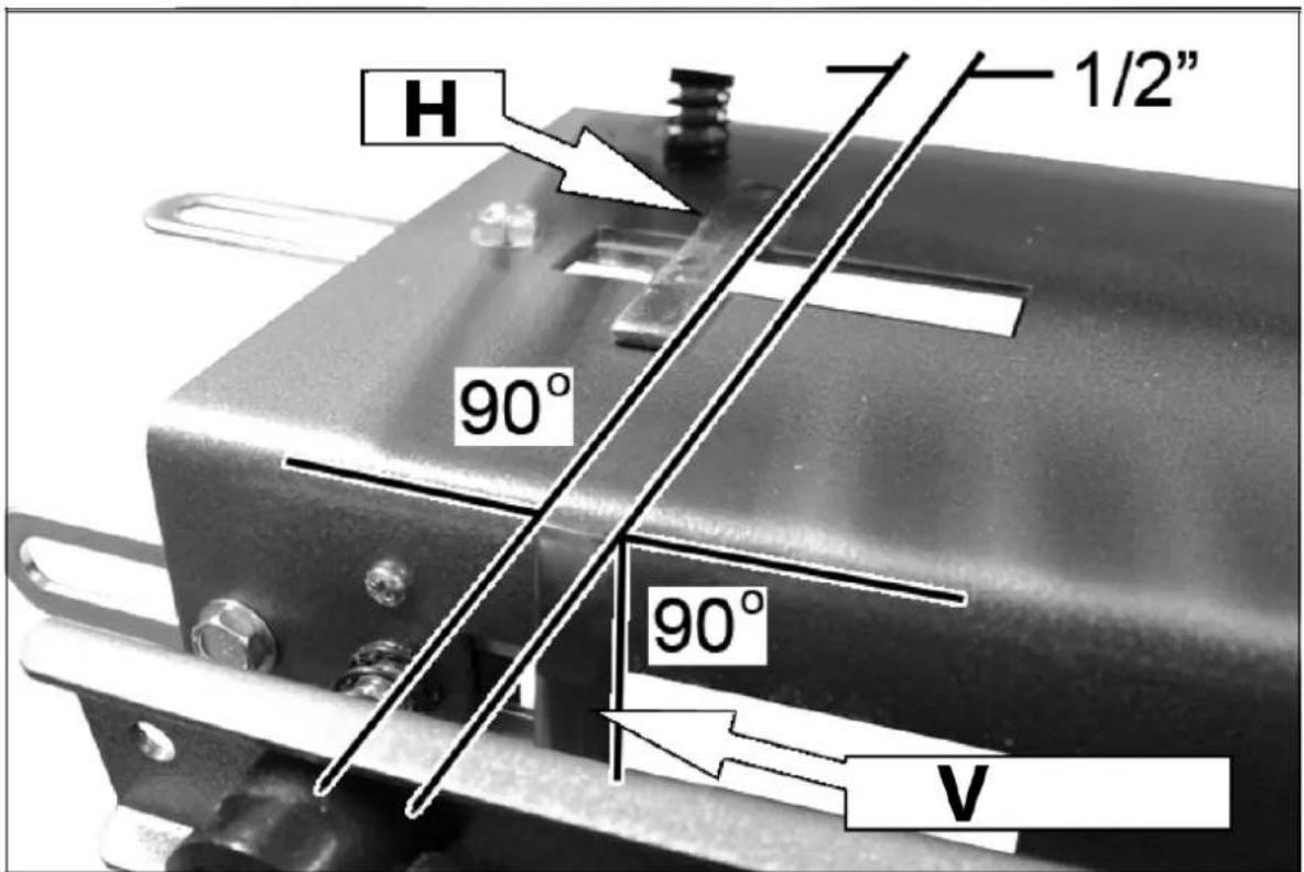
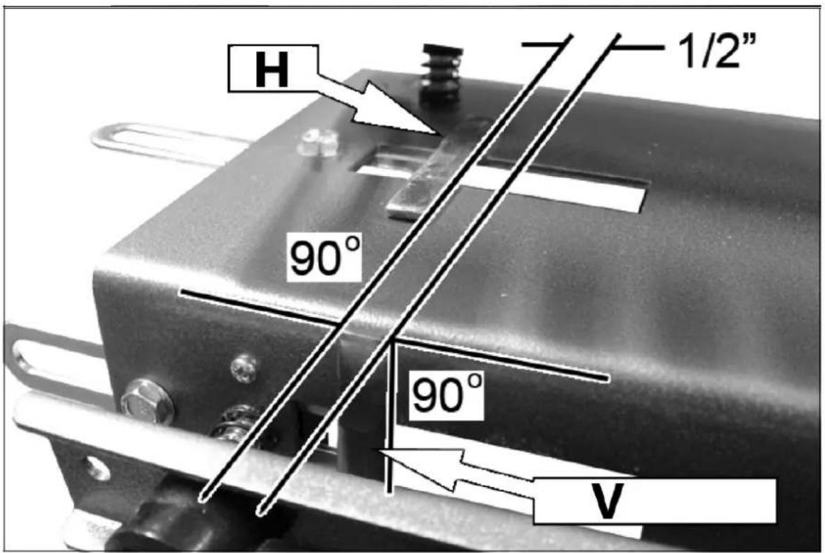
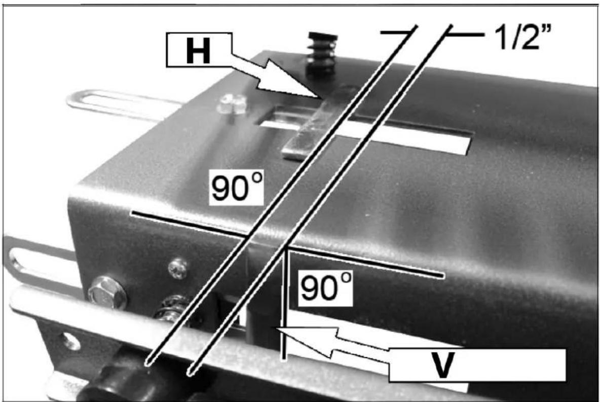
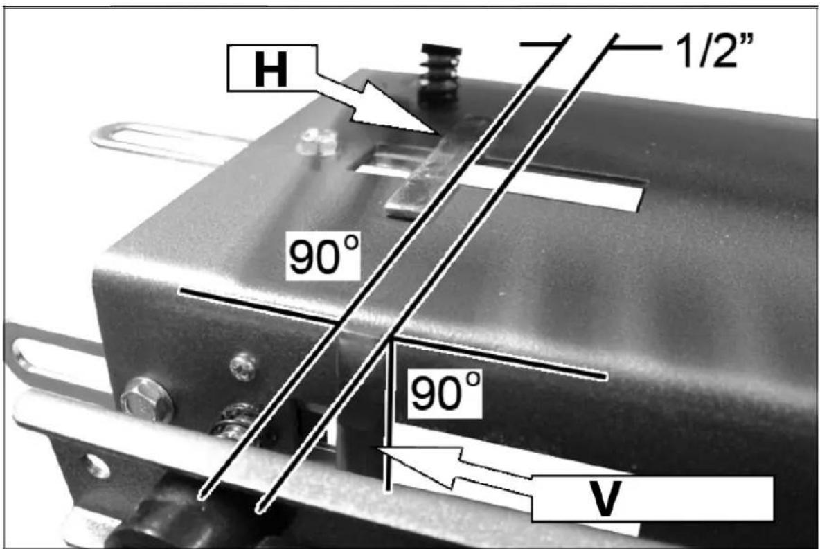
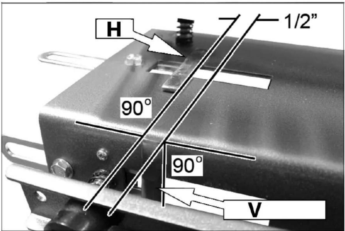
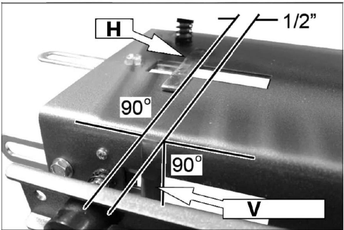
1) Use a set square to draw a pencil line halfway across the first finger of the template.
• The line must be square to the edges of the template.
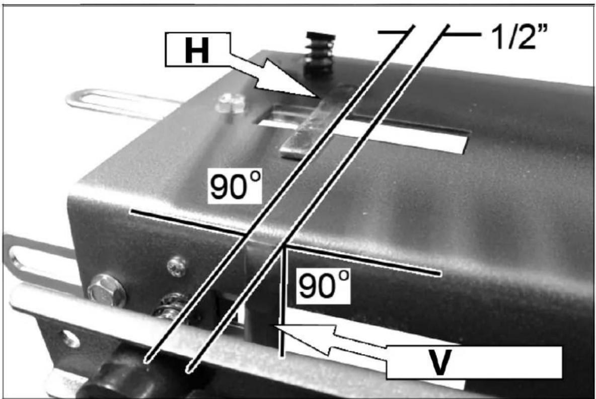
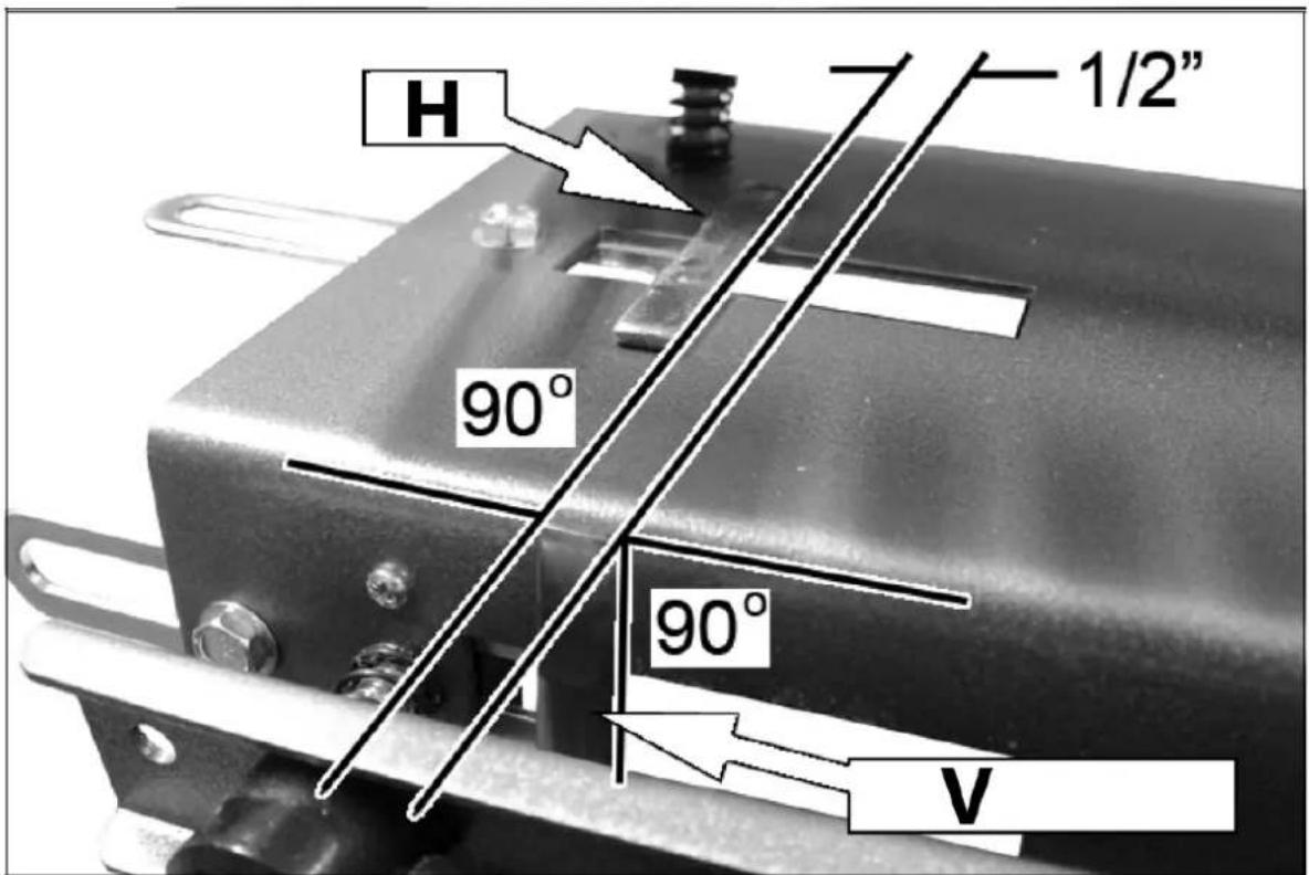
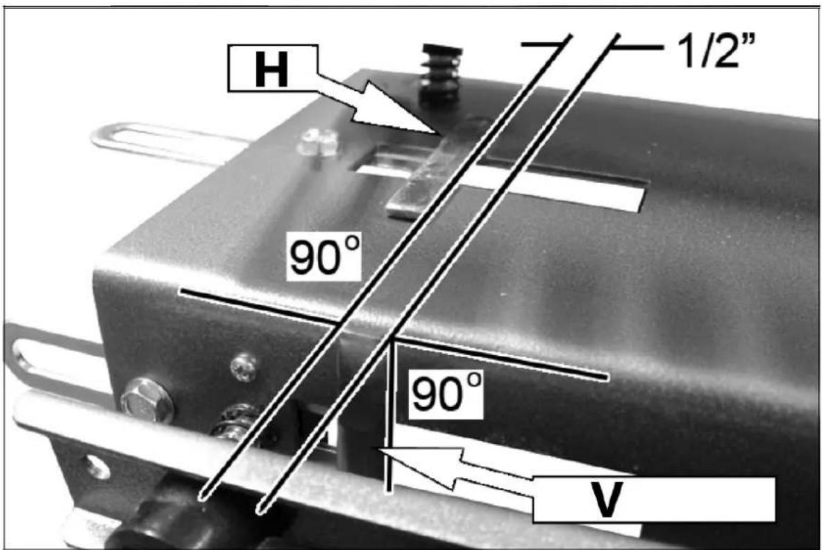
2) Line up the inside edge of the left horizontal stop with the line you just drew on the template.
• Use a set square to ensure the stop is square to the jig.
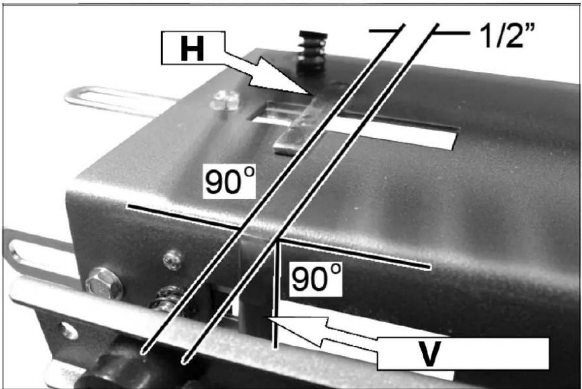
3) Offset the vertical stop 1/2" to the right of the horizontal stop.
- Ensure the vertical stop is square to the top of the jig.
4) Mirror these settings on the right hand side of the jig.
natural_image
Close-up of a mechanical component with a white arrow pointing to a specific feature on a metallic surface (no text or symbols visible)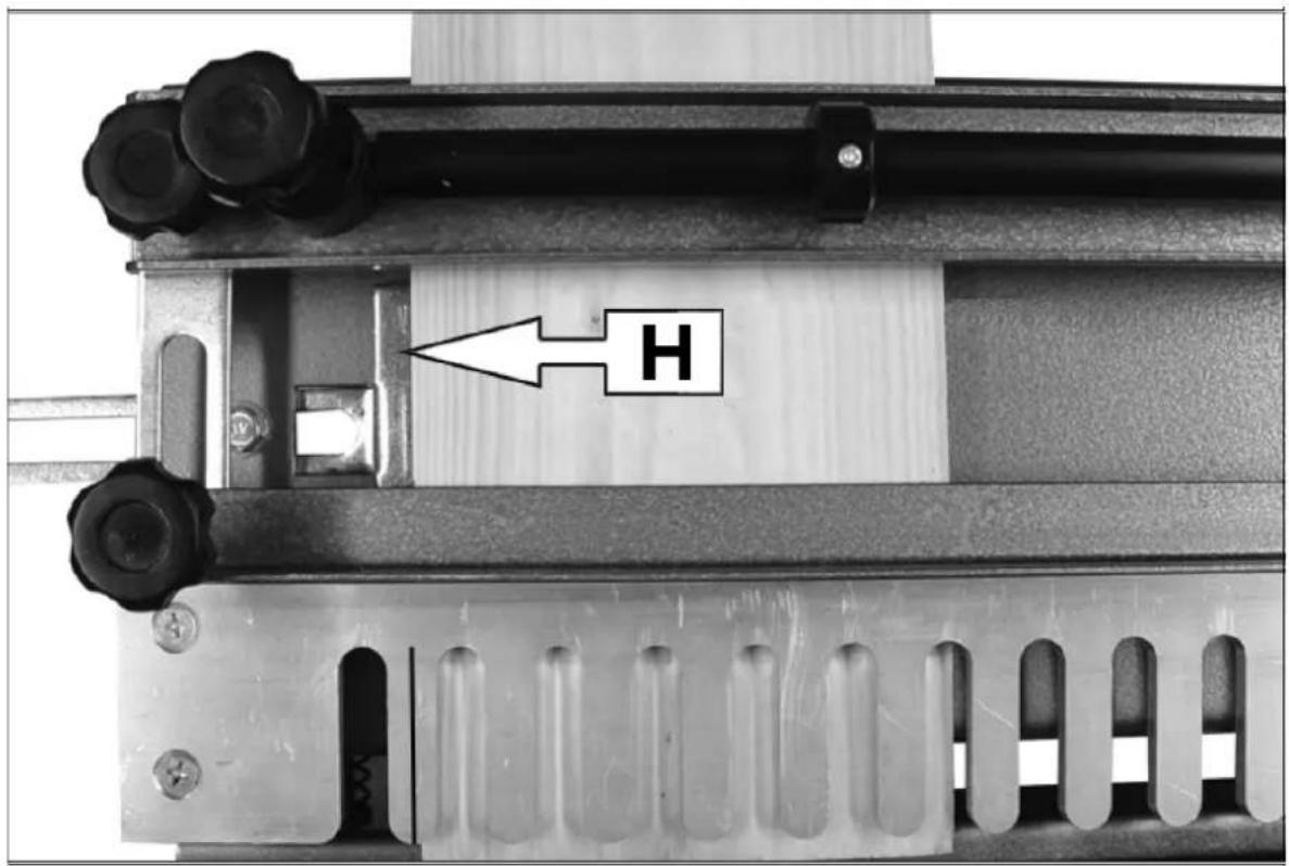
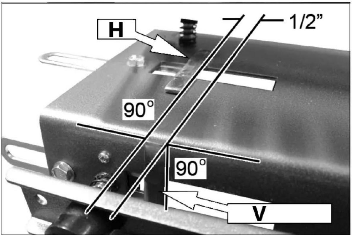
H – Horizontal stop
V - Vertical stop
Placing the timber into the jig
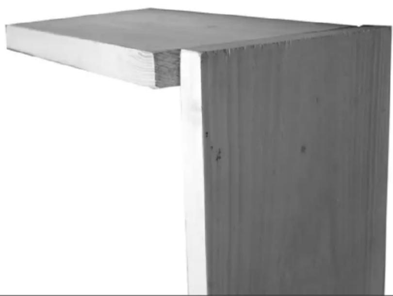
1) Align the timber so that the side of the workpiece is mounted in the front vertical clamp.
- It should extend above the front edge of the jig by the thickness of the piece to be mounted under the top clamp (front or back of the drawer).
2) The piece of timber in the top clamp is then butted up to this, so that both pieces are flush under the template.
3) The two pieces sit in the jig.
- Make sure that both pieces are butted up against the horizontal / vertical stops.
4) Use the locking clamp handles to secure the wood to the jig.
- You may need to adjust the top and front clamp bars to suit the thickness of the timber using the clamp adjusting screws at either end of each clamp bar so that the wood is held firmly in place
- When narrow pieces of wood are being used, place another piece of wood (exactly the same thickness) underneath the clamp bar at the opposite end to ensure an even grip on the wood and to avoid distorting the bars.
natural_image
Close-up of a wooden beam joint or bracket (no text or symbols visible)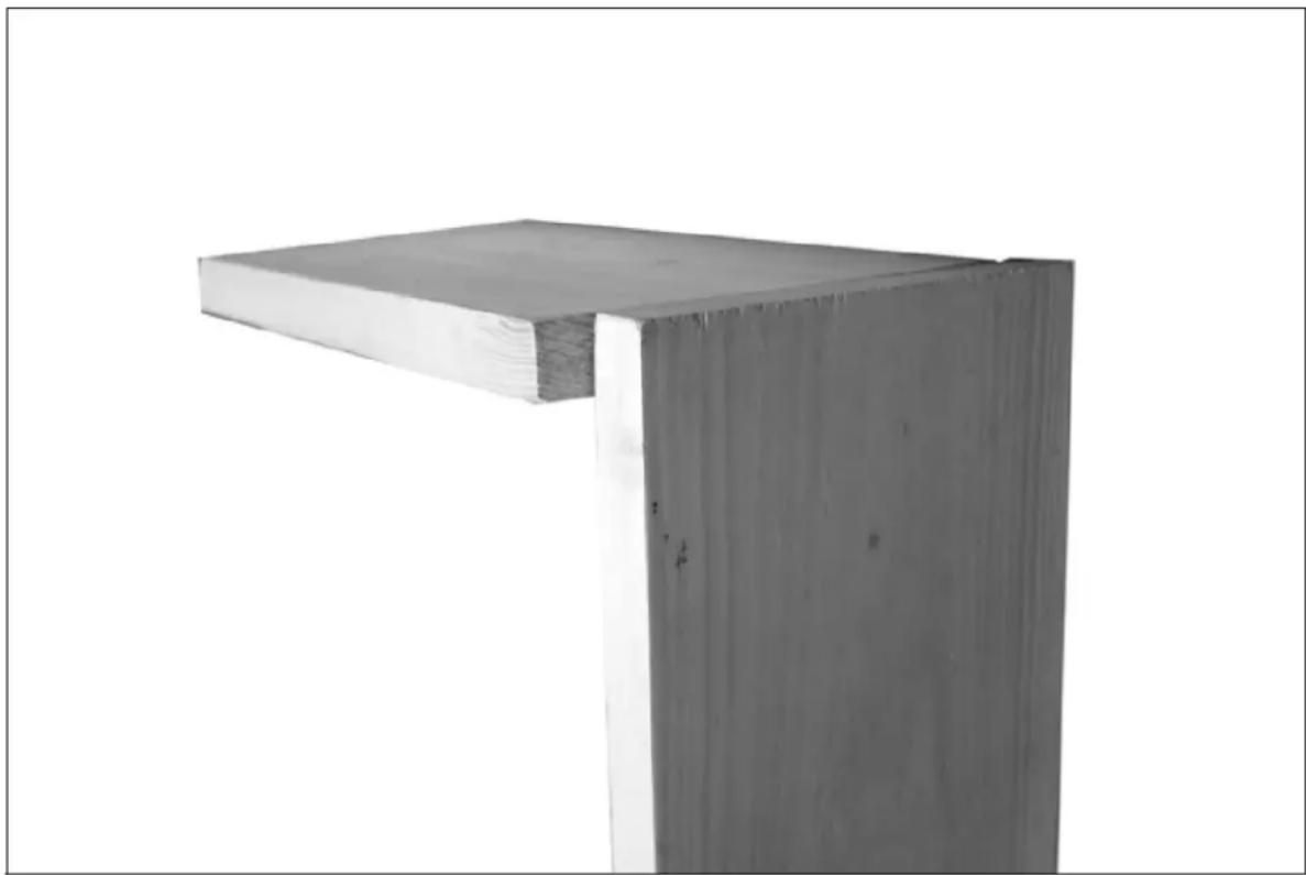
natural_image
Exterior view of a wooden beam joint (no text or symbols visible)
A - lock
Setting the template position
1) Unlock the two template securing screws and position the template so that the tips of the fingers sit 3mm back from the edge of the vertically mounted timber.
2) Lock the template into position using the two template securing screws.
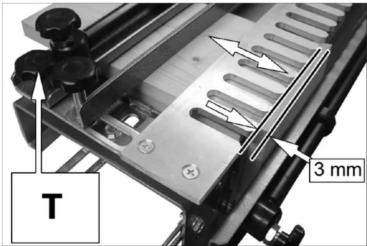
T - Template securing screws
Setting the backstop position
The distance the backstop needs to be positioned from the front of the template fingers depends on the size of router base fitted to your router.
The formula to calculate this is:
$$ \left(\frac {d _ {r}}{2}\right) + (2 \times w) - \left(\frac {d _ {c}}{2}\right) $$
d_r - router base diameter
w - width of the drawer sides
d_c — cutter tip diameter
Example
Using a router which has a base diameter of 160 mm, making a drawer that has sides 18 mm thick and using the standard cutter supplied with a tip diameter of 14.8 mm.
$$ \begin{array}{r l} & \left(\frac {1 6 0 m m}{2}\right) + (2 \times 1 8 m m) - \left(\frac {1 4 . 8 m m}{2}\right) \ & (8 0 m m) + (3 6 m m) - 7. 4 m m) \end{array} $$
Distance = 108.6 mm
The distance from the tips of the template fingers to the vertical face of the backstop should be set at 108.6 mm.
1) Set a micrometre or vernier calliper to the calculated depth and adjust the backstop as shown.
2) Lock into place using the backstop locking screws.
- It is not essential that this setting is exact at this stage as final adjustments can be made later on.
- Ensure that the template and back stop stay parallel with the front edge of the jig during this setting procedure.
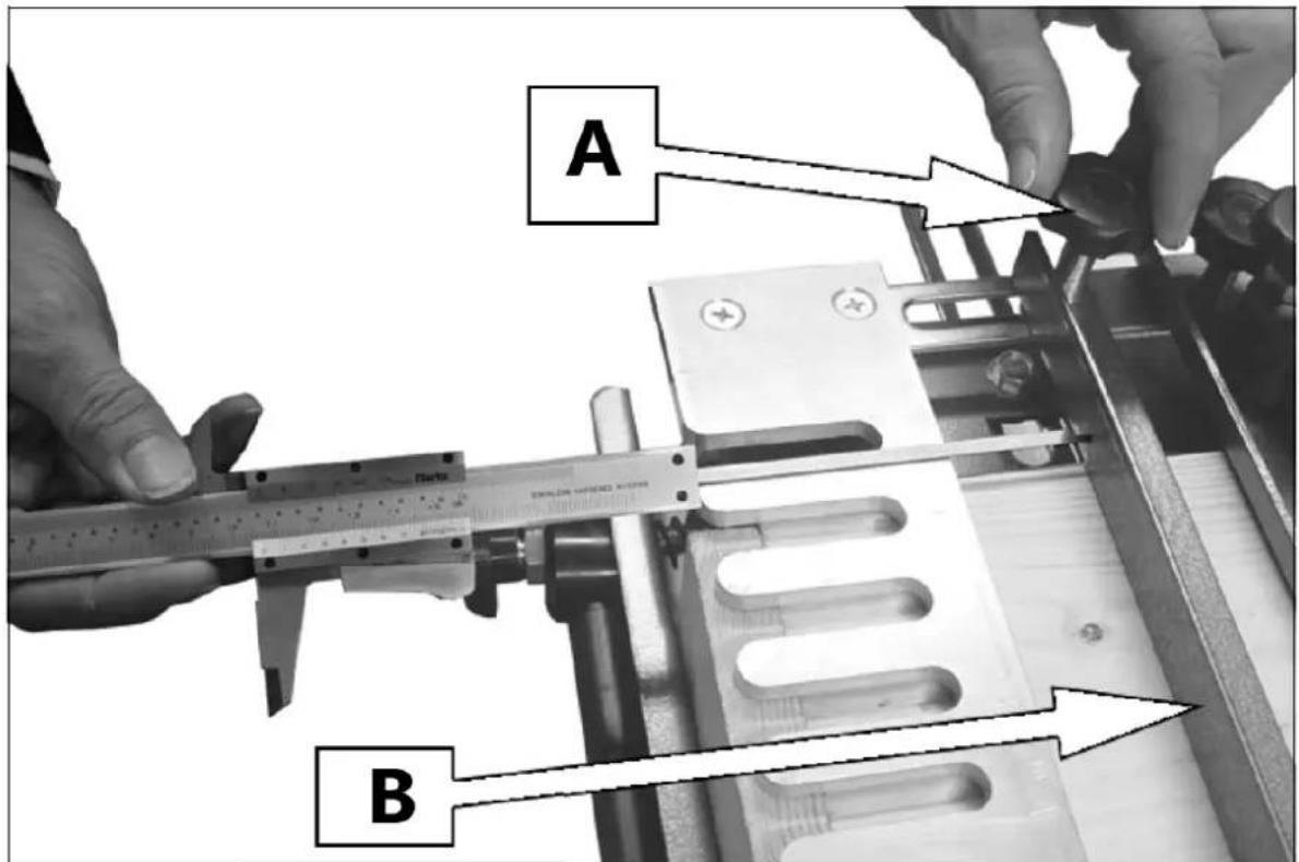
A – Backstop adjustment screw B – Backstop
3.3. Cutting a pattern
Preparation of timber
As with all detailed joinery the components must be sized, cut and squared accurately.
- It is preferable that the width of the timber is in exact steps of 1/2" as this will give a series of fully-formed dovetails.
The joints on the right of the project (1 + 2) are cut on the left hand side of the jig.
The joints on the left of the project (3 + 4) are cut on the right hand side of the jig.
- It is a good idea to identify the drawer pieces as shown, so that they are positioned correctly in the jig.
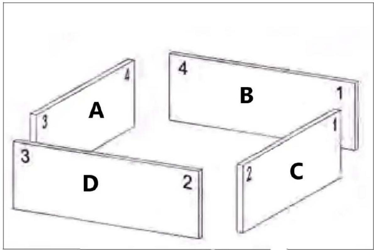
A - Inside-left
B - Inside-back
C - Outside-right
D - Outside-front
The front and back pieces are mounted in the top of the jig with the inside edges facing upwards and the top butting against the horizontal stop.
The left and right pieces are mounted vertically in the front of the jig with the inside edges facing you and the top butting against the vertical stop.
Setting the router cutter depth
1) Fit the bearing guided router bit securely into the router collet.
2) Adjust the cutter depth, until the bottom of the router bit protrudes 10-11 mm below the template fingers.
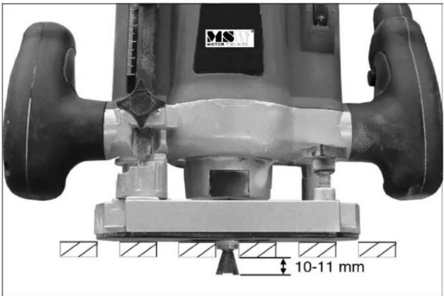
- You may need to fit a packing piece between the template and the timber to ensure good contact between the bearing and the slots in the template.
- The cutting depth is critical to the final fit of the joint, with as little as 0.5mm change in depth making all the difference.
Cutting the joint
You should carry out the initial cuts on two trial pieces of timber of the same width and thickness as the final components. This will allow you to alter various settings in order to get the joint to fit perfectly.
1) Position the router on the template with the cutter clear of the timber and switch on your router.
2) Make the initial cut from the right, across the work, almost touching the end of each finger.
- Avoid heavy-handed contact with the template, allow the router to do the work.
3) Make the remainder of the cuts by following the template in and out of the finger guides working from left to right.
4) When completed, switch the router off before lifting it from the jig.

Caution: do not lift the router from the jig with the router still running.
5) Remove the pieces from the jig, make a trial fit and then, if necessary fine tune the joint by making the following adjustments:
FINE TUNING THE JOINT
| Problem Solution | Problem Solution |
| Pins are too loose | Increase the cutter depth by 0.5 mm. |
| Pins are too tight | Decrease the cutter depth by 0.5 mm. |
| Pins stand out of the connection | Move the back stop further backwards. |
| Pins sit too deep in the connection | Move the back stop further forward. |
| Pieces do not line up | Adjust the horizontal/vertical stops |
6) Having made the necessary adjustments we recommend that you make a second trial cut.
7) Once the correct settings have been made then production runs of joints can be undertaken.
- The settings will need to be checked periodically to maintain accuracy.
Recommended router
- 1200W, 230V motor
- Height Adjustable
• Max plunge depth 50mm - No load speed 13700-30000 RPM
- Collet sizes 6.35mm and 8mm
- Parallel Fence
3.4. Cleaning and maintenance
a) Use only non-corrosive cleaners to clean the surface.
b) After cleaning the device, all parts should be dried completely before using it again.
c) Store the unit in a dry, cool place, free from moisture and direct exposure to sunlight.
d) The device must be regularly inspected to check its technical efficiency and spot any damage.
e) Use a soft cloth for cleaning.
DISPOSING OF USED DEVICES:
Do not dispose of this device in municipal waste systems. Hand it over to an electric and electrical device recycling and collection point. Check the symbol on the product, instruction manual and packaging. The plastics used to construct the device can be recycled in accordance with their markings. By choosing to recycle you are making a significant contribution to the protection of our environment.
Contact local authorities for information on your local recycling facility.

natural_image
Close-up of a mechanical component with a white arrow pointing to a specific feature on a metallic surface (no text or symbols visible)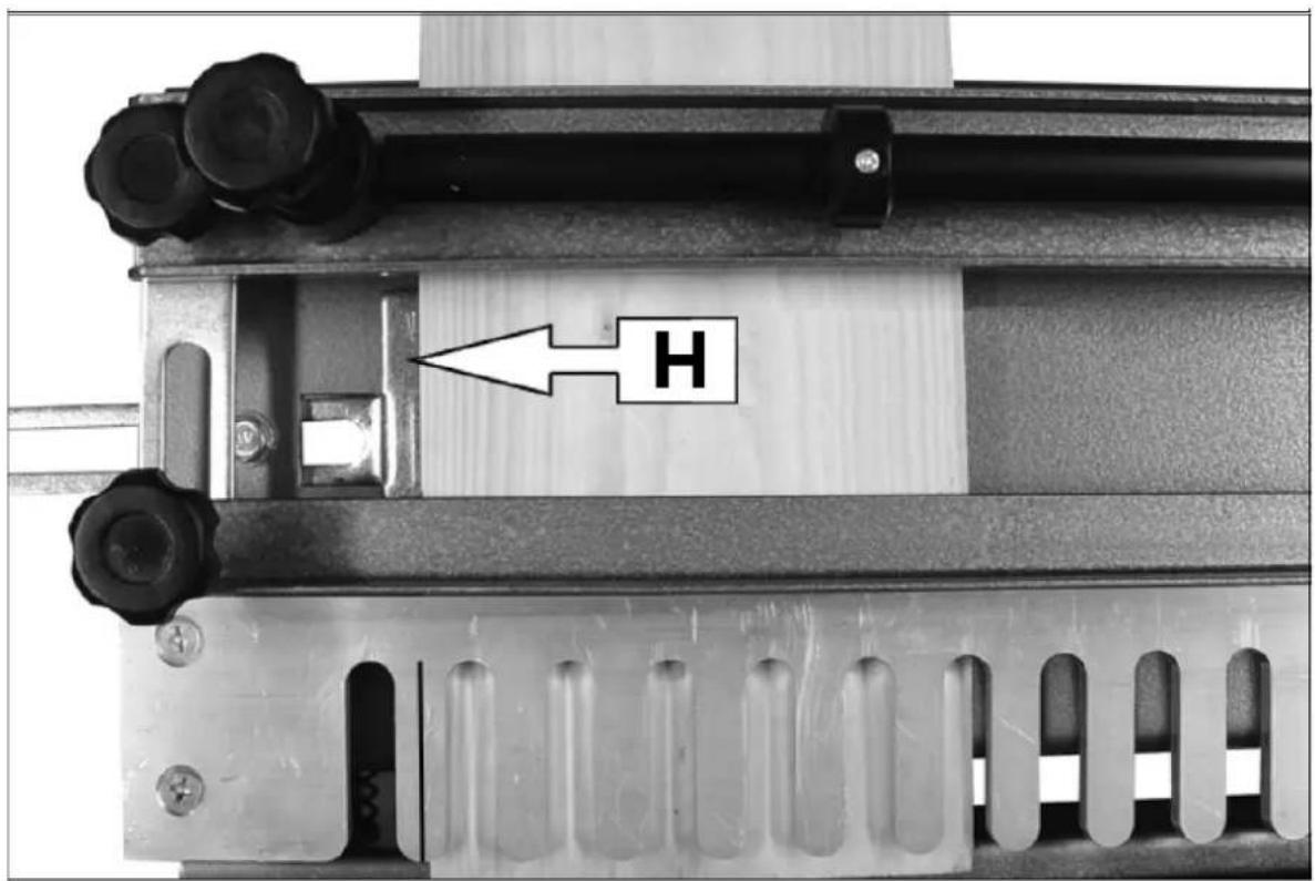
natural_image
Exterior view of a wooden beam joint (no text or symbols visible)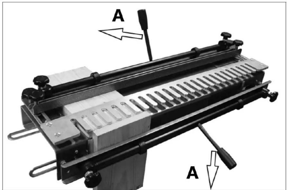
A - Blokada
natural_image
Close-up of a mechanical component with a white arrow pointing to a specific feature on a metallic surface (no text or symbols visible)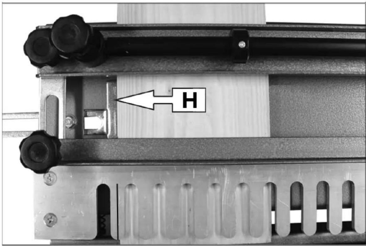
natural_image
Exterior view of a wooden beam joint (no text or symbols visible)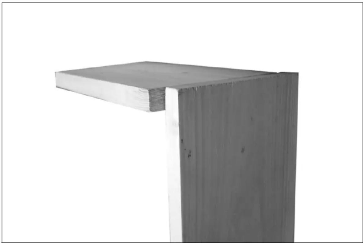
natural_image
Exterior view of a wooden beam joint (no text or symbols visible)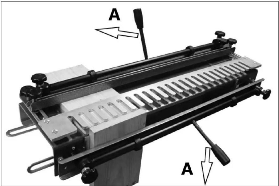
A - zámek
natural_image
Close-up of a mechanical component with a white arrow pointing to a specific feature on a metallic surface (no text or symbols visible)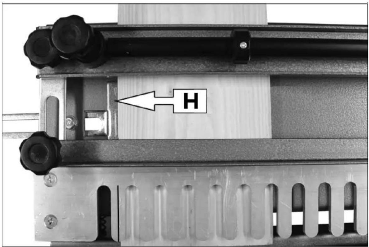
natural_image
Exterior view of a wooden beam joint (no text or symbols visible)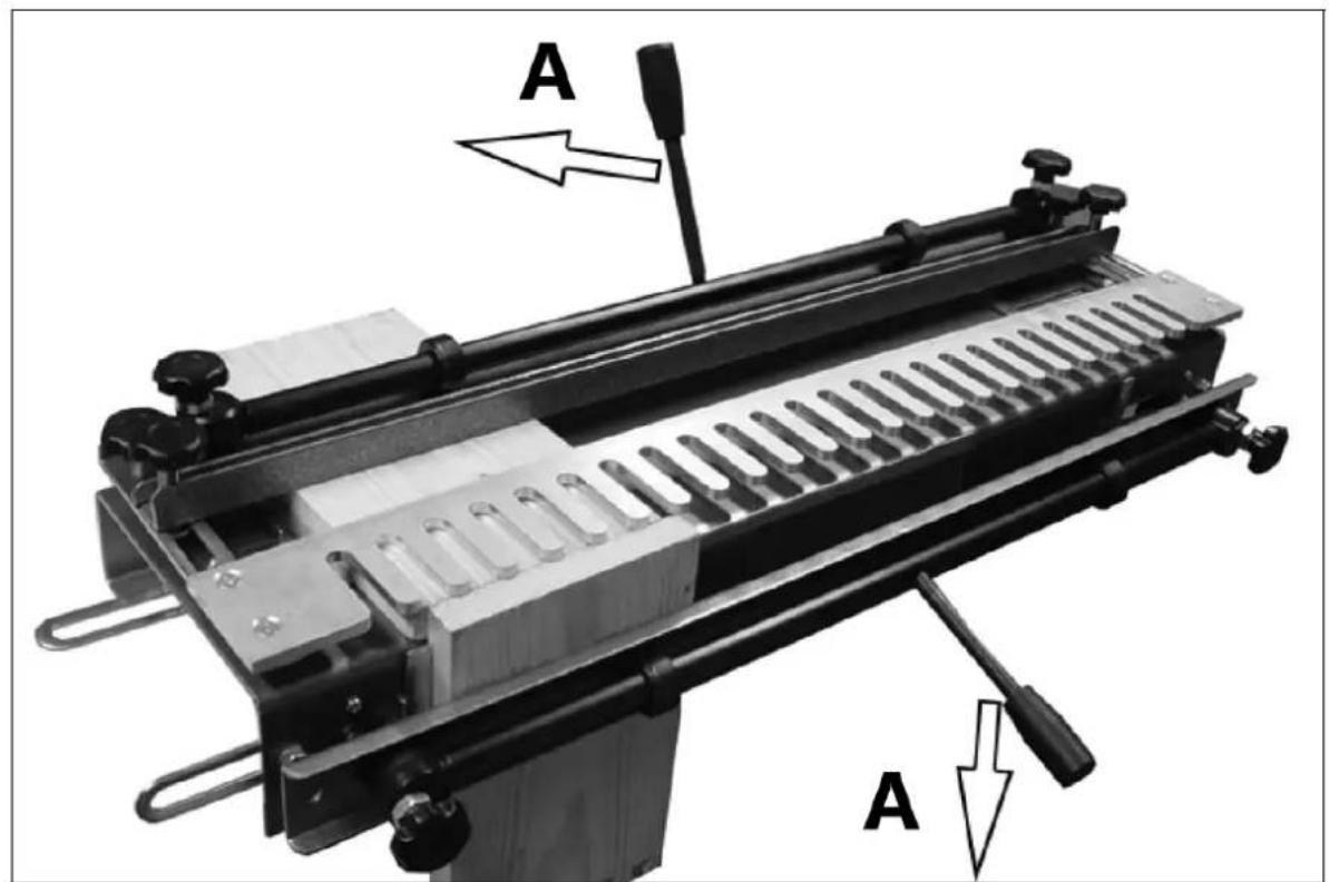
A - verrouillage
natural_image
Close-up of a mechanical component with a white arrow pointing to a specific feature on a metal sheet (no text or symbols visible)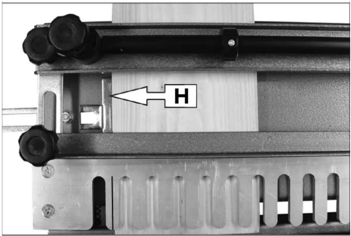
natural_image
Exterior view of a wooden beam joint (no text or symbols visible)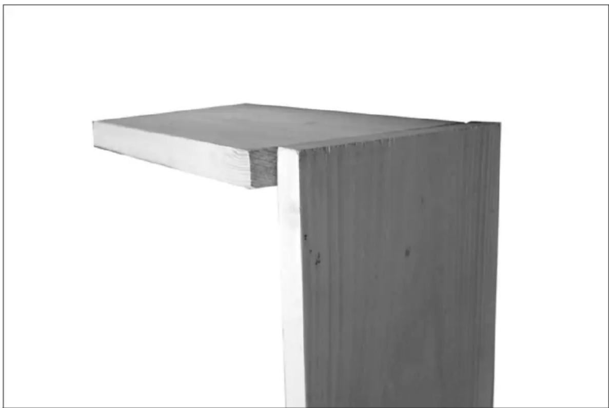
natural_image
Exterior view of a wooden beam joint (no text or symbols visible)A - serratura
natural_image
Close-up of a mechanical component with a white arrow pointing to a specific feature on a textured surface (no text or symbols visible)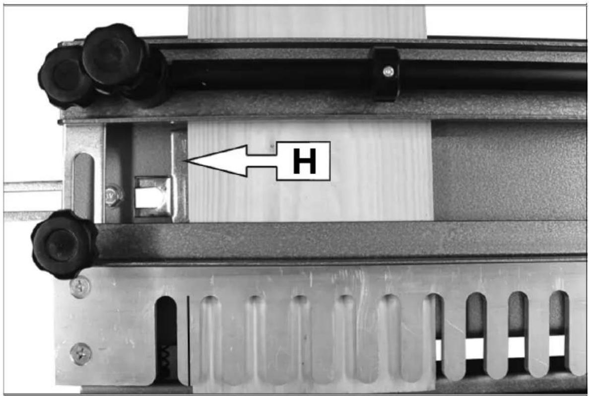
H – Tope horizontal
V - Parada vertical
natural_image
Exterior view of a wooden beam joint (no text or symbols visible)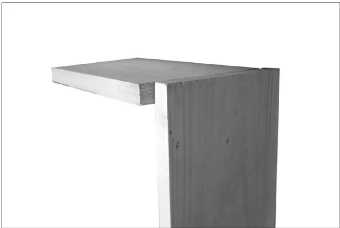
natural_image
Exterior view of a wooden beam joint (no text or symbols visible)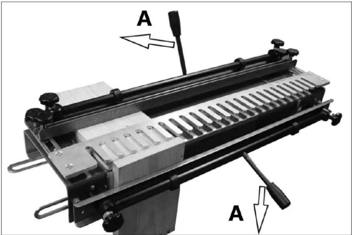
A - cerrar
natural_image
Close-up of a mechanical component with a white arrow pointing to a specific feature on a metallic surface (no text or symbols visible)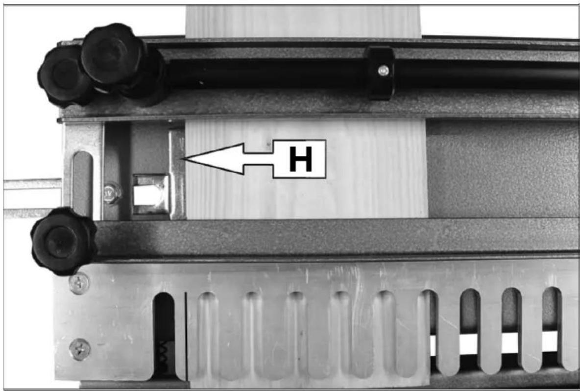
natural_image
Exterior view of a wooden beam joint (no text or symbols visible)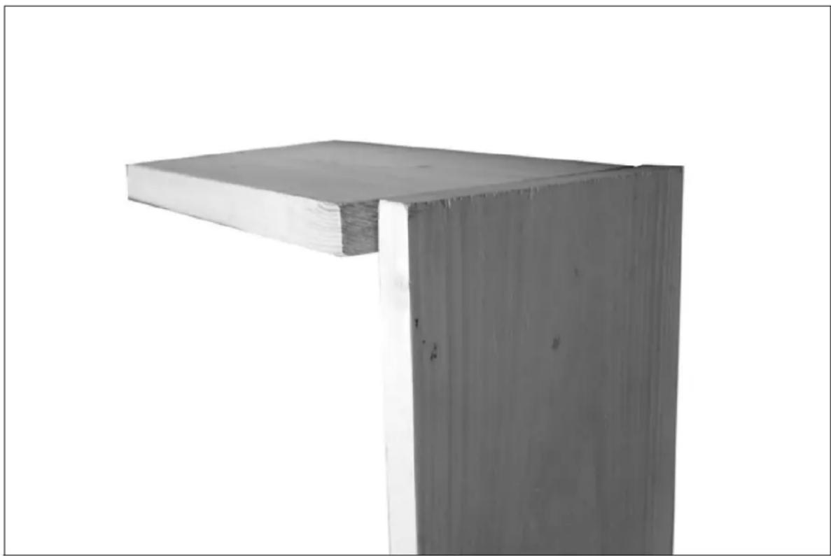
natural_image
Exterior view of a wooden beam joint (no text or symbols visible)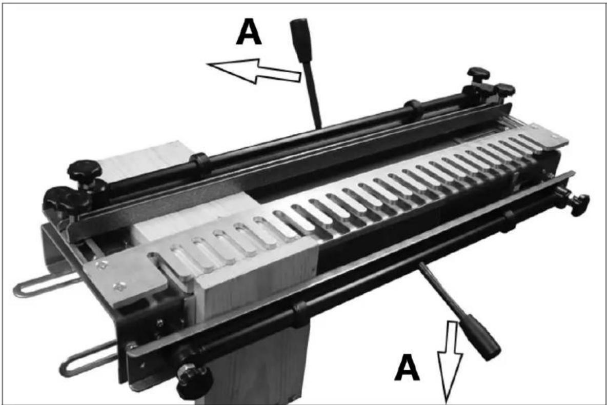
A - lock
natural_image
Close-up of a mechanical component with a white arrow pointing to a specific feature on a metallic surface (no text or symbols visible)DA
H - Vandret stop
V - Lodret stop
natural_image
Close-up of a wooden beam joint or bracket (no text or symbols visible)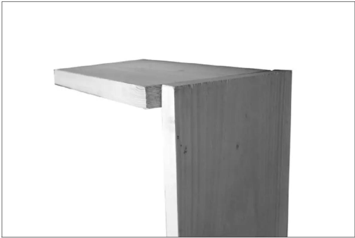
natural_image
Exterior view of a wooden beam joint (no text or symbols visible)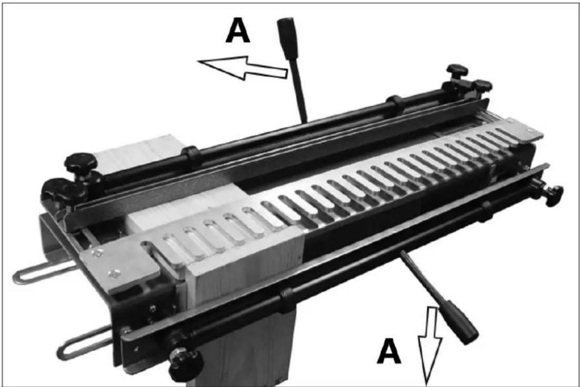
A - lås
natural_image
Close-up of a mechanical component with a white arrow pointing to a slot on a metal sheet (no text or symbols visible)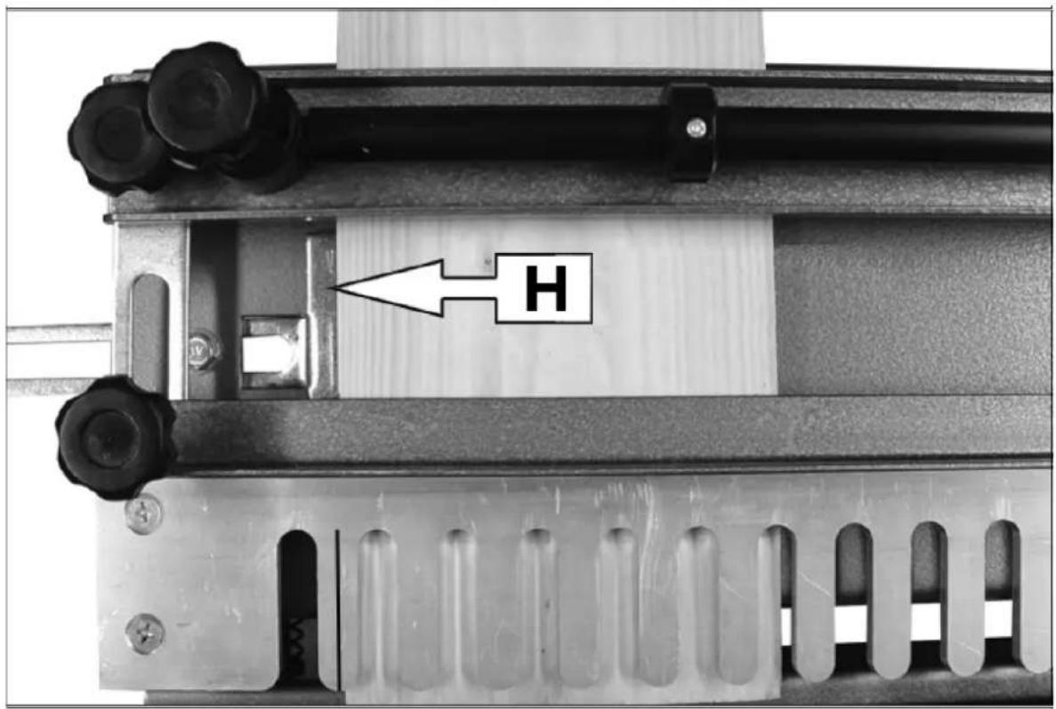
natural_image
Exterior view of a wooden beam joint (no text or symbols visible)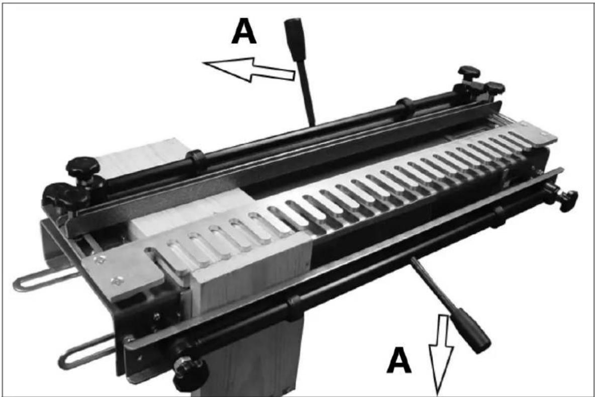
A - Lukko
1 - Vergrendelingsklemhandgreep
2 - Excentrische camera
3 - Excentrische as
4 - Klem
5 - Klemstelschroef
6 - Sjabloonbevestigingsschroef
7 - Achterstop-borgschroef
8 - Horizontale stop
9 - Verticale stop
natural_image
Close-up of a mechanical component with a white arrow pointing to a specific feature on a metallic surface (no text or symbols visible)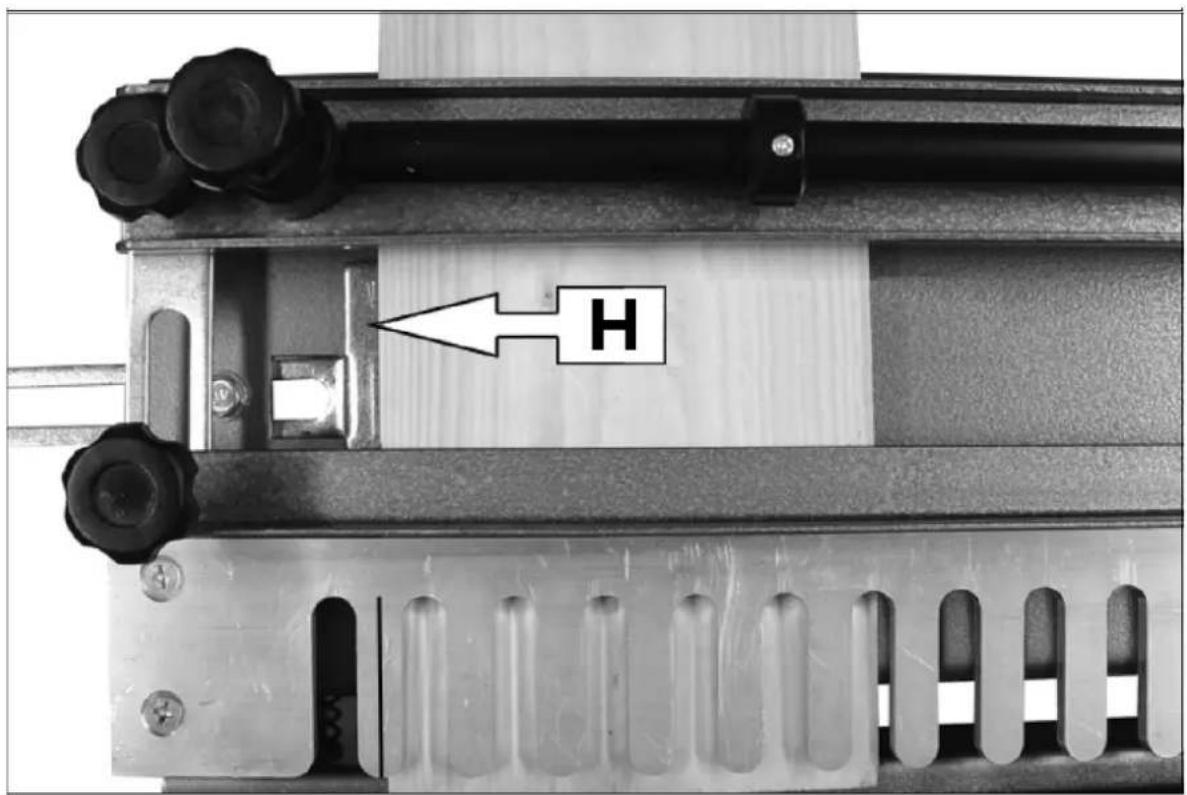
natural_image
Exterior view of a wooden beam joint (no text or symbols visible)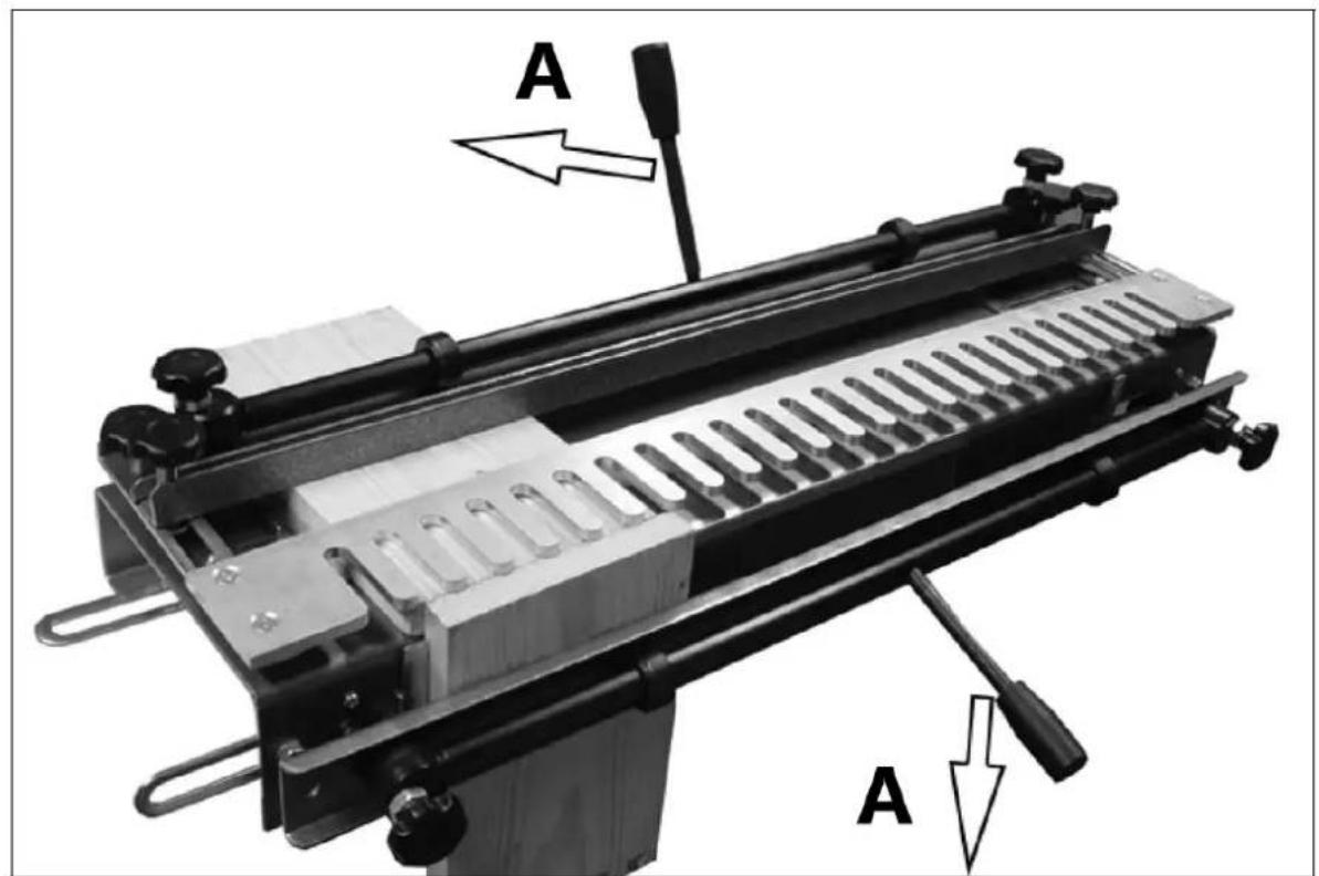
A - slot
1 - Låseklemmehändtak
2 - Eksentrisk kamera
3 - Eksentrisk skaft
4 - Klemme
5 - Klemmejusteringsskrue
6 - Mal sikringsskrue
7 - Tilbakeslagsläseskrue
8 - Horizontal stopp
9 - Vertikal stopp
10 - Bakstopp
11 - Mal
A - Monteringsbrett
B – Sikre deg her
Stille inn endestoppere
1) Bruk en firkant til å tegne en blyantlinje halvveis over malens første finger.
natural_image
Close-up of a mechanical component with a white arrow pointing to a specific feature on a metallic surface (no text or symbols visible)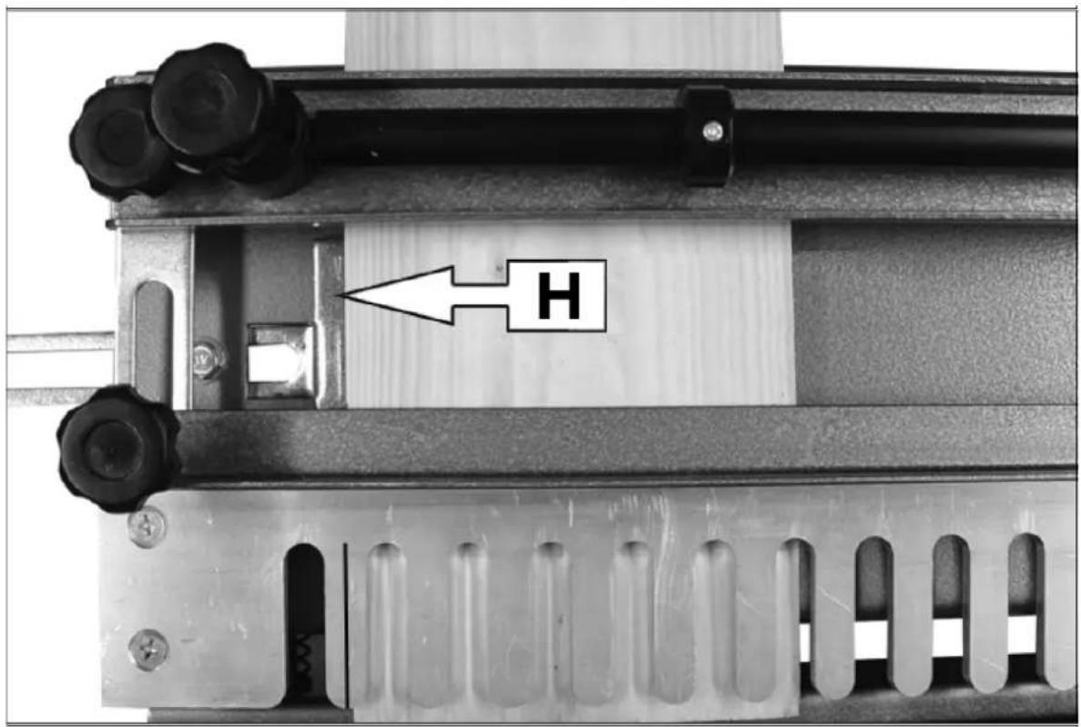
H – Horizontal stopp
V - Vertikal stopp
natural_image
Exterior view of a wooden beam joint (no text or symbols visible)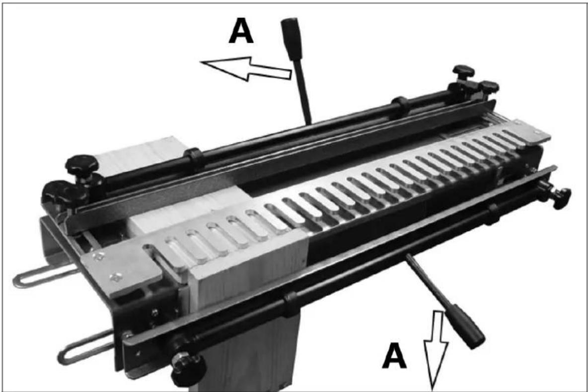
A - läse
Stille inn fresedybden
natural_image
Close-up of a mechanical component with a white arrow pointing to a specific feature on a metallic surface (no text or symbols visible)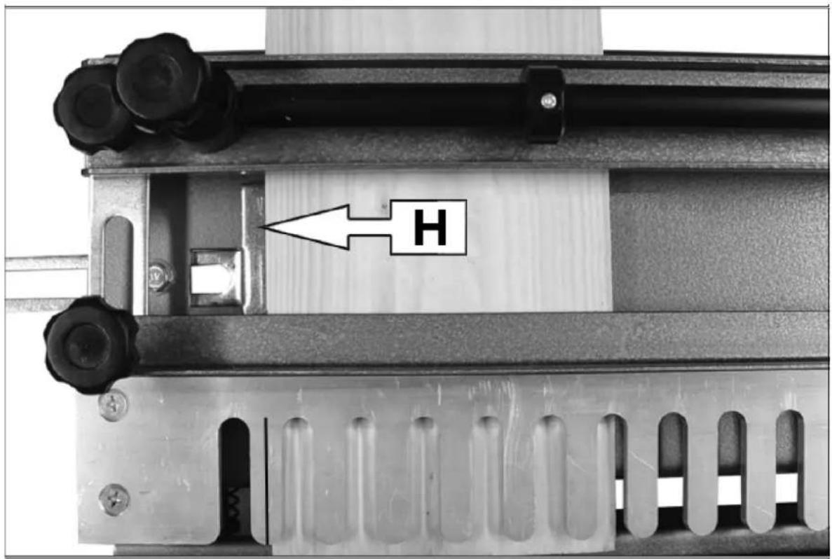
H – Horisontellt stopp
V – Vertikalt stopp
natural_image
Exterior view of a wooden beam joint (no text or symbols visible)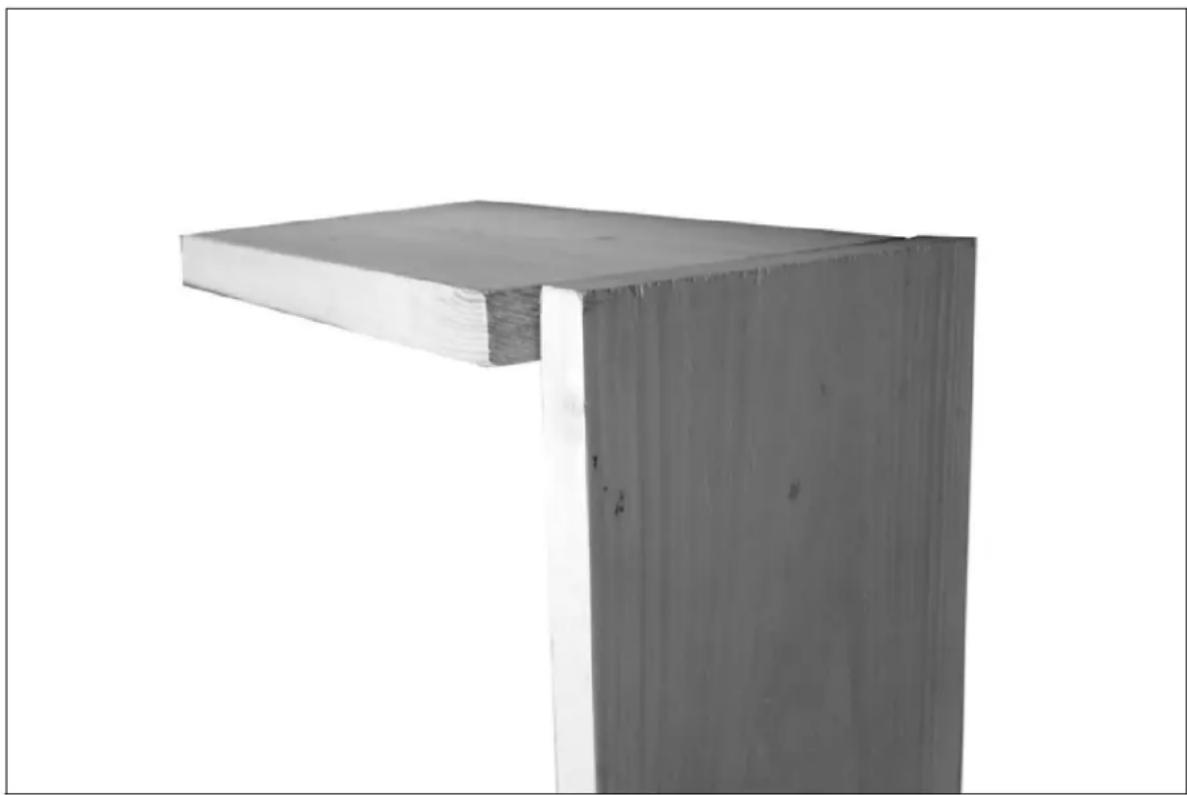
natural_image
Exterior view of a wooden beam joint (no text or symbols visible)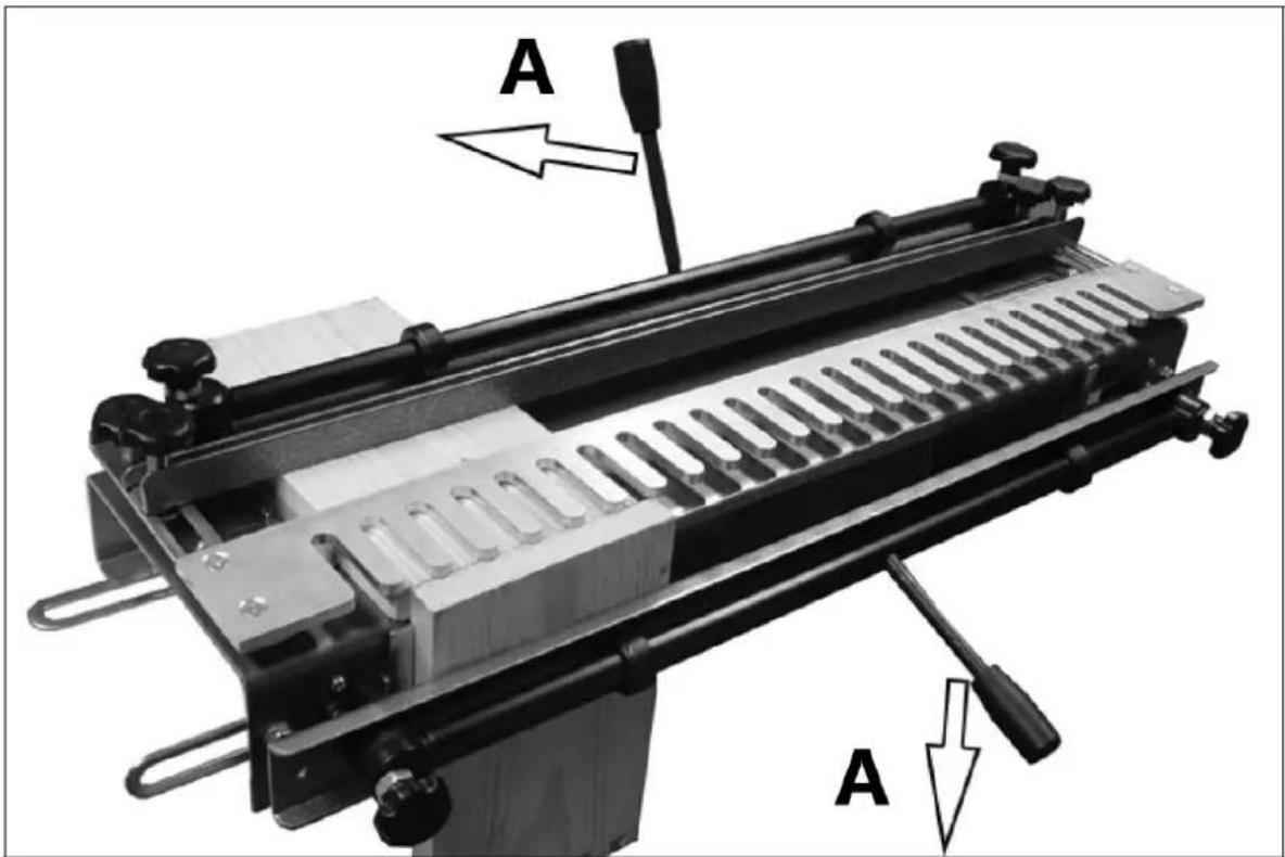
A - läsa
natural_image
Exterior view of a wooden beam joint (no text or symbols visible)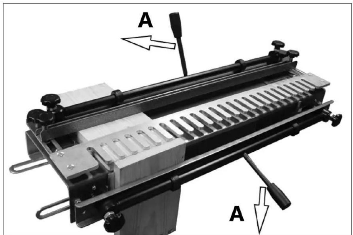
A - trancar
natural_image
Close-up of a mechanical component with a white arrow pointing to a specific feature, no visible text or symbols.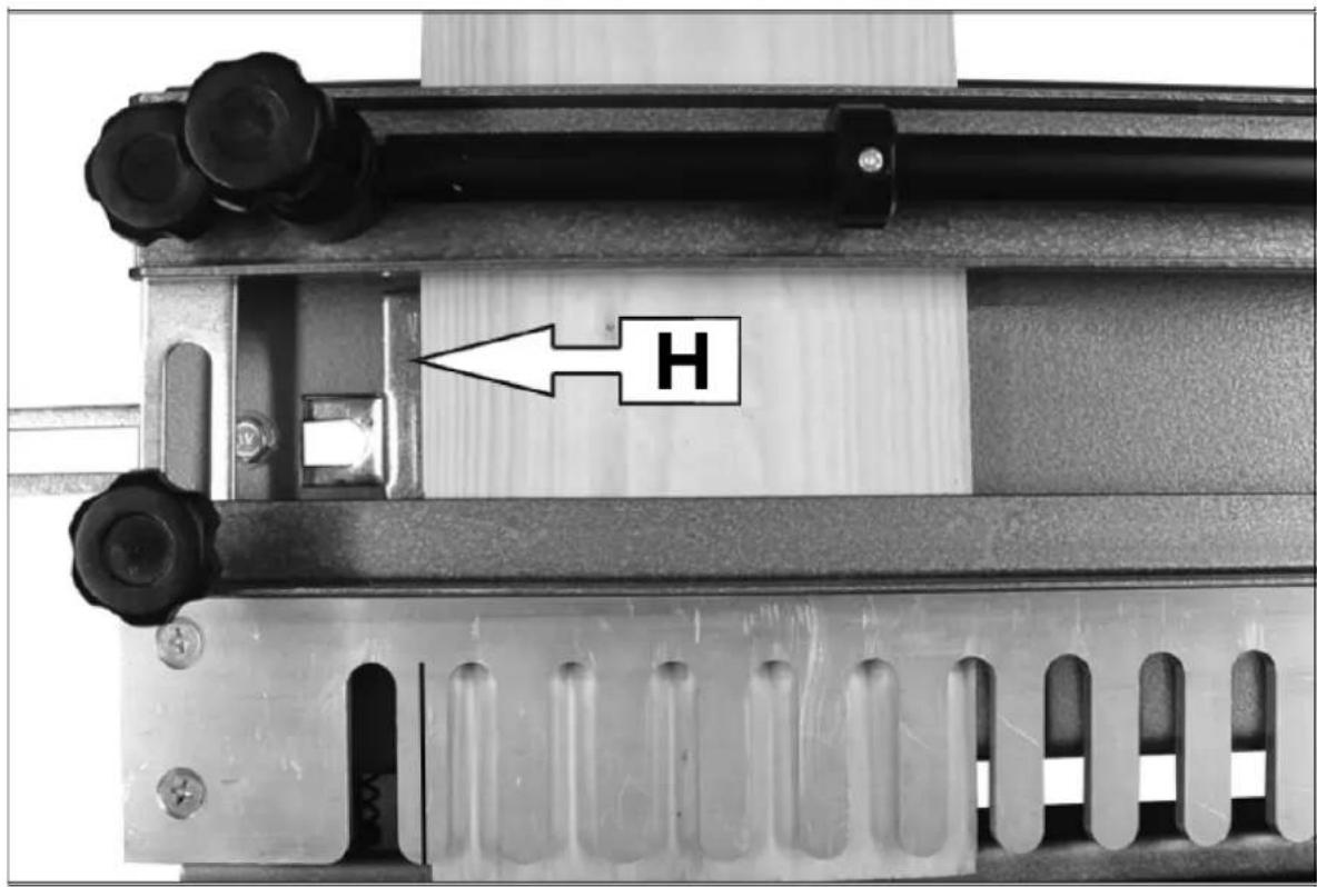
natural_image
Close-up of a wooden beam joint or bracket with visible grain and texture (no text or symbols)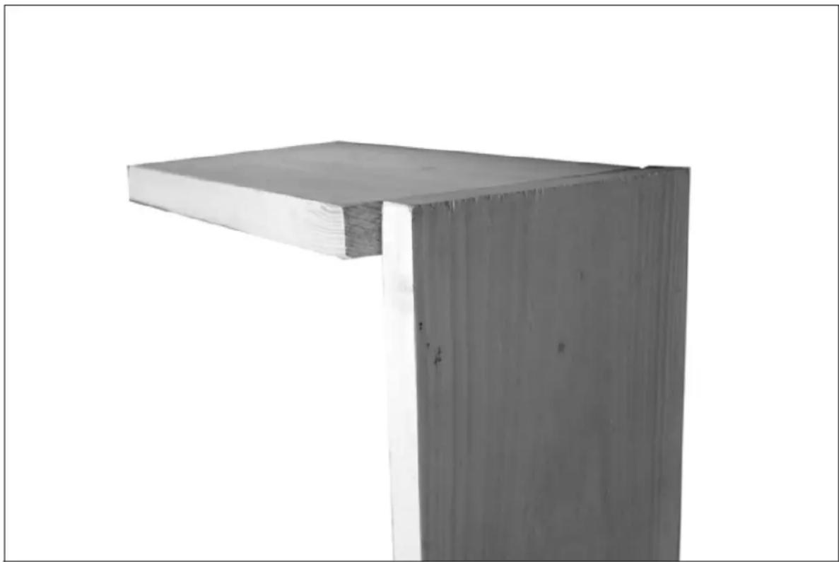
natural_image
Exterior view of a wooden beam joint (no text or symbols visible)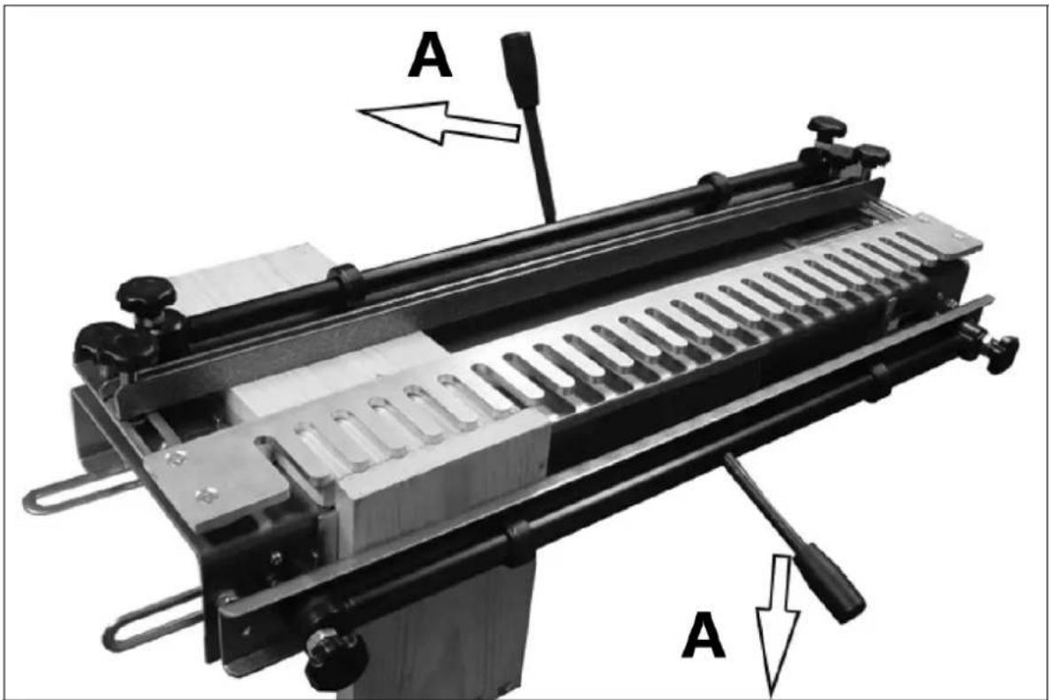
A - zámok
For the disposal of the device please consider and act according to the national and local rules and regulations.
CONTACT
expondo Polska sp. z o.o. sp. k.
- General description
- DO NOT USE THE DEVICE UNLESS YOU HAVE THOROUGHLY READ AND UNDERSTOOD THIS USER MANUAL.
- Legend
- Usage safety
- Safety in the workplace
- Personal safety
- Safe device use
- Use guidelines
- Device description
- Preparation for use
- Assembling the jig
- Mounting the jig
- Setting the end stops
- Placing the timber into the jig
- Setting the template position
- Setting the backstop position
- Example
- Cutting a pattern
- Preparation of timber
- Setting the router cutter depth
- Cutting the joint
- Recommended router
- Cleaning and maintenance
- DISPOSING OF USED DEVICES:
- Stille inn endestoppere
- Stille inn fresedybden
- CONTACT
Brand : MSW
Model : JJS-E1P
Category : Sander