S-LS-15 Basic - Welding machine Stamos - Free user manual and instructions
Find the device manual for free S-LS-15 Basic Stamos in PDF.

User questions about S-LS-15 Basic Stamos
0 question about this device. Answer the ones you know or ask your own.
Ask a new question about this device
Download the instructions for your Welding machine in PDF format for free! Find your manual S-LS-15 Basic - Stamos and take your electronic device back in hand. On this page are published all the documents necessary for the use of your device. S-LS-15 Basic by Stamos.
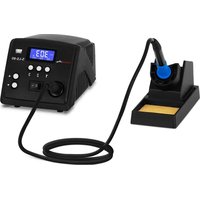
USER MANUAL S-LS-15 Basic Stamos
TECHNISCHES DATENBLATT
text_image
Technical diagram of a soldering iron with numbered parts for identificationGeneral safety information for the use of electrical devices:
To avoid injury from fire or electric shock, please ensure compliance with safety instructions when using this device. Please read the instruction carefully and make sure that you have understood them well. Keep the manual near the equipment to be able to read it at any time. Always use current sources connected to the ground and providing the necessary voltage (indicated on the label on the device). If you have any doubt, let an electrician check that your outlet is properly grounded. Never use a damaged power cable. Do not open the unit in damp or wet environment, or if your hands or body are damp or wet. Protect the unit from solar radiation. Use the device in a protected location to avoid damaging the equipment or endangering others. Make sure the device is able to cool and avoid placing it too close to other devices that produce heat. Before cleaning, disconnect it. Use a soft damp cloth for cleaning. Avoid using detergent and make sure that no liquid enters the unit. No internal element of this device needs to be maintained by the user. An opening of the device without our approval leads to a loss of warranty.
General safety information for the use of the device:
- The user manual should be kept close to the device and should always be accessible for the users. Instruct your employees how to use the device properly.
- Make sure the hot air can circulate well and place the device more than 10 cm away from walls and other electrical devices. Properly aerate the working area.
- Do not place the device close to combustible materials.
- When first using the device the heating element may produce a light smoke. This is absolutely normal. Simply ensure that the smoke can evaporate and that a good aeration is provided.
- Some parts of the device can get extremely hot. To avoid any injuries, be careful whenever you come into contact with the device.
- Clean the device regularly to avoid permanent accumulation of dirt.
TECHNICAL DETAILS
| Model 6131 S-LS-15 Basic | |
| Voltage (V) 230 ~ 50Hz | |
| Rated current (A) 10 | |
| Power (W) 1415 | |
| Work temperature (°C) | 0 / +40 |
| Storage temperature (°C) | -20 / -80 |
| INFRARED LAMP | |
| Voltage (V) 230 ~ 50Hz | |
| Power (W) 150 | |
| Irradiation effective area (mm) 35 x 35 | |
| Temperature range (°C) | 100 - 350 |
| SOLDERING IRON | |
| Temperature range (°C) | 200 - 480 |
| Output power (W) 75 | |
| Temperature stability (°C) | ±1 |
| Tip to ground resistance < 2 Ω | |
| Tip to ground voltage < 2 mV | |
| SMD REWORK | |
| Temperature range (°C) | 100-480 |
| Output power (W) 700 | |
| Temperature stability (°C) | ± 1 |
| Airflow (L/min) 120 | |
| PREHEATER | |
| Output power (W) 540 | |
| Temperature range (°C) | 50 - 200 |
| Plate dimensions (mm) | 120 × 120 |
USAGE PURPOSE
The device is designed for:
-
Different kinds of soldering, de-soldering of the electronic components such as: SOIC, CHIP, QFP, PLCC, SMD, etc. especially for BGA modules, motherboards in electronic devices.
-
Shrinking, paint drying, adhesive removal, thawing, warming, plastic welding.
Any damage resulting from a non-conform use of the device is to be paid by the user!
- infrared lamp switch on / off
- infrared lamp temperature display
- external sensor temperature display
- infrared lamp temperature setting buttons
- preheater switch on / off
- preheater temperature display
- preheater temperature set buttons
- soldering iron switch on / off
- soldering iron temperature display
- soldering iron temperature set buttons
- SMD rework gun switch on /off
- SMD rework temperature display
- SMD rework temperature set buttons
- airflow volume adjustment knob
Hinterpaneel:
| POWER | INPUT |
| OR | 1 |
| CHP | 2 |
| 3 | |
| 4 | |
| 5 | |
| 6 | |
| 7 | |
| 8 | |
| 9 | |
| 10 | |
| 11 | |
| 12 | |
| 13 | |
| 14 | |
| 15 | |
| 16 | |
| 17 | |
| 18 | |
| 19 | |
| 20 | |
| 21 | |
| 22 | |
| 23 | |
| 24 | |
| 25 | |
| 26 | |
| 27 | |
| 28 | |
| 29 | |
| 30 | |
| 31 | |
| 32 | |
| 33 | |
| 34 | |
| 35 | |
| 36 | |
| 37 | |
| 38 | |
| 39 | |
| 40 | |
| 41 | |
| 42 | |
| 43 | |
| 44 | |
| 45 | |
| 46 | |
| 47 | |
| 48 | |
| 49 | |
| 50 | |
| 51 | |
| 52 | |
| 53 | |
| 54 | |
| 55 | |
| 56 | |
| 57 | |
| 58 | |
| 59 | |
| 60 | |
| 61 | |
| 62 | |
| 63 | |
| 64 | |
| 65 | |
| 66 | |
| 67 | |
| 68 | |
| 69 | |
| 70 | |
| 71 | |
| 72 | |
| 73 | |
| 74 | |
| 75 | |
| 76 | |
| 77 | |
| 78 | |
| 79 | |
| 80 | |
| 81 | |
| 82 | |
| 83 | |
| 84 | |
| 85 | |
| 86 | |
| 87 | |
| 88 | |
| 89 | |
| 90 | |
| 91 | |
| 92 | |
| 93 | |
| 94 | |
| 95 | |
| 96 | |
| 97 | |
| 98 | |
| 99 | |
| 100 |
- main on/off switch
- power socket
- soldering iron connection socket
- SMD rework connection socket
- IR lamp connection socket
- temperature units switch (C / F)
- light switch
- light connection socket
EN
EN
BEFORE FIRST USE
Upon receipt of the goods, check the packaging for integrity and open it. If the packaging is damaged, please contact your transport company and distributor within 3 days, and document the damages as detailed as possible. Do not turn the package upside down! When transporting the package, please ensure that it is kept horizontal and stable. Please keep all packaging materials (cardboard, plastic tapes and styrofoam), so that in case of a problem, the device can be sent back to the service centre in accurate condition.
Disposing of packaging
The various items used for packaging (cardboard, plastic straps, polyurethane foam) should be conserved, so that the device can be sent back to the service centre in the best condition in case of any problems!
INSTALLING THE APPLIANCE
Appliance location
The work surface where the device will be located must be suitable for the size of the appliance, please refer to the measurements. The work surface must be levelled, dry, heat-resistant and at a fitting height from the ground to enable a proper use of the device.
The power cord connected to the appliance must be properly grounded and correspond to the technical details.
INFRARED LAMP
- Device must be placed on stable work table.
- Connect the device to the power source.
- Turn on the device with the main switch placed at the back of the device, turn on the infrared lamp with switch (1).
- Temperature setting: using buttons (4) set the desired temperature. Displays (2) and (3) will show the infrared lamp temperature and external sensor temperature.
- After work, turn off the infrared lamp by switch (1).
- If the device is not being used for a long time, it should be completely disconnected from the power source.
SMD REWORK STATION
- Device must be placed on stable work table, SMD rework gun must be placed into the holder.
- Fix the appropriate nozzle and connect the device to the power source.
- Turn on the device with the main switch placed at the back of the device, turn on the SMD rework gun with switch (11), gun will start to heat.
- Temperature setting: using buttons (13) set the desired temperature. Temperature will be shown on the display (12).
- Airflow volume adjustment: set the desired airflow volume using knob (14).
- After work, the SMD rework gun should be placed into the holder. Turn off the SMD rework by switch (11).
- If the device is not being used for a long time, it should be completely disconnected from the power source.
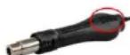
- NOTE: It is forbidden to cover the air intake holes on the handle of a SMD rework gun during work. This may cause serious damages of the fan and the heater!
SOLDERING IRON OPERATION
- Device must be placed on stable work table, soldering iron must be placed into the holder.
- Fix the appropriate soldering tip and connect the device to the power source.
- Turn on the device with the main switch placed at the back of the device, turn on the soldering iron with switch (8), it will start to heat.
- Temperature setting: using buttons (10) set the desired temperature. Temperature will be shown on the display (9).
- After work, the soldering iron should be placed into the holder. Turn off the soldering station by switch (8).
- If the device is not used for a long time, it should be completely disconnected from the power source.
PREHEATER OPERATION
- Device must be placed on stable work table.
- Connect the device to the power source.
- Turn on the device with the main switch placed at the back of the device, turn on the preheater plate with switch (5), it will start to heat.
- Temperature setting: using buttons (7) set the desired temperature. Temperature will be shown on the display (6).
- After work, turn off the preheating plate by switch (5).
- If the device is not used for a long time, it should be completely disconnected from the power source.
CHANGING THE TEMPERATURE DISPLAY UNITS
Switch (6) is designed for changing the temperature units between Celsius and Fahrenheit ( ^0 C – Celsius, ^0 F – Fahrenheit)
TEMPERATURE COMPENSATION
Compensation temperature setting procedure:
- For the soldering iron / SMD rework / preheating plate: turn on the devices, and then press and hold both temperature setting buttons for about 3 seconds. Display will show "00". Using appropriate buttons (7) / (10) / (13) set the desired temperature compensation for each of the devices (-50 °C \~ +50 °C.). After setting the temperature compensation, do not press any button for about 3 seconds - device will save changes and will go into work mode.
- Setting the power compensation of the infrared lamp: turn off the infrared lamp, press and hold both temperature setting buttons, then turn on the infrared lamp and wait until display will show "20". Release the buttons and set the compensation value.
- Setting the temperature compensation of the external sensor: turn on the infrared lamp, then press and hold both temperature setting buttons for about 3 seconds. Display will show "00". Release the buttons and set the compensation value (-50 °C \~ +50 °C.). After setting the temperature compensation, do not press any button for about 3 seconds – device will save changes and will go into work mode.
EN EN
GENERAL REMARKS
- If the display is showing the „---, it means that the output temperature is lower than 100 □C, SMD rework station is in stand-by mode, SMD rework gun is placed in the holder.
- If the display is showing "S-E" It means that soldering iron is disconnected, and HOT AIR gun is having problems with the heat sensor.
- When the device is being turned on, both soldering iron and HOT AIR gun should be placed in their holders.
- The outlet of the SMD rework gun should be clean and free from any obstacles.
- When using small nozzles, it should be remembered that the air flow should be suitable to the diameter of the fixed nozzle. In order to avoid any SMD rework gun damages, too high air flow along with the high temperature mustn't be used for a long period of time.
- Depending on user's needs, different air flow settings may cause slight variations in temperature values. The minimum distance between the outlet of the HOT AIR gun and the subject is 2 mm.
- Good ventilation of the room in which the appliance is used must be provided. In addition, the device should be placed in a location with good air circulation to dissipate heat.
SAFETY ISSUES REMARKS
- Nozzles should be installed without the use of excessive force, also do not use the pliers or tweezers. Do not tighten the mounting screws of the nozzle too much.
- Tips and nozzles can be changed when the SMD rework gun and the soldering iron are completely cold.
- It is forbidden to use the device near flammable or combustible elements and objects or in similar places. Tips and nozzles as well as the air coming out of the HOT AIR gun have very high temperatures, it is forbidden to touch these elements as well as it is forbidden to direct the hot air directly to face or body. This can cause serious burns.
- After long time of use, the outlet of the SMD rework gun may be covered with some dust. The outlet should be cleaned on a regular basis in order to ensure undisturbed air flow.
- Too high temperature of the soldering iron may be the cause of reduction of the functionality of the soldering tips.
- Soldering iron tip must be cleaned regularly using sponge and plate on a layer of tin to prevent tips oxidation.
REPLACEMENT OF HOT AIR REWORK HEATING ELEMENT
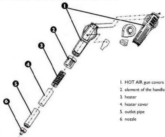
text_image
1. HOT AIR gun covers 2. element of the handle 3. heater 4. heater cover 5. outlet pipe 6. nozzle- Before heater replacement, make sure that the SMD rework gun is completely cold.
- Remove the screws in the gun covers.
- Unscrew the element of the handle (2) and take off the gun covers.
- Gently remove the fan and remove the wire board screws.
- Disconnect the heater from the wire board (pay attention to the wires connection order).
- Remove the heater from the housing, pay attention to the steel grounding wire.
- New heater should be wrapped with new mica paper and then it should be placed inside the housing.
- Connect the wires to the board in accordance with their original connection method.
- Fix the gun in reverse order.
REPLACEMENT OF THE SOLDERING IRON TIP AND SOLDERING IRON HEATING CORE ELEMENT
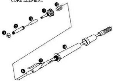
text_image
CORE ELEMENT ① ② ③ ④ ⑤ ⑥ ⑦- nut for mounting the soldering iron tip housing
- soldering iron tip housing
- soldering iron tip
- plastic nut for mounting the heater and the board wires
- spring
6 heater - wires board
- handle
EN
BEFORE HEATER / SOLDERING IRON TIP REPLACEMENT MAKE SURE THAT THE SOLDERING IRON IS COMPLETELY COLD.
- SOLDERING IRON TIP REPLACEMENT: remove the nut for mounting the soldering iron tip housing and take off the housing. Replace the tip with the new one, place the housing and fix all with the plastic nut.
- HEATER REPLACEMENT; remove the nut for mounting the soldering iron tip housing and take off the housing along with the tip. Remove the nut for fixing the heater (4) and gently remove the heater (6) along with the board with wires (7). Replace the whole remembering the wires connection order.
INFRARED LAMP AND COVER REPLACEMENT
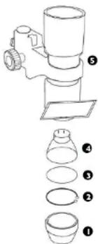
text_image
Diagram showing a mechanical assembly with numbered parts, likely illustrating a step-by-step assembly or manufacturing process.- lamp cover
- ring
- quartz plate
- infrared lamp
-
infrared lamp components
-
Unscrew the lamp cover (1) and replace it.
- Remove the ring (2) paying attention to the quartz plate (3). Remove the quartz plate, disassemble the infrared lamp components (5), remove the lamp and replace it.
- Fix the lamp in reverse order.
REGULAR CLEANING
Generalities
- Never clean the device with a pressurized water-jet, industrial cleaners, and brushes or any other type of cleaning utensil that could damage the surface of the appliance.
- Before cleaning you must disconnect the plug from electricity supply, isolating the appliance from the main power circuit.
REGULAR CONTROL OF THE DEVICE
Control regularly that the device doesn't present any damage. If there is any damage, please stop using the device. Please contact your customer service to solve the problem.
What to do in case of problem?
Please contact your customer service and prepare following information:
- Invoice number and serial number (the latest is to be found on the technical plate on the device).
- If relevant, a picture of the damaged, broken or defective part.
- It will be easier for your customer service clerk to determine the source of the problem if you give a detailed and precise description of the matter. Avoid formulations like "the device doesn't heat", which may mean that it doesn't heat enough or even not at all. These two possibilities have a different causation!
The more detailed your information, the better the customer service will be able to answer your problem rapidly and efficiently!
CAUTION: Never open the device without the authorization of your customer service. This can lead to a loss of warranty!
IPL
PL
PL
ZALECENIA ODNOŚNIE BEZPIECZEŃSTWA
text_image
POWER ON OFF 1 6 ● ● ● 40 225V TA SOLKARBO IRON HOT AIR IN HAY LAMP °C ● ● ● °F LIGHTS SENSORtext_image
Technical diagram of a soldering iron with numbered parts for identificationtext_image
Diagram of a mechanical device with numbered parts, likely illustrating a multi-step assembly or manufacturing process.text_image
POWER ON OFF ① INPUT ② ③ ④ ⑤ °C LIGHTS 6 7 8 F LIGHTS SENSORtext_image
Technical diagram of a soldering iron with numbered parts for identificationtext_image
Diagram of a mechanical device with numbered parts for identificationtext_image
Technical diagram of a soldering iron with numbered parts for identificationtext_image
Diagram showing a mechanical device with numbered parts for assembly or cleaning stepsWe hereby certify that the appliances listed in this manual are Ce compliant.
FR
For the disposal of the device please consider and act according to the national and local rules and regulations.