IPD-4000-4WM-220 - Heating MSW - Free user manual and instructions
Find the device manual for free IPD-4000-4WM-220 MSW in PDF.

| Product type | Infrared paint dryer |
| Brand | MSW |
| Model | IPD-4000-4WM-220 |
| Supply voltage | 230 V~ / 50 Hz |
| Current | Single-phase |
| Rated power | 4000 W (4 x 1000 W) |
| Protection class | I |
| Protection rating (IP) | IP32 |
| Dimensions (L x D x H) | 590 x 1150 x 2500 mm |
| Weight | 44 kg |
| Temperature range | 40–100 °C |
| Operating time | 0–99 min |
| Maximum hardening area | 1200 x 1000 mm |
| Ambient conditions | 5–40 °C, humidity 20–95% |
| Operating modes | Standard (Routine) and Pulse (Pulse) |
| Number of lamps | 4 |
| Recommended lamp-surface distance | 30–60 cm |
| Type of radiation | Short-wave infrared |
| Power supply | Mains 230 V |
| Safety devices | Residual-current circuit breaker, emergency stop |
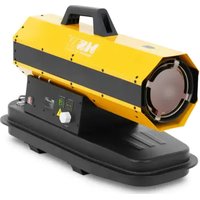
| Intended use | Drying of paint and fillers in car body repair |
| Maintenance | Clean with a soft cloth; do not immerse; replace lamps |
| Repairability | Repair by manufacturer's after-sales service only |
Frequently Asked Questions - IPD-4000-4WM-220 MSW
User questions about IPD-4000-4WM-220 MSW
0 question about this device. Answer the ones you know or ask your own.
Ask a new question about this device
Download the instructions for your Heating in PDF format for free! Find your manual IPD-4000-4WM-220 - MSW and take your electronic device back in hand. On this page are published all the documents necessary for the use of your device. IPD-4000-4WM-220 by MSW.
USER MANUAL IPD-4000-4WM-220 MSW
natural_image
Close-up of a black and silver bicycle steering wheel (no text or symbols visible)natural_image
Close-up of a mechanical device with a circular vent and lever mechanism (no visible text or symbols)natural_image
Simple line drawing of an electrical outlet with two hexagonal connectors (no text or symbols)natural_image
Simple line drawing of a rectangular container with internal compartments and a side panel (no text or symbols)(2)
natural_image
Pure mechanical component diagram without any text, numbers, or symbols(3)
(4)

(5)
CAUTION! This User Manual has been translated for your convenience using machine translation. Reasonable efforts have been made to provide an accurate translation; however, no automated translation is perfect nor is it intended to replace human translators. The official User Manual is the English version. Any discrepancies or differences created in the translation are not binding and have no legal effect for compliance or enforcement purposes. If any questions arise related to the accuracy of the information contained in the User Manual, please refer to the English version of those contents which is the official version.
Technical Data
| Description of the Parameter | Value of the Parameter |
| Product name | INFRARED PAINT DRYER |
| Model | MSW-IPD-4000-4WM-220 |
| Supply voltage [V~] / Frequency [Hz] | 230/50 |
| Electricity | 1-phase |
| Rated power [W]. | 4 x 1000 |
| Safety class | I |
| IP code | IP32 |
| Dimensions [Width x Depth x Height; mm] | 590 x 1150 x 2500 |
| Weight [kg] | 44 |
| Time range [min] | 0-99 |
| Temperature range[°C] | 40–100* |
| * The temperature depends on the setting and distance of the radiator from the surface to be treated. | |
| Maximum curing area [mm] | 1200 x 1000 |
| Application conditions | Ambient temp. 5~+40 °CHumidity 20~95% |
1. General Description
The instruction manual is intended to assist in safe and reliable use. The product is designed and manufactured strictly according to technical specifications using the latest technology and components and maintaining the highest quality standards.
PLEASE CAREFULLY READ AND UNDERSTAND THIS INSTRUCTION MANUAL BEFORE OPERATION,
To ensure long and reliable operation of the unit, make sure to operate and maintain it properly in accordance with the guidelines in this instruction manual. The technical data and specifications contained in this instruction manual are up to date. The manufacturer reserves the right to make changes in order to improve the quality. Taking the technical progress and the possibility of reducing noise into account, the unit is designed and built in such a way so that risks resulting from noise emissions are reduced to the lowest possible level.
Explanation of symbols
| CE | The product complies with applicable safety standards. |
 | Please read the instructions before use. |
 | Recyclable product. |
 | CAUTION! or WARNING! or REMINDER! describing a situation.(general warning sign). |
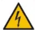 | CAUTION! Warning of electric shock! |
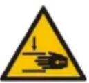 | CAUTION! Danger of crushing your hand!! |
 | Caution! Hot surface can cause burns! |
| For indoor use only. | |
| CAUTION! Do not use this unit near bathtubs, showers, sinks and other vessels containing water. | |
| During operation, the unit generates an electromagnetic field around it, which may cause medical implants, i.e. pacemakers, etc., to malfunction. |

CAUTION! The illustrations in this instruction manual are for reference only and may differ from the actual product in some details.
2. Safety of use
CAUTION! Read all safety warnings and all instructions. Failure to follow the warnings and instructions may result in electric shock, fire and/or severe personal injury or death.
The term "unit" or "product" in the warnings and in the description of the instructions refers to the INFRARED PAINT DRYER
1.1. Electrical safety
a) The plug of this unit must fit into the outlet. Do not modify the plug in any way. Original plugs and matching outlets reduce the risk of electric shock.
b) Avoid touching grounded parts, such as pipes, heaters, ovens, and refrigerators. There is an increased risk of electric shock if your body is grounded and touches the unit exposed to direct rain, wet pavement, and operation in a humid environment. If water enters the unit, there is an increased risk of damage to the unit and electric shock.
c) Do not touch the unit with wet or damp hands.
d) Do not use the cord in an unintended manner. Never use it to carry the unit or to pull the plug out of the socket. Keep the cord away from heat sources, oil, sharp edges or moving parts. Damaged or tangled cords increase the risk of electric shock.
e) Do not use the unit if the power cord is damaged or shows signs of wear. A damaged power cord should be replaced by a qualified electrician or the manufacturer's service department.
f) To avoid electric shock, do not immerse the cable, plug, or unit itself in water or other liquid. Do not use the unit on wet surfaces.
g) CAUTION - THREAT TO LIFE! When cleaning or using the unit, never immerse it in water or other liquids.
h) Do not use the unit in rooms with very high humidity / in the immediate vicinity of water tanks!
i) Do not allow the machine to get wet. Risk of electric shock!
1.2. Safety in the workplace
a) Keep the work area tidy and well lit. Disorder or poor lighting can lead to accidents. Be foresighted, watch what you are doing and use common sense when using the unit.
b) Do not use the unit in an explosive area, for example in the presence of flammable liquids, gases or dust. The unit produces sparks that can ignite dust or fumes.
c) If you find any damage or irregularities in the operation of the unit, immediately turn it off and report it to an authorized person.
d) Only the manufacturer's service department may repair the unit. Do not carry out repairs yourself!
e) If you have any doubts as to whether the product is working properly or if it is damaged, contact the manufacturer's service department.
f) Only the manufacturer's service department can repair the unit. Do not carry out repairs yourself!
g) In case of open flames or fire, use only dry powder or snow (CO2) fire extinguishers to extinguish the live equipment.
h) No children or unauthorized persons are allowed in the work area. (Inattention may result in loss of control of the unit.)
i) Use the unit in a well-ventilated area.
j) Check the condition of the safety stickers regularly. Replace them if they are illegible.
k) Keep these instructions for use for future reference. If the unit is to be passed on to a third party, the operating instructions must also be handed over together with the unit.
I) Keep the packaging and small assembly parts out of the reach of children.
m) Keep the unit away from children and animals.
n) When using this unit together with other units, also follow the other instructions for use.
o) Make sure that the unit is placed on a flat and stable surface.
⚠️Please note! Keep children and other bystanders safe while operating the unit.
1.3. Personal safety
a) Do not operate this unit if you are tired, ill or under the influence of alcohol, drugs or medication that could impair your ability to operate the unit.
b) The unit may be operated by persons who are physically fit, capable of operating it and appropriately trained, and who have read this instruction manual and have been trained in occupational safety and health.
c) The unit may be operated by persons who are physically fit, capable of operating it and appropriately trained, and who have read this instruction manual and have been trained in occupational safety and health.
d) Use caution and common sense when operating this unit. A moment's inattention during operation may result in serious personal injury.
e) To prevent accidental start-up, make sure the switch is in the off position before connecting to a power source.
f) Do not overestimate your capabilities. Maintain body balance and equilibrium at all times during operation. This allows for better control of the machine in unexpected situations.
g) The unit is not a toy. Children should be watched to ensure that they do not play with the unit.
h) Risk of burns - during operation some parts of the unit get hot and even after switching off they remain hot for some time.
1.4. Safe use of the unit
a) Do not use the unit if the ON/OFF switch does not function properly (does not turn on and off). Units that cannot be controlled by the switch are unsafe, cannot operate, and must be repaired.
b) Unplug the unit before making adjustments, changing accessories, or putting it away. This precaution reduces the risk of accidental start-up.
c) Keep unused equipment out of the reach of children and out of the reach of anyone unfamiliar with the unit or this instruction manual. These units is dangerous in the hands of inexperienced users.
d) Keep the unit in good working condition. Check before each use for general damage or damage to moving parts (cracks in parts and components or any other condition that may affect the safe operation of the unit). If damaged, have the unit repaired before use.
e) Keep the unit out of the reach of children.
f) Repairs and maintenance should be carried out by qualified personnel using only original spare parts. This will ensure the safety of use.
g) When transporting or moving the unit from storage to the place of use, observe the health and safety rules for manual handling applicable in the country where the unit is used.
h) Do not leave the unit switched on unattended.
i) Clean the unit regularly to prevent permanent dirt build-up.
j) Do not tamper with the unit to alter its performance or design.
k) Keep the unit away from sources of fire and heat.
I) Do not overload the unit.
m) Do not block the ventilation openings of the unit!

CAUTION! Although the product has been designed to be safe, with adequate safeguards, and despite the additional safety features provided to the user, there is still a slight risk of accident or injury when handling the unit. You are advised to use caution and common sense when using this product.
3. Rules of use
The product is designed for drying surfaces in paint repairs (putties, primers and topcoats) thanks to short waves of infrared radiation. The use of a unit operating on this principle reduces time and costs in sheet metal and paint repairs, especially local ones.
The user is responsible for any damage resulting from misuse.
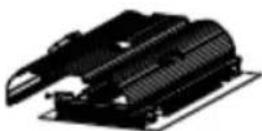
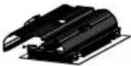
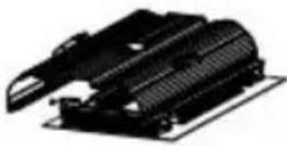
3.1. Description of the unit
A. Cassette
B. Cassette bracket
C. Bracket actuator
D. Control panel
E. Power switch (ON/OFF)
F. Handle for moving
G. Column
H. Base
I. Swivel wheel (x4)
3.2. Preparation for operation
POSITIONING OF THE UNIT
The ambient temperature must not exceed 40^ C and ambient humidity should not exceed 95%. Place the unit in a way that ensures good air circulation, on a dry, stable surface, in an upright position so that it does not move by itself during operation. Maintain a minimum clearance of 10 cm from any wall of the unit. Always keep the
unit out of reach of children and persons with reduced mental, sensory or intellectual functions. Place the unit in such a way that the mains plug can be reached at any time. Ensure that the power supply to the unit corresponds to that specified on the identification plate!
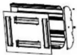
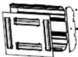
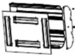
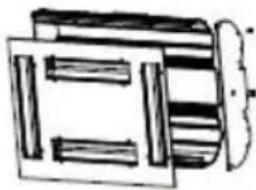
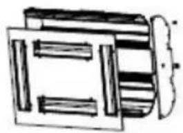
MOUNTING THE UNIT (see the assembly drawing below)
The supplied unit is divided into 3 segments that need to be assembled together - the base, the column and the cassette.
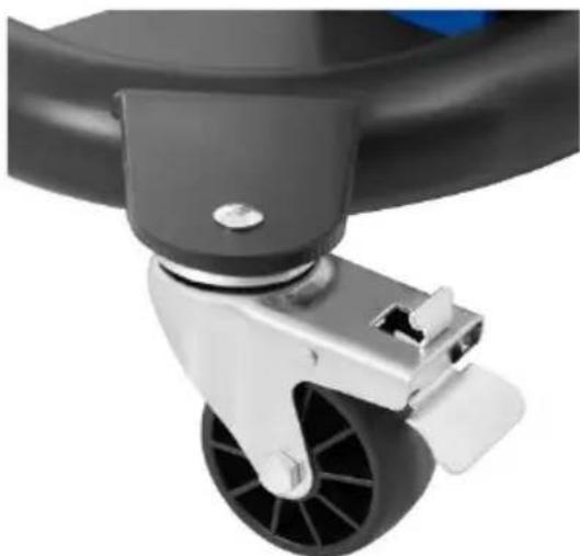
First, assemble the 4 wheels to the base, where the wheels with a brake should be at the rear (closer to the column) of the unit.
natural_image
Close-up of a black and silver bicycle steering wheel with a blue head (no text or symbols visible)Then mount the column to the base by placing it on the base and screwing them together with screws. On the column, mount the cassette support arm, and then the actuator that supports the operation of the cassette arm. In the end, on the bracket mount the cassette by tightening it with screws.
natural_image
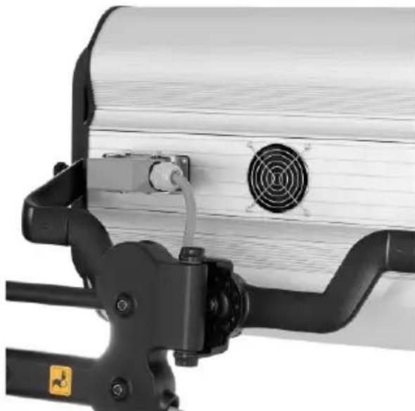
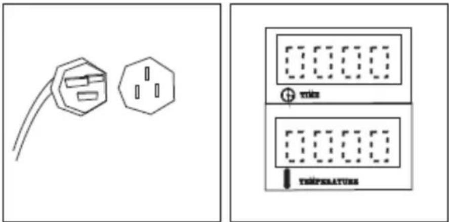
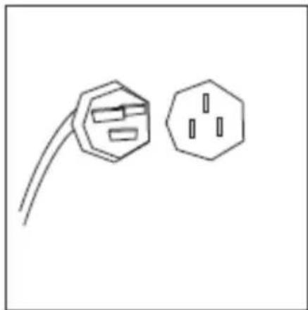
Close-up of a mechanical device with a circular vent and lever mechanism (no visible text or symbols)Finally, connect the power cable of the cassette with the column - the socket is located on the back of the cassette housing (see the above picture).
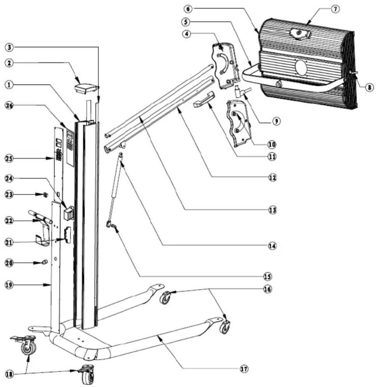
| Number | Name |
| 1 | Column |
| 2 | Top cover |
| 3 | Plastic tape |
| 4 | Connector (left) |
| 5 | Cassette bracket |
| 6 | Clamp |
| 7 | Cassette |
| 8 | Nut |
| 9 | Connecting rod |
| 10 | Connector (right) |
| 11 | Handle |
| 12 | Lower connecting rod |
| 13 | Upper connecting rod |
| 14 | Actuator (gas spring) |
| 15 | Actuator mounting |
| 16 | Wheel (x2) |
| 17 | Base |
| 18 | Wheel with brake (x2) |
| 19 | Bottom housing |
| 20 | Residual current circuit breaker |
| 21 | Thyristor module |
| 22 | Handle |
| 23 | Power switch |
| 24 | Transformer |
| 25 | Upper housing |
| 26 | Printed circuit board |
3.3. Working with the unit
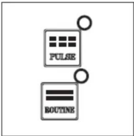
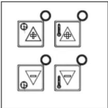
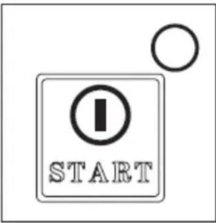
3.3.1 Control panel
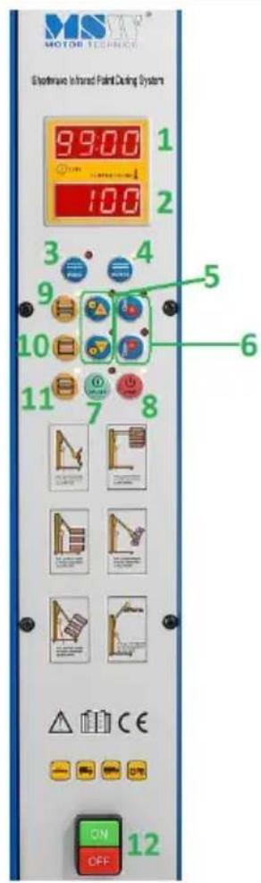
- Time display
- Temperature display
- Pulse mode button
- Standard mode button
- Time setting buttons
- Temperature setting buttons
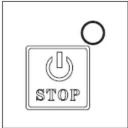
- START button
- STOP button
9-10-11. Buttons for selecting a particular lamp - Power switch (ON/OFF)
3.3.2 Setup and use
IMPORTANT: the surface to be heated should be clean and dry.
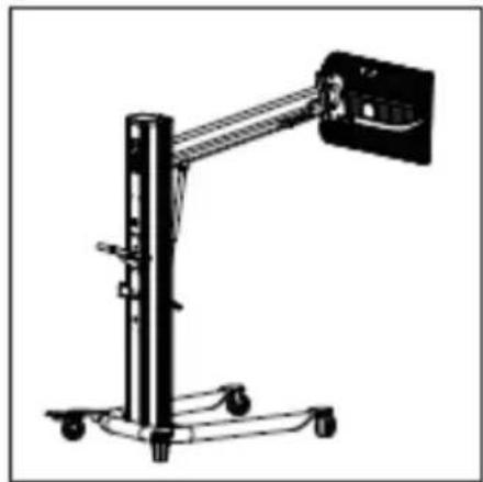
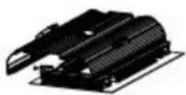
a) Set the radiant heater in the given place, adjust the position of the cassette parallel to the surface to be heated, so that the distance of the lamps from the surface is within 30 - 60 ~cm . Lock the brakes in the wheels.
natural_image
Mechanical device with articulated arm and wheels (no visible text or symbols)
b) Connect the unit to the power outlet and press the "ON" button (12), and the display on the control panel will show the temperature and the time of warming.
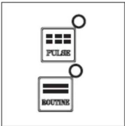
c) Select with the appropriate button (3 or 4) the mode of operation of the unit - "Routine" (standard) or "Pulse" (pulse - for the effect of greater surface gloss).
d) Set with buttons 5 and 6 the temperature and the heating time.
e) Press the START button to start warming.
f) When the warming is completed, press the "STOP" button.
g) If the unit is not used any more, turn off the power by pressing the "OFF" button (12) and, if necessary, pull the plug from the power socket.
natural_image
Simple line drawing of an electrical outlet with two hexagonal connectors (no text or symbols)3.4. Cleaning and maintenance
a) Pull the mains plug and let the unit cool down completely before cleaning, adjusting or replacing accessories and when the unit is not in use.
b) Use only non-corrosive cleaning agents for cleaning the surfaces.
c) Store the unit in a dry and cool place protected from moisture and direct sunlight. For extra protection, you can cover the unit, but only when completely cooled!
d) Do not spray the unit with a stream of water or immerse it in water.
e) Make sure that no water enters through the ventilation openings in the casing.
f) Clean the ventilation openings with a brush and compressed air.
g) Use a soft cloth for cleaning.
h) Do not use sharp and/or metal objects (e.g. a wire brush or metal spatula) for cleaning, as these may damage the surface of the material from which the unit is made.
i) Do not clean the unit with acidic substances, medical products, diluent, fuel, oil or other chemicals as this may cause damage to the unit.
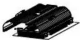
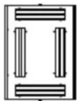
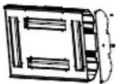
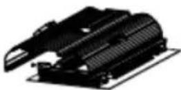
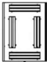
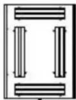
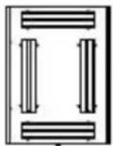
3.4.1 Replacing lamps in the cassette
(1)
natural_image
Simple line drawing of a rectangular container with internal compartments and a curved arrow indicating direction (no text or symbols)(2)
natural_image
Simple line drawing of a mechanical component with no text or symbols(3)
(4)
(5)
CAUTION: try not to touch the lamp with bare hands - however, in case contact occurs, the lamp should be wiped gently with a soft cloth soaked in alcohol or white spirit.
- Prepare the cassette for lamp replacement - it should be disconnected from the power supply (unplugged from the socket) and completely cooled down.
- Remove the screws on the side panels of the cassette housing.
- Remove the screws on the front panel of the cassette housing.
- Unscrew the screws on both ends of the respective lamp in the cassette to remove it.
- To install a new lamp, repeat the above steps in reverse order.
DISPOSAL OF USED UNITS.
At the end of its useful life, this product should not be disposed of with normal household waste but should be taken to a collection point for the recycling of electrical and electronic equipment. This is indicated by the symbol on the product, operating instructions or packaging. The materials used in this unit are recyclable according to their marking. You will be making an important contribution to protecting our environment by reusing, recycling or otherwise disposing of used units.
Your local administration will provide you with information about the appropriate disposal point for used units.
TROUBLESHOOTING
| Problem | Possible cause | Action |
| The cassette does not work | a) Defective lampsb) Unconnected cassettec) Defective thyristor module | a) Check lampsb) Check cassette connectionc) Check thyristor module |
| The radiator does not switch off | a) Defective thyristor module | a) Check thyristor module |
| Display shows nothing or displays incomplete information | a) Disconnected flat wire on control boardb) Defective display | a) Check flat cable connectionb) Check the display |
| Time and temperature cannot be set | a) Defective buttonsb) No connection to the pushbutton board | a) Check the connection of the buttonsb) Check if there is current to the board |
natural_image
Close-up of a black and silver hover key with visible wheels and adjustment knobs (no text or symbols)natural_image
Close-up of a mechanical device with a circular vent and lever mechanism (no visible text or symbols)natural_image
Simple line drawing of an electrical outlet with two hexagonal connectors (no text or symbols)natural_image
Simple line drawing of a rectangular container with internal compartments and a side outlet (no text or symbols)(2)
natural_image
Simple line drawing of a mechanical component or housing (no text or symbols)(3)
(4)
(5)
natural_image
Close-up of a black and silver bicycle steering wheel with a blue head (no text or symbols visible)natural_image
Close-up of a mechanical device with a circular vent and lever mechanism (no visible text or symbols)natural_image
Mechanical device with articulated arm and wheels (no visible text or symbols)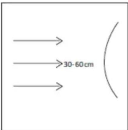
natural_image
Simple line drawing of two connected electrical plugs (no text or symbols)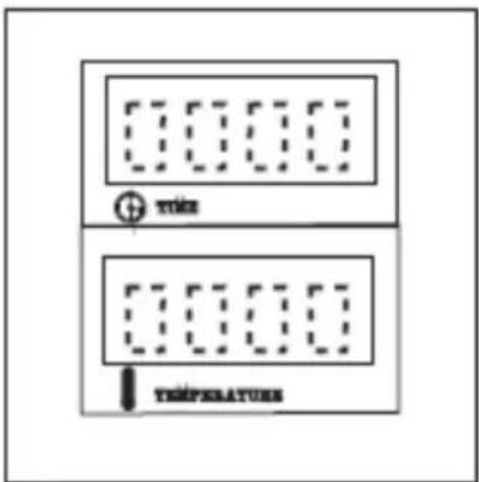
natural_image
Simple line drawing of an open electrical plug with two terminals (no text or symbols)3.4. ČISTĚNÍ A ÚDRŽBA
natural_image
Simple line drawing of a rectangular device with internal compartments and a handle (no text or symbols)(2)

natural_image
Simple line drawing of a mechanical component or housing (no text or symbols)(3)
(4)
(5)
natural_image
Close-up of a black and silver bicycle control lever with visible wheels and adjustment knobs (no text or symbols)natural_image
Close-up of a mechanical device with a circular vent and lever mechanism (no visible text or symbols)natural_image
Simple line drawing of an electrical outlet with a bulb and two internal slots (no text or symbols)natural_image
Simple line drawing of a rectangular container with internal compartments and a curved arrow indicating direction (no text or symbols)(2)
natural_image
Pure mechanical component diagram without any text, numbers, or symbols(3)

(4)

(5)
natural_image
Close-up of a black and silver bicycle steering wheel with a blue head (no text or symbols visible)natural_image
Close-up of a mechanical device with a circular vent and lever mechanism (no visible text or symbols)natural_image
Simple line drawing of an electrical outlet with two hexagonal shapes and wires (no text or symbols)natural_image
Simple line drawing of a rectangular container with internal compartments and a curved side (no text or symbols)(2)

natural_image
Simple line drawing of a mechanical component or housing (no text or symbols)(3)
(4)
(5)
natural_image
Close-up of a black and silver bicycle steering wheel with a blue head (no text or symbols visible)natural_image
Close-up of a mechanical device with a circular vent and lever mechanism (no visible text or symbols)natural_image
Simple line drawing of an electrical outlet with two hexagonal connectors (no text or symbols)natural_image
Simple line drawing of a rectangular container with internal compartments and a side outlet (no text or symbols)(2)
natural_image
Pure mechanical component diagram without any text, numbers, or symbols(3)
(4)
(5)
natural_image
Close-up of a black and silver hover key with visible wheels and adjustment knobs (no text or symbols)natural_image
Close-up of a mechanical device with a circular vent and lever mechanism (no visible text or symbols)natural_image
Simple line drawing of a rectangular container with internal compartments and a curved arrow indicating rotation (no text or symbols)(2)

natural_image
Pure mechanical component diagram without any text, numbers, or symbols(3)

(4)

(5)
A. Kassette
B. Kassettebeslag
C. Beslag aktuator
D. Kontrolpanel
E. Strømafbryder (ON/OFF)
F. Håndtag til flytning
G. Søjle
H. Produktets bund
I. Drejehjul (x4)
APPARATETS PLACERING
natural_image
Close-up of a black and silver bicycle steering wheel (no text or symbols visible)natural_image
Close-up of a mechanical device with a circular vent and attached black tool (no visible text or symbols)natural_image
Mechanical device with articulated arm and wheels (no visible text or symbols)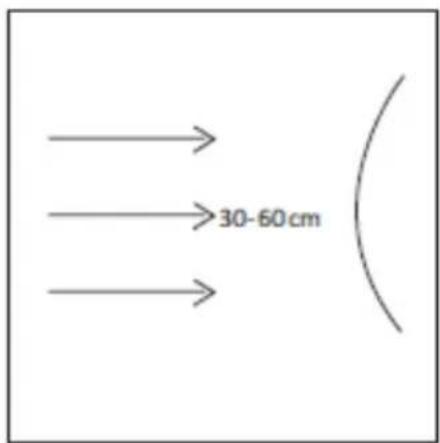
b) Tilslut enheden til stikkontakten og tryk på "ON"-knappen (12), og displayet på kontrolpanelet vil vise temperaturen og tidspunktet for opvarmning.

c) Vælg med den relevante knap (3 eller 4) enhedens driftstilstand - "Rutine" (standard) eller "Pulse" (puls - for effekten af større overfladeglans).
natural_image
Simple line drawing of an electrical outlet with two hexagonal connectors (no text or symbols)natural_image
Simple line drawing of a rectangular container with internal compartments and a handle (no text or symbols)(2)

natural_image
Simple line drawing of a mechanical component or housing (no text or symbols)(3)
(4)
(5)
For the disposal of the device please consider and act according to the national and local rules and regulations.
CONTACT
expondo Polska sp. z o.o. sp. k.