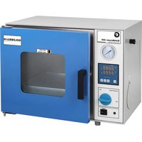
450 - Oven Goldbrunn - Free user manual and instructions
Find the device manual for free 450 Goldbrunn in PDF.


User questions about 450 Goldbrunn
0 question about this device. Answer the ones you know or ask your own.
Ask a new question about this device
Download the instructions for your Oven in PDF format for free! Find your manual 450 - Goldbrunn and take your electronic device back in hand. On this page are published all the documents necessary for the use of your device. 450 by Goldbrunn.
USER MANUAL 450 Goldbrunn
natural_image
Exterior view of a laboratory incubator with digital display and control panel (no visible text or symbols)
natural_image
Blue laboratory incubator with control panel and digital display (no visible text or symbols)
PLEASE NOTE! Drawings in this manual are for illustration purposes only and in some details may differ from the actual machine.
The original instruction manual is in German. The versions in other languages are translations from German.
General safety information for the use of electrical devices:
To avoid injury from fire or electric shock, please ensure compliance with safety instructions when using this device. Please read the instruction carefully and make sure that you have understood it well. Keep the manual near the equipment to be able to read it at any time. Always use properly grounded current sources providing the necessary voltage (indicated on the device's label). If you have any doubt, let an electrician check that your outlet is properly grounded. Never use a damaged power cable. Do not open the unit in a damp or wet environment, or if your hands or body are damp or wet. Protect the unit of solar radiation. Use the device in a protected location to avoid damaging the equipment or endangering others. Make sure the device is able to cool and avoid placing it too close to other devices that produce heat. Before cleaning, disconnect it. Use a soft damp cloth for cleaning. Avoid using detergent and make sure that no liquid enters the unit. No internal element of this device needs to be maintained by the user. An opening of the device without our approval leads to a loss of warranty.
2. GENERAL INFORMATION REGARDING SAFETY
This section of the manual contains all security aspects and ensures the best warranty protection as well as safe and smooth operation if complied to. Non-compliance with safety instructions in this manual or improper use or misuse can lead to situations in which the device will be a threat. Knowledge of the recommendations contained in this manual is the basis for avoiding such situations and ensuring reliable and safe operation. At the risk of losing the warranty, it is forbidden to make any unauthorized repairs or alterations to the device itself. In cases where intervention is needed inside the device, please contact the manufacturer.
Before installing and operating the device you must check the mains voltage guidelines as well as the actual current. Use the device only if the power supply voltage corresponds with the guidelines given for the device. Follow the recommendations on health and safety of this manual as well as safety guidelines and regulations for the protection of the environment, specific and applicable to the place of use.
• The device may not be used by:
• people with physical or mental disabilities
- children
• people with insufficient experience, and/or insufficient knowledge;
EN
- This manual should be kept near the device. In case of passing or selling the device, the manual should also be handed over with the device.
- Everyone operating the device must abide by the guidelines contained in this manual and follow all safety regulations.
- The device is designed to work only in enclosed areas.
Safe operation is ensured only in the conditions of use in accordance with its intended purpose.
Any work related to the installation, maintenance or repair of the device must be carried out by a qualified service technician.
3. DEVICE INSTALLATION AND MAINTENANCE
Proper connection of the device to an adequate socket with earthing is the foundation for proper work. In the case of inappropriate installation, the machine may cause injury.
- The cable must not come into contact with sources of heat and sharp edges. The cable must not sag and cannot be immersed in water.
- Do not use malfunctioning or damaged devices.
- Parts or accessories not recommended by the manufacturer cannot be used in the device. The act of using parts not recommended by the manufacturer results in loss of warranty and can lead to a direct threat to the life or health of the user.
- It is forbidden to move, adjust and rotate the device during operation.
- Remove all packaging materials before use.
- The device should be placed on a flat, stable surface which can support its weight.
- It is forbidden to place the device on a combustible surface.
- It is forbidden to place the device near an open flame, electric stoves, coal stoves or other heat sources, as well as near direct sunlight.
- The device should be placed to ensure good air circulation. A minimum distance of 20 cm to the rear wall, 15 cm to the sides and 35 cm upwards must be maintained.
- It is forbidden to place the device in areas with high humidity.
- The device must not be connected to outlets other than wall-mounted sockets, do not use a multiple outlet adapter or multiple sockets.
4. GENERAL SAFETY GUIDELINES FOR OPERATION OF VACUUM DRYERS:
Regularly inspect the condition of the doors and safety windows for scratches or other damage. In the case of finding any damages on the doors or windows, do not generate vacuum in the device. This also applies to the other functional elements of the device – pipe connectors, switches, etc.
EN
Do not put the vacuum dryer on a flammable ground!
It is important for the vacuum dryer to be precisely vertical. The distance between the back of the dryer and the wall should be at least 20 cm. The distance between the top of the device and the ceiling should be at least 35 cm, whereas the minimum distance between the sides of the device and the walls should be at least 15 cm on each side. Ensure good ventilation in the room in which the device is used.
It is forbidden to use the device in rooms containing flammable or explosive gas mixtures. The device is not explosion-proof. Turning the device on or off may generate ignition/explosion caused by electric arch which forms in the master switch of the device.
When turning the vacuum dryer on for the first time, ensure constant supervision over operation of the device until the time of achieving stable working conditions.
In order to prevent serious damage of the vacuum dryer load, the dryer itself and its surroundings, pay particular attention to the physical and chemical conditions (e.g. flash point) of the dryer load. The vacuum dryer is not explosion-proof and therefore it cannot be used to dry, vaporize or bake paints, enamels or other materials the reagents of which may form an explosive mixture with air.
It is inadmissible for flammable gas or flammable gas and air mixture to form in the vacuum dryer chamber or its immediate vicinity.
Large amounts of dusts or caustic vapours inside the vacuum dryer chamber or near the device may generate deposits inside the device and cause a short-circuit or damage the electronic components. Therefore, it is important to take all the appropriate precautions regarding excessive deposits of dusts or caustic vapours inside and outside the device.
In order to ensure proper air circulation in the vacuum dryer chamber, provide sufficient gaps between the load and the inside chamber walls. Do not place any load on the bottom, side walls or under the ceiling of the chamber.
In the case of any problems, such as smoke or unusual odour coming from the device, turn it off immediately and disconnect the power supply. In such a case, contact the service centre. Failure to do so may cause fire or electric shock. Never attempt to repair the device yourself.
Do not use a coiled or tangled supply cable. A coiled or tangled supply cable may overheat and cause fire. Do not pull, twist or stretch the cable. This may cause an electric shock. Do not yank or pull the cable to disconnect the power supply. Place the cable away from heat sources, oil tanks and sharp edges.
Do not dismantle or modify the device. It may cause a risk of electric shock or fire. Never touch the door or the window during or immediately after operation of the device. High temperature may cause serious burns.
During a thunderstorm turn the device off and disconnect it from power supply.
5. BEFORE FIRST USE - DEVICE CHECKING, TRANSPORT AND STORAGE

Upon receipt of the goods, check the packaging for integrity and open it. If the packaging is damaged, please contact your transport company and distributor within 3 days, and document the damages as detailed as possible. Do not turn the package upside down! When transporting the package, please ensure that it is kept horizontal and stable. Please keep all packaging materials (cardboard, plastic tapes and styrofoam), so that in case of a problem, the device can be sent back to the service centre in accurate condition. The package should be closed until the installation of the device.
- TECHNICAL DETAILS
| Modell Goldbrunn 450 | Vacuum Dryer | Goldbrunn 1450Vacuum Dryer |
| Internal dimensions (chamber) (cm) 30 x 30 | x 27,5 41,5 x 37 x | 34,5 |
| External dimensions (cm) 60,5 x 49 x 45 73 | x 56 x 55 | |
| Rated power 450 W 1450 W | ||
| Chamber volume 20 L 50 L | ||
| Rated voltage/frequency | 230 V / 50 Hz | |
| Working Temperature | 5 - 40 °C | |
| Working Humidity | ≤85 % | |
| Temperature range | 50~250°C | |
| Vacuum degree | 133 Pa | |
| Maximum leak rate | 0,01 bar / h | |
| Temperature regulator | PID | |
| Temperature unit | °C | |
| Temperature uniformity | +/- 0,9 °C | |
| Maximum heating range | 6~8 °C / min | |
| Time range | 1-9999 minutes | |
| Maximum negative pressure | 0.098 MPa28.93"Hg | |
| Vacuum range ratio | 0~-0.1 MPa0 to 29.52"Hg | |
| Vacuum pipe connector | Inside diameter 16 mm | |
| Inspection window | Double-glazed, tempered glass | |
| Safeguards | Integrated automatic circuit-breaker,overheat protection | |

7. DEVICE DESCRIPTIONS
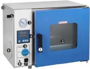
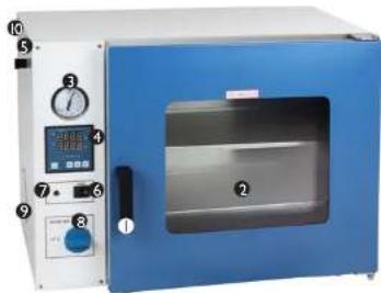
a. Goldbrunn 450 vacuum dryer
natural_image
Blue laboratory incubator with control panel and digital display (no visible text or symbols)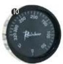
I. door handle
2 inspection window
3. vacuum gauge
4. control panel
5. inlet valve
6. vacuum valve
7. ON/OFF switch
8. indicator light
9. vacuum pump connection
10. temperature safety switch
⚠️ PLEASE NOTE! Device is equipped with temperature safety switch – it turns off power when temperature inside device exceeds temperature value set on the switch. In each case switch should be set to a temperature value of 10^ C higher than temperature set on main control panel.
b. Goldbrunn 1450 vacuum dryer
natural_image
Blue laboratory oven with control panel and digital display (no visible text or symbols)
EN
I. door handle
2 inspection window
3. vacuum gauge
4. control panel
5. inlet valve
6. ON/OFF switch
7. indicator light
8. vacuum valve / ON OFF
9. vacuum pump connection
10. temperature safety switch
c. Control panel (mutual for both devices):
text_image
TEMP PV 8.8.8.8 ① SV 8.8.8.8 ② RUN P 3 ALM SET ← ↓ ↑ 4 5 6 7⚠️ PLEASE NOTE! Device is equipped with temperature safety switch – it turns off power when temperature inside device exceeds temperature value set on the switch. In each case switch should be set to a temperature value of 10^ C higher than temperature set on main control panel.
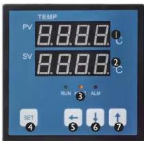
I. measured value display
2 preset value display
3. indicators:
RUN – operation indicator HEAT – heating indicator ALM – alarm indicator
- SET function key
- SHIFT key
- setting down button („-”)
- setting up button (,,+")
EN
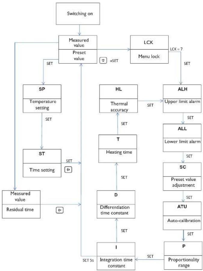
Procedure showing the course between the functions:
flowchart
graph TD
    A["Switching on"] --> B["Measured value"]
    B --> C["Preset value"]
    C --> D["LCK"]
    D --> E["Menu lock"]
    E --> F["ALH"]
    F --> G["Upper limit alarm"]
    G --> H["ALL"]
    H --> I["Lower limit alarm"]
    I --> J["SC"]
    J --> K["Preset value adjustment"]
    K --> L["ATU"]
    L --> M["Auto-calibration"]
    M --> N["P"]
    N --> O["Proportionality range"]
    C --> P["SET"]
    P --> Q["SP\nTemperature setting"]
    Q --> R["SET"]
    R --> S["ST\nTime setting"]
    S --> T["SET"]
    T --> U["Measured value\nResidual time"]
    U --> V["SET 5s"]
    V --> W["I\nIntegration time constant"]
    W --> X["D\nDifferentiation time constant"]
    X --> Y["D\nTemperature setting"]
    Y --> Z["SET"]
    Z --> AA["HL\nThermal accuracy"]
    AA --> AB["T\nHeating time"]
    AB --> AC["SET"]
    AC --> AD["SET"]
    AD --> AE["SET"]
    AE --> AF["SET"]
    AF --> AG["SET"]
    AG --> AH["SET"]
    AH --> AI["SET"]
    AI --> AJ["SET"]
    AJ --> AK["SET"]
    AK --> AL["SET"]
    AL --> AM["SET"]
    AM --> AN["SET"]
    AN --> AO["SET"]
    AO --> AP["SET"]
    AP --> AQ["SET"]
    AQ --> AR["SET"]
    AR --> AS["SET"]
    AS --> AT["SET"]
    AT --> AU["SET"]
    AU --> AV["SET"]
    AV --> AW["SET"]
    AW --> AX["SET"]
    AX --> AY["SET"]
    AY --> AZ["SET"]
    AZ --> BA["SET"]
    BA --> BB["SET"]
    BB --> BC["SET"]
    BC --> BD["SET"]
    BD --> BE["SET"]
    BE --> BF["SET"]
    BF --> BG["SET"]
    BG --> BH["SET"]
    BH --> BI["SET"]
    BI --> BJ["SET"]
    BJ --> BK["SET"]
    BK --> BL["SET"]
    BL --> BM["SET"]
    BM --> BN["SET"]
EN
When the temperature controller is on, the PV display shows the value of measured temperature, and the SV display shows the preset temperature value.
Basic settings:
Temperature setting: Press the SET button, the PV display shows „SP” the SV displays shows the adjustable temperature value. When last digit blinks, set its value with the and buttons. Use the button to switch to the next digit and set its value using i and j
After setting the temperature, press the SET button to set the timer.
Timer setting: Press the SET button, the PV display shows „SI“ the SV displays shows the adjustable timer value. When last digit blinks, set its value with the 1 and 1 buttons. Use the "button to switch to the next digit and set its value using and .
After setting the time, press the SET button for the device to start operation with the defined parameters.
Advanced settings:
CAUTION: All the controllers and parameters have been thoroughly tested and set by the manufacturer. If the functional parameters of the vacuum dryer meet your expectations and if the vacuum dryer runs properly, there is no need to modify these parameters.
How to open the advanced settings:
Press and hold ! then press SET. The display will show „LCK”. Release the SET button (while pressing 0) and set the value of the blinking digit to „7”. Release and press SET. The display will show „ALH”.
ALH – upper temperature limit alarm – set the desired value using 1 and 1. The device will set off an alarm when the sum of the preset and upper limit temperature exceeds the actual temperature value. Available values: range of 0 to 100°C.
After setting the upper temperature limit alarm value press SET in order to adjust the lower temperature limit alarm – the display will show "ALL"
EN
ALL – lower temperature limit alarm – set the desired value using 1 and 1 . The device will set off an alarm when the sum of the preset and upper limit temperature is lower than the actual temperature value. Available values: range of 0 to 100°C.
After setting the lower temperature limit alarm value, press SET in order to adjust the measured temperature value "SC".
SC – measured temperature value adjustment – the PV display shows the adjusted temperature value. Available values: -50^ to +50^ .
After setting the measured temperature adjustment value, press SET in order to adjust the PID controller self-regulation – the display shows "ATU".
ATU – enable or disable self-regulation of the PID controller – available values: „0” – PID self-regulation disabled; „1” – PID self-regulation enabled. When this parameter is set to „1”, the device can be started in self-regulation mode. In order to start the self-regulation mode, leave the advanced settings and, in the normal operation mode, press and hold for about 5 seconds. When this mode is on, the SV displays blinks and shows „ATU”. During this process the actual temperature may differ from the preset one – this is normal. The duration of the self-regulation function is about 3 to 5 minutes. After this time the PID controller will adjust its settings, in order to work more precisely.
After setting, press SET in order to adjust the proportionality range "P".
P – proportionality range – heating control adjustment. Available values: from 0 to 400.0
After setting, press SET in order to adjust the integration time constant "P".
I – integration time constant. Available values: from 0 to 2000
After setting, press SET in order to adjust the differentiation time constant "d".
d - differentiation time constant. Available values: from 0 to 1000
After setting, press SET in order to adjust the heating period "P".
T – heating time. Available values: from 1 to 60
After setting, press SET in order to adjust the thermal accuracy control range "HL".
HL – thermal accuracy control range. Available values: from 500 to 1.500
After setting, press and hold SET for about 5 seconds in order to leave the advanced settings and save the changes.

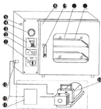
- PICTORIAL DIAGRAM
text_image
Technical diagram of an oven with numbered components and labeled partsI. vacuum valve
2 ON/OFF master switch
3. temperature regulator
4. vacuum gauge
5. air inlet valve
6. door
7. door handle
8. inspection window
9. shelves
10. vacuum pump (excluded from the delivery)
II. dryer (optional)
12. vacuum pump connection pipe
13. vacuum pump connection valve
10. REGULAR CONTROL OF THE DEVICE
Control regularly that the device doesn't present any damage. If there is any damage, please stop using the device. Please contact your customer service to solve the problem. What to do in case of a problem?
Please contact your customer service and prepare following information:
- Invoice number and serial number (the latter is to be found on the technical plate on the device).
- If relevant, a picture of the damaged, broken or defective part.
CAUTION: Never open the device without the authorization of your customer service. This can lead to a loss of warranty!

II. TROUBLESHOOTING
| Problem Possible cause | Proposed solution | |
| No power supply | No voltage in the supply cable | Inspect the supply cable |
| The supply cable plug is incorrectly plugged into the power socket. The supply cable is damaged. | Plug the supply cable into the mains in a correct manner. Repair damaged cable. | |
| Blown fuse | Replace the fuse | |
| The PV display shows "☐☐☐☐" | Temperature sensor damaged or improperly connected | Replace or reconnect the temperature sensor |
| Temperature does not increase | Setting value too low | Set appropriate temperature value of at least RT+10°C (RT - ambient temperature) |
| Temperature controller damaged | Replace the temperature controller | |
| Heater damaged | Replace the heater | |
| Incorrect values of timer settings | Set ST=0 or ST=heating time + temperature time constant | |
| Vacuum does not appear in the chamber | Wrong pump selected | The vacuum generation speed should be 2 l/s |
| Faulty connection between the pump and the dryer | Inspect/replace connecting elements | |
| Vacuum meter damaged | Replace the vacuum meter | |
| Door closed improperly | Adjust the door locking pin in the closed position | |
| Door seal no longer flexible | Replace the seal | |
| Air inlet valve and vacuum valve are in wrong position | Put the valves in correct positions |
IPL

natural_image
Exterior view of a laboratory incubator with blue hood and control panel (no visible text or symbols)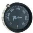
natural_image
Blue laboratory incubator with control panel and digital display (no visible text or symbols)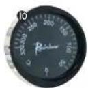
PL
text_image
Technical diagram of an oven with numbered components and labeled partsI. zawór próżniowy
natural_image
Solid mustard yellow background with no text, symbols, or patternsIT
natural_image
Exterior view of a laboratory incubator with digital display and control panel (no visible text or symbols)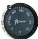
natural_image
Blue industrial oven with control panel and digital display (no visible text or symbols)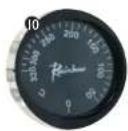
natural_image
Exterior view of a laboratory incubator with blue casing and control panel (no visible text or symbols)natural_image
Blue laboratory incubator with control panel and digital display (no visible text or symbols)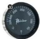
text_image
Technical diagram of an oven with numbered components and labeled partsnatural_image
Exterior view of a blue laboratory incubator with control panel and digital display (no visible text or symbols)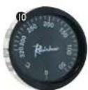
natural_image
Blue laboratory oven with control panel and digital display (no visible text or symbols)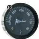
ES
text_image
Technical diagram of an industrial oven with numbered components and control panel labelsI. válvula de vacío
natural_image
Exterior view of a blue laboratory incubator with control panel and display (no visible text or symbols)natural_image
Blue laboratory incubator with control panel and digital gauges (no visible text or labels)text_image
Technical diagram of an oven with numbered components and labeled partsNAMEPLATE TRANSLATIONS
NOTES/NOTIZEN
| 1 Manufacturerexpondo Polska sp. z o.o. sp. k.ul. Nowy Kisiellin-Innowacyjna 7, 66-002 Zielona Góra | GOLDBRUNN THERM |
| 2 VACUUM DRYER | |
| 3 Model |  |
| 4 Voltage 230V~/50Hz | |
| 5 Temperature range 50-250°C | |
| 6 Vacuum degree ≤ 133 Pa | |
| 7 Power | |
| 8 Serial-No. | |
| 9 Production year | expondo.com |
| 12345 | ● | ● | ● | ● | |
| EN Manufacturer Product Name: Model Voltage Temperature range | |||||
| PL Producent Nazos produktu Model Napiecie Zakres temperatur | |||||
| DE | Hersteller | Produktname | Modell | Spannung | Temperaturbereich |
| FR | Fabricant | Nom du produit | Mociele | Tension | Plage de température |
| IT | Produktore | Nome del prodotto | Modello | Tensione | Intervallo di temperatura |
| ES | Fabricante | Nombre del producto | Modelo | Voltaje | Rango de temperatura |
| CZ | Výrobce | Název výrobku | Model Jmenoviténapájeci napěti | Rozsah teploty | |
| 6 | 7 | 8 | 9 | ||
| EN | Vacuum degree | Power | Serial No. | Production Year | |
| PL | Stopień próżni | Moc | Numer serii | Rok produkcji | |
| DE | Vakuum | Leistung | Ordnungsnummer | Produktionsjahr | |
| FR | Chambre sous vide | Puissance | Numéro de serie | Année de production | |
| IT | Vuoto | Potenza | Numero di serie | Anno di produzione | |
| ES | Vado | Potencia | Número de serie | Año de produción | |
| CZ | Skříň: max. vakuum | Jmenovity výkon | Sériové číslo | Rok výroby | |
GOLDBRUNN THERM
NOTES/NOTIZEN
NOTES/NOTIZEN
For the disposal of the device please consider and act according to the national and local rules and regulations.
CONTACT
expondo Polska sp. z o.o. sp. k.