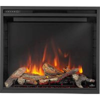
Woodland NEFI27H - Fireplace Napoleon - Free user manual and instructions
Find the device manual for free Woodland NEFI27H Napoleon in PDF.


User questions about Woodland NEFI27H Napoleon
0 question about this device. Answer the ones you know or ask your own.
Ask a new question about this device
Download the instructions for your Fireplace in PDF format for free! Find your manual Woodland NEFI27H - Napoleon and take your electronic device back in hand. On this page are published all the documents necessary for the use of your device. Woodland NEFI27H by Napoleon.
USER MANUAL Woodland NEFI27H Napoleon
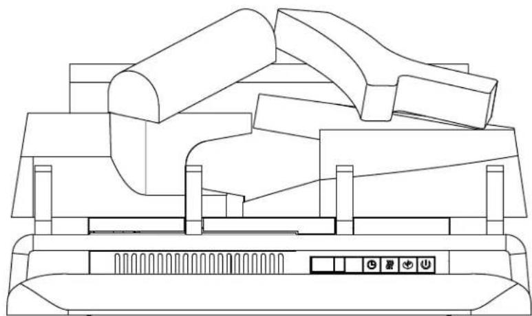
Woodland™ Electric Log Set
(NEFI24H illustrated)
natural_image
Line drawing of a 3D geometric sculpture with no text or symbolsSAFETY INFORMATION

WARNING
FIRE OR EXPLOSION HAZARD
If the information in these instructions are not followed exactly, a fire or explosion may result causing property damage, personal injury, or loss of life.
- Do not store or use gasoline or other fl ammable vapors and liquids in the vicinity of this or any other appliance.
INSTALLER:
Leave this manual with the appliance
CONSUMER:
Retain this manual for future reference


This appliance has a remote that requires button batteries that are hazardous to young children.
FOR INDOOR USE ONLY
CERTIFIED TO THE CANADIAN AND AMERICAN NATIONAL STANDARDS:
CSA 22.2 NO. 46 / UL 1278



C US
text_image
APPLY SERIAL NUMBER LABEL FROM CARTON Serial No. XXXXXX000000 MODEL NO.Wolf Steel Ltd., 24 Napoleon Rd., Barrie, ON, L4M 0G8 Canada / 103 Miller Drive, Crittenden, Kentucky, USA, 41030
Phone 1 (866) 820-8686 • www.napoleon.com • hearth@napoleon.com

WARNING
- If equipped with a heater, this appliance can be hot when operated and can cause severe burns if contacted.
- Do not operate appliance before reading and understanding operating instructions. Failure to operate appliance according to operating instructions could cause fire or injury.
- Do not install damaged, incomplete or substitute components.
- Do not burn wood or other materials in this appliance.
- All electric appliances have hot and arcing or sparking parts inside. Do not use it in areas where a gas line, paint or flammable liquids are present.
- Any safety screen or guard removed for servicing must be replaced prior to operating the appliance.
- It is imperative that the control compartments, circulating blower and its passageway in the appliance are kept clean. The appliance should be inspected before use and at least annually by a qualified service person. More frequent cleaning may be required due to excessive lint from carpeting, bedding material, etc. The appliance area must be kept clear and free from combustible materials, gasoline and other flammable vapors and liquids.
• Under no circumstances should this appliance be modified.
- Do not use this appliance if any part has been under water. Immediately call a qualified service technician to inspect the appliance and to replace any part of the control system which has been under water.
- If equipped with a glass door, do not operate the appliance with the glass door removed, cracked or broken. Replacement of the glass should be done by a licensed or qualified service person. Do not strike or slam shut the appliance glass door.
- Keep the packaging material out of reach of children and dispose of the material in a safe manner. As with all plastic bags, these are not toys and should be kept away from children and infants.
- Servicing should be done only while the appliance is disconnected from the power supply circuit.
• Always unplug appliance when not in use.
- Do not operate this appliance with a damaged cord or plug after the appliance malfunctions, has been dropped or damaged in any manner. Return appliance to authorized service facility for examination, electrical or mechanical adjustment, or repair.
- Do not use outdoors.
- When installing this appliance in a room where water is present, the installation must comply with codes recognizing the increased hazard of electrical shock and electrocution.
note:
This appliance is NOT suitable for installation in a bathroom.
- Do not run cord under carpeting. Do not cover cord with throw rugs, runners, or the like. Arrange cord away from traffic area and where it will not be tripped over.
- Connect to properly grounded outlets only.
- Do not insert or allow foreign objects to enter any ventilation or exhaust opening as this may cause an electric shock or fire, or damage the appliance.
- It is normal for your electric appliance to produce noise, especially when installed in a quiet space such as a bedroom.

WARNING
- To prevent a possible fire, do not block air intakes or exhaust in any manner. Do not use on soft surfaces, like a carpet, where openings may become blocked.
- Always plug appliances directly into a wall outlet/receptacle. Never use an extension cord or relocatable power tap (outlet/power strip).
- These appliances are tested and listed for use only with the optional accessories listed in these instructions. Use of optional accessories not specifically tested for this appliance could void the warranty and/or result in a safety hazard.
For appliances equipped with a heater:
- Risk of burns. Power to the appliance should be turned off and the appliance allowed to cool before servicing. To disconnect power to the appliance, turn controls to off, then remove plug from outlet.
- Young children should be carefully supervised when they are in the same room as the appliance. Toddlers, young children and others may be susceptible to accidental contact burns. A physical barrier is recommended if there are at risk individuals in the house. To restrict access to an appliance or stove, install an adjustable safety gate to keep toddlers, young children and other at risk individuals out of the room and away from hot surfaces.
- Clothing or other fl ammable material should not be placed on or near the appliance.
- Due to high temperatures, the appliance should be located out of traffic and away from furniture and draperies.
- Ensure you have incorporated adequate safety measure to protect infants/toddlers from touching hot surfaces.
• Even after the appliance is off, the glass and/or screen will remain hot for an extended period of time.
- Check with your local hearth specialty dealer for safety screens and hearth guards to protect children from hot surfaces. These screens and guards must be fastened to the floor.
- Ensure clearances to combustibles are maintained when building a mantel or shelves above the appliance. Elevated temperatures on the wall or in the air above the appliance can cause melting, discolouration or damage to decorations, a TV or other electronic components.

WARNING: This product can expose you to chemicals including lead and lead compounds, which are known to the State of California to cause cancer, and chemicals includ-BBP and DEHP, which are known to the State of California to cause birth defects or other productive harm. For more information, go to www.P65Warnings.ca.gov.
table of contents
1.0 general information 5
1.1 dimensions 5
1.2 listing approvals 5
1.3 general instructions 6
1.4 rating plate information 6
1.5 label location 7
1.6 locating the log set 7
1.7 grounding log set 7
2.0 installation 8
2.1 log set installation 8
2.1.1 installing log set into existing fireplace 8
2.1.2 installing log set into mantel 9
2.2 hard wiring installation 10
2.3 securing the log set 11
3.0 operating instructions
3.1 operating control panel 12
3.2 operating by remote control 13
3.3 remote Battery installation 13
4.0 finishing
4.1 NEFI24H log placement 14
4.2 NEFI27H log placement 14
4.3 ember bed placement 15
4.4 charcoal ember placement 16
5.0 wiring diagram
6.0 replacement parts
6.1 NEFI24H overview 19
6.2 NEFI27H overview 20
7.0 troubleshooting
8.0 warranty
9.0 service history 23
NOTE: Changes, other than editorial, are denoted by a vertical line in the margin.
Batteries must be disposed of according to the local laws and regulations. Some batteries may be recycled, and may be accepted for disposal at your local recycling center. Check with your municipality for recycling instructions.
1.1 dimensions
FRONT VIEW SIDE VIEW
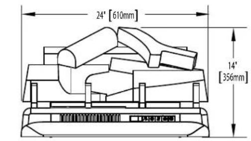
text_image
24° [610mm] 14° [356mm]NEFI24H ILLUSTRATED
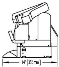
text_image
14" [356mm]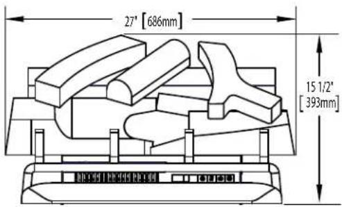
text_image
27" [686mm] 15 1/2" [393mm]NEFI27H ILLUSTRATED
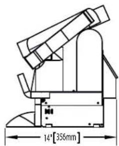
text_image
14" [356mm]1.2 listing approvals
This log set has been tested in accordance with the CSA Standards for fixed and location-dedicated electric room appliances in the United States and Canada. If you need assistance during installation, please contact your local dealer.
NOTE: This log set must be electrically wired and grounded in accordance with local codes or, in the absence of local codes, with National Electric Code ANSI/NFPA 70-latest edition in the United States or the Canadian Electric Code, CSA C22.1 in Canada.
| Model Number | NEFI24H NEFI27H | |
| Description | 24" Electric Logset Insert | 27" Electric Logset Insert |
| Voltage | 120V AC 120V AC | |
| Watts | Max 1500W Max 1500W | |
| Amps | 15 AMP Grounded Circuit | 15 AMP Grounded Circuit |
| Appliance Width | 24" (610mm) 27" (686mm) | |
| Appliance Height | 14"(356mm) | 15 1/2" (393mm) |
| Appliance Depth | 14" (356mm) 14" (356mm) | |
| Net Weight | 25.4lbs (11.5kg) 29.5lbs (13.4kg) | |
| Gross Weight | 35.3lbs (16kg) 40.3lbs (18.3kg) | |
1.3 general instructions
- Prior to plugging your appliance into an electrical outlet, verify that the house circuit breakers for the outlet are on.
- The appliance may emit a slight, harmless odour when first used. This odour is normal and it is caused by the initial heating of internal appliance elements and will not occur again.
- If your appliance does not emit heat when called for, consult the “operation” section of this manual for further information.
- Use with a CSA or UL certified surge protector.
- Do not route the power cord directly underneath the appliance.
This electric appliance meets the construction and safety standards of H.U.D. for application in manufactured homes when installed according to these instructions.
As with most electronic devices, your new log set has been designed to operate at temperatures between 5^ C ( 41^ F) and 35^ C ( 95^ F). During the colder winter months, allow the log set to reach room temperature before turning it on.
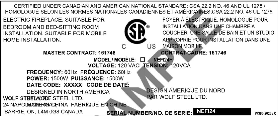
1.4 rating plate information
text_image
CERTIFIED UNDER CANADIAN AND AMERICAN NATIONAL STANDARD: CSA 22.2 NO. 46 AND UL 1278 / HOMOLOGUÉ SELON LES NORMES NATIONALES CANADIENNES ET AMÉRICAINES:CSA 22.2 NO. 46 UL 1278 ELECTRIC FIREPLACE. SUITABLE FOR BEDROOM AND BED-SITTING ROOM INSTALLATION. SUITABLE FOR MOBILE HOME INSTALLATION. FOYER À ÉLECTRIQUE. HOMOLOGUE POUR INSTALLATION DANS UNE CHAMBRE A COUCHER, UNE SALLE DE BAIN ET UN STUDIO. APPROPRIE POUR INSTALLATION DANS UNE MAISON MOBILE. MASTER CONTRACT: 161746 CONTRAT-CADRE: 161746 MODEL / MODELE: □ NEFI24H VOLTAGE: 120 VAC TENSION: 120VCA FREQUENCY: 60Hz FRÉQUENCE: 60Hz POWER: 1500W PUISSANCE: 1500W DATE CODE: XXXXX CODE DE DATE: DESIGNED IN NORTH AMERICA WOLF STEEL/LODF STEEL LTD. 24 NAPOLIN/MANERIKACHINA FABRIQUE EN CHINE BARRIE, ON, L4M 0G8 CANADA DESIGN AMERIQUE DU NORD PAR WOLF STEEL LTD. SERIAL NUMBER/NO. DE SERIE: NEFI24 W385-2026 / CINSTALLER: It is your responsibility to check off the appropriate box on the rating plate according to the model of the appliance.
For rating plate location, see "LABEL LOCATION" section.
This illustration is for reference only. Refer to the rating plate on the log set for accurate information.
NOTE: The rating plate must remain with the appliance at all times. It must not be removed.
NOTE: Do not use the log set during mobile home transportation.
general information
EN
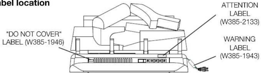
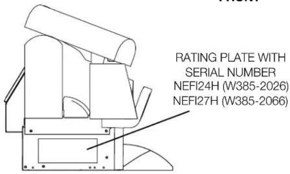
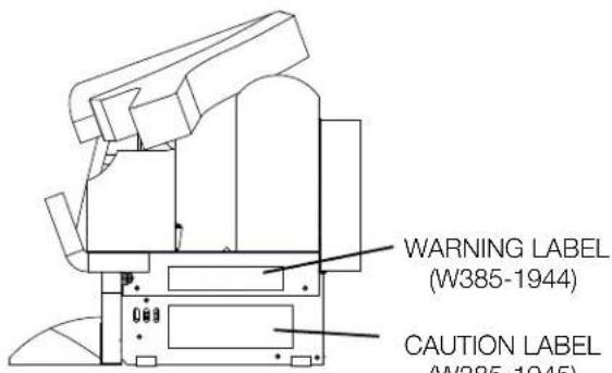
1.5 label location
text_image
label location "DO NOT COVER" LABEL (W385-1946) ATTENTION LABEL (W385-2133) WARNING LABEL (W385-1943)FRONT
text_image
RATING PLATE WITH SERIAL NUMBER NEFI24H (W385-2026) NEFI27H (W385-2066)LEFT SIDE
text_image
WARNING LABEL (W385-1944) CAUTION LABEL (W385-1945)RIGHT SIDE
1.6 locating the log set

WARNING
- Due to high temperatures, this electric appliance should be located out of traffic. Keep combustible materials such as furniture, pillows, bedding, papers, clothes, and curtains at least 36" (91.4cm) from the front of the appliance.
- Never locate this electric appliance where it may fall into a bathtub or other water container.
- Wear safety gloves and safety glasses for protection during installation and maintenance.
- To prevent contact with sagging or loose insulation, the electric appliance must not be installed against vapour barrier or exposed insulation. Localized overheating could occur and a fire could result.
- Do not expose the electric appliance to the elements (i.e. rain, snow, etc.).
Carefully remove the appliance from the box and remove the support brackets. Prior to installing the appliance, remove all packaging material and test to make sure the appliance operates properly by plugging the power supply cord into a conveniently located 120V, 15 Amp minimum grounded outlet.
1.7 grounding log set
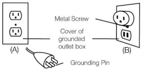
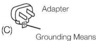
This appliance is for use on 120 volts. The cord has a plug as shown in (A). An adapter as shown in (C) is available for connecting three-blade grounding type plugs to two-slot receptacles, as shown in (B).
The green grounding plug extending from the adapter must be connected to a permanent ground such as a properly grounded outlet box. The adapter should not be used if a three-slot grounded receptacle is available.
To disconnect appliance, turn controls to off, then remove plug from outlet.
Grounding Methods
text_image
(A) Metal Screw Cover of grounded outlet box (B) Grounding PinNot allowed in Canada
text_image
(C) Adapter Grounding Meansnote:
Must be connected to a dedicated 15 amp circuit. The use of an extension cord is NOT permitted.

WARNING
- Risk of fi re! The power cord must not be pinched against a sharp edge. Secure cord to avoid tripping or snagging to reduce the risk of fi re, electric shock, or personal injury. Do not run cord under carpeting. Do not cover cord with throw rugs, runners, or similar items. Arrange cord away from traffic areas and where it will not be tripped over.
- Risk of fi re! To prevent a possible fi re, do not block air intake or exhaust in any manner. Do not use on soft surfaces where openings may become blocked.
- Risk of fi re! Do not blow or place insulation against the appliance.
- This electric appliance is tested and listed for use only with the approved optional accessories. Use of optional accessories not specifically tested for this electric appliance could void the warranty and/or result in a safety hazard.
- If the information in these instructions is not followed exactly, a fire or explosion may result causing property damage, personal injury, or death. Do not store or use gasoline or other flammable vapors in the vicinity of this or any other appliance.
- This appliance is heavy. It is highly recommended that two people install this appliance.
- If your appliance is equipped with a heater, ensure the heater vents cannot, in any way, be covered as it may create a fire hazard.
- Do not run the power cord horizontally, directly below the appliance.
NOTE: Follow all National and local electrical codes.
2.1 log set installation
The log set can be installed in any location. It is suggested to install the log set into an existing fireplace or a wood mantel for aesthetic purposes.
Select a suitable location that is not susceptible to moisture and is away from drapes, furniture and high traffic areas.
2.1.1 installing log set into existing fireplace
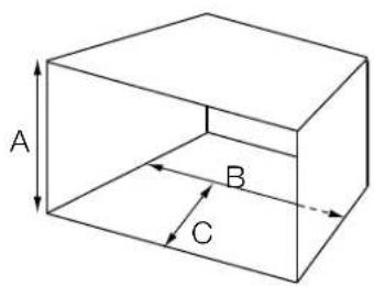
The log set insert must be installed in an opening with the minimum cavity sizes shown below:
MINIMUM FIREPLACE CAVITY SIZE
| HEIGHT WIDTH DEPTHLOG SET A B C | |||
| NEFI24H 15" (381mm) | 24" (610mm) | 14" (356mm) | |
| NEFI27H 16" (406mm) | 27 1/2" (698mm) | 14" (356mm) | |
Do not install the log set into a cavity smaller than that referenced in the table.
text_image
A B CNOTE: Seal all chimney drafts with non-combustible materials to prevent any chimney debris from falling onto the log set. Cap the top of the chimney flue to prevent rain from entering.
Plug the log set into an outlet which has a 15Amp, 120V rating. If it is necessary to hard wire the log set see "HARD WIRING INSTALLATION" section.
WARNING: Due to the high temperatures, do not use existing fireplace doors which close or seal off the log set. If installed behind any fireplace door, allow heat to be exhausted. If using existing screens, the screen must provide adequate airflow in front of the log set.
2.1.2 installing log set into mantel
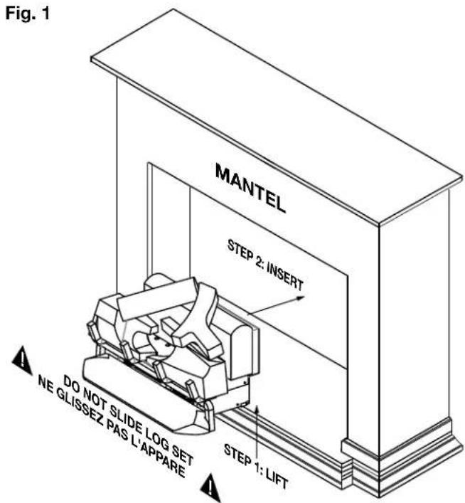
NOTE: To prevent damaging the base of the mantel, carefully lift the log set into the mantel while avoiding contact with the front edge of the mantel base.
A. With two people, lift the log set up and insert into the opening. Do not push or slide the bottom of the log set on the floor base, see Figure 1.
B. Set the log set down and into place, see Figure 2.
text_image
Fig. 1 MANTEL STEP 2: INSERT DO NOT SLIDE LOG SET NE GLISSEZ PAS L'APPARE STEP 1: LIFT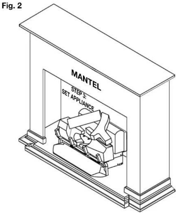
text_image
Fig. 2 MANTEL STEP 3: SET APPLIANCE2.2 hard wiring installation

WARNING
- Turn off the appliance completely and let cool before servicing. Only a qualified service person should service and repair this electric appliance.
HARD WIRING CONNECTION
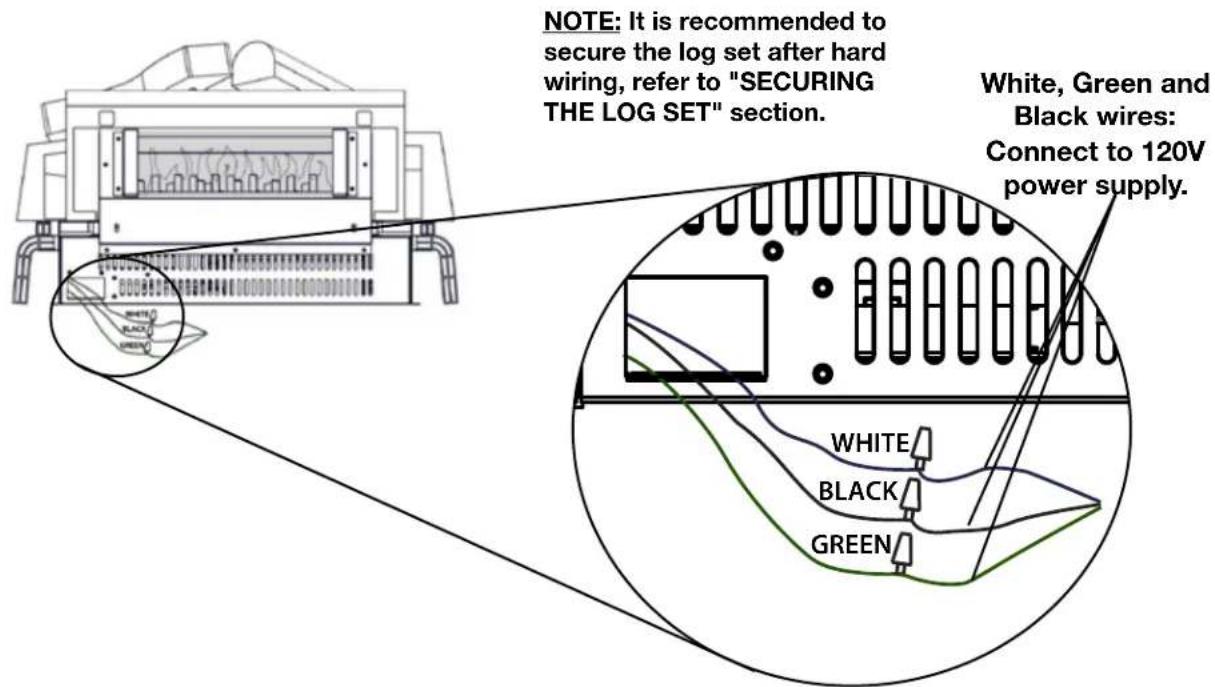
If it is necessary to hard wire, a qualified electrician must remove the cord connection, and wire directly to the household wiring. The wire and power supply breaker must be rated for 120V and a minimum of 15 Amps.
This log set must be electrically connected and grounded in accordance with local codes, if hard wired. In the absence of local codes, use the current CSA C22.1 CANADIAN ELECTRICAL CODE in Canada or the current ANSI/NFPA 70 NATIONAL ELECTRICAL CODE in the United States.
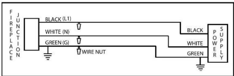
NOTE: There are 3 wires from the fireplace junction; white (neutral), black (power L1) and green (ground) that connect to 120V power supply (breaker panel), see below.
text_image
NOTE: It is recommended to secure the log set after hard wiring, refer to "SECURING THE LOG SET" section. White, Green and Black wires: Connect to 120V power supply. WHITE BLACK GREENA. Remove the securing screw from the electrical cover plate, located on the rear of the log set.
B. Add an electrical box connector and feed the supply wires through the 7/8" (22mm) hole.
C. Separate the black, white and green wires that have the wire nuts on them.
D. Remove the wire nuts and secure the black wire (power L1) to the black (power L1) lead of the power supply. Connect the white wire from the unit to the white (neutral) wire from the power supply. Connect the green wire to the ground wire.
E. Resecure the cover plate.
text_image
FIREPLACE JUNCTION BLACK (L1) WHITE (N) GREEN (G) WIRE NUT BLACK WHITE GREEN P O W E R S U P P L YNOTE: Leave enough wire so that the log set can be removed from the enclosure without disconnecting the power supply.
2.3 securing the log set
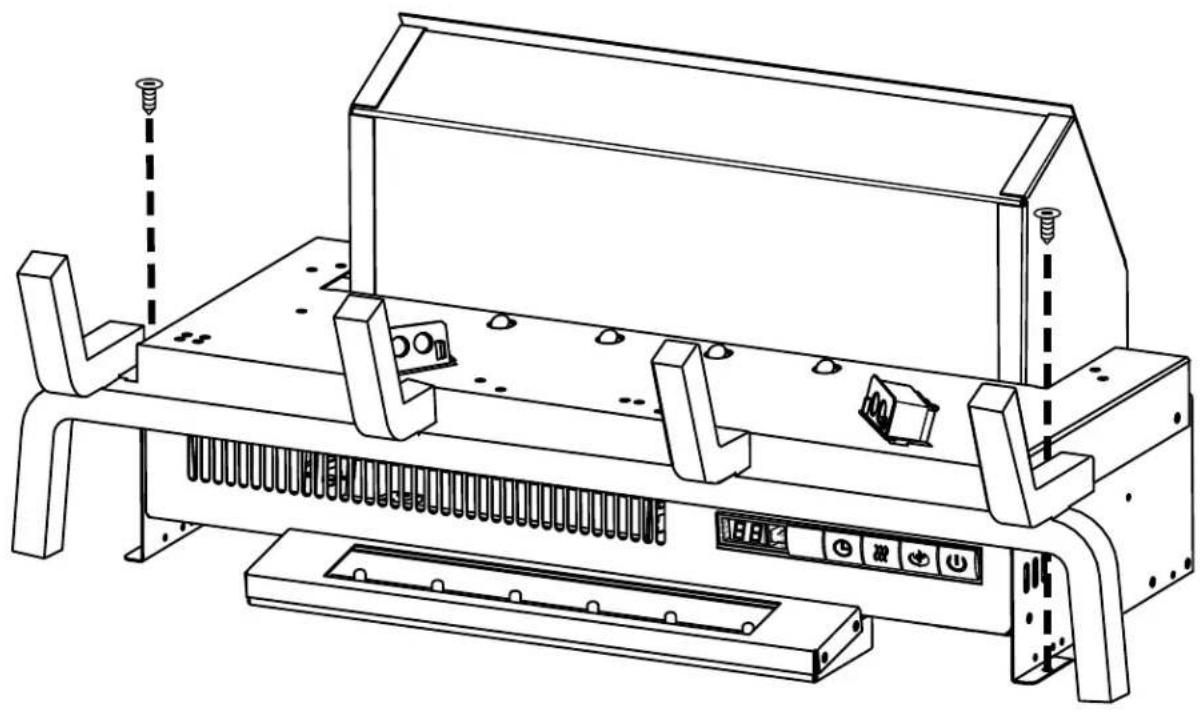
NOTE: It is recommended to secure the log set especially if hard wiring the log set.
A. Place the log set in a position which provides optimum flame performance. NOTE: To achieve flame effect, the log set should be set 1" away from the rear wall.
B. Secure in place using 2 screws (not supplied).
natural_image
Technical line drawing of a mechanical assembly with no visible text or symbols3.0 operating instructions
Once the log set has been plugged into a grounded electrical outlet or hard wired to a dedicated 120V power supply, it is ready to operate.
ATTENTION: Ensure the house circuit breakers for the power supply are turned on. When initially connecting the appliance into a power source the unit will perform an LED check. The unit will flash on and off for 5 seconds.
3.1 operating control panel
The Control Panel is located on the front of the log set.
 |  |  |  |  |
| Power |  | Turns the appliance ON/OFF. |
| Flame & Ember Light Control |  | Controls Flame brightness and the Ember Light.5 Settings: Flame & Ember off (FO), Ember on but Flame off (LL), small Flame & Ember (F1), medium Flame & Ember (F2), brightest Flame and Ember (F3).Default setting is (F3). |
| Heater Control |  | Turns the Heater and Blower ON/OFF.4 Settings: Heater & Blower off (HO), Blower on (BL), low heat (H1), high heat (H2).Default setting is (HO). |
| Timer |  | Timer can be programmed to run appliance for specific lengths of time (30mins. minimum to 6hrs maximum).Default setting is Timer de-select. |
| F^ / C^ Switch |  Hold 5 seconds Hold 5 seconds | To change temperature format, Fahrenheit or Celsius. Press and hold the Flame button® for 5 seconds. Default setting is Fahrenheit. |
| Heater Lock | [5270] Hold 5 seconds | Heater button can be locked or unlocked by holding the Heater button® for 5 seconds. Default setting is heater unlock |
| Temperature Control |  Hold 5 seconds Hold 5 seconds | Press and hold the Timer button® for 5 seconds. This will change the button to Temperature Control, or vice versa. There are 7 temperature settings (61°F, 64°F, 70°F, 75°F, 81°F, 85°F and OFF).Default setting is de-select Temperature Control. |
3.2 operating by remote control

WARNING
- To avoid danger of suffocation, keep the packaging bag away from babies and children. Do not use in cribs, beds, carriages, or play pens. This bag is not a toy. Knot before throwing away.
NOTE: When operating the remote control, it must be directed towards the front center of the log set.
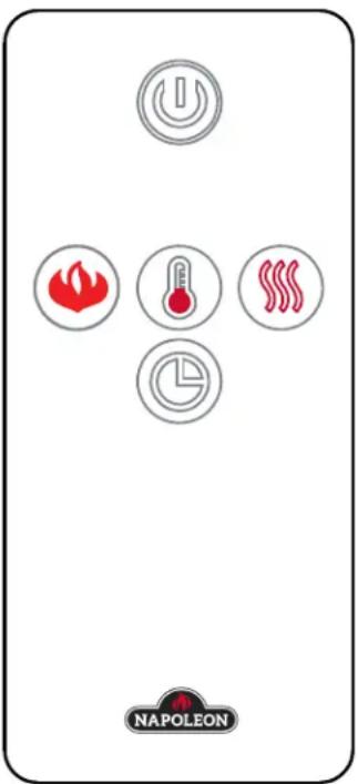
A. The power button can be used to turn the log set on/off. Pressing this button ⚙️ activates the power to the log set. Pressing the power button again will turn off the log set. The ember and log will fade after 4 seconds after turning off the log set.
B. To adjust the flame brightness and ember log light, press the flame button ⚙️. There is one ember log light and three flame brightness levels to cycle through and then an off setting (LL, F1, F2, F3 and then F0). F3 is the brightest flame level, LL is the ember log light only.
C. To control the thermostat function press the thermostat button . There are 7 temperature settings (61°F, 64°F, 70°F, 75°F, 81°F 85°F and off). The default setting will display Fahrenheit. Press the thermostat button to cycle through the settings. Once you have selected the desired temperature the heater will automatically operate until that temperature is reached. When the room temperature is 2 degrees lower than the temperature setting, the heater will turn on.
D. To activate the heater and blower, press the heater button , the blower will turn on. Press the heater button again to set desired low or high heat temperature; press the heater button again to turn off the heater.
E. The timer controls all operating modes of the log set. To activate the timer, press the timer button®, the icon will illuminate and the time will appear on the LED display. To choose the desired time, continue to press the timer button, there are 8 settings (30mins, 1h, 2h, 3h, 4h, 5h, 6h and off). The fireplace will turn off at the setting time.
text_image
NAPLEONF. To turn off the log set, press the power button once on the remote, or press the power button once on the control panel on the unit.
NOTE: This hand held remote control must remain within 6 meters or 19 feet of the log set to be effective.
3.3 remote Battery installation
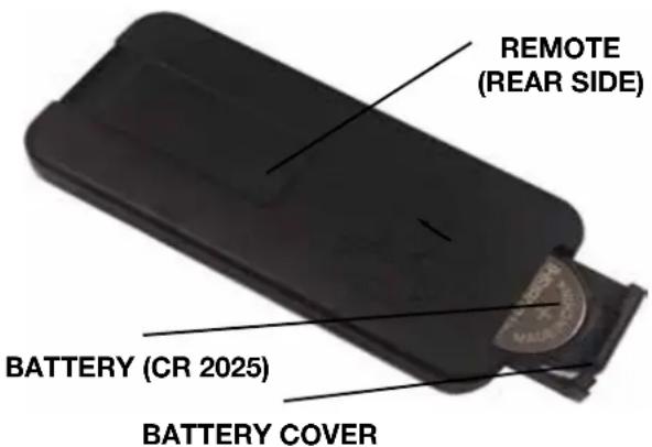
- To replace the existing battery, remote the battery holder.
- To remove the battery holder, turn remote onto front side and press the left side lever towards the center while pulling the battery holder out using the slot provided.
- Replace existing battery, type CR 2025, with a new battery and reinstall the battery holder into the remote by sliding it into position, as shown.
- Battery cover is secure onto the remote control when a "CLICKING" noise is heard.
text_image
REMOTE (REAR SIDE) BATTERY (CR 2025) BATTERY COVER4.0 finishing

WARNING
• Power supply service must be completed prior to finishing to avoid reconstruction.
• Heat vents and air openings cannot be covered in any circumstances.
4.1 NEFI24H log placement
①
text_image
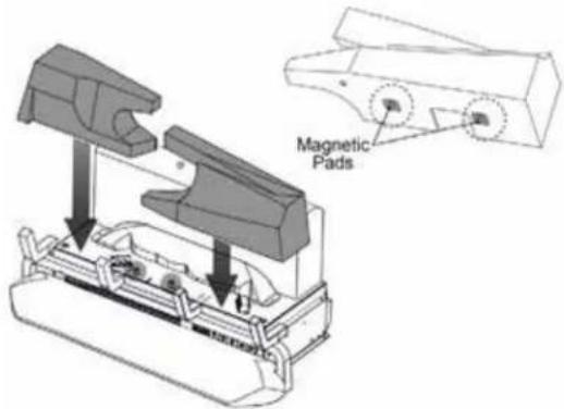
Magnetic PadsPlace the logs shown on the location dimples on the burner platform.
2
text_image
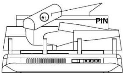
#1 PINPlace the log (#1) onto the pin. Ensure the log is secure onto the pin, as shown.
③
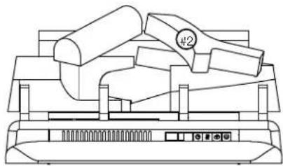
natural_image
Line drawing of a computer monitor with a keyboard and mouse (no text or symbols)Place log (#2) onto the pin. Ensure the log is secure onto the pin, as shown.
4.2 NEFI27H log placement
①
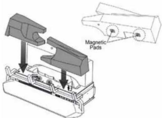
text_image
Magnetic PadsPlace the logs shown on the location dimples on the burner platform.
②
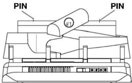
text_image
PIN PIN W1Place log (#1) onto the pin. Ensure the log is secure onto the pin, as shown.
③
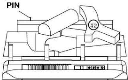
text_image
PIN #2Place log (#2) onto the pin. Ensure the log is secure onto the pin, as shown.
4
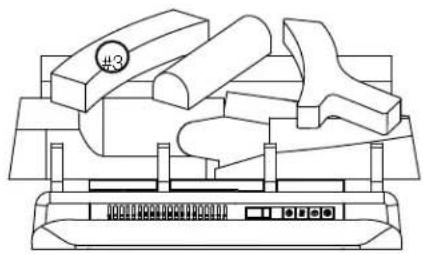
natural_image
Line drawing of a mechanical device with multiple components and a control panel (no text or symbols)Place log (#3) onto the pin. Ensure the log is secure onto the pin, as shown.
4.3 ember bed placement
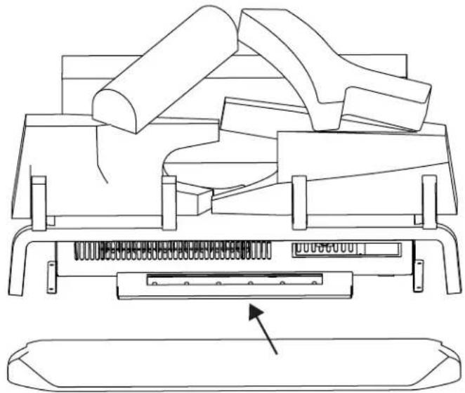
natural_image
Technical line drawing of a mechanical assembly with no visible text or symbolsPlace the ember bed over the LED tray, as shown.
EN
finishing
4.4 charcoal ember placement
A. Place the charcoal ember around the front and sides of the ember bed, as indicated on the diagram below.
NOTE: Do not block air intake opening and outlet with charcoal embers.
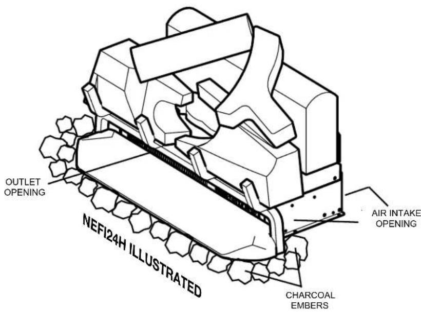
text_image
OUTLET OPENING NEFI24H ILLUSTRATED AIR INTAKE OPENING CHARCOAL EMBERS
WARNING
- Turn off the appliance completely and let cool before servicing. Only a qualified service person should service and repair this electrical appliance.
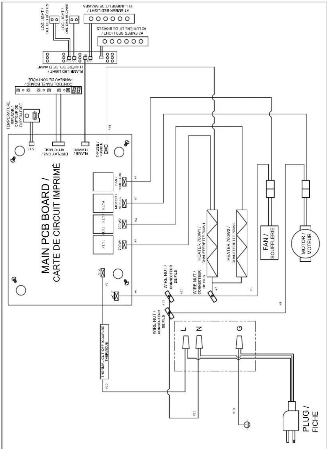
flowchart
graph TD
    A["MAIN PCB BOARD / CARTE DE CIRCUIT IMPRIMÉ"] --> B["FLAME LED LIGHT / LUMINEE OUT DE FRAMFE"]
    A --> C["CONTROL PANEL BOARD / PANENA DE CONTROLE"]
    A --> D["THERMAL CUT-OFF/COUPURE THERMIOUE"]
    A --> E["WIRE NUT / CONNECTEUR DE FILS"]
    A --> F["L/N G"]
    A --> G["PLUG / FICHE"]

    subgraph Power Supply
        H["LOG LIGHT / DEL DES BUCHES"] --> I["1# 8MBER B3D LIGHT / #1 LUMINEE UT DE BRASSES"]
        J["LOG LIGHT / DEL DES BUCHES"] --> K["2# 8MBER B3D LIGHT / #2 LUMINEE UT DE BRASSES"]
        L["TEMPERATURE SENSOR / CAPTEUR DE TEMPERATURE"] --> M["FLAME LED LIGHT / LUMINEE OUT DE FRAMFE"]
        N["DISPLAY CNT / AFFORCE"] --> O["NTC"]
    end

    subgraph Power Supply
        P["FAN / SOUFFLERIE"] --> Q["HEATER 700W1 / CHAUFFERETTE 700W1"]
        R["MOTOR / MOTEUR"] --> S["700W2"]
        T["RUY"] --> U["700W1"]
        V["RUY"] --> W["700W1"]
        X["RUY"] --> Y["700W1"]
        Z["RUY"] --> AA["700W1"]
        AB["RUY"] --> AC["700W1"]
        AD["RUY"] --> AE["700W1"]
        AF["RUY"] --> AG["700W1"]
        AH["RUY"] --> AI["700W1"]
        AJ["RUY"] --> AK["700W1"]
        AL["RUY"] --> AM["700W1"]
        AN["RUY"] --> AO["700W1"]
        AP["RUY"] --> AQ["700W1"]
        AR["RUY"] --> AS["700W1"]
        AT["RUY"] --> AU["700W1"]
        AV["RUY"] --> AW["700W1"]
        AX["RUY"] --> AY["700W1"]
        AZ["RUY"] --> BA["700W1"]
        BB["RUY"] --> BC["700W1"]
        BD["RUY"] --> BE["700W1"]
        BF["RUY"] --> BG["700W1"]
        BH["RUY"] --> BI["700W1"]
        BJ["RUY"] --> BK["700W1"]
        BL["RUY"] --> BLA["700W1"]
        BM["RUY"] --> BN["700W1"]
        BO["RUY"] --> BP["700W1"]
        BQ["RUY"] --> BR["700W1"]
        BS["RUY"] --> BT["700W1"]
        BU["RUY"] --> BV["700W1"]
        BW["RUY"] --> BX["700W1"]
        BY["RUY"] --> BYA["700W1"]
        BZ["RUY"] --> BZA["700W1"]
        CA["RUY"] --> CAA["700W1"]
        CB["RUY"] --> CBA["700W1"]
        CC["RUY"] --> CE["700W1"]
        CF["RUY"] --> CFA["700W1"]
        GD["RUY"] --> GDAB["700W1"]
        BE["BATUR DE FILS"] --> BF
    end

    %% Note: The diagram shows connections between components and wires, with labels indicating their respective functions and identifiers.

WARNING
- Failure to position the parts in accordance with this manual or failure to use only parts specifically approved with this appliance may result in property damage or personal injury.
Contact your dealer for questions concerning prices and policies on replacement parts. Normally, all parts can be ordered through your Authorized dealer / distributor.
For warranty replacement parts, a photocopy of the original invoice will be required to honour the claim.
When ordering replacement parts always give the following information:
• Model & Serial Number of appliance
• Installation date of appliance
- Part number
• Description of part
- Finish
Parts, part numbers, and availability are subject to change without notice.
Parts identified as stocked will be delivered within 2 to 5 business days for most delivery destinations.
Parts not identified as stocked will be delivered within a 2 to 4 week period, for most cases.
Parts identified as 'SO' are special order and can take up to 90 days for delivery.
For after sales service, please call 1-866-820-8686
6.1 NEFI24H overview
NOTE: Care must be taken when removing and disposing of any broken glass or damaged components. Be sure to vacuum up any broken glass from inside the appliance before operation.
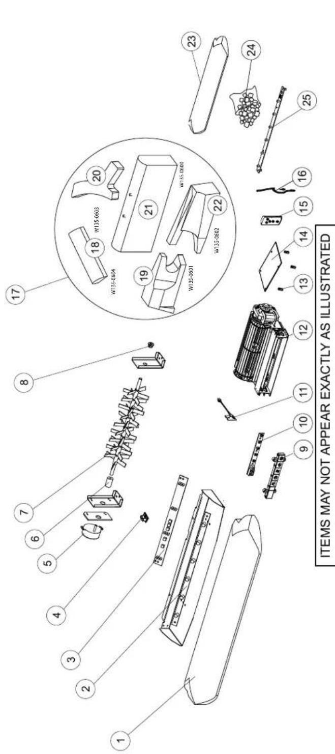
text_image
ITEMS MAY NOT APPEAR EXACTLY AS ILLUSTRATED| DESCRIPTIONPART NO.REF. | ||
| 14 | G190-0005 | MAIN PCB BOARD |
| 15 | G660-0004 | REMOTE CONTROL TRANSMITTER |
| 16 | G750-0032-SER | WIRE ASSEMBLY |
| 17 | W010-3833-SER | LOG SERVICE PART KIT, NEFI24H |
| 18 | W135-0604 | TOP LEFT LOG |
| 19 | W135-0601 | FRONT LEFT LOG |
| 20 | W135-0603 | TOP RIGHT LOG |
| 21 | W135-0600 | REAR LOG |
| 22 | W135-0602 | FRONT RIGHT LOG |
| 23 | W135-0610 | EMBER BED, REAR |
| 24 | W550-0013 | CHARCOAL, EMBER |
| 25 | G405-0011 | REAR EMBER LED |
| DESCRIPTIONPART NO.REF. | ||
| 1 W135-0605 | EMBER BED, FRONT | |
| 2 | W405-0023 | EMBER BED LED |
| 3 | W405-0025 | FLAME LED, NEFI24H |
| 4 | G405-0012 | LOG LED |
| 5 | W435-0059 | SYNCHRONOUS MOTOR |
| 6 | W005-0019 | ADAPTOR |
| 7 | W010-3617 | REFLECTOR, NEFI24H |
| 8 | W105-0020 | BUSHING |
| 9 | G010-0081 | CONTROL PANEL, NEFI24H |
| 10 | G190-0006 | CONTROL PANEL BOARD |
| 11 | G190-0004 | TEMPERATURE SENSOR |
| 12 | G010-0079 | BLOWER & HEATER ASSEMBLY |
| 13 | G615-0002 | SPACER, 4PCS |
6.2 NEFI27H overview
NOTE: Care must be taken when removing and disposing of any broken glass or damaged components. Be sure to vacuum up any broken glass from inside the appliance before operation.
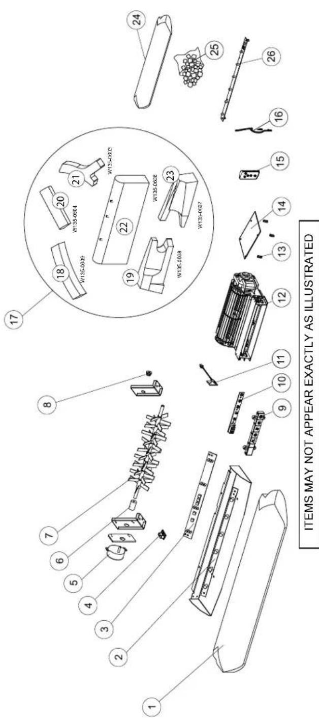
text_image
ITEMS MAY NOT APPEAR EXACTLY AS ILLUSTRATED| REF. | PART NO. | DESCRIPTION |
| 14 | G190-0005 | MAIN PCB BOARD |
| 15 | G660-0004 | REMOTE CONTROL TRANSMITTER |
| 16 | G750-0032-SER | WIRE ASSEMBLY NEFI24H/NEFI27H |
| 17 | W010-3834-SER | LOG SERVICE PART KIT, NEFI27H |
| 18 | W135-0609 | TOP LEFT LOG |
| 19 | W135-0608 | FRONT LEFT LOG |
| 20 | W135-0604 | TOP CENTRE LOG |
| 21 | W135-0603 | TOP RIGHT LOG |
| 22 | W135-0606 | REAR LOG |
| 23 | W135-0607 | FRONT RIGHT LOG |
| 24 | W135-0610 | EMBER BED, REAR |
| 25 | G020-0014 | CHARCOAL, EMBER |
| 26 | G405-0011 | REAR EMBER LED |
| REF. | PART NO. | DESCRIPTION |
| 1 | W135-0605 | EMBER BED, FRONT |
| 2 | W405-0023 | EMBER BED LED |
| 3 | W405-0025 | FLAME LED, NEFI24H |
| 4 | G405-0012 | LOG LED |
| 5 | W435-0059 | SYNCHRONOUS MOTOR |
| 6 | W005-0019 | ADAPTOR |
| 7 | W010-3617 | REFLECTOR, NEFI27H |
| 8 | W105-0020 | BUSHING |
| 9 | G010-0081 | CONTROL PANEL, NEFI27H |
| 10 | G190-0006 | CONTROL PANEL BOARD |
| 11 | G190-0004 | TEMPERATURE SENSOR |
| 12 | G010-0079 | BLOWER & HEATER ASSEMBLY |
| 13 | W615-0135 | SPACER, 4 PCS |
WARNING
- Turn off the appliance completely and let cool before servicing. Only a qualified service person should service and repair this electric appliance.
symptom problem solution
| Appliance will not come on when power button/ switch is put into the “on” position. | Appliance is not plugged into an electrical outlet. | Check plug, and plug in the appliance if necessary. |
| Hard-wire connections are not correct (if applicable). | See “hard-wiring installation” section. | |
| Appliance has overheated and safety thermal switch has tripped. | Unlug power or turn off the circuit breaker, allow appliance to cool for 15 minutes, then plug in the appliance or turn the breaker on. | |
| Main PCB board issue. Inspect the circuit board and replace, if necessary. | ||
| Appliance turns off and will not turn on. | House circuit breaker has tripped. | Reset house circuit breaker. |
| Appliance’s fuse has blown. Replace the fuse. | ||
| Appliance has overheated and safety thermal switch has tripped. | Unplug power or turn off the circuit breaker, allow appliance to cool for 15 minutes to reset the thermal switch, then plug in the appliance or turn the breaker on. | |
| Appliance has returned to default settings. | Power failure. Re-program appliance to original settings (not applicable with all appliances). | |
| Remote control does not work. | Low/dead batteries. Replace batteries in remote control. | |
| Remote receiver malfunction. Ensure remote receiver is not blocked. Replace control panel. | ||
| No warm air coming out of the appliance. | Heater setting not selected. See “operation” section. | |
| Heater has been locked out. See “operation” section. | ||
| Room temperature is higher than appliance setting (if set to room temperature). | Reset temperature setting. | |
| Appliance has overheated and safety thermal switch has tripped. | Unplug power or turn off the circuit breaker. Allow for appliance to cool for 15 minutes. | |
| Hard-wire connections are not correct (if applicable). | See “hard-wiring installation” section. | |
| Heater issue. Inspect the blower and heater and replace, if necessary. | ||
| Heater shuts off automatically. | Room is too warm. The heater has a built-in thermostat so it will shut off automatically once the pre-set temperature is reached. It will also turn on automatically if the room temperature drops below the pre-set temperature. | |
| Dim or no flame. | Flame brightness not selected. | See “operation” section. |
| Flame LEDs issue. | Inspect the LED and replace, if necessary. | |
| Main PCB board issue. Inspect the main PCB board and replace, if necessary. | ||
| Flame does not move. | Motor is stalled/malfunctioning. | Cycle on/off. If problem persists, consult dealer. |
| Ember bed is not glowing or dimming. | Brightness not selected. | See “operation” section. |
| Ember LED issue. | Inspect the ember bed LEDs and replace, if necessary. | |
| Main PCB board issue. Inspect the main PCB board and replace, if necessary. | ||
| LED flashing “OH”. | Appliance has overheated and safety thermal switch has tripped. | Unplug power or turn off the circuit breaker. Allow appliance to cool for 15 minutes, then plug in the appliance or turn the breaker on. If problem persists, consults your dealer. |
Napoleon electric appliances are manufactured under the strict Standard of the world recognized ISO 9001 : 2015 Quality Management System.
Napoleon products are designed with superior components and materials and assembled by trained craftsmen who take great pride in their work. Once assembled, the complete appliance is thoroughly inspected by a qualified and authorized installer, service agency, or supplier before packing to ensure that you, the customer, receive the quality product that you expect from Napoleon.
Napoleon Electric Appliance Standard Warranty
Electrical components and wearable parts are covered and Napoleon will provide replacement parts free of charge during the first year of standard warranty. This covers: fan/heaters, motors, switches, nylon bearing components, remote controls, and LED lights.*
Light bulbs and fuses are NOT covered by the warranty.
Any labour related to warranty repair is not covered.
* Construction of models vary. Warranty applies only to components included with your specific appliance.
Conditions and Limitations
Napoleon warrants its products against manufacturing defects to the original purchaser only. Registering your warranty is not necessary. Simply provide your proof of purchase along with the model and serial number to make a warranty claim. Provided that the purchase was made through an authorized Napoleon dealer, your appliance is subject to the following conditions and limitations:
Warranty coverage begins on the date of original installation.
This factory warranty is non-transferable and may not be extended whatsoever by any of our representatives.
Installation must be done in accordance with the installation instructions included with the product and all local and national building and fire codes.
This standard warranty does not cover damages caused by misuse, lack of maintenance, accident, alterations, abuse, or neglect and parts installed from other manufacturers will nullify this warranty.
This standard warranty further does not cover any scratches, dents, corrosion, or discolouring caused by excessive heat, abrasive and chemical cleaners, nor chipping on porcelain enamel parts, mechanical breakage of PHAZER™ logs.
In the first year only, this warranty extends to the repair or replacement of warranted parts which are defective in material or workmanship, provided that the product has been operated in accordance with the operation instructions and under normal conditions.
Napoleon will not be responsible for installation, labour, or any other expenses related to the reinstallation of a warranted part, and such expenses are not covered by this warranty. Notwithstanding any provisions contained in the Standard Warranty, Napoleon responsibility under this warranty is defined as above, and it shall not in any event extend to any incidental, consequential, or indirect damages.
This warranty defines the obligations and liability of Napoleon with respect to the Napoleon electric appliance and any other warranties expressed or implied with respect to this product; its components or accessories are excluded.
Napoleon neither assumes, nor authorizes any third party to assume, on its behalf, any other liabilities with respect to the sale of this product.
Any damages to appliance, brass trim or other component due to water, weather damage, long periods of dampness, condensation, damaging chemicals, or cleaners will not be the responsibility of Napoleon.
Napoleon reserves the right to have its representative inspect any product or part thereof prior to honouring any warranty claim.
All parts replaced under the Standard Warranty Policy are subject to a single claim.
All parts replaced under the warranty will be covered for a period of 90 days from the date of their installation.
The manufacturer may require that defective parts or products be returned or that digital pictures be provided to support the claim. Returned products are to be shipped prepaid to the manufacturer for investigation. If a product is found to be defective, the manufacturer will repair or replace such defect.
Before shipping your appliance or defective components, your dealer must obtain an authorization number. Any merchandise shipped without authorization will be refused and returned to sender.
Shipping costs are not covered under this warranty.
Additional service fees may apply if you are seeking warranty service from a dealer.
All specifications and designed are subject to change without prior notice due to on-going product improvements. Napoleon is a registered trademark of Wolf Steel Ltd.
| Appliance Service HistoryThis appliance must be serviced annually depending on usage. | |||||
| Date Dealer Name Service Technician Name Service Performed Special Concerns | |||||
NAPOLEON CELEBRATING OVER 40 YEARS OF HOME COMFORT PRODUCTS
natural_image
Interior view of a modern living room featuring a dark fire extinguisher on a white wall, with shelves and a sofa in the foreground (no visible text or symbols)
natural_image
Exterior view of a modern outdoor grill with a large grater, set against residential houses and stone walls (no signage or text visible)
natural_image
Interior view of a modern kitchen with a washing machine and tiled flooring (no visible text or symbols)NAPOLEON
24 Napoleon Road, Barrie, Ontario, Canada L4M 0G8
214 Bayview Drive, Barrie, Ontario, Canada L4N 4Y8
103 Miller Drive, Crittenden, Kentucky, USA 41030
De Riemsdijk 22, 4004 LC Tiel, The Netherlands
Phone: 1-866-820-8686
napoleon.com

text_image
NAPOLEONMANUEL D'INSTALLATION ET D'OPÉRATION
natural_image
Line drawing of a mechanical assembly with no visible text or symbolsCONSIGNES DE SÉCURITÉ
! AVERTISSEMENT
RISQUE D'INCENDIE OU D'EXPLOSION
1.4 plaque d'homologation
CERTIFIED UNDER CANADIAN AND AMERICAN NATIONAL STANDARD: CSA 22.2 NO. 46 AND UL 1278 / HOMOLOGUÉ SELON LES NORMES NATIONALES CANADIENNES ET AMÉRICAINES:CSA 22.2 NO. 46 UL 1278
ELECTRIC FIREPLACE. SUITABLE FOR BEDROOM AND BED-SITTING ROOM INSTALLATION. SUITABLE FOR MOBILE HOME INSTALLATION.

C
FOYER À ÉLECTRIQUE. HOMOLOGUE POUR INSTALLATION DANS UNE CHAMBRE A COUCHER, UNE SALLE DE BAIN ET UN STUDIO. APPROPRIE POUR INSTALLATION DANS UNE MAISON MOBILE.
CONTRAT-CADRE: 161746
MASTER CONTRACT: 161746
MODEL / MODÈLE:
NEFI24H
VOLTAGE: 120 VAC
TENSION: 120VCA
FREQUENCY: 60Hz
FRÉQUENCE: 60Hz
POWER: 1500W
PUISSANCE: 1500W
DATE CODE: XXXXX
CODE DE DATE:
DESIGNED IN NORTH AMERICA
DESIGN AMERIQUE DU NORD
BY WOLF STEEL LTD.
PAR WOLF STEEL LTD.
MADE IN CHINA
FABRIQUE EN CHINE
SERIAL NUMBER/NO. DE SERIE:
NEFI24
W385-2026 / C
text_image
N E CÔTÉ DROITAVERTISSEMENT
L'ÉTIQUETTE (W385-1944)
AVERTISSEMENT
L'ÉTIQUETTE (W385-1945)
natural_image
Technical line drawing of a mechanical assembly with no visible text or symbolstext_image
Magnetic Padsnatural_image
Line drawing of a mechanical assembly with no visible text or symbolstext_image
Magnetic Padsnatural_image
Technical line drawing of a mechanical assembly with no visible text or symbolsnatural_image
Technical line drawing of a mechanical assembly with no visible text or symbolstext_image
CES ARTICLES PEUT DIFFÉRER DE CELLE ILLUSTRÉ| RÉF. | NO. DE PIÈCE | DESCRIPTION |
| 14 | G190-0005 | CARTE DE CIRCUIT IMPRIMÉ |
| 15 | G660-0004 | TÉLÉCOMMANDE |
| 16 | G750-0032-SER | ENSEMBLE DE FILS |
| 17 | W010-3833-SER | KIT DE BÛCHES, NEFI24H |
| 18 | W135-0604 | BÛCHE SUPÉRIEURE GAUCHE |
| 19 | W135-0601 | BÛCHE AVANT GAUCHE |
| 20 | W135-0603 | BÛCHE SUPÉRIEURE DROITE |
| 21 | W135-0600 | BÛCHE ARRIÈRE |
| 22 | W135-0602 | BÛCHE AVANT DROIT |
| 23 | W135-0610 | LIT DE BRAISES, ARRIÈRE |
| 24 | W550-0013 | BRAISES DE CHARBON |
| 25 | G405-0011 | DEL DE PLATEAU |
| RÉF. | NO. DE PIÈCE | DESCRIPTION |
| 1 | W135-0605 | LIT DE BRAISES, AVANT |
| 2 | W405-0023 | DEL LIT DE BRAISES |
| 3 | W405-0025 | DEL DE FLAMME, NEFI24H |
| 4 | G405-0012 | DEL DE BÜCHES |
| 5 | W435-0059 | MOTEUR SYNCHRONE |
| 6 | W005-0019 | ADAPTEUR |
| 7 | W010-3617 | REFLECTEUR, NEFI24H |
| 8 | W105-0020 | BAGUE |
| 9 | G010-0081 | PANNEAU DE CONTRÔLE, NEFI24H |
| 10 | G190-0006 | BORD PANNEAU DE CONTRÔLE |
| 11 | G190-0004 | CAPTEUR DE TEMPÉRATURE |
| 12 | G010-0079 | ASSEMBLAGE DE CHAUFFERETTE SOUFFLERIE |
| 13 | G615-0002 | ESPACEUR , PIÈCES 4 |
table des matières
text_image
CES ARTICLES PEUT DIFFÉRER DE CELLE ILLUSTRÉ| RÉF. | NO. DE PIÈCE | DESCRIPTION |
| 14 | G190-0005 | CARTE DE CIRCUIT IMPRIMÉ |
| 15 | G660-0004 | TÉLÉCOMMANDE MANUELLE |
| 16 | G750-0032-SER | ENSEMBLE DE FILS, NEFI24H/NEFI27H |
| 17 | W010-3834-SER | KIT DE BÜCHES, NEFI27H |
| 18 | W135-0609 | BÜCHE DE SUPÉRIEURE GAUCHE |
| 19 | W135-0608 | BÜCHE DE AVANT GAUCHE |
| 20 | W135-0604 | BÜCHE DE SUPÉRIEURE CENTRALE |
| 21 | W135-0603 | BÜCHE DE SUPÉRIEURE DROITE |
| 22 | W135-0606 | BÜCHE DE ARRIÈRE |
| 23 | W135-0607 | BÜCHE DE AVANT DROIT |
| 24 | W135-0610 | LIT DE BRAISES ARRIÈRE |
| 25 | G020-0014 | BRAISES DE CHARBON |
| 26 | G405-0011 | DEL DU PLATEAU |
| RÉF. | NO. DE PIÈCE | DESCRIPTION |
| 1 | W135-0605 | LIT DE BRAISES, AVANT |
| 2 | W405-0023 | DE LIT DE BRAISES |
| 3 | W405-0025 | DE DE FLAMME, NEFI24H |
| 4 | G405-0012 | DEL DE BÜCHES |
| 5 | W435-0059 | MOTEUR SYNCHRONE |
| 6 | W005-0019 | ADAPTEUR |
| 7 | W010-3617 | REFLECTEUR, NEFI27H |
| 8 | W105-0020 | BAGUE |
| 9 | G010-0081 | PANNEAU DE CONTRÔLE, NEFI24H |
| 10 | G190-0006 | BORD PANNEAU DE CONTRÔLE |
| 11 | G190-0004 | CAPTEUR DE TEMPÉRATURE |
| 12 | G010-0079 | ASSEMBLAGE DE CHAUFFERETTE SOUFFLERIE |
| 13 | W615-0135 | ESPACEUR, 4 PIÉCES 4 |

AVERTISSEMENT
FR
natural_image
Interior view of a modern living room featuring a dark gas stove with visible flames and a wooden backrest (no text or symbols)
natural_image
Exterior view of a modern outdoor grill with a large grater, surrounded by residential houses and stone walls (no signage or text visible)
natural_image
Interior view of a modern kitchen with a washing machine and tiled flooring (no visible text or symbols)
24 Napoleon Road, Barrie, Ontario, Canada L4M 0G8
214 Bayview Drive, Barrie, Ontario, Canada L4N 4Y8
103 Miller Drive, Crittenden, Kentucky, USA 41030