
GL30NE - Fireplace Napoleon - Free user manual and instructions
Find the device manual for free GL30NE Napoleon in PDF.


| Product type | Fireplace |
| Brand | Napoleon |
| Model | GL30NE |
| Dimensions (H x W x D) | 1000 x 800 x 500 mm |
| Weight | 80 kg |
| Fuel | Natural gas |
| Heating power | Up to 10 kW |
| Main functions | Heating, decorative flame, remote control |
| Flue connection | DN 150 mm |
| Material | Steel, tempered glass |
| Color | Black |
| Glass area | Large panoramic glass |
| Maintenance | Regular cleaning of the burner and glass |
| Safety | Automatic shut-off, overheat protection, child safety |
| Spare parts | Glass, burner, remote control, thermocouple |
| Repairability | Parts available from the manufacturer |
| General information | Indoor use, professional installation required |
Frequently Asked Questions - GL30NE Napoleon
User questions about GL30NE Napoleon
0 question about this device. Answer the ones you know or ask your own.
Ask a new question about this device
Download the instructions for your Fireplace in PDF format for free! Find your manual GL30NE - Napoleon and take your electronic device back in hand. On this page are published all the documents necessary for the use of your device. GL30NE by Napoleon.
USER MANUAL GL30NE Napoleon
INSTALLER: LEAVE THIS MANUAL WITH THE APPLIANCE.
CONSUMER: RETAIN THIS MANUAL FOR FUTURE REFERENCE.
NEVER LEAVE CHILDREN OR OTHER AT RISK INDIVIDUALS ALONE WITH THE APPLIANCE.

QUALITY FIREPLACES
INSTALLATION AND OPERATING INSTRUCTIONS
CERTIFIED UNDER: ANSI Z21.60 / CSA 2.26 DECORATIVE GAS APPLIANCES FOR INSTALLATION IN SOLID-FUEL BURNING APPLIANCES
GL18NE, GL24NE,
GL30NE
NATURAL GAS
GL18PE, GL24PE,
GL30PE
PROPANE
CERTIFIED FOR CANADA AND UNITED STATES USING ANSI/CSA METHODS.
SAFETY INFORMATION
! WARNING
If the information in these instructions are not followed exactly, a fi re or explosion may result causing property damage, personal injury or loss of life.
- Do not store or use gasoline or other fl ammable vapors and liquids in the vicinity of this or any other appliance.
- WHAT TO DO IF YOU SMELL GAS:
- Do not try to light any appliance.
- Do not touch any electrical switch; do not use any phone in your building.
- Immediately call your gas supplier from a neighbour's phone. Follow the gas supplier's instructions.
- If you cannot reach your gas supplier, call the fi re department.
- Installation and service must be performed by a qualified installer, service agency or the supplier.
This appliance may be installed in an aftermarket, permanently located, manufactured home (USA only) or mobile home, where not prohibited by local codes.
This appliance is only for use with the type of gas indicated on the rating plate. This appliance is not convertible for use with other gases, unless a certifi ed kit is used.


Quality System Certified To

9001-2008



Wolf Steel Ltd., 24 Napoleon Rd., Barrie, ON, L4M 0G8 Canada /
103 Miller Drive, Crittenden, Kentucky, USA, 41030
Phone (705)721-1212 • Fax (705)722-6031 • www.napoleonfireplaces.com • ask@napoleonproducts.com
\$10.00
.1.37
TABLE OF CONTENTS
| 1.0 | INSTALLATION | OVERVIEW | 2 | ||||
| 2.0 | INTRODUCTION | 3 | |||||
| 2.1 | GENERAL | INSTRUCTIONS | 4 | ||||
| 2.2 | GENERAL | INFORMATION | 5 | ||||
| 2.3 | MINIMUM | APPLIANCE | SIZE | 5 | |||
| 2.4 | RATING | PLATE | 5 | ||||
| 3.0 | INSTALLATION | 6 | |||||
| 3.1 | GAS | PIPING | 6 | ||||
| 3.2 | DAMPER STOP INSTALLATION | 7 | |||||
| 4.0 | FINISHING | 8 | |||||
| 4.1 | ANDIRON | AND | GRATE | ASSEMBLY | 8 | ||
| 4.2 | BATTERY | INSTALLATION | 8 | ||||
| 4.3 | LOG | PLACEMENT | 9 | ||||
| 4.4 | MEDIA | 10 | |||||
| 4.5 | LOGO | PLACEMENT | 10 | ||||
| 4.6 | OPTIONAL ROCK PLACEMENT | 11 | |||||
| 4.7 | OPTIONAL REMOTE INSTALLATION (NOT SUPPLIED) | 11 | |||||
| 5.0 | WIRING | DIAGRAM | 12 | ||||
| 6.0 | OPERATION | 13 | |||||
| 6.1 | OPERATING AND LIGHTING INSTRUCTIONS | 13 | |||||
| 7.0 | ADJUSTMENTS | 14 | |||||
| 7.1 | PILOT | BURNER | ADJUSTMENT | 14 | |||
| 7.2 | VENTURI | ADJUSTMENT | 14 | ||||
| 7.3 | FLAME | CHARACTERISTICS | 15 | ||||
| 8.0 | MAINTENANCE | 15 | |||||
| 9.0 | REPLACEMENTS | 16 | |||||
| 10.0 | TROUBLE SHOOTING | 18 | |||||
| 11.0 | WARRANTY | 20 | |||||
| 12.0 | SERVICE HISTORY | 21 | |||||
NOTE: Changes, other than editorial, are denoted by a vertical line in the margin.
1.0 INSTALLATION OVERVIEW
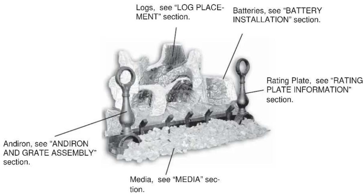
2.0 INTRODUCTION
! WARNING
- THIS APPLIANCE IS HOT WHEN OPERATED AND CAN CAUSE SEVERE BURNS IF CONTACTED. - ANY CHANGES OR ALTERATIONS TO THIS APPLIANCE OR IT'S CONTROLS CAN BE DANGEROUS AND IS PROHIBITED.
- Do not operate appliance before reading and understanding operating instructions. Failure to operate appliance according to operating instructions could cause fire or injury.
- Risk of fire or asphyxiation do not operate appliance with fixed glass removed.
- Do not connect 110 volts to the control valve.
- Risk of burns. The appliance should be turned off and cooled before servicing.
- Do not install damaged, incomplete or substitute components.
- Risk of cuts and abrasions. Wear protective gloves and safety glasses during installation. Sheet metal edges may be sharp.
- Do not burn wood or other materials in this appliance.
- Children and adults should be alerted to the hazards of high surface temperature and should stay away to avoid burns or clothing ignition. Toddlers, young children and others may be susceptible to accidental contact burns. A physical barrier is recommended if there are at risk individuals in the house. To restrict access to an appliance or stove, install an adjustable safety gate to keep toddlers, young children and other at risk individuals out of the room and away from hot surfaces.
• Clothing or other flammable material should not be placed on or near the appliance.
- Due to high temperatures, the appliance should be located out of traffic and away from furniture and draperies.
- Ensure you have incorporated adequate safety measure to protect infants/toddlers from touching hot surfaces.
• Even after the appliance is out, the glass and/or screen will remain hot for an extended period of time.
- Check with your local hearth specialty dealer for safety screens and hearth guards to protect children from hot surfaces. These screens and guards must be fastened to the floor.
- Any safety screen or guard removed for servicing must be replaced prior to operating the appliance.
• This appliance is a vented gas-fired appliance. Do not burn wood or other materials in this appliance.
- It is imperative that the control compartments, burners and circulating blower and its passageway in the appliance and venting system are kept clean. The appliance and its venting system should be inspected before use and at least annually by a qualified service person. More frequent cleaning may be required due to excessive lint from carpeting, bedding material, etc. The appliance area must be kept clear and free from combustible materials, gasoline and other flammable vapors and liquids.
- Under no circumstances should this appliance be modified.
- This appliance must not be connected to a chimney flue pipe serving a separate solid fuel burning appliance.
- Do not use this appliance if any part has been under water. Immediately call a qualified service technician to inspect the appliance and to replace any part of the control system and any gas control which has been under water.
- Do not operate the appliance with the glass door removed, cracked or broken. Replacement of the glass should be done by a licensed or qualified service person.
- Do not strike or slam shut the appliance glass door.
• Only doors / optional fronts certified with the unit are to be installed on the appliance.
- Keep the packaging material out of reach of children and dispose of the material in a safe manner. As with all plastic bags, these are not toys and should be kept away from children and infants.
- As with any combustion appliance, we recommend having your appliance regularly inspected and serviced as well as having a Carbon Monoxide Detector installed in the same area to defend you and your family against Carbon Monoxide.
- Ensure clearances to combustibles are maintained when building a mantel or shelves above the appliance. Elevated temperatures on the wall or in the air above the appliance can cause melting, discolouration or damage to decorations, a T.V. or other electronic components.
3.16B
2.1 GENERAL INSTRUCTIONS
| WARNING |
| ALWAYS LIGHT THE PILOT WHETHER FOR THE FIRST TIME OR IF THE GAS SUPPLY HAS RUN OUT, WITH THE GLASS DOOR OPENED OR REMOVED. |
| PROVIDE ADEQUATE CLEARANCE FOR SERVICING AND OPERATING THE APPLIANCE. |
| PROVIDE ADEQUATE VENTILATION. |
| NEVER OBSTRUCT THE FRONT OPENING OF THE APPLIANCE. |
| OBJECTS PLACED IN FRONT OF THE APPLIANCE MUST BE KEPT A MINIMUM OF 48” FROM THE FRONT FACE OF THE UNIT. |
| SURFACES AROUND AND ESPECIALLY ABOVE THE APPLIANCE CAN BECOME HOT. AVOID CONTACT WHEN THE APPLIANCE IS OPERATING. |
| FIRE RISK. EXPLOSION HAZARD. |
| HIGH PRESSURE WILL DAMAGE VALVE. DISCONNECT GAS SUPPLY PIPING BEFORE PRESSURE TESTING GAS LINE AT TEST PRESSURES ABOVE 1/2 PSIG. CLOSE THE MANUAL SHUT-OFF VALVE BEFORE PRESSURE TESTING GAS LINE AT TEST PRESSURES EQUAL TO OR LESS THAN 1/2 PSIG. |
| USE ONLY WOLF STEEL APPROVED OPTIONAL ACCESSORIES AND REPLACEMENT PARTS WITH THIS APPLIANCE. USING NON-LISTED ACCESSORIES (BLOWERS, DOORS, LOUVRES, TRIMS, GAS COMPONENTS, VENTING COMPONENTS, ETC.) COULD RESULT IN A SAFETY HAZARD AND WILL VOID THE WARRANTY AND CERTIFICATION. |
| DO NOT USE A BLOWER INSERT, HEAT EXCHANGER INSERT OR ANY OTHER ACCESSORY NOT APPROVED FOR USE WITH THIS APPLIANCE |
Thoroughly clean the chimney, fl ue and existing appliance before installing the new appliance into it. Do not burn solid fuels in any appliance that is equipped with this gas log set.
The installation of this appliance must conform with local codes or in the absence of local codes, it must conform to ANSI Z.223.1 or the CAN/CGA B149.
Do not operate appliance in the presence of gasoline or other fl ammable liquids and vapours. Keep area clear of other combustible materials. The appliance

We suggest that our gas hearth products be installed and serviced by professionals who are certified in the U.S. by the National Fireplace Institute® (NFI) as NFI Gas Specialists
and its shut off must be disconnected from the gas supply piping system before any pressure testing of the system is done.
Installation practices vary from region to region and it is important to know the specifics that apply to your area,
For example: in Massachusetts State:
• This product must be installed by a licensed plumber or gas fitter when installed within the commonwealth of Massachusetts.
- The appliance damper must be removed or welded in the open position prior to installation of a appliance
- insert or gas log.
- The appliance off valve must be a "T" handle gas cock.
• The flexible connector must not be longer than 36 inches.
- The appliance is not approved for installation in a bedroom or bathroom unless the appliance is a direct vent sealed combustion product.
• A carbon monoxide detector is required in all rooms containing gas fired appliances.
No external electricity (110 volts or 24 volts) is required for the gas system operation.
2.2 GENERAL INFORMATION
! WARNING
THIS APPLIANCE MUST NOT BE INSTALLED IN A BEDROOM OR BATHROOM.
| GL18 GL24 GL30 | ||||||
| NG LP | NG LP NG LP | |||||
| Altitude (FT) 0-4,500 0-4,500 0-4,500 | 0-4,500 0-4,500 0-4,500 | |||||
| Max input (BTU/HR) 55,000 55,000 | 60,000 60,000 | 65,000 65,000 | ||||
| Min Inlet Gas Supply Pressure | 4.5" Water Column | 11" Water Column | 4.5" Water Column | 11" Water Column | 4.5" Water Column | 11" Water Column |
| Max Inlet Gas Supply Pressure | 7" Water Column | 13" Water Column | 7" Water Column | 13" Water Column | 7" Water Column | 13" Water Column |
| Manifold Pressure (Under Flow Conditions) | 3.5" Water Column | 10" Water Column | 3.5" Water Column | 10" Water Column | 3.5" Water Column | 10" Water Column |
2.3 MINIMUM APPLIANCE SIZE
| LOG SET HEIGHT WIDTH DEPTH | ||
| GL18 18" 22" 14" | ||
| GL24 20" 28" 14" | ||
| GL30 22" 34" 14" | ||
Do not install the gas log set into a cavity smaller than that referenced in the table.
2.4 RATING PLATE
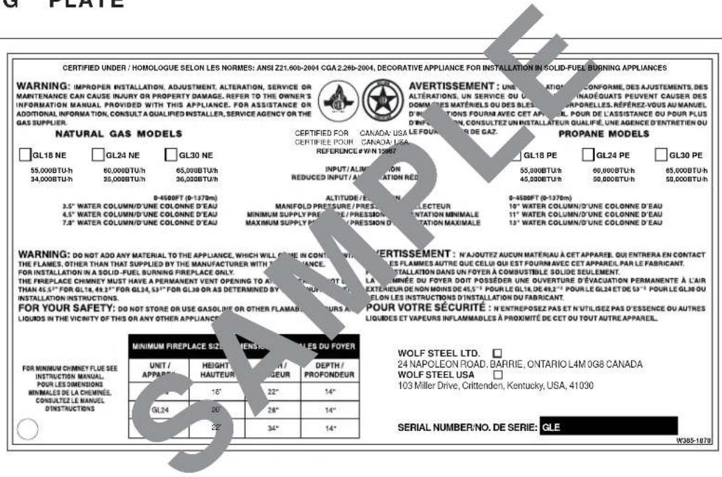
THE RATING PLATE IS CHAINED TO THE LEG OF THE BURNER BASE AND SHOULD BE TUCKED UNDER THE ENTIRE ASSEMBLY
This rating plate illustration is for reference only. Refer to the rating plate on the appliance for accurate information.
3.0 INSTALLATION
! WARNING
THIS APPLIANCE MUST BE INSTALLED IN A SOLID-FUEL BURNING FIREPLACE WITH A WORKING FLUE AND CONSTRUCTED OF NON-COMBUSTIBLE MATERIAL.
The appliance and gas logs function as a system. If the appliance is not drafting properly and spilling into the room (check with a match or a smoke stick), reposition the damper clamp until a positive draft is obtained by opening the damper. If negative pressure in home prevents having a positive draft, consult an air quality specialist.
3.1 GAS PIPING
! WARNING
DO NOT CONNECT EITHER THE WALL SWITCH, THERMOSTAT OR GAS VALVE TO ELECTRICITY (110 VOLTS).
This appliance must be isolated from the gas supply piping system by closing the individual manual shut off valve during any pressure testing of the gas supply piping system at test pressure equal to or less than 1/2 psi (3.5 kPa)
A. Centre the appliance in the fireplace opening, making sure the appliance has enough room behind it for the gas line to run behind the log set under the log support.
B. Route the gas line and sizing using piping 1/2 " diameter or greater to allow the full volume of gas to the appliance. The routing of the gas line has to be done to local and / or national codes.
C. When rigid pipe is used an ANSI approved manual shut off and a union must be installed upstream within the appliance cavity.
D. To ensure the appliance operates reliably install a sediment trap upstream of the appliance within the structures of the piping system.

E. When using propane, a regulator must be used between the tank and the outside wall of the house to ensure the line pressure does not exceed 14" w.c.
F. Check gas connections with a gas detection device to test for leaks in the system. Soapy water mixture can also be used to check for leaks.
G. Once all the gas connections are tested for leaks, start the appliance. Follow the lighting instructions to ensure the appliance is working properly before finishing.
3.2 DAMPER STOP INSTALLATION
The damper must be permanently locked in position to prevent full closure and to provide a minimum fl ue opening. Various methods for locking the damper may be used but may be restricted from region to region and it is important to know the specifics that apply to your area. For your convenience a damper stop is provided with the appliance and may be used where not prohibited by state or local codes.

Use the 3" adjustable bolt to adjust the damper to the correct opening, based on the enclosed chart.
Should the damper stop not fit, or provide the required permanent opening from the Minimum Damper Opening table, have the damper cut to provide a minimum permanent opening or install an alternate stop.
Creosote, ashes and loose paint must be cleaned from the chimney flue and firebox by a qualified chimney cleaner, before installing in a solid fuel burning appliance. Any outside air ducts and/or ash dumps in the fi replace shall be permanently closed at time of appliance installation.
If the damper stop (supplied) is not applicable the damper may be fixed open by the following method:
- Drill a hole in either end of the damper.
- Using a bolt of sufficient length and adjustment, with 2 nuts, secure to damper through the hole.
- Adjust to correct opening.
| MINIMUM DAMPER OPENING(SQUARE INCHES) | ||
| CHIMNEY HEIGHT | MASONRY APPLIANCE | FACTORY BUILT APPLIANCE |
| 6 33.8" | ||
| 8 31.2" | ||
| 10 28.7" | 22.1" | |
| 15 26.1" | 17.3" | |
| 20 23.7" | 14.5" | |
| 25 22.7" | 12.6" | |
| 30 21.6" | 11.3" | |
| 35 10.8" | ||
| 40 10.2" | ||
8
4.0 FINISHING
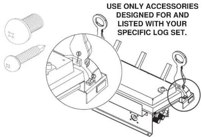
4.1 ANDIRON AND GRATE ASSEMBLY
A. With the 2 andirons laying face down, secure the grate overtop using two 1/4 -20 bolts (supplied in the manual baggie).
B. Install the grate/andiron assembly to the burner base using four 1 1/4 " self tapping screws (supplied in the manual baggie).
4.2 BATTERY INSTALLATION
A. Remove all the logs.
B. The battery pack is located at the rear right corner of the burner behind the pilot. If there is room, slide the battery pack out to the right, otherwise lift up carefully, making sure that the wires connected to the battery pack do not become entangled.
C. Unfasten the Velcro and replace the 4 AA batteries.
D. Replace battery pack and log set (see "LOG PLACEMENT" section).

4.3 LOG PLACEMENT
| WARNING |
| FAILURE TO POSITION THE LOGS IN ACCORDANCE WITH THESE DIAGRAMS OR FAILURE TO USE ONLY LOGS SPECIFICALLY APPROVED WITH THIS APPLIANCE MAY RESULT IN PROPERTY DAMAGE OR PERSONAL INJURY. |
| LOGS MUST BE PLACED IN THEIR EXACT LOCATION IN THE APPLIANCE. DO NOT MODIFY THE PROPER LOG POSITIONS, SINCE APPLIANCE MAY NOT FUNCTION PROPERLY AND DELAYED IGNITION MAY OCCUR. |
| THE LOGS ARE FRAGILE AND SHOULD BE HANDLED WITH CARE. |
Phazer™ logs, exclusive to Napoleon Appliances, provide a unique and realistic glowing effect that is different in every installation. Failure to follow these log placement instructions may cause sooting.
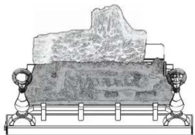
A. Place the rear log #1 onto the locating studs on the rear log support.
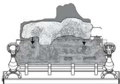
B. Position the holes on the bottom of log #2 onto the fi bre embosses shown.
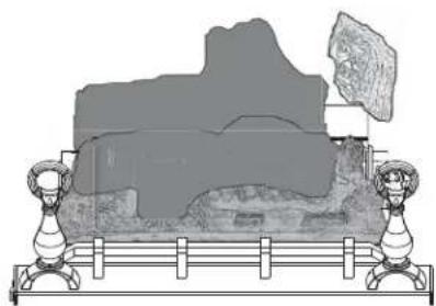
C. Position the bottom cavity of log #3 onto the bracket located in the front right corner.
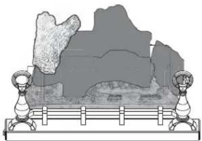
D. Position the pins on the bottom of log #4 into the holes on the left end of log #1 and the left end of log #2.
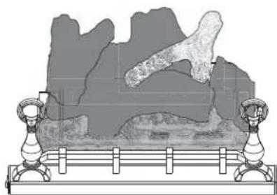
E. Place the end of log #5 on the right end of log #1. The fork in the log should straddle the knot on top of the log #2.
Log colours may vary. During the initial use of the appliance, the colours will become more uniform as colour pigments burn in during the heat activated curing process.
Positioning the logs improperly will cause flame impingement and carboning.
Blocked burner ports can cause an incorrect flame pattern, carbon deposits and delayed ignition. Use only certified Phaze™ logs available from your authorized dealer/distributor.
10
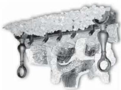
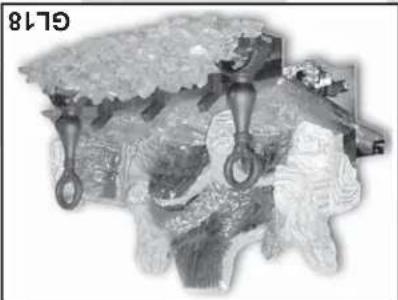
4.4 MEDIA
A. Place lava or ember rock around the base of the appliance, making sure not to block any burner ports or valve access. Retain a small amount of lava rock for step 3 and if applicable step 4.
B. Place formed charcoal lumps around the front and sides of the appliance.
C. Use remaining lava or ember rock to blend with the charcoal lumps.
D. GL30 ONLY: Sprinkle remaining lava rock onto the outer fibre ember beds to hide the seam.
IMPORTANT: DO NOT COVER FRONT SLOTS BENEATH THE ANDIRONS WITH MEDIA.
GL 18

GL 24 GL 30


4.5 LOGO PLACEMENT
Remove the backing of the logo supplied. Centre the logo on the front of the appliance, 1/2 " in from the left side, as shown.

4.6 OPTIONAL ROCK PLACEMENT
! WARNING
REAL ROCKS MUST NOT BE USED IN THIS APPLIANCE. HEAT WILL CAUSE THEM TO EXPLODE
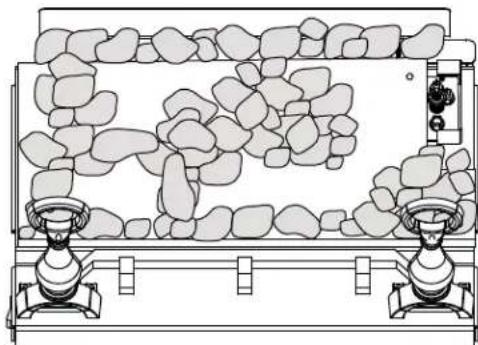
A. Begin with thin rock clusters on rear log support, then build outward in a pattern as shown. Removing a locating pin in the rear support may be required to accommodate the rock clusters. It is not necessary to use all of the rocks.
IMPORTANT: Do not block burner ports on burner surface. Do not block slots beneath or behind the andirons.
4.7 OPTIONAL REMOTE INSTALLATION (NOT SUPPLIED)
A. The remote receiver must be installed onto the bracket on the back right sides of the burner.
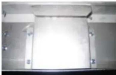
B. Bend the tab on the bracket straight and then using the double sided tape supplied with the remote kit, adhere the remote reciever to the bracket.
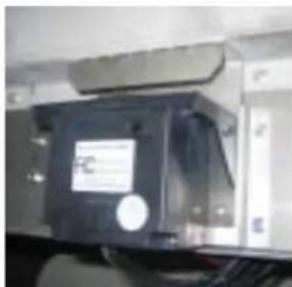
C. Hook up the wires from the remote receiver to the green and white wires on the wire harness.
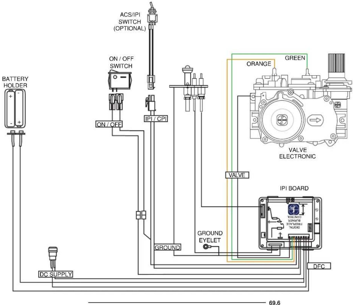
5.0 WIRING DIAGRAM
! WARNING
DO NOT WIRE 110 VOLTS TO THE VALVE OR WALL SWITCH.
This appliance comes equipped with a battery pack. Install four AA batteries into the holder and connect to the wire harness. Connect the battery holder to the wire harness before using the appliance. It must be connected to the 6 volt battery pack (supplied).
6.0 OPERATION
If the fireplace is equipped with decorative glass doors, they must be fully opened when operating this gas log set. Keep burner and control compartment clean.
6.1 OPERATING AND LIGHTING INSTRUCTIONS
WARNING
IF YOU DO NOT FOLLOW THESE INSTRUCTIONS EXACTLY, A FIRE OR EXPLOSION MAY RESULT CAUSING PROPERTY DAMAGE, PERSONAL INJURY OR LOSS OF LIFE.
ALWAYS LIGHT THE PILOT WHETHER FOR THE FIRST TIME OR IF THE GAS SUPPLY HAS RUN OUT WITH THE GLASS DOOR OPENED OR REMOVED.
When lit for the first time, the appliance will emit an odour for a few hours. This is a normal temporary condition caused by the “burn-in” of paints and lubricants used in the manufacturing process and will not occur again. After extended periods of non-operation such as following a vacation or a warm weather season, the appliance may emit a slight odour for a few hours. This is caused by dust particles in the cavity burning off. In both cases, open a window to sufficiently ventilate the room.
FOR YOUR SAFETY READ BEFORE LIGHTING:
A. Do not turn on if children or other at risk individuals are near the appliance.
B. Before operating smell all around the appliance area for gas and next to the floor because some gas is heavier than air and will settle on the floor.
C. Use only your hand to turn the gas control knob. Never use tools. If the knob will not turn by hand, do not try to repair it. Call a qualified service technician. Force or attempted repair may result in a fire or explosion.
D. Do not use this appliance if any part has been under water. Immediately call a qualified service technician to inspect the appliance and replace any part of the control system and any gas control which has been underwater.
WHAT TO DO IF YOU SMELL GAS:
- Turn off all gas to the appliance.
- Open windows.
- Do not try to light any appliance.
-
Do not touch any electric switch; do not use any phone in your building.
-
Immediately call your gas supplier from a neighbour's phone. Follow the gas supplier's instructions.
- If you cannot reach your gas supplier, call the fire department.

MANUAL SHUT-OFF
(SHOWN IN OFF POSITION)
LIGHTING INSTRUCTIONS:
- Stop! Read the above safety information on this label.
- Open the glass door if equipped.
- Remove the batteries.
- This appliance is equipped with an ignition device which automatically lights the pilot. Do not try to light the pilot by hand.
- Turn manual shutoff valve clockwise to off. Located behind the appliance.
- Wait five (5) minutes to clear out any gas. If you smell gas including near the floor, STOP! Follow "B" in the above safety information on this label. If you don't smell gas go to the next step.
- Turn manual shutoff valve counter-clockwise to on.
- Replace the batteries.
- Turn switch on and listen for ignition sound.

TO TURN OFF GAS:
- Remove the batteries.
- Turn manual shutoff valve clockwise to off. Do not force.
7.0 ADJUSTMENTS
7.1 PILOT BURNER ADJUSTMENT
Adjust the pilot screw to provide properly sized fl ame. Turn in a clockwise direction to reduce the gas fl ow.
Check Pressure Readings:
Inlet pressure can be checked by turning screw (A) counterclockwise 2 or 3 turns and then placing pressure gauge tubing over the test point. Gauge should read 7" (minimum 4.5") water column for natural gas or 13" (11" minimum) water column for propane. Check that main burner is operating on "HI".
Outlet pressure can be checked the same as above using screw (B). Gauge should read 3.5" water column for natural gas or 10" water column for propane. Check that main burner is operating on "HI".
AFTER TAKING PRESSURE READINGS, BE SURE TO TURN SCREWS CLOCKWISE FIRMLY TO RESEAL. DO NOT OVERTORQUE.
Leak test with a soap and water solution.


39.1A
7.2 VENTURI ADJUSTMENT
This appliance has an air shutter that has been factory set open according to the chart below:
Regardless of venturi orientation, closing the air shutter will cause a more yellow flame, but can lead to carboning. Opening the air shutter will cause a more blue flame, but can cause flame lifting from the burner ports. The flame may not appear yellow immediately; allow 15 to 30 minutes for the final flame colour to be established.
AIR SHUTTER ADJUSTMENT MUST ONLY BE DONE BY A QUALIFIED INSTALLER!

49.1
| LOG SET AIR SHUTTER | |
| FUEL NG LP | |
| GL18 1/8" 1/4" | |
| GL24 1/8" 5/16" | |
| GL30 1/8" 3/8" | |
7.3 FLAME CHARACTERISTICS
It's important to periodically perform a visual check of the pilot and burner flames. Compare them to the illustrations provided. If any flames appear abnormal call a service person. PILOT


54.1A
8.0 MAINTENANCE
MAIN WARNING
TURN OFF THE GAS AND REMOVE BATTERIES BEFORE SERVICING THE APPLIANCE.
APPLIANCE MAY BE HOT, DO NOT SERVICE UNTIL APPLIANCE HAS COOLED.
DO NOT USE ABRASIVE CLEANERS.
CAUTION: Label all wires prior to disconnection when servicing controls. Wiring errors can cause improper and dangerous operation. Verify proper operation after servicing. This appliance and its venting system should be inspected before use and at least annually by a qualified service person. The appliance area must be kept clear and free of combustible materials, gasoline or other flammable vapours and liquids. The flow of combustion and ventilation air must not be obstructed.
- In order to properly clean the burner and pilot assembly, remove the logs, rocks and/or glass to expose both assemblies.
- Keep the control compartment, media, burner, air shutter opening and the area surrounding the appliance clean by vacuuming or brushing, at least once a year.
- Check to see that all burner ports are burning. Clean out any of the ports which may not be burning or are not burning properly.
- Check to see that the pilot flame is large enough to engulf the flame sensor and/or thermocouple / thermopile as well as reaches the burner.
- Replace the cleaned logs, rocks or glass. Failure to properly position the media may cause carboning which can be distributed in the surrounding living area.
- Check to see that the main burner ignites completely on all openings when turned on. A 5 to 10 second total light-up period is satisfactory. If ignition takes longer, consult your local authorized dealer / distributor.
- Visually inspect the appliance for carbon build up. Using a small whisk or brush, brush off the carbon and vacuum up or sweep into garbage.
- Check to see that the appliance is venting correctly. Ensure chimney system is safe and unobstructed.
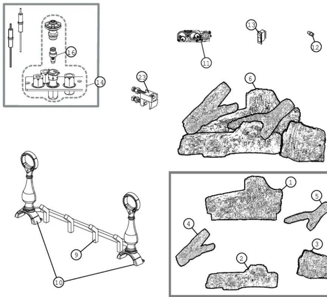
9.0 REPLACEMENTS
Contact your dealer or the factory for questions concerning prices and policies on replacement parts. Normally all parts can be ordered through your Authorized dealer / distributor.
FOR WARRANTY REPLACEMENT PARTS, A PHOTOCOPY OF THE ORIGINAL INVOICE WILL BE
REQUIRED TO HONOUR THE CLAIM.
When ordering replacement parts always give the following information:
- Model & Serial Number of appliance
• Installation date of appliance - Part number
• Description of part - Finish
* IDENTIFIES ITEMS WHICH ARE NOT ILLUSTRATED. FOR FURTHER INFORMATION, CONTACT YOUR AUTHORIZED DEALER.

FAILURE TO POSITION THE PARTS IN ACCORDANCE WITH THIS MANUAL OR FAILURE TO USE ONLY PARTS SPECIFICALLY APPROVED WITH THIS APPLIANCE MAY RESULT IN PROPERTY DAMAGE OR PERSONAL INJURY.
41.1
COMPONENTS
| REF NO. | GAS LOGS DESCRIPTION | |
| 1 W135-020 | 5 #1 - REAR LOG | |
| 2 W135-020 | 6 #2 - MIDDLE LOG | |
| 3 W135-020 | 7 #3 - RIGHT LOG | |
| 4 W135-020 | 8 #4 - LEFT LOG | |
| 5 W135-021 | 8 #5 - CROSSOVER LOG | |
| 6 GL-644 LOG SET | ||
| 7* W135-025 | 51 GL30 RIGHT EXTENSION LOG | |
| 8* W135-025 | 52 GL30 LEFT EXTENSION LOG | |
| 9 W185-002 | 4 GL18 GRATE | |
| 9 W185-002 | 0 GL24 GRATE | |
| 9 W185-002 | 3 GL30 GRATE | |
| 10 W715-06 | 28 GL18 / 24 ANDIRONS | |
| 10 W715-06 | 29 GL30 ANDIRONS | |
| 11 W725-00 | 62 SIT VALVE - NG | |
| 11 W725-00 | 63 SIT VALVE - LP | |
| 12 W456-00 | 28 #28 ORIFICE - NG (GL18) | |
| 12 W456-00 | 45 #45 ORIFICE - LP (GL18) | |
| 12 W456-00 | 26 #26 ORIFICE -NG (GL24) | |
| 12 W456-00 | 44 #44 ORIFICE - LP (GL24) | |
| 12 W456-00 | 22 #22 ORIFICE - NG (GL30) | |
| 12 W456-00 | 43 #43 ORIFICE - LP (GL30) | |
| 13 W660-00 | 23 ON / OFF SWITCH | |
| 14 W010-18 | 65 PILOT ASSEMBLY - NG | |
| 14 W010-18 | 66 PILOT ASSEMBLY - LP | |
| 15* W385-00 | 334 NAPOLEON LOGO | |
| 16 W455-00 | 69 PILOT INJECTOR - NG | |
| 16 W45500 | 68 PILOT INJECTOR - LP | |
| 17* W190-00 | 29 IPI BOARD | |
| 20* W010-1 | 260 FIBRE BURNER ASSEMBLY | |
| 21* W550-00 | 006 LAVA ROCK | |
| 22* W550-00 | 002 CHARCOAL LUMPS | |
| 23 W010-12 | 88 DAMPER STOP | |
| ACCESSORIES | ||
| REF NO. | GAS LOGS DESCRIPTION | |
| 24* GD-660 | REMOTE WALL SWITCH W/20" WIRE | |
| 26* W660-0026 | PROGRAMMABLE TIMER | |
| 27* F45 ON/OFF REMOTE | ||
| 27* F45-6 ON/OFF REMOTE -BULK | ||
| 28* MKRY GREY RIVER ROCKS | ||
| 28* MKRM MULTI-COLOURED RIVER ROCKS | ||
10.0 TROUBLE SHOOTING
| MAINWARNINGCE |
| TURN OFF THE GAS AND ELECTRICAL POWER BEFORE SERVICING THE APPLIANCE. |
| APPLIANCE MAY BE HOT, DO NOT SERVICE UNTIL APPLIANCE HAS COOLED. |
| DO NOT USE ABRASIVE CLEANERS. |
SYMPTOM PROBLEM TEST SOLUTION
Pilot will not light. Makes noise with no spark at pilot burner.  | Wiring. - Verify the wire for the sensor and the wire for the ignitor are connected to the correct terminals (not reversed) on the module. NOTE: Sensor has 3/16" connection and ignitor has 1/8" connection. | |
| Loose connection. - Verify no loose connections, electrical shorts in the wiring or ground out to any metal object. | ||
| Module. - Turn the ON/OFF switch to the "OFF" position. Remove the igniter wire from the module. Place the ON/OFF switch to the "ON" position. Hold a grounded wire about 3/16" away from the ignitor (spark) terminal on the module. If no spark the ignitor terminal module must be replaced. If there is a spark the ignitor terminal is fine. | ||
| Electrode. - Inspect pilot assembly for a shorted wire or cracked insulator around the electrode. | ||
| Igniter Spark gap is incorrect. | - Spark gap of the ignitor to the pilot should be 1/8". | |
| Battery. - Check batteries. | ||
| A shorted or loose Connection. | - Remove and reinstall the wiring harness that plugs into the module. Remove and verify continuity of each wire in wiring harness. | |
| Improper switch wiring. - Troubleshoot the system with the simplest ON/OFF switch. | ||
| Module is not grounded. | - Verify the valve and pilot assemblies are properly grounded to the metal chassis of the appliance or log set. | |
| Pilot sparks but will not light. | Gas supply. | - Verify that the incoming gas line ball valve is "Open". Verify that the inlet pressure reading is within acceptable limits, inlet pressures must not exceed 14" W.C. |
| Out of propane gas. | - Fill the tank. | |
SYMPTOM PROBLEM TEST SOLUTION
| Carbon is being deposited on glass, logs, rocks, media or combustion chamber surfaces. | Air shutter has become blocked. | - Ensure air shutter opening is free of lint or other obstructions. |
| Flame is impinging on the glass, logs, rocks, media or combustion chamber. | - Check that the glass, logs, rocks or media are correctly positioned and remove them from direct flame. - Open air shutter to increase the primary air. - Check the input rate: check the manifold pressure and orifice size as specified by the rating plate values. | |
| Continues to spark and pilot lights, but main burner will not light. | Short or loose connection in sensor rod. | - Verify all connections. Verify the connections from the pilot assembly are tight; also verify these connections are not grounding out to any metal. |
| Poor flame rectification or contaminated sensor rod. | - Verify the flame is engulfing the sensor rod. This will increase the flame rectification. Verify correct pilot orifice is installed and inlet gas specifications to manual. (Remember, the flame carries the rectification current, not the gas. If the flame lifts from pilot hood, the circuit is broken. A wrong orifice or too high of an inlet pressure can cause the pilot flame to lift.) The sensor rod may need cleaning. | |
| Poor grounding between pilot assembly and gas valve. | - Verify that the wire harness is firmly connected to module Verify that the ceramic insulator around the sensor rod is not cracked, damaged, or loose. Verify the connection from the sensor rod to the sensor wire. | |
| Damaged pilot or sensor rod. | - Clean sensor rod with an emery cloth to remove any contamination that may have accumulated on the sensor rod. Verify continuity with multimeter with ohms set at the lowest range. Check for shorted wire or cracked insulator. | |
| Pilot lights Stops sparking / pilot remains lit but burner will not turn on. | Wiring / Connection. - Inspect all wires, ensure good tight connections. Verify that all wiring is installed exactly as specified. | |
| Wiring harness. - Inspect the wiring harness, and verify the harness is tightly connected to the module. Verify that all wires are connected in the right order. See “WIRING DIAGRAM” section. | ||
| Exhaust fumes smelled in room, headaches. | Appliance is spilling. - Check for chimney blockage - Check that chimney is installed to building code. - Room is in negative pressure; increase fresh air supply - Check damper positioning | |
42.25 2
11.0 WARRANTY
NAPOLEON® products are manufactured under the strict Standard of the world recognized ISO 9001 : 2008 Quality Assurance Certifi cate.
NAPOLEON® products are designed with superior components and materials assembled by trained craftsmen who take great pride in their work. Once assembled the complete log set is thoroughly inspected by a qualified technician before packaging to ensure that you, the customer, receive the quality product that you expect from NAPOLEON®.
NAPOLEON® GAS LOG SET LIFETIME LIMITED WARRANTY
The Phazer™ logs in your new Napoleon® gas log set are warranted against defects for as long as you own the appliance.
Electrical (millivolt) components, burner and wearable parts such as the gas valve, thermal switch, switches, wiring, remote control, ignitor, gasketing, and pilot assembly are covered and Napoleon® will provide replacement parts free of charge during the first year of the lifetime limited warranty.* * Construction of models vary. Warranty applies only to components included with your specific appliance.
CONDITIONS AND LIMITATIONS
NAPOLEON® warrants its products against manufacturing defects to the original purchaser only. Registering your warranty is not necessary. Simply provide your proof of purchase along with the model and serial number to make a warranty claim. NAPOLEON® reserves the right to have its representative inspect any product or part thereof prior to honouring any warranty claim. Provided that the purchase was made through an authorized NAPOLEON® dealer your appliance is subject to the following conditions and limitations: Warranty coverage begins on the date of original installation.
This factory warranty is non-transferable and may not be extended whatsoever by any of our representatives.
Installation must be done in accordance with the installation instructions included with the product and all local and national building and tire codes. This limited warranty does not cover damages caused by misuse, lack of maintenance, accident, alterations, abuse or neglect and parts installed from other manufacturers will nullify this warranty.
This limited warranty further does not cover any scratches, dents, corrosion or discoloring caused by excessive heat, abrasive and chemical cleaners nor chipping on porcelain enamel parts, mechanical breakage of PHAZER™ logs and embers.
In the first year only, this warranty extends to the repair or replacement of warranted parts which are defective in material or workmanship provided that the product has been operated in accordance with the operation instructions and under normal conditions. After the first year, with respect to this President's Lifetime Limited Warranty, NAPOLEON® may, at its discretion, fully discharge all obligations with respect to this warranty by refunding to the original warranted purchaser the wholesale price of any warranted but defective part(s).
NAPOLEON® will not be responsible for installation, labour or any other expenses related to the reinstallation of a warranted part and such expenses are not covered by this warranty.
Notwithstanding any provisions contained in the President's Lifetime Limited Warranty, NAPOLEON'S responsibility under this warranty is defined as above and it shall not in any event extend to any incidental, consequential or indirect damages.
This warranty defines the obligations and liability of NAPOLEON® with respect to the NAPOLEON® gas logs and any other warranties expressed or implied with respect to this product, its components or accessories are excluded.
NAPOLEON® neither assumes, nor authorizes any third party to assume, on its behalf, any other liabilities with respect to the sale of this product.
Any damages to the burner or logs or other components due to water, weather damage, long periods of dampness, condensation, damaging chemicals or cleaners will not be the responsibility of NAPOLEON®.
All parts replaced under the President's Limited Lifetime Warranty Policy are subject to a single claim.
During the first 10 years NAPOLEON® will replace or repair the defective parts covered by the lifetime warranty at our discretion free of charge. From 10 years to life, NAPOLEON® will provide replacement parts at 50% of the current retail price.
All parts replaced under the warranty will be covered for a period of 90 days from the date of their installation.
The manufacturer may require that defective parts or products be returned or that digital pictures be provided to support the claim. Returned products are to be shipped prepaid to the manufacturer for investigation. If a product is found to be defective, the manufacturer will repair or replace such defect.
Before shipping your appliance or defective components, your dealer must obtain an authorization number. Any merchandise shipped without authorization will be refused and returned to sender.
Shipping costs are not covered under this warranty.
Additional service fees may apply if you are seeking warranty service from a dealer.
Labour travel, diagnostic tests, shipping and other related charges are not covered by this warranty.
ALL SPECIFICATIONS AND DESIGNS ARE SUBJECT TO CHANGE WITHOUT PRIOR NOTICE DUE TO ON-GOING PRODUCT IMPROVEMENTS. NAPOLEON® IS A REGISTERED TRADEMARK OF WOLF STEEL LTD.
12.0 SERVICE HISTORY
Appliance Service History This heater must be serviced annually depending on usage.
| Date | Dealer Name | Service Technician Name | Service Performed | Special Concerns |
22
13.0 NOTES
44
じゅ
441
43.1
TOÛTES LES SPECIFICATIONS ET LES CONCEPTIONS SOUT SUJETES A MODIFICATIONS SAUS PREAVES EN RAISON DES AMéliORATIONS CONSANTALES APPORTÉES AU PRODUIT, NAPOLEONQ EST UNE MARQUE DE COMMERCE DÉPOSE DE WOLF STEEL LITE.
CONDITIONS ET LIMITATIONS
| No DE REF BUCHES A GAZ DESCRIPTION | |
| ACCESSORIES | |
| 24* GD-660 INTERUPETUR MURAL AVEC FIL DE 20" | |
| 26* WB60-0026 MUNTERE PROGRAMMABLE | |
| 27* F45 TELECOMMANDE MARCHE/ARRET | PAQUET |
| 27* F45 TELECOMMANDE MARCHE/ARRET | |
| 27* F45 TELECOMMANDE MARCHE/ARRET | PAQUET |
| 28* MKRY ROCHES DE RIVIERE MULTICOLORES | |
| 28* MKRY ROCHES DE RIVIERE GRISSES | |
| 28* MKRY ROCHES DE RIVIERE GRISSES | |
| No DE REF BUCHES A GAZ DESCRIPITION | |
| 1 W135-0205 BCHE ARRIFERRE #1 | |
| 2 W135-0206 BCHE CENTRALE #2 | |
| 3 W135-0207 BCHE DROITLE #3 | |
| 4 W135-0208 BCHE CAUCHE #4 | |
| 5 W135-0218 BCHE TRANSVERSALLE #5 | |
| 6 GL-644 ENSEMABLE DE BUDCHES | |
| 7 * W135-0251 BCHE DEXTREMITTE DROITLE - GL30 | |
| 8 * W135-0252 BCHE DEXTREMITTE CAUCHE - GL30 | |
| 9 W185-0020 CHENET POUR LE GL24 | |
| 10 W175-0628 BORNES DE CHENET POUR LE GL18 / 24 | |
| 11 W357-0001 ALUMNEUR PILEZO ET ECROU | |
| 11 W725-0062 SOUPAPE SIT - GN | |
| 12 W456-0045 GL18 - UNICECTEUR #45 - PL | |
| 12 W456-0044 GL24 - UNICECTEUR #44 - PL | |
| 12 W456-0022 GL30 - UNICECTEUR #22 - GN | |
| 12 W456-0043 GL30 - UNICECTEUR #43 - PL | |
| 13 W660-0023 INTERRUPITERUR MARCHE/ARRET | |
| 14 W101-1865 ASSEMBLAGE DE VELLUEUSE - NG | |
| 14 W101-1865 ASSEMBLAGE DE VELLUEUSE - PL | |
| 15 * W385-0334 LOGO NAPOLETON | |
| 16 W455-0069 PILOT UNICECTOR - NG | |
| 16 W455-0068 PILOT UNICECTOR - LP | |
| 17 * W190-0029 PANNEAU IPI | |
| 20 * W101-1260 RECOUVREMENT EN FIBRÉ DE CERAMIOUE | |
| 21 * W550-0002 MORCEAUX DE CHARBON | |
| 22 * W550-0002 MORCEAUX DE CHARBON | |
| 23 W101-1288 BUTE DE REGISTRE | |
41.7
OMETTRE DE POSITIONNER LES PICES CONFORMENT AU MANUEL OU UTILISER UNIVEMENT DES PICES SPECIFICATION APPROVEES POUR CET APPAREL PEUT CAUSER DES DOMAÇES MATERIALS OU DES BLESSURES CORPORÉLLES.
i AVERTISSEMENT
* IDENTIFIE LES ARTICLES QUI NE SONT PAS ILLUSTRES. POUR PLUS D'INFORMATION, CONTACTE VOTRE DETAILANT AUTORISE.
• Fini
service.
| ENS.DE | VOLT D.AIR |
| BUCKHES | |
| FUEL NG LIP | |
| GL18 1/8" 1/4" | |
| GL24 1/8" 5/16" | |
| GL30 1/8" 3/8" | |

LE RECIALE DU VOLET D'AIR DOIT ETRE EXECUTE PAR UN TECHNICIAN OU INSTALLATEUR QUALIFI!
NE PAS UTILISER DE VRALS ROSCHES DANS CET APPAREL. LA CHALEUR LES FERA EXPLOSER.
i WARNING
4.6 PLACEMENT DE LA ROCHES OPTIONNEELE

shown.
Remove the backing of the logo supplied. Centre the logo on the front of the appliance, 1/2 in from the left side, as
4.5 MISE EN PLACE DU LOGO

GL 24 GL 30

GIL18
joint.
D. GL30 ONLY: Sprinkle remaining lava rock onto the outer fibre ember beds to hide the seam.
avant droit.
comme illustré.

support a buches arriere.
positionnement du
1 sur les tiges de
A. Placez la buche arriere

PEUT CAUSER DES DOMMAGES MATERIALS OU DES BLESSURES CORPORÉLLES.
D'UTILISER UNIQUITEMT DES BUCHES SPECIFIQUEMENT APPROUVEES POUR CET APPAREL
OMETTRE DE POSITIONNER LES BUCHES CONFORMEMENT AUX SCHEMAS OU OMETTRE
i AVERTISSEMENT
4.3 DISPOSITION DES BUCHES

This appliance must be isolated from the gas supply piping system by closing the individual manual shut off value during any pressure testing of the gas supply piping system at test pressure equal to or less than 1/2 psi.
L.AUMENTATION ELECTRIOUE (110 VOLTs).
NE RACCORDEZ PAS LINTERUPTEUR MURAL, LE THEMOSTAT OU LA SOUPAPE DE GAZ A
i AVERTISSEMENT
3.1 CONDUITE DE GAZ
2.4 PLACQUE D 3 HOMOLOGATION
| LOG SET HEIGHT WIDTH DEPTH | |
| GL18 18" 22" 14" | |
| GL24 20" 28" 14" | |
| GL30 22" 34" 14" | |
ww.w.nf.certified.ory

NATIONAL FILEPLACE INSTITUTE.
Wolf Steel Ltd., 24 Napoleon Rd., Barrie, ON, L4M 068 Canada /


DANS DES APPARELIS A COMBUSTIBLE SOLIDE.
HOMOLOGUES SELON LES NORMES ANSI Z21.60 / CSA 2.26 OUR LES APPAREILS DECOPARTIFS AU GAZ, POUR INSTALATION
'DoPERATION
INSTALLATION ET INSTRUCTIONS
FOVERS DE QUAUTE

NE LAISSEZ PAS LES ENFAANTS OU AUTRES INDIVIDUS À RISQUE SEULS À PROXIMATE DE L'APPAREL.
PROPRIETAIRE : CONSERVEZ CE MANUEL POUR CONSULTATION ULTERIEURÉ.
INSTALLATEUR : LASSEZ CE MANUEL AVEC L.APPAREL.

- INSTALLATION AND OPERATING INSTRUCTIONS
- SAFETY INFORMATION
- WARNING
- 1.0 INSTALLATION OVERVIEW
- 2.0 INTRODUCTION
- 2.1 GENERAL INSTRUCTIONS
- 2.2 GENERAL INFORMATION
- 2.3 MINIMUM APPLIANCE SIZE
- 2.4 RATING PLATE
- 3.0 INSTALLATION
- THIS APPLIANCE MUST BE INSTALLED IN A SOLID-FUEL BURNING FIREPLACE WITH A WORKING FLUE AND CONSTRUCTED OF NON-COMBUSTIBLE MATERIAL
- 3.1 GAS PIPING
- DO NOT CONNECT EITHER THE WALL SWITCH, THERMOSTAT OR GAS VALVE TO ELECTRICITY (110 VOLTS)
- 3.2 DAMPER STOP INSTALLATION
- 4.0 FINISHING
- 4.1 ANDIRON AND GRATE ASSEMBLY
- 4.2 BATTERY INSTALLATION
- 4.3 LOG PLACEMENT
- 4.4 MEDIA
- 4.5 LOGO PLACEMENT
- 4.6 OPTIONAL ROCK PLACEMENT
- 4.7 OPTIONAL REMOTE INSTALLATION (NOT SUPPLIED)
- 5.0 WIRING DIAGRAM
- 6.0 OPERATION
- 6.1 OPERATING AND LIGHTING INSTRUCTIONS
- FOR YOUR SAFETY READ BEFORE LIGHTING
- WHAT TO DO IF YOU SMELL GAS
- LIGHTING INSTRUCTIONS
- TO TURN OFF GAS
- 7.0 ADJUSTMENTS
- 7.1 PILOT BURNER ADJUSTMENT
- CHECK PRESSURE READINGS
- AFTER TAKING PRESSURE READINGS, BE SURE TO TURN SCREWS CLOCKWISE FIRMLY TO RESEAL. DO NOT OVERTORQUE
- 7.2 VENTURI ADJUSTMENT
- AIR SHUTTER ADJUSTMENT MUST ONLY BE DONE BY A QUALIFIED INSTALLER
- 7.3 FLAME CHARACTERISTICS
- 8.0 MAINTENANCE
- MAIN WARNING
- 9.0 REPLACEMENTS
- REQUIRED TO HONOUR THE CLAIM
- 10.0 TROUBLE SHOOTING
- 11.0 WARRANTY
- NAPOLEON® GAS LOG SET LIFETIME LIMITED WARRANTY
- CONDITIONS AND LIMITATIONS
- 12.0 SERVICE HISTORY
- 13.0 NOTES
- CONDITIONS ET LIMITATIONS
- LE RECIALE DU VOLET D'AIR DOIT ETRE EXECUTE PAR UN TECHNICIAN OU INSTALLATEUR QUALIFI
- 4.5 MISE EN PLACE DU LOGO
- 1 SUR LES TIGES DE
- 2.4 PLACQUE D 3 HOMOLOGATION
Brand : Napoleon
Model : GL30NE
Category : Fireplace