Ascent BLX46 - Fireplace Napoleon - Free user manual and instructions
Find the device manual for free Ascent BLX46 Napoleon in PDF.

| Product Type | Linear Gas Fireplace |
| Brand | Napoleon |
| Model | Ascent BLX46 |
| Fuel | Natural gas or propane (convertible) |
| Max. Heat Output | 28,000 BTU/h (NG) / 26,500 BTU/h (propane) |
| Min. Heat Output | 22,000 BTU/h (NG) / 21,000 BTU/h (propane) |
| Minimum Supply Pressure | 4.5" w.c. (NG) / 11" w.c. (propane) |
| Maximum Supply Pressure | 7" w.c. (NG) / 13" w.c. (propane) |
| Dimensions (Width) | 46" (1168 mm) |
| Venting System | Direct vent vertical or horizontal (4" inner / 7" outer) |
| Ignition | Electronic with remote control (millivolt system available) |
| Main Features | Gas burner, intermittent pilot, remote control, optional blower |
| Glass Material | Heat-resistant ceramic glass |
| Included Accessories | Safety barrier, decorative log set (driftwood, birch or oak) |
| Safety | Automatic shutoff if pilot goes out, child safety barrier, CO detector recommended |
| Maintenance | Regular glass cleaning, annual inspection by a professional |
| Warranty | Lifetime limited warranty on combustion chamber and heat exchanger |
| Standards | CSA certified, approved for mobile homes |
| Repairability | Replacement parts available (glass, logs, remote, valves) |
Frequently Asked Questions - Ascent BLX46 Napoleon
User questions about Ascent BLX46 Napoleon
0 question about this device. Answer the ones you know or ask your own.
Ask a new question about this device
Download the instructions for your Fireplace in PDF format for free! Find your manual Ascent BLX46 - Napoleon and take your electronic device back in hand. On this page are published all the documents necessary for the use of your device. Ascent BLX46 by Napoleon.
USER MANUAL Ascent BLX46 Napoleon
Failure to follow safety warnings exactly could result in serious injury, death, or property damage.
- Do not store or use gasoline or other fl ammable vapours and liquids in the vicinity of this or any other appliance.
-WHAT TO DO IF YOU SMELL GAS:
- Do not try to light any appliance.
- Do not touch any electrical switch; do not use any phone in your building.
- Leave the building immediately.
- Immediately call your gas supplier from a neighbour's phone. Follow the gas supplier's instructions.
- If you cannot reach your gas supplier, call the fire department.
- Installation and service must be performed by a qualified installer, service agency, or the supplier.
This appliance may be installed in an aftermarket, permanently located, manufactured home (USA only) or mobile home, where not prohibited by local codes.
This appliance is only for use with the type of gas indicated on the rating plate. This appliance is not convertible for use with other gases, unless a certifi ed kit is used.
INSTALLER: Leave this manual with the appliance. CONSUMER: Retain this manual for future reference.
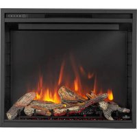
Ascent™ Linear Premium Series
(BLX56 illustrated)
natural_image
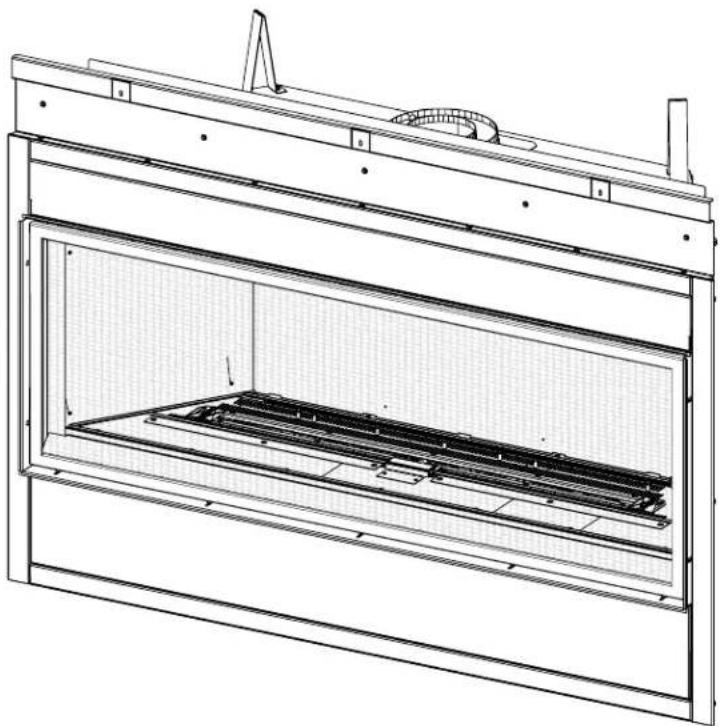
Technical line drawing of a mechanical enclosure or enclosure with internal structural components (no text or symbols)FOR INDOOR USE ONLY
CERTIFIED TO THE CANADIAN AND AMERICAN NATIONAL STANDARDS: CSA 2.22 AND ANSI Z21.50 FOR VENTED DECORATIVE GAS APPLIANCES

BARRIER


PLACE SERIAL NUMBER LABEL ON THE OWNER'S MANUAL
Wolf Steel Ltd., 24 Napoleon Rd., Barrie, ON, L4M 0G8 Canada / 103 Miller Drive, Crittenden, Kentucky, USA, 41030
Phone 1 (866) 820-8686 • www.napoleon.com • hearth@napoleon.com
! WARNING
- This appliance is hot when operated and can cause severe burns if contacted.
- Any changes or alterations to this appliance or its controls can be dangerous and is prohibited.
- Do not operate appliance before reading and understanding operating instructions. Failure to operate appliance according to operating instructions could cause fire or injury.
- Ensure the glass door is opened or removed when lighting the pilot for the first time and when the gas supply has run out.
- Risk of fire or asphyxiation, do not operate appliance with fixed glass removed and never obstruct the front opening of the appliance.
-
Do not connect 110 volts to the control valve, with the exception of models; GSST8 and GT8.
-
Risk of burns. The appliance should be turned off and cooled before servicing.
- Do not install damaged, incomplete or substitute components.
- Risk of cuts and abrasions. Wear protective gloves, protective footwear, and safety glasses during installation. Sheet metal edges may be sharp.
- Do not burn wood or other materials in this appliance.
- Provide adequate ventilation and combustion air. Provide adequate accessibility clearance for servicing and operating the appliance.
- High pressure will damage valve. Disconnect gas supply piping before pressure testing gas line at test pressures above 1/2 psig. Close the manual shut-off valve before pressure testing gas line at test pressures equal to or less than 1/2 psig (35mb).
- The appliance must not be operated at temperatures below freezing (32°F / 0°C). Allow the appliance to warm to above freezing prior to operation, with the exception of the outdoor models; these appliances are suitable for 0°F / -18°C.
- Children and adults should be alerted to hazards of high surface temperature and should stay away to avoid burns or clothing ignition.
- Young children should be carefully supervised when they are in the same room as the appliance. Toddlers, young children and others may be susceptible to accidental contact burns. A physical barrier is recommended if there are at risk individuals in the house. To restrict access to an appliance or stove, install an adjustable safety gate to keep toddlers, young children and other at risk individuals out of the room and away from hot surfaces.
- Clothing or other fl ammable material should not be placed on or near the appliance.
- Due to high temperatures, the appliance should be located out of traffic and away from furniture and draperies.
- Furniture or other objects must be kept a minimum of 4 feet (1.22m) away from the front of the appliance.
- Ensure you have incorporated adequate safety measures to protect infants/toddlers from touching hot surfaces.
- Even after the appliance is off, it will remain hot for an extended period of time.
- Check with your local hearth specialty dealer for safety screens and hearth guards to protect children from hot surfaces. These screens and guards must be fastened to the floor.
- Any safety screen, guard or barrier removed for servicing the appliance, must be replaced prior to operating the appliance.
- It is imperative that the control compartments, burners and circulating blower and its passageway in the appliance and venting system are kept clean. The appliance and its venting system should be inspected before use and at least annually by a qualified service person. More frequent cleaning may be required due to excessive lint from carpeting, bedding material, etc. The appliance area must be kept clear and free from combustible materials, gasoline and other flammable vapours and liquids.
- If the appliance shuts off, do not re-light until you provide fresh air. If appliance keeps shutting off, have it serviced. Keep burner and control compartment clean.
- Under no circumstances should this appliance be modified.
- Do not allow wind or fans to blow directly into the appliance. Avoid any drafts that alter burner flame patterns.
HOT GLASS WILL CAUSE BURNS.
DO NOT TOUCH GLASS UNTIL COOLED.
NEVER ALLOW CHILDREN TO TOUCH GLASS.
A barrier designed to reduce the risk of burns from the hot viewing glass is provided with this appliance and must be installed for the protection of children and other at-risk individuals.
! DANGER


WARNING
- Do not use a blower insert, heat exchanger insert or other accessory not approved for use with this appliance.
- This appliance must not be connected to a chimney fl ue pipe serving a separate solid fuel burning appliance.
- Do not use this appliance if any part has been under water. Immediately call a qualified service technician to inspect the appliance and to replace any part of the control system and any gas control which has been under water.
- Do not operate the appliance with the glass door (if equipped) removed, cracked or broken. Replacement of the glass should be done by a licensed or qualified service person.
- Do not strike or slam shut the appliance glass door, if equipped.
- Only doors / optional fronts certified with the appliance are to be installed on the appliance.
- Keep the packaging material out of reach of children and dispose of the material in a safe manner. As with all plastic bags, these are not toys and should be kept away from children and infants.
- Carbon or soot should not occur in a vent free appliance as it can distribute into the living area of your home. If you notice any signs of carbon or soot, immediately turn off your appliance and arrange to have it serviced by a qualified technician before operating it again.
- If equipped, the screen must be in place (closed) when the appliance is in operation.
- When equipped with pressure relief doors, they must be kept closed while the appliance is operating to prevent exhaust fumes containing carbon monoxide, from entering into the home. Temperatures of the exhaust escaping through these openings can also cause the surrounding combustible materials to overheat and catch fire.
- Carbon monoxide poisoning may lead to death; early signs of carbon monoxide poisoning resemble the flu, with headache, dizziness and/or nausea. If you have these signs, the appliance may not be working properly. Get fresh air at once! Have appliance serviced. Some people; pregnant women, persons with heart or lung disease, anemia, those under the influence of alcohol, those at high altitudes are more affected by carbon monoxide than others. Failure to keep the primary air opening(s) of the burner(s) clean may result in sooting and property damage.
- As with any combustion appliance, we recommend having your appliance regularly inspected and serviced as well as having a Carbon Monoxide Detector installed in the same area to defend you and your family against Carbon Monoxide (not applicable for outdoor appliances).
- Ensure clearances to combustibles are maintained when building a mantel or shelves above the appliance. Elevated temperatures on the wall or in the air above the appliance can cause melting, discolouration or damage to decorations, a TV or other electronic components.
- For appliances equipped with a safety barrier; if the barrier becomes damaged, the barrier shall be replaced with the manufacturer's barrier for this appliance.
• Installation and repair should be done by a qualified service person. It is imperative that control compartments, burners and circulating air passageways of the appliance be kept clean.
- For outdoor products only: this appliance must not be installed indoors or within any structure that prevents or inhibits the exhaust gases from dissipating in the outside atmosphere.
- If applicable, the millivolt version of this appliance uses and requires a fast acting thermocouple. Replace only with a fast acting thermocouple supplied by Wolf Steel Ltd.

WARNING: This product can expose you to chemicals including lead and lead compounds, which are known to the State of California to cause cancer, and chemicals including carbon dioxide, which are known to the State of California to cause birth defects or other reproducibility harm. For more information, go to www.P65Warnings.ca.gov.

WARNING

FIRE RISK HAZARD / DELAYED IGNITION
High supply pressure will damage the valve / controls.

Disconnect the appliance main gas valve/control from the supply piping when pressure testing that system at pressures in excess of 1/2 psi (3.5 kPa).
Isolate the appliance with it's shut off valve during any pressure testing of the supply piping at pressures equal to or less than 1/2 psi (3.5 kPa).

1.0 general information 5
1.1 rates and efficiencies 5
1.2 installation checklist 6
1.3 installation overview 7
1.4 rating plate information 9
1.5 mobile home installation 9
1.6 hardware list 10
2.0 dimensions 11
2.1 optional heat management system 12
3.0 venting requirements 13
3.1 BLX42/46 14
3.2 BLX56 15
3.3 typical venting installation 16
3.4 special vent installation (periscope termination) 17
3.5 4/7" vent clearance to combustibles (BLX56) 17
3.5.1 converting from 5/8" to 4/7" venting (BLX56) 18
3.6 minimum air terminal location clearances 19
3.7 vent application flow chart 20
3.8 definitions 20
3.9 elbow vent length values 20
3.10 horizontal termination 21
3.11 vertical termination 23
3.12 vent shield installation 25
4.0 rough framing 26
4.1 minimum framing dimensions 27
5.0 venting installation 29
5.1 horizontal installation 30
5.2 vertical installation 31
5.3 using either flexible or rigid vent components 32
5.4 using flexible vent components 32
5.4.1 horizontal air terminal installation 32
5.4.2 vertical air terminal installation 33
5.4.3 appliance vent connection 33
5.5 using rigid vent components 34
5.5.1 horizontal air terminal installation 34
5.5.2 vertical air terminal installation 35
5.5.3 restricting vertical vents 36
5.6 vertical through existing chimney (BLX42/46) 37
6.0 electrical information 38
6.1 hard wiring connection 38
6.2 receptacle wiring diagram 38
6.3 electronic wiring diagram 38
6.4 initializing the transmitter / battery holder for the first time 39
6.5 wiring diagram 40
7.0 gas installation 41
8.0 operation 42
8.1 pilot on demand 43
9.0 finish framing 44
9.1 nailing tab installation 44
9.2 flush 45
9.3 recessed 46
9.4 minimum clearance to combustible enclosures 47
9.5 alcove enclosure 48
10.0 finishing 49
10.1 log placement 49
10.1.1 BLX42 log placement 49
10.1.2 BLX46 log placement 49
10.2.1 BLX56 log placement 50
10.2 door hanger trim installation 50
10.3 installing the finishing trim 51
10.4 installing non-combustible board 52
10.5 minimum combustible mantel clearances 53
10.6 clearances around appliance (TV and valuable objects) 54
10.7 safety barrier & glass door installation / removal 55
10.8 optional glass media installation 56
10.9 night light replacement 57
10.10 blower replacement 57
11.0 adjustments 59
11.1 restricting vertical vents 59
11.2 venturi adjustment 59
11.3 pilot burner adjustment 60
11.4 flame characteristics 60
12.0 maintenance 61
12.1 care of glass 61
12.2 annual maintenance 62
12.3 glass / door replacement 62
13.0 replacement parts 63
13.1 overview 64
13.2 valve train assembly 66
13.2.1 conversion kits 67
13.2.1 conversion kits 67
13.3 logs 68
13.3.1 birch log set 68
13.3.2 driftwood log set 68
13.3.3 oak log set 69
14.0 troubleshooting 70
15.0 warranty 73
16.0 service history 74
note:
Changes, other than editorial, are denoted by a vertical line in the margin
1.0 general information
general information
EN
When the appliance is installed at elevations above 4,500ft (1372m), and in the absence of specific recommendations from the local authority having jurisdiction, the certified high altitude input rating shall be reduced at the rate of 4% for each additional 1,000ft (305m). Expansion / contraction noises during heating up and cooling down cycles are normal and are to be expected. Change in flame appearance from “HI” to “LO” is more evident in natural gas than in propane.
This appliance is approved for bathroom, bedroom and bed-sitting room installations and is certified for mobile home installation.
This appliance is only for use with the type of gas indicated on the rating plate. This appliance is not convertible for use with other gases, unless a certified kit is used.
note:
A barrier designed to reduce the risk of burns from the hot viewing glass is provided with the appliance and must be installed.
The protective wrap on plated parts is best removed when the assembly is at room temperature but this can be improved if the assembly is warmed, using a hair dryer or similar heat source.
This appliance is a decorative product. It is not a source of heat and not intended to burn solid fuel.
Batteries must be disposed of according to the local laws and regulations. Some batteries may be recycled, and may be accepted for disposal at your local recycling center. Check with your municipality for recycling instructions.
1.1 rates and efficiencies
| BLX42 BLX46 BLX56 | ||||||
| Fuel Type Natural Gas Propane Natural Gas | Propane Natural Gas | Propane Natural Gas | Propane Natural Gas | Propane Natural Gas | ||
| Altitude (FT) 0-4,500 0-4,500 | 0-4,500 | |||||
| Max. Input (BTU/hr) 20,000 | 24,000 | 28,000 | 26,500 | |||
| Min. Input (BTU/hr) | 14,000 | 17,000 | 22,000 | 21,000 | ||
| Min. Inlet Gas Supply Pressure | 4.5" w.c.(11mb) | 11" w.c.(27mb) | 4.5" w.c.(11mb) | 11" w.c.(27mb) | 4.5" w.c.(11mb) | 11" w.c.(27mb) |
| Max. Inlet Gas Supply Pressure | 7"* w.c.(17mb) | 13" w.c.(32mb) | 7"* w.c.(17mb) | 13" w.c.(32mb) | 7"* w.c.(17mb) | 13" w.c.(32mb) |
| Manifold Pressure (Under Flow Conditions) | 3.5" w.c.(9mb) | 10" w.c.(25mb) | 3.5" w.c.(9mb) | 10" w.c.(25mb) | 3.5" w.c.(9mb) | 10" w.c.(25mb) |
* Maximum inlet pressure not to exceed 13" w.c. (32mb).
Installer: please fill out the checklist in section 1.2
GAS FIREPLACE INSTALLATION CHECKLIST
| Customer: | |
| Address: | |
| Model: | |
| Serial #: |
| Date Installed: | |
| Installer: | |
| Dealer: | |
| Dealer Phone #: |
This checklist is a reference tool only. It is not intended as a substitute for the installation instructions.
| Fireplace Installation | YES | IF NOT, PLEASE EXPLAIN WHY? |
| Is the fireplace level and secured? | ||
| Are the factory supplied non-combustible materials installed? | ||
| Is the exterior wall insulated and dry-walled? | ||
| Are the clearances to combustibles maintained? | ||
| Are the logs/media installed as instructed? | ||
| Are the accessories installed as instructed? | ||
| Is the glass door properly sealed and unobstructed? | ||
| Is the safety barrier installed and secure? | ||
| Are all required accessories installed (i.e. door trims)? | ||
| Venting Installation | ||
| Is the venting configuration within the parameters? | ||
| Has the venting been sealed with the appropriate sealant? | ||
| Is the venting supported and secured? | ||
| Are all clearances to combustibles maintained? | ||
| Are the appropriate firestops and shields properly installed? | ||
| Is the terminal, level, secured and sealed? | ||
| Gas and Electrical | ||
| Was the fireplace converted to propane? | ||
| If yes, does the fireplace have a power vent? | ||
| Was the appropriate supply pressure verified? | ||
| Were all gas connections leak tested? | ||
| Is the 110 VAC supply connection to the fireplace compliant? | ||
| Are all electrical wires protected from damage? | ||
| Finishing | ||
| Non-combustible materials used as per instructions? | ||
| Enclosure instructions forwarded to builder/finisher? | ||
| Minimum enclosure dimensions compliant? | ||
| Combustible Mantel Clearances compliant? | ||
| Commissioning | ||
| Was the fireplace test fired and all operation verified? | ||
| Safety and lighting instructions reviewed with the Customer? | ||
| Operating Instruction Manual left with the Customer? |
Wolf Steel Ltd. recommends photographs of the various stages of construction be filed along with a copy of this completed form.
1.3 installation overview
Recommended installation steps:
- Determine venting requirements before deciding the final location of the appliance.
- Install rough framing (refer to "rough framing" section).
note:
For Universal Heat Management installation steps, refer to the leaflet provided with the Universal Heat Management kit. Start Universal Heat Management installation before placing appliance in its final position.
- Place the appliance in its final position.
- Install nailing tabs (refer to "nailing tab installation" section).
- Install appliance venting (refer to "venting installation" section).
- Install all electrical wirings (refer to "electrical information" section).
- Install gas lines (refer to "gas installation" section).
- Test appliance.
- Complete framing (refer to "finish framing" section).
- Finishing (refer to "finishing" section).

WARNING
- Always light the pilot whether for the first time or if the gas supply has run out, with the glass door opened or removed.
- Provide adequate clearance for servicing and operating the appliance.
- Provide adequate ventilation.
- Never obstruct the front opening of the appliance.
- Objects placed in front of the appliance must be kept a minimum of 48" (121.9cm) from the front face of the appliance.
- Surfaces around and especially above the appliance can become hot. Avoid contact when appliance is operating.
- Fire risk. Explosion hazard.
- High pressure will damage valve. Disconnect gas supply piping before pressure testing gas line at test pressures above 1/2 PISG (35mb). Close the manual shut-off valve before pressure testing gas line at test pressures equal to or less than 1/2 PISG (35mb).
- Use only Wolf Steel approved optional accessories and replacement parts with this appliance. Using non-listed accessories (blowers, doors, louvres, trims, gas components, venting components, etc.) could result in a safety hazard and will void the warranty and certification.
- The appliance must not be operated at temperatures below freezing (32°F/0°C). Allow the appliance to warm to above freezing prior to operation.
THIS GAS APPLIANCE MUST BE INSTALLED AND SERVICED BY A QUALIFIED INSTALLER to conform with local codes. Installation practices vary from region to region and it is important to know the specifics that apply to your area, for example in the state of Massachusetts:
- This product must be installed by a licensed plumber or gas fitter when installed within the commonwealth of Massachusetts.
- The appliance damper must be removed or welded in the open position prior to installation of an appliance insert or gas log.
- The appliance off valve must be a "T" handle gas cock.
- The fl exible connector must not be longer than 36 inches (0.9m).
- A carbon monoxide detector is required in all rooms containing gas fi red appliances.
- The appliance is not approved for installation in a bedroom or bathroom unless the unit is a direct vent sealed combustion product.
The installation must conform with local codes or, in absence of local codes, the National Gas and Propane Installation Code CSA B149.1 in Canada, or the National Fuel Gas Code, ANSI Z223.1 / NFPA 54 in the United States. Suitable for mobile home installation if installed in accordance with the current standard CAN/CSA Z240MH Series, for gas equipped mobile homes, in Canada or ANSI Z223.1 and NFPA 54 in the United States.
The appliance and its individual shutoff valve must be disconnected from the gas supply piping system during any pressure testing of that system at test pressures in excess of 1/2 psig (35 mb).
NATIONAL FIREPLACE INSTITUTE

CERTIFIED
www.nficertified.org
We suggest that our gas hearth products be installed and serviced by professionals who are certified in the U.S. by the National Fireplace Institute® (NFI) as NFI Gas Specialists
The appliance must be isolated from the gas supply piping system by closing its individual manual shutoff valve during any pressure testing of the gas supply piping system at test pressures equal to or less than 1/2 psig (35 mb). When installed with a blower or fan, the junction box must be electrically connected and grounded in accordance with local codes. In the absence of local codes, use the current CSA C22.1 Canadian Electrical Code in Canada or the ANSI / NFPA 70 National Electric Code in the United States. In the case where the blower is equipped with a power cord, it must be connected into a properly grounded receptacle. The grounding prong must not be removed from the cord plug.
The following does not apply to inserts; as long as the required clearance to combustibles is maintained, the most desirable and beneficial location for an appliance is in the center of a building, thereby allowing the most efficient use of the heat created. The location of windows, doors and, the traffic flow in the room where the appliance is to be located should be considered. If possible, you should choose a location where the vent will pass through the house without cutting a floor or roof joist. If the appliance is installed directly on carpeting, vinyl tile or other combustible material other than wood flooring, the appliance shall be installed on a metal or wood panel extending the full width and depth, unless otherwise tested.
1.4 rating plate information
This illustration is for reference only. Refer to the rating plate on the appliance for accurate information.
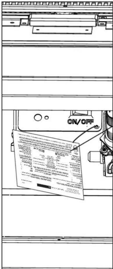
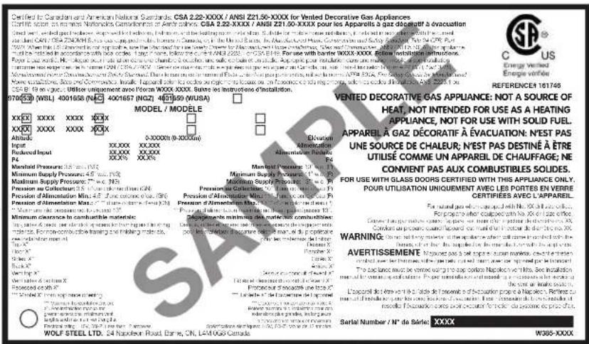
note:
The rating plate must remain with the appliance at all times. It must not be removed.
1.5 mobile home installation
This appliance must be installed in accordance with the manufacturer's instructions and the Manufactured Home Construction and Safety Standard, Title 24 CFR, Part 3280, in the United States or the Mobile Home Standard, CAN/CSA Z240 MH Series, in Canada. This appliance is only for use with the type(s) of gas indicated on the rating plate.
This mobile/manufactured home listed appliance comes factory equipped with a means to secure the appliance. Built in appliances are equipped with 1/4" (6.4mm) diameter holes located in the front left and right corners of the base. Use appropriate fasteners, inserted through the holes in the base to secure. For free standing products contact your local authorized dealer / distributor for the appropriate securing kit. For mobile home installations, the appliance must be fastened in place. It is recommended that the appliance be secured in all installations. Always turn off the pilot and the fuel supply at the source, prior to moving the mobile home. After moving the mobile home and prior to lighting the appliance, ensure that the logs are positioned correctly.
This appliance is certified to be installed in an aftermarket permanently located, manufactured (mobile) home, where not prohibited by local codes.
This appliance is only for use with the type of gas indicated on the rating plate. This appliance is not convertible for use with other gases, unless a certifi ed kit is used.
Conversion Kits
This appliance is fi eld convertible between Natural Gas (NG) and Propane (P). To convert from one gas to another, consult your Authorized dealer/distributor.
EN
general information
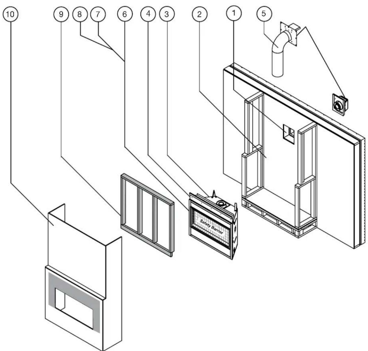
1.6 hardware list
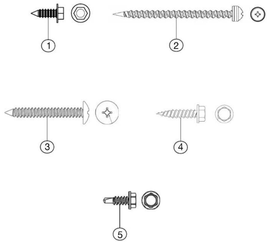
| Ref. Part # Description on Qty. | |||
| 1 | W570-0018 SCREW, #9-14x1/2” WILDRIL 1/4” HEX HD 25 | ||
| 2 | W570-0022 SCREW, #10 x 2-1/2” PAN HD (QUAD) 4 | ||
| 3 | W570-0026 SCREW, #10 x 1-1/2” TRUSS HD (QUAD) 4 | ||
| 4 | W570-0053 SCREW #8x3/4 HEX HD STH834B (BLACK ZINC) 4 | ||
| 5 | W570-0010 SCREW, #8 x 1/2IN HEX HD 2 | ||
note:
Only fasteners supplied with the appliance will be illustrated.
Top View
![C φA φB 11 3/8" [289mm] D* E](/content/2026/04/732729/images/80e7b02240d4980d0a3a19d58f4599142569095e6aeba78fe19c85f44e6908b9.jpg)
Front View
![SAFETY BARRIER 38 13/16" [985mm] 18 13/16"* [477mm] 8 11/16" [220mm]](/content/2026/04/732729/images/4a5e8930dd81549b31f2800676033eb8dbc0126eef0c269cbea98ecde4a49ec5.jpg)
Side View
![1/2" [13mm] 33 1/8" [841mm] 4 1/2" [115mm] 6 1/4" [158mm] 18 5/16" [465mm]](/content/2026/04/732729/images/203a7010ee92d21eb1e7eb03137da0c6d0afdb5c65840f8e2a374f024bd3df51.jpg)
| BLX42 BLX46 BLX56 | |||
| A | 4" (102mm) 4" (102mm) 5" (127mm) | ||
| B | 7" (178mm) 7" (178mm) 8" (203mm) | ||
| C | 18 3/4" (476mm) 22 3/4" (578mm) 32 3/4" (832mm) | ||
| D | 38 1/2" (978mm) 42 1/2" (1080mm) 52 1/2" (1334mm) | ||
| E | 42" (1067mm) 46" (1168mm) 56" (1422mm) | ||
*The finishing flange defines the perimeter of the fireplace opening; framing or finishing materials must NEVER encroach inside the finishing flange.
dimensions
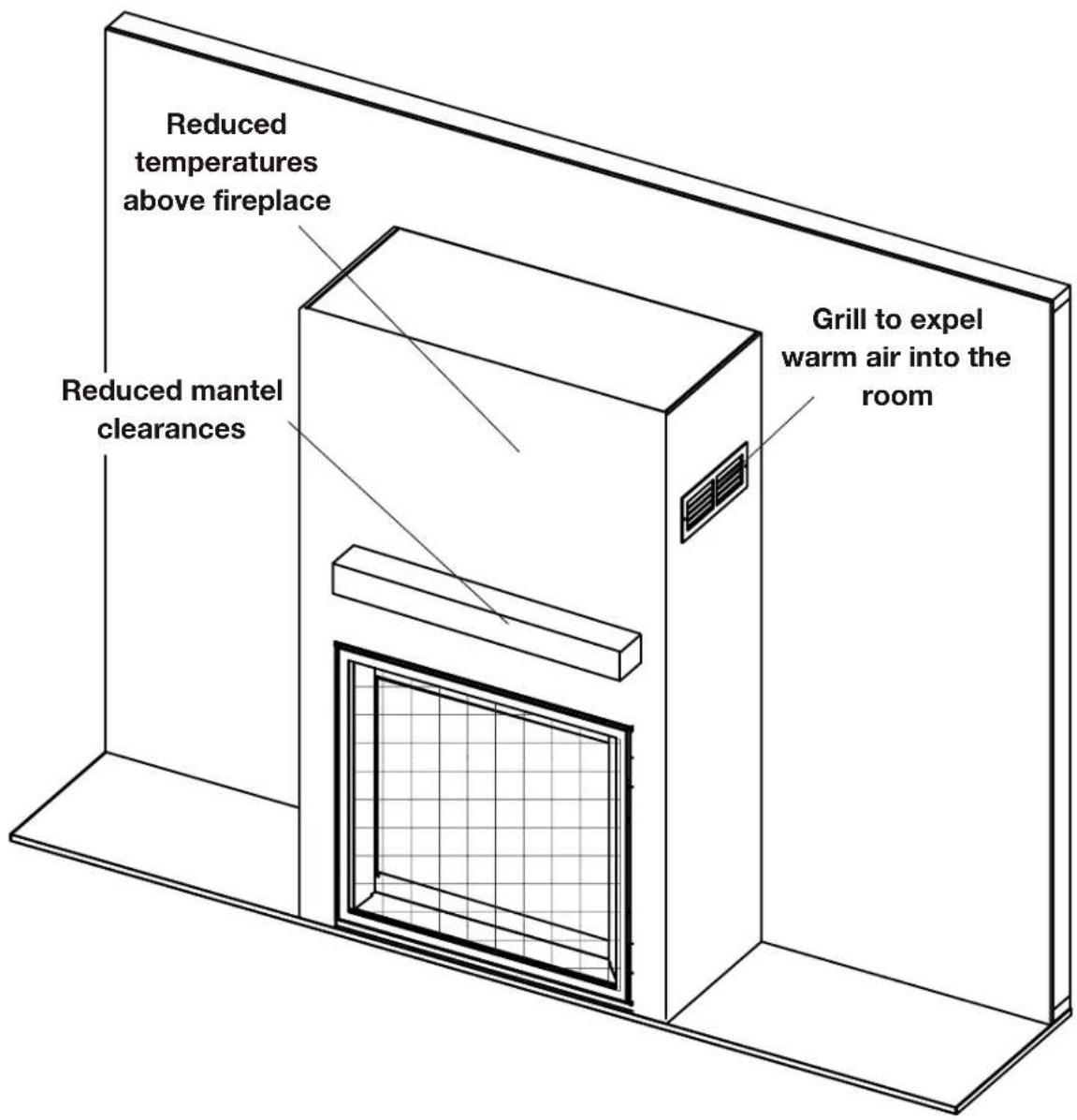
2.1 optional heat management system
The Universal Heat Management system is an optional gravity vent kit that allows you to manage the heat produced by the appliance at and around the appliance.
We recommend installing the Universal Heat Management system kit during the installation of the appliance BEFORE the gas is installed.
For more information, contact your local authorized dealer.
WARNING
- Risk of fire. Maintain specified air space clearances to vent pipe and appliance.
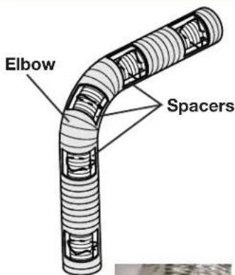
- The vent system must be supported every 3'(0.9m) for both vertical and horizontal runs. Use support ring assembly W010-0067 or equivalent non-combustible strapping to maintain the minimum clearance to combustibles for both vertical and horizontal runs. Spacers are attached to the inner pipe at predetermined intervals to maintain an even air gap to the outer pipe. This gap is required for safe operation. A spacer is required at the start, middle, and end of each elbow to ensure this gap is maintained. These spaces must not be removed.
note:
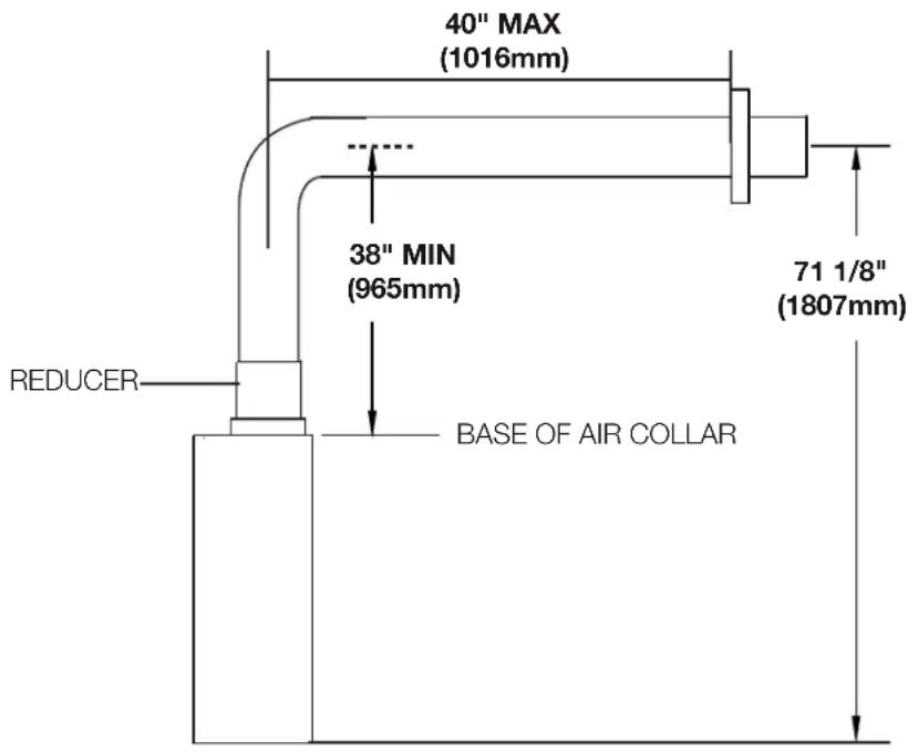
The minimum clearances from the top of the horizontal vent pipe to combustible materials may be reduced from 3" (76mm) to 1" (25mm) in those installations with a minimum 38" (965mm) vertical vent rise made immediately off the fireplace collar.
For safe and proper operation of the appliance, follow the venting instructions exactly. Deviation from the minimum vertical vent length can create difficulty in burner start-up and/or carboning. Under extreme vent configurations, allow several minutes (5-15) for the flame to stabilize after ignition. Although not a requirement, it is recommended for vent lengths that pass through unheated spaces (attics, garages, crawl spaces) be insulated with the insulation wrapped in a protective sleeve to minimize condensation. Provide a means for visually checking the vent connection to the appliance after the appliance is installed. Use a firestop, vent pipe shield or attic insulation shield when penetrating interior walls, floor or ceiling.
The vent terminal may be painted with a high temperature paint to match exterior colours. Use an outdoor paint suitable for 400°F (200°C). Application and performance of paint is the consumer's responsibility. Spot testing is recommended.
note:
If for any reason the vent air intake system is disassembled, re-install per the instructions provided for the initial installation.
This appliance must be installed with a continuous connection of exhaust and air intake vent pipes. Utilizing alternate constructions such as a chimney as part of the vent system is not permitted.
Connections made by means of an adaptor at the appliance, as well as the connection at the vent terminal must be sealed. RTV sealant may be used on both the inner exhaust and outer intake vent pipe joints of all other approved vent systems, except for the exhaust vent pipe connection to the appliance flue collar which must be sealed using the black high temperature sealant Mill Pac.
For all vent systems, it is strongly recommended for all installations but required when power venting the appliance, that the outer air intake joints are sealed using either high temperature silicone (RTV) or a suitable aluminum tape that covers each joint in the vent system entirely around its circumference. This will ensure the best performance in every application and avoids performance or condensation concerns that may occur in “tightly” constructed homes, particularly those in cold climates.
For optimum flame appearance and appliance performance, keep the vent length and number of elbows to a minimum.
The air terminal must remain unobstructed at all times. Examine the air terminal at least once a year to verify that it is unobstructed and undamaged.
Rigid and flexible venting systems must not be combined. Different venting manufacturer components must not be combined.
These vent kits allow for either horizontal or vertical venting of the appliance. The maximum allowable horizontal run is 20 feet (6.1m). The maximum allowable vertical vent length is 40 feet (12.2m). The maximum number of vent connections is two horizontally or three vertically (excluding the appliance and the air terminal connections) when using flexible venting.
venting requirements
Horizontal runs may have a 0" rise per foot or 0mm rise per meter however for optimum performance it is recommended that all horizontal runs have a minimum 1/4" rise per foot or 21mm rise per meter using flexible venting. For safe and proper operation of the appliance, follow the venting instructions exactly.
A terminal shall not terminate directly above a sidewalk or paved driveway which is located between two single family dwellings and serves both dwellings. Local codes or regulations may require different clearances.
Do not allow the inside liner to bunch up on horizontal or vertical runs and elbows. Keep it pulled tight. A 1¼" (31.8mm) air gap all around between the inner liner and outer liner is required for safe operation.
3.1 BLX42/46
The BLX42 and BLX46 models use a 4" (102mm) exhaust / 7" (178mm) air intake vent pipe system. Refer to the section applicable to your installation.
Use only Wolf Steel, Metal-Fab, BDM, Simpson Dura-Vent, or Selkirk Direct Temp venting components.
Minimum and maximum vent lengths, for both horizontal and vertical installations, clearances from vent pipes to combustibles and air terminal locations as set out in this manual apply to all vent systems and must be adhered to. For Metal-Fab, BDM, Simpson Dura-Vent, or Selkirk Direct Temp, follow the installation procedure provided with the venting components or on the website for your venting supplier.
A starter adaptor must be used with the following vent systems and may be purchased through Wolf Steel or from the corresponding supplier listed below:
| Venting System | Manufacturer | Starter Adapter Part Number | Supplier Website | |
| SureSeal Metal-Fab | 4DNA Wolf Steel www.mtlfab.com | |||
| Direct Vent Pro Simpson DuraVent W175-0053 Wolf Steel www.duravent.com | ||||
| Pro-Form BDM DVR6-STA7 BDM www.dalsinmfg.com | ||||
| Direct Temp | Selkirk | 4DT-AAN | Selkirk | www.selkirkcorp.com |
| Ventis | Olympia Chimney and Venting | VDV-NA04-47F | Olympia Chimney and Venting | www.olympiachimney.com |
When using Wolf Steel venting components, use only approved Wolf Steel rigid / flexible components with the following termination kits: wall terminal kit GD-222, GD-222R, ST47U or 1/12 to 7/12 pitch roof terminal kit GD-110, 8/12 to 12/12 roof terminal kit GD-111, flat roof terminal kit GD-112 or periscope kit GD-201 (for wall penetration below grade). With flexible venting, in conjunction with the various terminations, use either the 5 foot (1.5m) vent kit GD-220 or the 10 foot (3.1m) vent kit GD-330. For stoves only: wall terminal kit GD-175 (venting included).
3.2 BLX56
The BLX56 model uses a 5" (127mm) exhaust / 8" (203.2mm) air intake vent pipe system. Refer to the section applicable to your installation.
Use only Wolf Steel, Metal-Fab, BDM, Simpson Dura-Vent, or Selkirk Direct Temp venting components.
Minimum and maximum vent lengths, for both horizontal and vertical installations, clearances from vent pipes to combustibles and air terminal locations as set out in this manual apply to all vent systems and must be adhered to. For Metal-Fab, BDM, Simpson Dura-Vent, or Selkirk Direct Temp, follow the installation procedure provided with the venting components or on the website for your venting supplier.
A starter adaptor must be used with the following vent systems and may be purchased through Wolf Steel or from the corresponding supplier listed below:
| Venting System | Manufacturer | Starter Adapter Part Number | Supplier Website | |
| SureSeal Metal-Fab | 5DNA Wolf Steel www.mtlfab.com | |||
| Direct Vent Pro Simpson DuraVent W175-0170 Wolf Steel www.duravent.com | ||||
| Pro-Form BDM N/A | BDM www.dalsinmfg.com | |||
| Direct Temp | Selkirk | 5DT-AAN | Selkirk | www.selkirkcorp.com |
| Ventis | Olympia Chimney and Venting | VDV-NA05-58F | Olympia Chimney and Venting | www.olympiachimney.com |
When using Wolf Steel venting components, use only approved Wolf Steel rigid / flexible components with the following termination kits: wall terminal kit GD422-1, GD422R-2, ST58U-1 or 1/12 to 7/12 pitch roof terminal kit GD410, 8/12 to 12/12 roof terminal kit GD411, flat roof terminal kit GD412 or periscope kit GD401 (for wall penetration below grade). With flexible venting, in conjunction with the various terminations, use either the 5 foot (1.5m) vent kit GD420 or the 10 foot (3.1m) vent kit GD430.
venting requirements
3.3 typical venting installation
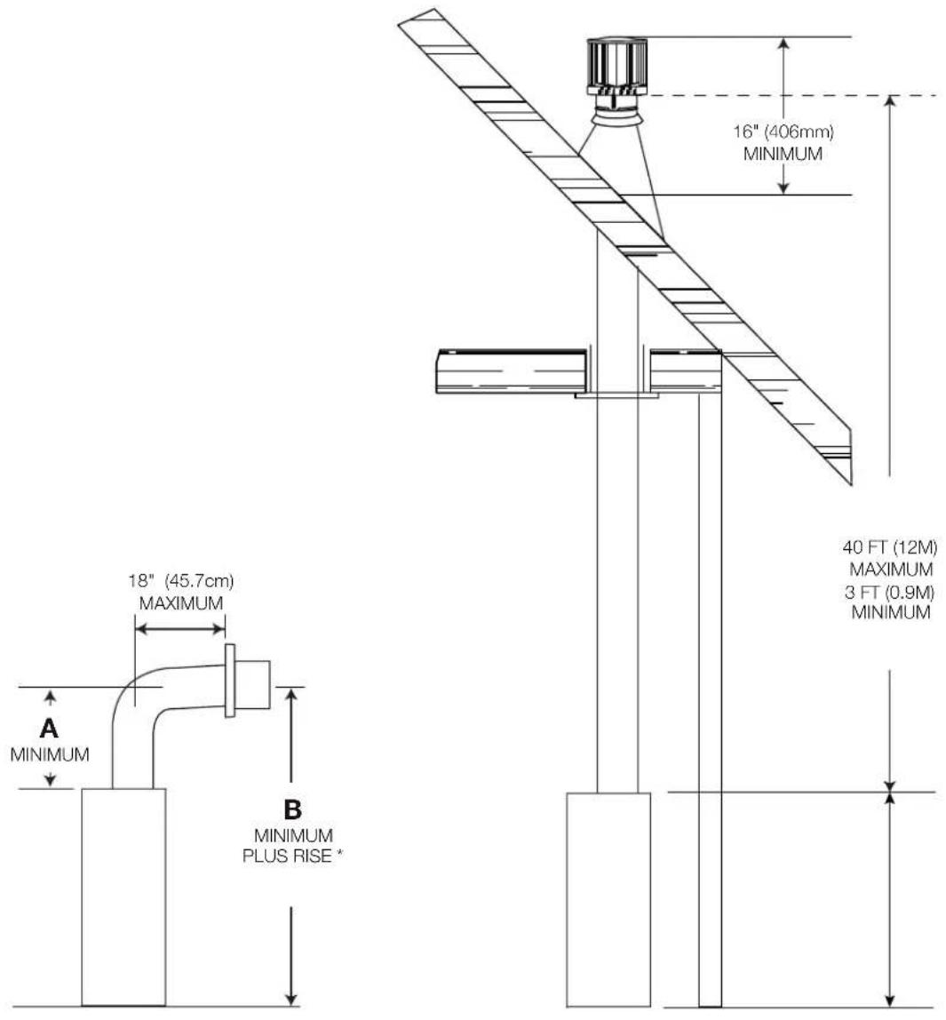
| Ref. BLX42 BLX46 BLX56 | |||
| A | 12 7/8” (327mm) 12 | 7/8” (327mm) 14 7/8” (378mm) | |
| B | 46” (1168mm) 46” | 1168mm) 48” (1219mm) | |
*See "venting requirements" and "venting installation" sections
3.4 special vent installation (periscope termination)
Use the periscope kit to locate the air termination above grade. The periscope must be installed so that when final grading is completed, the bottom air slot is located a minimum 12" (305mm) above grade. The maximum allowable vent length is 10' (3m) for a fireplace and 8' (2m) for a stove.
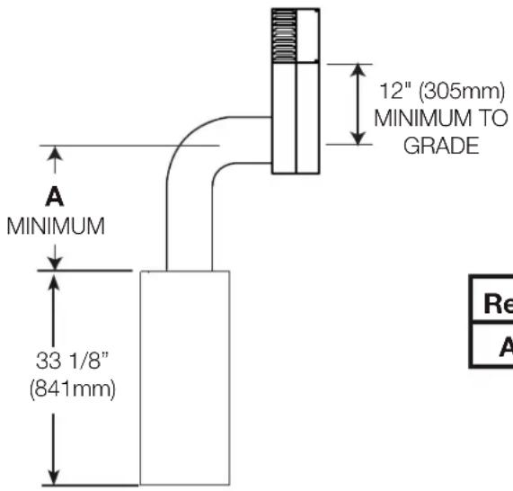
| Ref. | BLX42 BLX46 | BLX56 | |
| A | 30” (762mm) | 30” (762mm) | 32” (813mm) |
3.5 4/7" vent clearance to combustibles (BLX56)
If necessary, 5/8" venting can be reduced to 4/7" venting for the BLX56 models.
The minimum clearances around the horizontal vent pipe to the combustible material is 1" (25mm) in installations with a minimum of 38" (965mm) vertical rise made immediately off the appliance collar and where the vent has been reduced to a 4/7" from 5/8" at the appliance.
For 4"/7" (Use reducer kit A4758AK to transition from 5"/8" to 4"/7" venting)
When using Wolf Steel 4"7" venting components, use only approved Wolf Steel rigid / flexible components with the following termination kits: wall terminal kit GD-222, GD-222R, ST47U or 1/12 to 7/12 pitch roof terminal kit GD-110, 8/12 to 12/12 roof terminal kit GD-111, flat roof terminal kit GD-112 or periscope kit GD-201 (for wall penetration below grade). With flexible venting, in conjunction with the various terminations, use either the 5 foot (1.5m) vent kit GD-220 or the 10 foot (3.1m) vent kit GD-330. See 4/7" vent clearance to combustibles section for specific venting parameters.
venting requirements
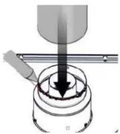
3.5.1 converting from 5/8" to 4/7" venting (BLX56)
1
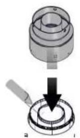
natural_image
Mechanical assembly diagram showing a cylindrical component being inserted into a ring, with no visible text or symbols.USE MILL PAC TO SEAL REDUCER TO THE APPLIANCE EXHAUST COLLARS.
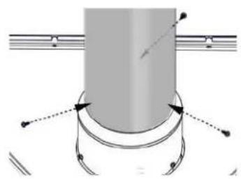
②
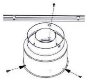
natural_image
Technical diagram of a mechanical component with no visible text or symbolsX3
③
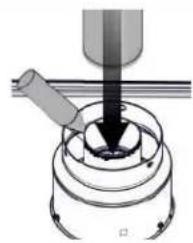
natural_image
Mechanical assembly diagram showing a tool interacting with a cylindrical component (no text or symbols visible)USE RED SILICONE TO SEAL REDUCER TO THE AIR INTAKE COLLARS.
④

natural_image
Mechanical assembly diagram showing a cylindrical component with concentric rings and mounting flanges (no text or symbols)X3
5
natural_image
Mechanical assembly diagram showing a cutting tool interacting with a cylindrical component (no text or symbols visible)USE RED SILICONE TO SEAL REDUCER TO THE AIR INTAKE COLLARS.
6
natural_image
Pure mechanical diagram showing a cylindrical component with curved arrows indicating motion or force direction (no text or symbols)X3
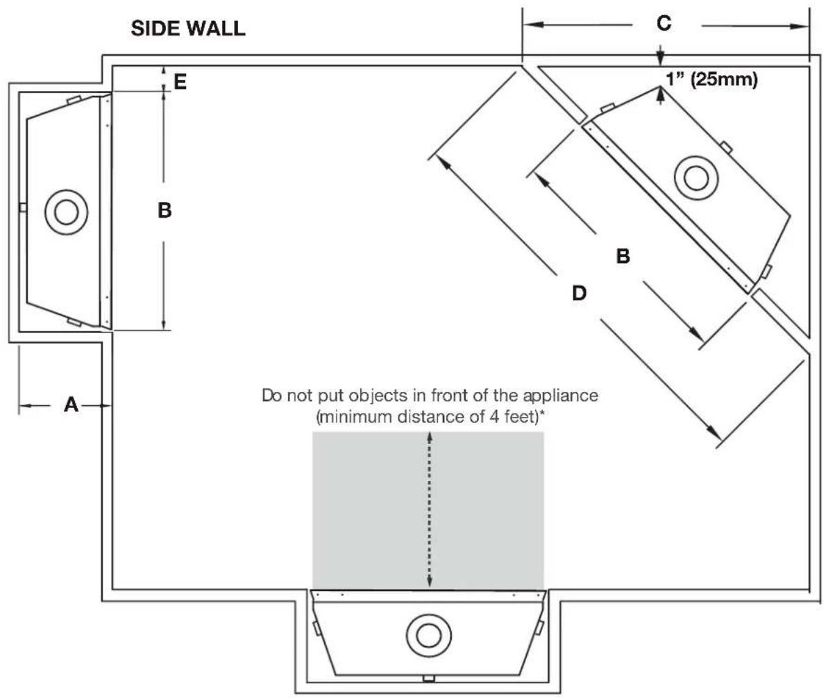
3.6 minimum air terminal location clearances
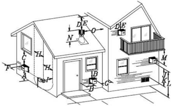
Covered balcony applications ††*
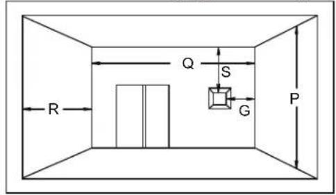
| Q_MIN = 3 feet (0.9m) | R_MAX = 2 × Q_ACTUAL | R_MAX ≤ 15 feet (4.6m) |
| INSTALLATIONS | note: | ||
| Wall terminals are for illustration purposes only. Size and shapes may vary. Wall terminal measurements taken from the exhaust outlet, not the mounting plate. | |||
| CANADA U.S.A. | |||
| A | 12" (30.5cm) 12" (30.5cm) Clearance above grade, veranda porch, deck or balcony. | ||
| B | 12" (30.5cm)^ | 9" (229mm) ^ | Clearance to windows or doors that open. |
| C | 12" (30.5cm)* 12" (30.5cm)* Clearance to permanently closed windows. | ||
| D | 18" (45.7cm)** | 18" (45.7cm)** | Vertical clearance to ventilated soffi ts located above the terminal within a horizontal distance of 2" (0.6m) from the center line of the terminal. |
| E | 12" (30.5cm)** 12" (30.5cm)** Clearance to unventilated soffi t. | ||
| F | 0" (0mm) 0" (0mm) Clearance to an outside corner wall. | ||
| G | 0" (0mm)*** 0" (0mm)*** | Clearance to an inside non-combustible corner wall or protruding non-combustible obstructions (chimney, etc.). | |
| 2" (51mm)*** | 2" (51mm)*** | Clearance to an inside combustible corner wall or protruding combustible obstructions (vent chase, etc.). | |
| H | 3'(0.9m) 3'(0.9m)**** | Clearance to each side of the center line extended above the meter / regulator assembly to a maximum vertical distance of 15' (4.6m). | |
| I | 3' (0.9m) 3' (0.9m)**** Clearance to a service regulator vent outlet. | ||
| J | 12" (30.5cm) | 9" (229mm) | Clearance to a non-mechanical air supply inlet to the building or a combustion air inlet to any other appliance. |
| K | 6' (1.8m) 3' (0.9m) † Clearance to a mechanical air supply inlet. | ||
| L | 7' (2.1m) ± | 7' (2.1m) **** | Clearance above a paved sidewalk or paved driveway located on public property. |
| M | 12" (30.5cm)†† | 12" (30.5cm)**** | Clearance under a veranda, porch, deck or overhang. |
| N | 16" (40.6cm) 16" (40.6cm) Clearance above the roof. | ||
| O | 2' (0.6m)†* | 2' (0.6m) † Clearance from an adjacent wall including neighbouring buildings. | |
| P | 8' (2.4m) 8' (2.4m) | Roof must be non-combustible without openings. | |
| Q | 3' (0.9m) 3' (0.9m) See chart for wider wall dimensions. | ||
| R | 6' (1.8m) 6' (1.8m) | See chart for deeper wall dimensions. The terminal shall not be installed on any wall that has an opening between the terminal and the open side of the structure. | |
| S | 12" (30.5cm) 12" (30.5cm) Clearance under a covered balcony | ||
The terminal shall not be located less than 6 feet under a window that opens on a horizontal plane in a structure with three walls and a roof.
• Recommended to prevent condensation on windows and thermal breakage
It is recommended to use a heat shield and to maximize the distance to vinyl clad soffits.
*** The periscope requires a minimum 18 inches clearance from an inside corner.
**** This is a recommended distance. For additional requirements, check local codes.
† 3 feet above if within 10 feet horizontally.
‡ A vent shall not terminate where it may cause hazardous frost or ice accumulations on adjacent property surfaces.
†† Permitted only if the veranda, porch, or deck is fully open on a minimum of two sides beneath the floor.
† Recommended to prevent recirculation of exhaust products. For additional requirements, check local codes.
Permitted only if the balcony is fully open on a minimum of one side.
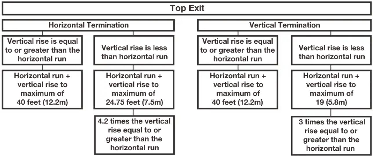
3.7 vent application flow chart
flowchart
graph TD
    A["Top Exit"] --> B["Horizontal Termination"]
    B --> C["Vertical rise is equal to or greater than the horizontal run"]
    C --> D["Horizontal run + vertical rise to maximum of 40 feet (12.2m)"]
    D --> E["Horizontal run + vertical rise to maximum of 24.75 feet (7.5m)"]
    E --> F["4.2 times the vertical rise equal to or greater than the horizontal run"]
    G["Vertical Termination"] --> H["Vertical rise is equal to or greater than the horizontal run"]
    H --> I["Horizontal run + vertical rise to maximum of 40 feet (12.2m)"]
    I --> J["3 times the vertical rise equal to or greater than the horizontal run"]
    K["Vertical Termination"] --> L["Vertical rise is equal to or greater than the horizontal run"]
    L --> M["Horizontal run + vertical rise to maximum of 19 (5.8m)"]
    M --> N["3 times the vertical rise equal to or greater than the horizontal run"]
3.8 definitions
For the following symbols used in the venting calculations and examples are:
- greater than
≥ - equal to or greater than
<- less than
≤ - equal to or less than
H_r - total of both horizontal vent lengths (Hr) and offsets (Ho) in feet
H_B - combined horizontal vent lengths in feet
H_0 - offset factor: .03 (total degrees of offset - 90°*) in feet
H_0 - offset factor: .03 (total degrees of offset - 135°*) in feet
V_T - combined vertical vent lengths in feet
3.9 elbow vent length values
| Feet | Inches | Millimeters |
| 1^ 0.03 | 0.5 | 12.7 |
| 15^ 0.45 | 6.0 | 152.4 |
| 30^ 0.9 | 11.0 | 279.4 |
| 45^ 1.35 | 16.0 | 406.4 |
| 90^* 2.7 | 32.0 | 812.8 |
* The first 90° offset has a zero value and is shown in the formula as - 90°
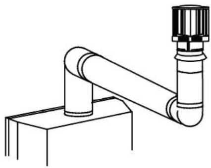
3.10 horizontal termination
$$ \left(\mathsf {H} _ {\mathrm{T}}\right) \leq \left(\mathsf {V} _ {\mathrm{T}}\right) $$
Simple venting configuration (only one 90° elbow)
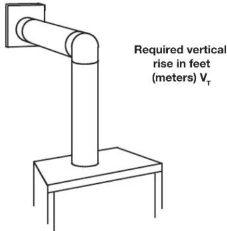
See graph to determine the required vertical rise V_T for the required horizontal run H_T .
line
| x | y | | ---- | ----- | | 0 | 40 | | 2.5 | 39 | | 5 | 38 | | 7.5 | 37 | | 10 | 36 | | 12.5 | 35 | | 15 | 34 | | 17.5 | 33 | | 20 | 32 |Horizontal vent run plus offset in feet (meters) H_T
The shaded area within the lines represents acceptable values for H_T and V_T
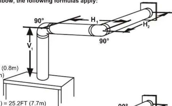
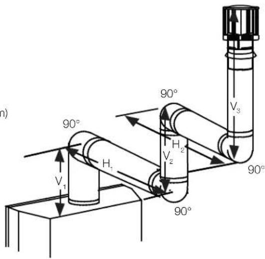
For vent configurations requiring more than one 90° elbow, the following formulas apply:
Formula 1: H_T ≤ V_T
Formula 2: H_+ + V_- ≤ 40 feet (12.2m)
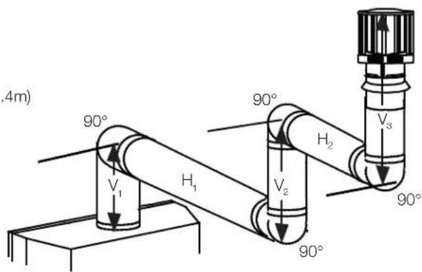
Example:
V_1 = 3ft(0.9m)
V_2=8 ft(2.4m)
V_T=V_1+V_2=3 ft(0.9m)+8 ft(2.4m)=11 ft(3.4m)
H_1=2.5 ft (0.8m)
H_2=2 ft (0.6m)
H_R = H_1 + H_2 = 2.5ft(0.8m) + 2ft(0.6m) = 4.5ft(1.4m)
H_0 = .03 (two 90^ elbows - 90^ ) = .03 ( 180^ - 90^ ) = 5.4 ft (1.7m)
H_r = H_R + H_O = 4.5 ft (1.4 m) + 5.4 ft (1.6 m) = 9.9 ft (3 m)
H_T + V_T = 9.9 ft (3m) + 11 ft (3.4m) = 20.9 ft (6.4m)
Formula 1: H_T ≤ V_T
9.9 ft (3m) < 11 ft (3.4m)
Formula 2: H_T + V_T ≤ 40 ft (12.2m)
20.9 ft (6.4m) < 40 ft (12.2m)
Since both formulas are met, this vent configuration is acceptable.
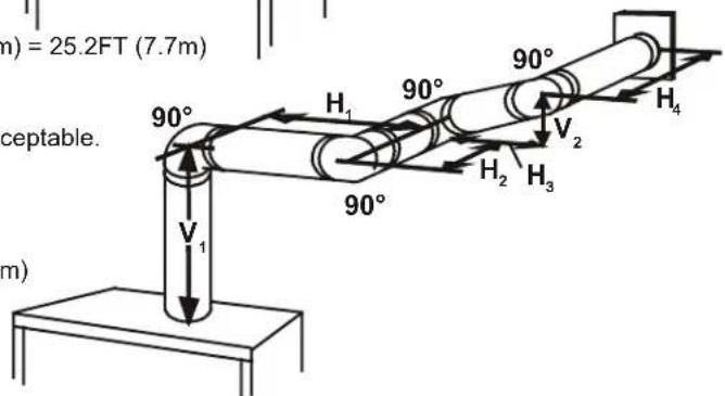
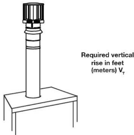
$$ \left(\mathbf {H} _ {\mathrm{T}}\right) > \left(\mathbf {V} _ {\mathrm{T}}\right) $$
Simple venting configuration (only one 90° elbow)
natural_image
Line drawing of a vertical cylindrical pipe mounted on a base, with no text or symbols present.See graph to determine the required vertical rise V_T for the required horizontal run H_T .
line
| BLX42/46 | BLX56 | | -------- | ----- | | 13 | 38 | | 15 | 38 |HORIZONTAL VENT RUN PLUS OFFSET IN FEET (METERS) H_T The shaded area within the lines represents acceptable values for H_T and V_T
For vent configurations requiring more than one 90° elbow, the following formulas apply:
Formula 1: HT ≤ 4.2 ~VT
H_0^2 = .03 (two 90^ elbows - 90^ ) = .03 ( 180^ - 90^ ) = 2.7FT (0.8m)
HT = HB + H_o = 8FT(2.4m) + 2.7FT(0.8m) = 10.7FT(3.3m)
H_T^+V_T^=10.7FT(3.3m)+6FT(1.8m)=16.7FT(5.1m)
Formula 1: H ≤ 4.2 V_T
$$ 4. 2 \mathrm{V} _ {\mathrm{T}} = 4. 2 \mathrm{FT} (1. 3 \mathrm{m}) \times 6 \mathrm{FT} (1. 8 \mathrm{m}) = 2 5. 2 \mathrm{FT} (7. 7 \mathrm{m}) $$
Formula 2: H T + VT ≤ 24.75 FT (7.5m)
$$ 1 6. 7 \mathrm{FT} (5. 1 \mathrm{m}) \leq 2 4. 7 5 \mathrm{FT} (7. 5 \mathrm{m}) $$
Since both formulas are met, this vent configuration is acceptable.
Example:
V_1=4FT(1.2m)
V_2=1.5FT(0.5m)
V = V1 + V_2 = 4FT(1.2m) + 1.5FT(0.5m) = 5.5FT(1.7m)
H_0 = .03 (four 90^ elbows - 90^ ) = .03 (360° - 90°) = 8.1 FT (2.5m)
HT = HR + H_o = 5.5FT(1.7m) + 8.1FT(2.5m) = 13.6FT(4.2m)
H_T^' + V_T^'' = 13.6 FT (4.2m) + 5.5 FT (1.7m) = 19.1 FT (5.8m)
Formula 1: H T ≤ 4.2 VT
$$ 4. 2 \mathrm{V} _ {\mathrm{T}} = 4. 2 \text {FT} (1. 3 \mathrm{m}) \times 5. 5 \text {FT} (1. 7 \mathrm{m}) = 2 3. 1 \text {FT} (7 \mathrm{m}) $$
$$ 1 3. 6 \mathrm{FT} (4. 2 \mathrm{m}) \leq 2 3. 1 \mathrm{FT} (7 \mathrm{m}) $$
Formula 2: H T + VT ≤ 24.75 FT (7.5m)
$$ 1 9. 1 \mathrm{FT} (5. 8 \mathrm{m}) \leq 2 4. 7 5 \mathrm{FT} (7. 5 \mathrm{m}) $$
Since both formulas are met, this vent configuration is acceptable.
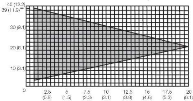
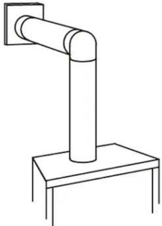
3.11 vertical termination
$$ \left(\mathrm{H} _ {\mathrm{T}}\right) \leq \left(\mathrm{V} _ {\mathrm{T}}\right) $$
Simple venting configurations.
See graph to determine the required vertical rise V_T for the required horizontal run H_T .
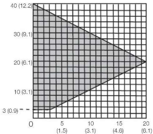
area
| X | Y | |---|---| | 0 | 40 (12.2) | | 5 | 30 (9.1) | | 10 | 20 (6.1) | | 15 | 10 (3.1) | | 20 | 3 (0.9) |Horizontal vent run plus offset in feet (meters) H_T The shaded area within the lines represents acceptable values for H_T and V_T
For vent configurations requiring one or more 90° elbows the following formulas apply:
Formula 1: H_1 ≤ V_1
Formula 2: H_T + V_T ≤ 40 feet (12.2m)
Example:
$$ V _ {1} = 5 \text { ft (1.5m) } $$
$$ V _ {o} = 6 \text { ft (1.8m) } $$
$$ V _ {3} = 1 0 \text { ft (3.1m) } $$
$$ V _ {T} = V _ {1} + V _ {2} + V _ {3} = 5 \text { ft (1.5m) } + 6 \text { ft (1.8m) } + 1 0 \text { ft (3.1m) } = 2 1 \text { ft (6.4m) } $$
$$ H _ {1} = 8 \text { ft } (2. 4 \mathrm{m}) $$
$$ H _ {2} = 2. 5 \text { ft (0.8m) } $$
$$ H _ {n} = H _ {1} + H _ {2} = 8 \text { ft (2.4m) } + 2. 5 \text { ft (0.8m) } = 1 0. 5 \text { ft (3.2m) } $$
$$ H _ {0} = . 0 3 \text {(four} 9 0 ^ {\circ} \text {elbows-} 9 0 ^ {\circ}) $$
$$ = . 0 3 (3 6 0 ^ {\circ} - 9 0 ^ {\circ}) = 8. 1 \text { ft } (2. 5 \mathrm{m}) $$
$$ H _ {T} = H _ {E} + H _ {O} = 1 0. 5 \text { ft (3.2m) } + 8. 1 \text { ft (2.5m) } = 1 8. 6 \text { ft (5.7m) } $$
$$ H _ {T} + V _ {T} = 1 8. 6 \text { ft (5.7m) } + 2 1 \text { ft (6.4m) } = 3 9. 6 \text { ft (12.1m) } $$
Formula 1: H ≤ V
$$ 1 8. 6 \mathrm{ft} (5. 7 \mathrm{m}) < 2 1 \mathrm{ft} (6. 4 \mathrm{m}) $$
Formula 2: H T + VT ≤ 40 ft (12.19m)
$$ 3 9. 6 \mathrm{ft} (1 2. 1 \mathrm{m}) < 4 0 \mathrm{ft} (1 2. 2 \mathrm{m}) $$
Since both formulas are met, this vent configuration is acceptable.
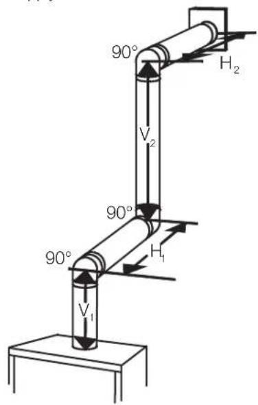
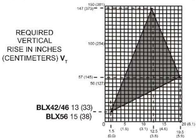
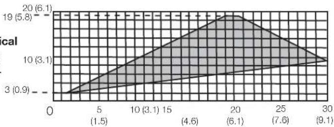
$$ \left(\mathrm{H} _ {\mathrm{T}}\right) > \left(\mathrm{V} _ {\mathrm{T}}\right) $$
Simple venting configurations.
See graph to determine the required vertical rise V_T for the required horizontal run H_T .
natural_image
Technical line drawing of a mechanical pipe assembly with a flanged support (no text or symbols)Required vertical rise in feet (meters) V_T
area
| x | cal | |---|---| | 0 | 3 (0.9) | | 5 | 10 (3.1) | | 10 | 19 (5.8) | | 15 | 20 (6.1) | | 20 | 19 (5.8) | | 25 | 10 (3.1) | | 30 | 3 (0.9) |Horizontal vent run plus offset in feet (meters) H_T The shaded area within the lines represents acceptable values for H_T and V_T
For vent configurations requiring more than two 90° elbows the following formulas apply:
Formula 1: H_T ≤ 3V_T
Formula 2: H_T + V_T ≤ 40 feet (12.2m)
Example:
V_1=2 ft(0.6m)
V_2=1 ft(0.3m)
V_3=1.5 ft (0.5m)
V_1 = V_1 + V_2 + V_3 = 2ft(0.6m) + 1ft(0.3m) + 1.5ft(0.5m) = 4.5ft(1.4m)
H_1=6 ft (1.8m)
H_2=2 ft(0.6m)
H_B=H_1+H_2=6 ft (1.8m)+2 ft (0.6m)=8 ft (2.4m)
H_0 = .03 (four 90° elbows - 90°)
$$ = . 0 3 (3 6 0 ^ {\circ} - 9 0 ^ {\circ}) = 8. 1 \text { ft } (2. 5 \mathrm{m}) $$
H_T = H_B + H_O = 8 ft (2.4m) + 8.1 ft (2.5m) = 16.1 ft (4.9m)
H_+ + V_+ = 16.1 ft (4.9m) + 4.5 ft (1.4m) = 20.6 ft (6.3m)
Formula 1: H T ≤ 3VT
$$ 3 \mathrm{V} _ {\tau} = 3 \text {ft} (0. 9 \mathrm{m}) \times 4. 5 \text {ft} (1. 4 \mathrm{m}) = 1 3. 5 \text {ft} (4. 1 \mathrm{m}) $$
$$ 1 6. 1 \mathrm{ft} (4. 9 \mathrm{m}) > 1 3. 5 \mathrm{ft} (4. 1 \mathrm{m}) $$
Since this formula is not met, this vent configuration is unacceptable.
Formula 2: H T + V T ≤ 40 ft (12.2m)
$$ 2 0. 6 \mathrm{ft} (6. 3 \mathrm{m}) < 4 0 \mathrm{ft} (1 2. 2 \mathrm{m}) _ {-} $$
Since only formula 2 is met, this vent configuration is unacceptable and a new appliance location or vent configuration will need to be established to satisfy both formulas.
3.12 vent shield installation
Required for minimum vent runs only.
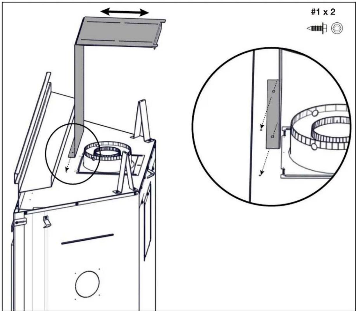
A. Form vent shield to a 90^ angle (as illustrated in installation step above).
B. Install the vent shield by securing it to top of appliance using 2 screws (supplied).
C. Adjust vent shield top to suit horizontal run.
note:
When using optional fi nishing accessories, the framing dimensions and fi nishing materials may differ from what is outlined in the section below; refer to the leafl et instructions supplied in the accessory kit for specific framing and fi nishing specifications.

WARNING
- Risk of fire!
- In order to avoid the possibility of exposed insulation or vapour barrier coming in contact with the appliance body, it is recommended that the walls of the appliance enclosure be “fi nished” (i.e. drywall / sheetrock), as you would fi nish any other outside wall of a home. This will ensure that clearance to combustibles is maintained within the cavity.
- Do not notch the framing around the appliance stand offs. Failure to maintain air space clearance may cause over heating and fire. Prevent contact with sagging or loose insulation or framing and other combustible materials. Block opening into the chase to prevent entry of blown-in insulation. Make sure insulation and other materials are secured.
- When constructing the enclosure, allow for fi nishing material thickness to maintain clearances. Framing or fi nishing material closer than the minimums listed must be constructed entirely of non-combustible materials. Materials consisting entirely of steel, iron, brick, tile, concrete, slate, glass or plasters, or any combination thereof are suitable. Materials that are reported as passing ASTM E136, standard test method for behaviour of materials in a vertical tube furnace at 1382°F (750°C) and UL763 shall be considered non-combustible materials.
- Minimum clearance to combustibles must be maintained or a serious fire hazard could result.
- The appliance requires a minimum enclosure height. Measure from the appliance base.
- If steel stud framing kits with cement board are provided, or specified in the installation instructions, they must be installed.
- If specified in the installation instruction, finishing must be done using a non-combustible board, ceramic tile, marble, etc. Do NOT use wood or drywall. Any fire rated drywall is not acceptable.
It is not necessary to install a hearth extension with this appliance.
4.1 minimum framing dimensions
note:
The minimum clearances from the top of the horizontal vent pipe to combustible materials may be reduced from 3" (76mm) to 1" (25mm) in those installations with a minimum 38" (965mm) vertical vent rise made immediately off the appliance collar.
| BLX42 BLX46 | BLX56 | ||
| A | 18 9/16" (471mm) | ||
| B | 42 1/2" (1080mm) 47 | 3/8" (1203mm) 56 | 1/2" (1435mm) |
| C | 41 1/8" (1045mm) 44" | (1118mm) 51" | (1295mm) |
| D | 58 1/4" (1480mm) 62 | 1/4" (1581mm) 72 | 1/4" (1835mm) |
| E | 6" (152mm) | ||
* This applies to all installation types.
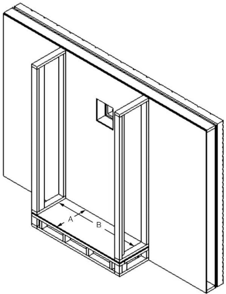
Before framing your appliance, determine vent requirements before deciding the final location of the appliance. After rough framing, place the appliance in its final position.
natural_image
Isometric line drawing of a two-panel wall assembly with labeled components A and B (no text or symbols beyond labels)| BLX42 BLX46 | BLX56 | ||
| A | 18 9/16” (471mm) | ||
| B | 42 1/2” (1080mm) | 47 3/8” (1203mm) | 56 1/2” (1435mm) |
WARNING
- Ensure to unpack all loose materials from inside the fi rebox prior to connecting the gas and electrical supply
- If your appliance is supplied with a remote, ensure the remote receiver is in the "OFF" position prior to connecting the gas and electrical supply to the appliance.
- For safe and proper operation of the appliance, follow the venting instructions exactly.
- The appliance exhaust flue collar must be sealed using Mill Pac. All exhaust and intake vent pipe joints must be sealed using red RTV high temp silicone sealant (W573-0002) (not supplied) or black high temp Mill Pac (W573-0007) (not supplied).
- If using pipe clamps to connect rigid vent components, a minimum of 3 screws must also be used to ensure the connection cannot slip off.
- Do not clamp the fl exible vent pipe.
- Risk of fire, explosion, or asphyxiation. Improper support of the entire venting system may allow vent to sag and separate. Use vent run supports and connect vent sections per installation instructions.
- Risk of fire, do not allow loose materials or insulation to touch the vent pipe. Remove insulation to allow for the installation of the attic shield and to maintain clearances to combustibles.
- Do not fi ll the space between the vent pipe and enclosure with any type of material. Do not pack insulation or combustibles between ceiling fi restops. Always maintain specifi ed clearances around venting and fi restop systems. Install wall shields and fi restops as specifi ed. Failure to keep insulation or other materials away from vent pipe may cause fi re.
- For gas stoves only: If the appliance is installed directly on carpeting, vinyl tile, or other combustible material other than wood flooring, the appliance shall be installed on a metal or wood panel extending the full width and depth, unless otherwise tested.
For optimum performance, it is recommended that all horizontal runs have a minimum of 1/4" (6mm) rise per foot using flexible venting. For safe and proper operation of the appliance, follow the venting instructions exactly.
venting installation
5.1 horizontal installation

WARNING
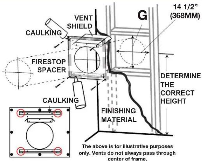
- The firestop assembly must be installed with the vent shield to the top.
- Terminals must not be recessed into a wall or siding more than the depth of the return flange of the mounting plate.
- The vent shield must be fixed in place by fastening the extended vent shield to the bend tabs using the supplied fasteners.
This application occurs when venting through an exterior wall. Having determined the correct height for the air terminal location, cut and frame a hole in the exterior wall, as illustrated, to accommodate the firestop assembly. Dry fit the firestop assembly before proceeding to ensure the brackets on the rear surface fit to the inside surface of the horizontal framing.
The vent shield must be installed to the full depth of the combustible wall. The length of the vent shield may be cut shorter for combustible walls less than 8 1/2" (216mm) thick.
note:
Bend the tabs for reduced side clearances or move the shield for reduced top clearances (dependent on specific appliance clearances). Do not fill the air space between the firestop spacer and the exterior wall with any type of insulating material (i.e. spray foam).
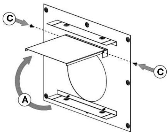
A. Fold the vent shield up so that it is perpendicular to the spacer plate.
B. Bend the tabs located on either side of the vent shield so that they are just shy of 90^ to the spacer plate.
C. On both sides of the firestop, fasten the (W570-0018) screws through the clearance holes in the bend tabs and thread into the holes in the vent shield.
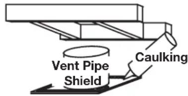
D. Apply a bead of caulking around the outer edge of the firestop assembly.
E. Screw the firestop onto the wall/framing, using 4 screws.
F. Once the vent pipe is installed in its final position, apply red RTV silicone (W573-0002) (not supplied) between the pipe and the firestop.
| BLX42 BL | X46 BLX5 | 6 | |
| G | 11 1/8" (282mm) | 13 | 1/8" (333mm) |
note:
Where the venting passes horizontally through a wall, you MUST use a Wolf Steel firestop for all rigid and flex vent systems. The gap between the outside diameter of the vent and the firestop MUST be completely sealed with high temperature RTV.
When using flex venting, use firestop assembly:
BLX42/46 models W010-3440 (not supplied).
BLX56 models W010-4479 (not supplied)
When using rigid venting, use firestop assembly:
BLX42/46 models 4DHFSN (not supplied).
BLX56 models 5DHFSN (not supplied).
5.2 vertical installation
This application occurs when venting through a roof. Installation kits for various roof pitches are available from your authorized dealer / distributor. See the “accessories” section to order specific kits required.
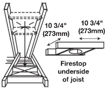
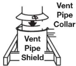
A. Determine the air terminal location, cut and frame a square opening, as illustrated, in the ceiling and the roof to provide the minimum 1" (25mm) clearance between the vent pipe and any combustible material. Try to center the vent pipe location midway between two joists to prevent having to cut them. Use a plumb bob to line up the center of the openings. A vent pipe shield will prevent any materials such as insulation, from filling up the 1" (25mm) air space around the pipe. Nail headers between the joist for extra support.
B. Apply a bead of caulking (not supplied) to the framework or to the Wolf Steel vent pipe shield plate or equivalent (in the case of a fi nished ceiling), and secure over the opening in the ceiling. A fi restop must be placed on the bottom of each framed opening in a roof or ceiling that the venting system passes through. Apply a bead of caulking all around and place a fi restop spacer over the vent shield to restrict cold air from being drawn into the room or around the fi replace. Ensure that both spacer and shield maintain the required clearance to combustibles. Once the vent pipe is installed in its fi nal position, apply red RTV silicone (W573-0002) (not supplied) between the pipe and the fi restop assembly.
C. In the attic, slide the vent pipe collar down to cover up the open end of the shield and tighten. This will prevent any materials, such as insulation, from filling up the 1" (25mm) air space around the pipe.
note:
When the venting passes vertically through a ceiling, you may use either Wolf Steel fi restops or the venting manufacturer's fi restops for rigid venting, provided they follow the required clearances listed in the appliance installation manual. For Wolf Steel flexible venting, you MUST use the Wolf Steel firestops listed below.
For 4"/7" appliances:
When using fl ex venting, use fi restop assembly W500-0292 (not supplied). When using rigid venting, use fi restop assembly 4DFS (not supplied).
For 5"/8" appliances:
When using fl ex venting, use fi restop assembly W500-0028 (not supplied). When using rigid venting, use fi restop assembly 5DFS (not supplied).
venting installation
5.3 using either flexible or rigid vent components

WARNING
- Do not allow the inner flex pipe to bunch up on horizontal or vertical runs and elbows. Keep it pulled tight.
- Spacers are attached to the inner flex pipe at predetermined intervals to maintain an even air gap to the outer flex pipe. This gap is required for safe operation. A spacer is required at the start, middle, and end of each elbow to ensure this gap is maintained. These spacers must not be removed.
For safe and proper operation of the appliance, follow the venting instructions exactly.
The vent system must be supported approximately every 3 feet (0.9m) for both vertical and horizontal runs. Use Wolf Steel Ltd. support ring assembly or equivalent noncombustible strapping to maintain the minimum clearance to combustibles for both vertical and horizontal runs.
All inner flex pipe and outer flex pipe joints may be sealed using high temperature red RTV silicone W573-0002 (not supplied) or the high temperature sealant W573-0007 Mill Pac (not supplied). However, the high temperature sealant W573-0007 Mill Pac (not supplied) must be used on the joint connecting the inner flex pipe and the exhaust flue collar.
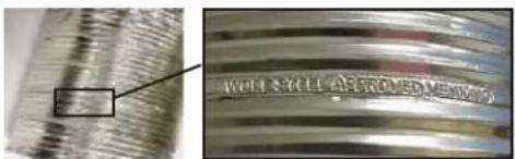
Use only approved flexible vent pipe kits marked:
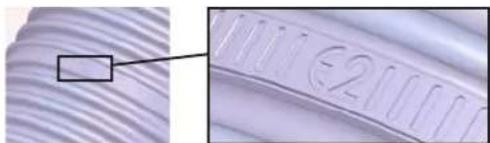
natural_image
Close-up of a textured surface with a highlighted rectangular region and a circular mark containing the number 2 (no readable text or symbols)"Wolf Steel Approved Venting" or "E2" as identified by the stamp only on the flex pipes.
When installing using rigid vent components, follow the manufacturer's installation and vent sealing requirements.
5.4 using flexible vent components
5.4.1 horizontal air terminal installation
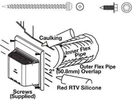
A. Stretch the inner fl ex pipe to the required length taking into account the additional length needed for the fi nished wall surface. Apply a heavy bead of the red RTV silicone (W573-0002) (not supplied) to the inner sleeve of the air terminal. Slip the vent pipe a minimum of 2" (50.8mm) over the inner sleeve of the air terminal and secure with a minimum of 3 screws.
B. Using the outer fl ex pipe, slide over the outer combustion air sleeve of the air terminal and secure with a minimum of 3 screws. Seal using red RTV silicone (W573-0002) (not supplied).
C. Insert the vent pipes through the fi restop maintaining the required clearance to combustibles. Holding the air terminal (lettering in an upright, readable position), secure to the exterior wall and make weather tight by sealing with caulking (not supplied).
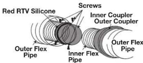
D. If more vent pipe needs to be used to reach the fi replace, couple them together, as illustrated. The vent system must be supported approximately every 3 feet (0.9m) for both vertical and horizontal runs. Use non-combustible strapping to maintain the minimum clearance to combustibles.
E. Stove Appliances Only: From inside the house, using Red RTV Silicone (W573-0002) (not supplied), seal between the vent pipe and the fi restop. Then slide the black trim collar over the vent pipe up to the fi restop.
The air terminal mounting plate may be recessed into the exterior wall or siding no greater than the depth of its return fl ange.
2 X4 #1 X6
5.4.2 vertical air terminal installation

WARNING
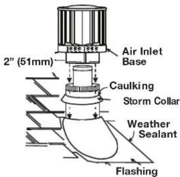
- Maintain a minimum 2" (51mm) space between the air inlet base and the storm collar.
note:
Fastening hardware provided with appropriate roof terminal and liner kits.
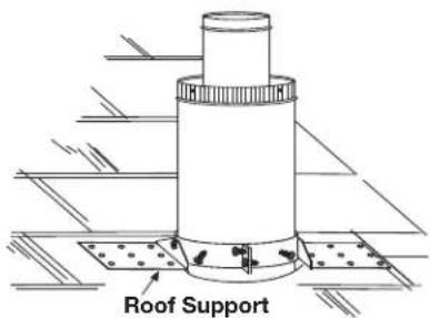
A. Fasten the roof support to the roof using 6 screws. The roof support is optional. In this case, the venting is to be adequately supported using either an alternate method suitable to the authority having jurisdiction or the optional roof support.
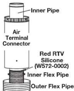
B. Stretch the inner fl ex pipe to the required length. Slip the inner fl ex pipe a minimum of 2" (51mm) over the inner pipe of the air terminal connector and secure with a minimum of three screws, when 4/7, 5/8 and 3/5 venting is used and a minimum of six screws when using 8/10 or 8/11 venting. Seal using a heavy bead of red RTV silicone sealant (W573-0002) (not supplied).
C. Repeat using the outer fl ex pipe, using a heavy bead of red RTV silicone sealant (W573-0002) (not supplied) and a minimum of three screws, when 4/7, 5/8 and 3/5 venting is used and a minimum of six screws when using 8/10 or 8/11 venting.
D. Thread the air terminal connector / vent pipe assembly down through the roof. The air terminal must be positioned vertically and plumb. Attach the air terminal connector to the roof support, ensuring that the top of the air terminal is 16" (40.6cm) above the highest point that it penetrates the roof.
E. Remove nails from the shingles, above and to the sides of the air terminal connector. Place the fl ashing over the air terminal connector leaving a min. 3/4" (19mm) of the air terminal connector showing above the top of the fl ashing. Slide the fl ashing underneath the sides and upper edge of the shingles. Ensure that the air terminal connector is properly centered within the fl ashing, giving a 3/4" (19mm) margin all around. Fasten to the roof. Do not nail through the lower portion of the fl ashing. Make weather-tight by sealing with caulking. Where possible, cover the sides and top edges of the fl ashing with roofing material.
F. Aligning the seams of the terminal and air terminal connector, place the terminal over the air terminal connector making sure the vent pipe goes into the hole in the terminal. Secure with a minimum of three screws, when 4/7, 5/8 and 3/5 venting is used and a minimum of six screws when using 8/10 or 8/11 venting.
G. Apply a heavy bead of weatherproof caulking 2" (51mm) above the fl ashing. Install the storm collar around the air terminal and slide down to the caulking. Tighten to ensure that a weather-tight seal between the air terminal and the collar is achieved.
H. If more vent pipe needs to be used to reach the appliance, see "horizontal air terminal installation" section.
5.4.3 appliance vent connection
A. Install the inner fl ex pipe to the appliance. Secure with a minimum of three screws when installing 3"/5", 4"/7" or 5"/8" venting, or six screws when installing 8"/10" or 8"/11" venting. Seal the joint and screw holes using Mill Pac sealant (W573-0007) (not supplied).
B. Install the outer fl ex pipe to the appliance. Secure with a minimum of three screws when installing 3"/5", 4"/7" or 5"/8" venting, or six screws when installing 8"/10" or 8"/11" venting. Seal the joints using high temperature red RTV silicone (W573-0002) (not supplied).
EN
venting installation
5.5 using rigid vent components
5.5.1 horizontal air terminal installation
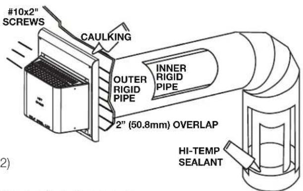
A. Move the appliance into position. Measure the vent length required between terminal and appliance taking into account the additional length needed for the finished wall surface and any 2" (50.8mm) overlaps between venting components.
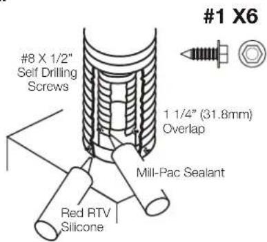
B. Apply a heavy bead of Mill Pac sealant (W573-0007) (not supplied) to the outer edge of the inner collar of the appliance. Attach the first inner rigid pipe component and secure using a minimum of three screws. Repeat using the outer rigid pipe. Seal using Red RTV Silicone (W573-0002) (not supplied).
C. Insert the vent pipes through the fi restop maintaining the required clearance to combustibles. Apply a heavy bead of Red RTV Silicone (W573-0002) (not supplied) to both the inner sleeve and outer sleeve of the air terminal. Slide the terminal sleeves into the rigid pipes a minimum of 1 1/4". Holding the air terminal (lettering in an upright, readable position), secure to the exterior wall and make weather tight by sealing with caulking (not supplied).
The air terminal mounting plate may be recessed into the exterior wall or siding no greater than the depth of the return fl ange.
5.5.2 vertical air terminal installation

WARNING
- Maintain a minimum 2" (51mm) space between the air inlet base and the storm collar.
note:
Fastening hardware provided with appropriate roof terminal and liner kits.
Before attaching elbows to the collars on the back of the appliance, 1 1/2" (38.1mm) will need to be trimmed off the 4" (101.6mm) collar.
REAR VENT APPLICATIONS ONLY: Attach 4" (101.6mm) and 7" (177.8mm) elbows to the appliance. Secure with 3 screws and seal the joints and screw heads using high temperature sealant. Proceed to step A below.
TOP AND REAR VENT APPLICATIONS:
A. Move the appliance into position.
B. Fasten the roof support to the roof using the screws provided. The roof support is optional. In this case the venting is to be adequately supported using either an alternate method suitable to the authority having jurisdiction or the optional roof support.
C. Apply high temperature sealant W573-0007 (not supplied) to the outer edge of the inner sleeve of the air terminal. Slip the inner coupler a minimum of 2" (51mm) over the sleeve and secure using 3 screws.
D. Apply high temperature sealant W573-0002 (not supplied) to the outer edge of the of the outside sleeve of the air terminal connector. Slip the outer coupler over the sleeve and secure as before. Trim the outer coupler even with the inner coupler end.
E. Thread the air terminal connector / vent pipe assembly down through the roof support and attach, ensuring that a minimum 16" (40.6cm) of air terminal connector will penetrate the roof when fastened. If the attic space is tight, we recommend threading the Wolf Steel vent pipe collar or equivalent loosely onto the air terminal connector / vent pipe assembly as it is passed through the attic. The air terminal connector must be positioned vertically and plumb.
F. Remove nails from the shingles, above and to the sides of the air terminal connector. Place the flashing over the air terminal connector and slide it underneath the sides and upper edge of the shingles. Ensure that the air terminal connector is properly centered within the flashing, giving a 3/4"

(19.1mm) margin all around. Fasten to the roof. Do NOT nail through the lower portion of the flashing. Make weather-tight by sealing with caulking. Where possible, cover the sides and top edges of the flashing with roofing material.
G. Apply a heavy bead of waterproof caulking 2" (51mm) above the flashing. Install the storm collar around the air terminal and slide down to the caulking. Tighten to ensure that a weather-tight seal between the air terminal connector and the collar is achieved.
H. Continue adding rigid venting sections, sealing and securing as above. Attach the inner collapsed telescopic sleeve to the last section of rigid piping. Secure with screws and seal. Repeat using the outer telescopic sleeve.
I. Run a bead of high temperature sealant W573-0007 (not supplied) around the outside of the inner elbow for rear vent applications or the inner collar for top vent applications. Pull the telescopic sleeve a minimum of 2" (51mm) onto the elbow. Secure with three screws. Repeat with the outer telescopic sleeve.
TOP VENT APPLICATIONS ONLY:
K. In the attic, slide the vent pipe collar down to cover up the open end of the shield and tighten. This will prevent any materials, such as insulation, from filling up the 1" (25mm) air space around the pipe.
venting installation
5.5.3 restricting vertical vents

WARNING
- Turn off gas and electrical supply before servicing the appliance.
- Appliance may be hot, do not service until appliance is cool.
- For safe and proper operation of the appliance, follow the venting instruction exactly.
- To avoid danger of suffocation, keep the packaging bag away from babies and children. Do not use in cribs, beds, carriages or play pens. This bag is not a toy. Knot before throwing away.
Vertical installations may display a very active flame. If this appearance is not desirable, the exhaust outlet may be restricted with a Wolf Steel approved restrictor kit. This kit is not recommended for short vertical vent runs.
Depending on the model and/or year of your appliance, mounting holes may not exist.
A. If mounting holes exist, remove the screws from the firebox top, align the restrictor plate as illustrated and secure.
B. If mounting holes do not exist, align the restrictor plate as illustrated and secure using the two #8x1/2 hex head sheet metal screws supplied.
C. Ensure the plate will pivot at the slot up into the exhaust outlet.
D. Depending on the amount of restriction desired, the restrictor plate can be left flat for most restriction or bent up for varying degrees of restriction.
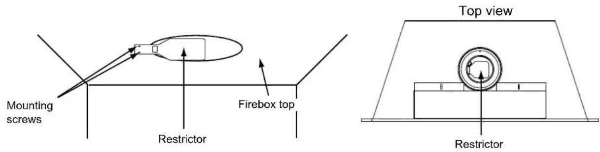
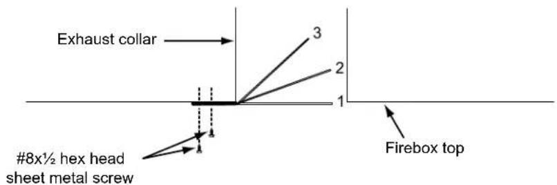
- Most restriction
- Moderate restriction
- Least restriction
5.6 vertical through existing chimney (BLX42/46)

WARNING
- Risk of fi re.
- Co-axial to co-linear venting confi gurations must only be used in a non-combustible chimney or enclosure. Installation in a combustible enclosure could result in a fi re.
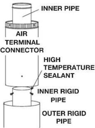
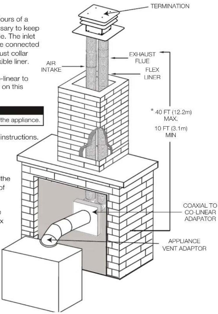
This appliance is designed to be attached to a 3" (76.2mm) co-linear aluminum fl ex vent system running the full length of a masonry chimney.
The fl ex liners accommodate any contours of a masonry chimney, however, it is necessary to keep the fl exible liners as straight as possible. The inlet air collar of the termination cap must be connected to the air intake fl ex liner and the exhaust collar must be connected to the exhaust fl exible liner.
Both Simpson Duravent and Selkirk co-linear to co-axial adaptors have been approved on this appliance
note:
A vent adaptor will be required directly off the appliance.
Follow vent manufacturer's installation instructions.
Different manufacturer's venting components must not be combined. Once the preferred manufacturer's appliance adaptor has been attached, the remainder of the system must be that of the same manufacturer.
The only exception to this rule is to use Wolf Steel's approved 3" (76.2mm) fl ex liner and co-linear termination.
* Measured from appliance fl ue collar to termination fl ue collar
6e0ntelecitristallinformation
6.1 hard wiring connection
It is necessary to hard wire this appliance.
This appliance must be electrically connected and grounded in accordance with local codes. In the absence of local codes, use the current CSA C22.1 Canadian Electrical Code in Canada or the ANSI/NFPA 70-1996 National Electrical Code in the United States.
6.2 receptacle wiring diagram
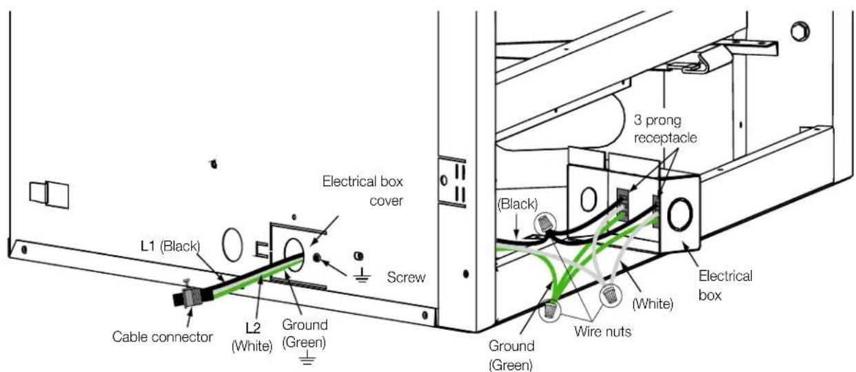
6.3 electronic wiring diagram

WARNING
- Do not use this appliance if any part has been under water. Call a qualified service technician immediately to have the appliance inspected for damage to the electrical circuit.
- Risk of electrical shock or explosion. Do not wire 110V to the valve or to the appliance wall switch. Incorrect wiring will damage controls.
- All wiring should be done by a qualified electrician and shall be in compliance with local codes. In the absence of local codes, use the current CSA22.1 Canadian Electric Code in Canada or the current National Electric Code ANSI/NFPA NO. 70 in the United States.
- Always light the pilot whether for the first time or if the gas supply has run out, with the glass door opened or removed.
6.4 initializing the transmitter / battery holder for the first time

WARNING
- Ensure the gas and electrical power to the appliance is turned off.
- Appliance may be hot, do not service until the appliance has cooled.
A. Install the 4 AA batteries into the Proflame 2 battery holder, note the polarity of the batteries and insert as indicated on the cover (+/-).
B. Ensure the 3 position slider switch is switched to the "REMOTE" position (middle position).
C. Press the reset/programming button, use a small object such as a paper clip in order to reach the button marked PRG, as shown in the illustration below.
D. The battery holder will beep 3 times to indicate that it's ready to synchronize with the transmitter.
E. Install the 3 AAA batteries into the transmitter, as shown in the photograph below, then press the ON button. The battery holder will beep 4 times to indicate that the transmitter's command is accepted.
note:
The initializing process must be completed within 10 seconds of pressing the reset/programming button (PRG).

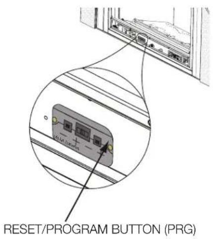
6.5 wiring diagram

WARNING
- Do not wire 110 volts to the valve or wall switch.
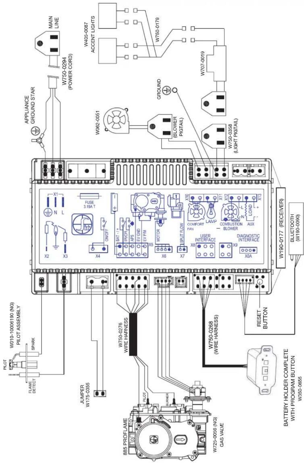

WARNING
- Risk of fi re, explosion, or asphyxiation. Ensure there are no ignition sources such as sparks or open fl ames.
- Support gas control when attaching gas supply pipe to prevent damaging gas line.
- Always light the pilot whether for the first time or if the gas supply has run out with the glass door opened or removed. Purging of the gas supply line should be performed by a qualified service technician. Ensure that a continuous gas flow is at the burner before closing the door. Ensure adequate ventilation. For gas and electrical locations, see "dimensions" section.
• All gas connections must be contained within the appliance when complete (gas fireplaces only). - High pressure will damage valve. Disconnect gas supply piping before testing gas line at test pressures above 1/2 PSIG.
- Valve settings have been factory set, do not change.
Installation and servicing to be done by a qualified installer.
- Move the appliance into position and secure.
- If equipped with a fl ex connector, the appliance is designed to accept a 1/2" (13mm) gas supply. Without the connector, it is designed to accept a 3/8" (9.5mm) gas supply. The appliance is equipped with a manual shut off valve to turn off the gas supply to the appliance.
- Connect the gas supply in accordance to local codes. In the absence of local codes, install to the current CAN/CSA-B149.1 Installation Code in Canada or to the current National Fuel Gas Code, ANSI Z223.1 / NFPA 54 in the United States.
- When fl exing any gas line, support the gas valve so that the lines are not bent or kinked.
- The gas line fl ex-connector should be installed to provide sufficient movement for shifting the burner assembly on its side to aid with servicing components.
- Check for gas leaks by brushing on a soap and water solution. Do not use open fl ame.
After installing the electrical wiring and gas lines, ensure to test the appliance before finishing the framing and finishing the appliance.

WARNING
- If you do not follow these instructions exactly, a fire or explosion may result causing property damage, personal injury, or loss of life.
- If applicable, always light the pilot whether for the first time or if the gas supply has run out with the glass door opened or removed.
Ensure that a continuous gas flow is at the burner before installing the door. When lit for the first time, the appliance will emit an odor for a few hours. This is a normal temporary condition caused by the "burn-in" of paints and lubricants used in the manufacturing process and will not occur again. After extended periods of non-operation, such as, following a vacation or warm weather season, the appliance may emit a slight odor for a few hours. This is caused by dust particules in the heat exchanger burning off. In both cases, open a window to sufficiently ventilate the room.
FOR YOUR SAFETY READ BEFORE LIGHTING
- Do not turn on if children or other at risk individuals are near the appliance.
- This appliance is equipped with an ignition device which automatically lights the pilot. Do not try to light the pilot by hand.
- Before operating, smell all around the appliance area for gas and next to the floor because some gas is heavier than air and will settle on the floor.
- Do not use this appliance if any part has been under water. Immediately call a qualified service technician to inspect the appliance and replace any part of the control system and any gas control which has been underwater.
WHAT TO DO IF YOU SMELL GAS
- Turn off all gas to the appliance.
- Open windows.
- Do not try to light any appliance.
-
Do not touch any electric switch; do not use any phone in your building
-
Immediately call your gas supplier from a neighbour's phone. Follow the gas supplier's instructions.
- If you cannot reach your gas supplier, call the fire department.
LIGHTING INSTRUCTIONS
note:
This appliance is equipped with an ignition device which automatically lights the pilot. Do not try to light the pilot by hand.
A. Stop! Read the above safety information on this label.
B. Remove batteries from the transmitter and set thermostat to lowest setting, if equipped.
C. Turn off all electrical power to the appliance.
D. Open the glass door, if equipped.
E. Turn the manual shut-off valve clockwise to the "OFF" position. (Shut-off valve is located on the fl ex connector).
F. Wait fi ve (5) minutes to clear out any gas. If you smell gas including near the floor, STOP! Follow the instructions above in the "WHAT TO DO IF YOU SMELL GAS" section. If you don't smell gas; close the glass door and go to the next step.
G. Turn the manual shut-off valve counter clockwise to the "ON" position.
H. Turn on all electrical power to the appliance and re-install the batteries into the transmitter. Set thermostat to desired setting, if equipped.
I. Turn on the remote wall switch to the appliance.
J. If the appliance will not operate, follow instructions "TO TURN OFF GAS" and call your service technician or gas supplier.
TO TURN OFF GAS
A. Set thermostat to lowest setting, if equipped.
B. Turn off the remote wall switch to the appliance.
C. Turn off all electric power to the appliance if service is to be performed.
D. Turn manual shutoff valve clockwise to the "OFF" positon. Do not force.
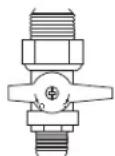
MANUAL SHUT-OFF
(SHOWN IN OFF POSITION)
natural_image
Technical line drawing of a mechanical assembly (no text or symbols visible)8.1 pilot on demand
This appliance is equipped with an “On Demand” intermittent pilot ignition system (IPI) which also includes a continuous pilot ignition (CPI) mode with an integrated seven day timer. This system minimizes your appliance’s carbon footprint as well as reducing its annual fuel consumption and operating costs.
In IPI mode, the pilot will ignite prior to the main burner, when the appliance is turned on using a switch, remote or from a call for heat with the thermostat (if equipped). Once the appliance is turned off (or the call for heat is satisfied), the main burner and pilot flame will shut down.
The continuous (CPI) mode is intended to enhance the performance of the appliance during the startup phase in colder climates and extreme weather by keeping the system warm when the main burner is not in use. However, the timer feature provides the convenience that the appliance automatically switches off the pilot when the appliance has not been used for seven days to save unnecessary fuel consumption.
When the CPI function is turned on, the pilot will remain on after the main burner is turned off. A timer will then begin the countdown for approximately seven days before shutting off the pilot if the appliance is not used. This countdown will reset anytime the appliance main burner is used. Therefore, if the appliance is regularly used day to day, the pilot will remain on. However, this system does not require the user to remember to turn the pilot off as summer approaches and avoids unnecessary fuel consumption while still readily turned back on when the cold weather returns.
Your appliance may be equipped with an ACS or remote control device (Fig. 1) which enables you to select IPI or CPI modes.

natural_image
Black remote control device with a small display and control buttons (no visible text or symbols)(Fig. 1)
If your appliance is equipped with an ACS switch, it has the option to change modes:
Fig. 2: Flipping the switch ON turns on the continuous pilot with timer and flipping the switch OFF turns on the intermittent pilot ignition.
Fig. 3: If installed with the blue wire facing up, flipping the switch UP turns on the continuous pilot with timer and fl ipping the switch DOWN turns on the intermittent pilot ignition. If installed with the white wire facing up, the opposite is true.
If your appliance is equipped with a remote control device capable of selecting IPI / CPI modes, refer to remote operating instructions.
In order to start your pilot, turning the main burner on with the switch, remote or thermostat and then turning it off will reactivate the continuous pilot mode and reset the seven day timer.
For further information, refer to www.napoleon.com/pilotondemand
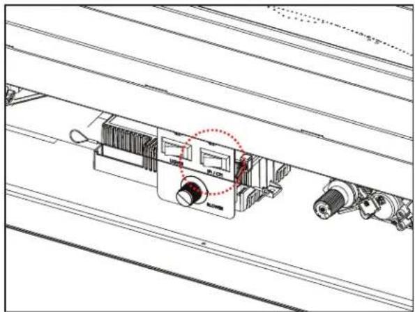
(Fig. 2) (Fig. 3)
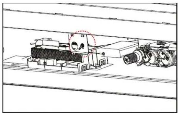
natural_image
Technical line drawing of a mechanical assembly with rollers and a central component (no text or symbols)Girishifrishming
9.1 nailing tab installation
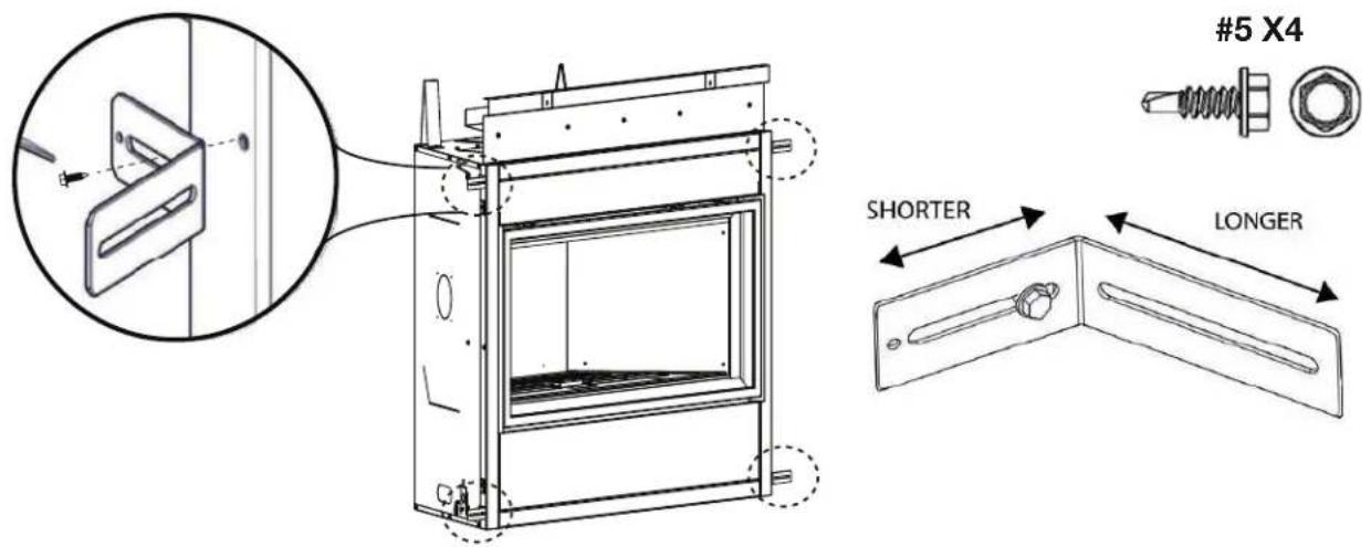
Use one screw to secure the short side of the nailing bracket to the appliance. Repeat for 3 other locations.
note:
Adjust bracket to suit your desired finishing material.
Bend tabs 180° upwards and secure to header.
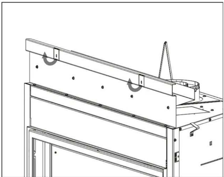
natural_image
Technical line drawing of a mechanical assembly with no visible text or symbolsnote:
See “venting requirements”, “venting installation”, “electrical information” and “gas installation” sections prior to finish framing.
9.2 flush

WARNING
- Do not build into this area - it must be left clear to provide adequate clearance for the vent in this 14" (356mm) wide area centered along the front of the appliance. The appliance should be in its final location before framing.
![CEILING G MINIMUM FROM BASE OF APPLIANCE 14" [35.6cm] MIN COMBUSTIBLE HEADER F B A DRYWALL](/content/2026/04/732729/images/7974472c072f7d46c21599e3a6e2f2b0b50958dc4f18098a949f0b67826e0268.jpg)
| BLX42 | BLX46 | BLX56 | |
| B | 42 1/2" (1080mm) | 47 3/8" (1203mm) | 56 1/2" (1435mm) |
| F | 39 3/8" (1000mm) | ||
| A | 18 9/16" (471mm) | ||
| G | 56" (1422mm) | 60" (1524mm) | |
9.3 recessed
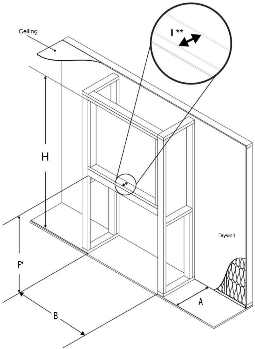
* Allow for finished floor and hearth thickness when setting these dimensions.
** 2" x 4" frame can be "backed" with 3/4" ply to support TV mounting hardware.
| BLX42 BLX46 | BLX56 | ||
| F | 39 3/8" (1000mm) | ||
| A | 18 9/16" (471mm) | ||
| B | 42 1/2" (1080mm) | 47 3/8" (1203mm) 56 | 1/2" (1435mm) |
| H | 84" (2130mm) | ||
| I | 3 1/2" (89mm) | ||
9.4 minimum clearance to combustible enclosures
3" [76mm] minimum all sides for vertical venting.
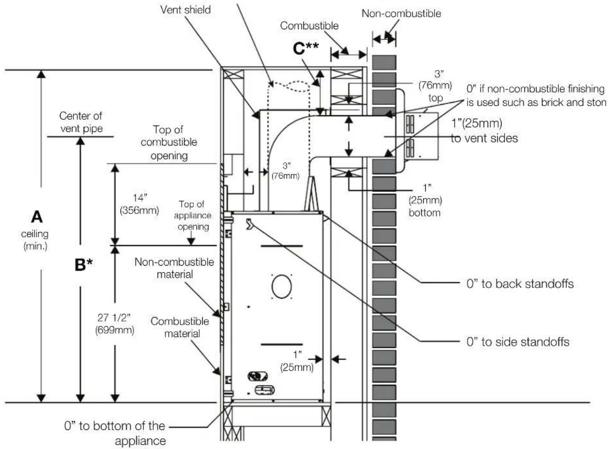
| BLX42 | BLX46 | BLX56 | |
| A | 56" 1422mm) | 60" (1524mm) | |
| B | 46" (1170mm) | 48" 1219mm) | |
| C | 6 1/2" (165mm) | 8" (203mm) | |
* See "venting requirements" and "venting installation" sections.
** Clearances within the enclosure may be higher, see "minimum framing dimensions" section.
note:
The vent shield is telescopic and must be adjusted to shield the full depth of the combustible wall penetration.
9.5 alcove enclosure
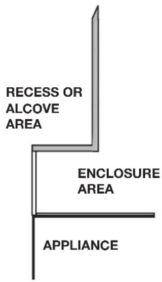
note:
Recesses or alcoves above the appliance must be made with non-combustible material and regular minimum clearances, as defined for combustible materials, must still be applied.
The recesses or alcoves can be made as deep as desired provided the minimum clearances to combustibles are maintained.
The minimum enclosure volume must be increased by no less than the volume of the recess. This adjustment can be made by increasing any or all of the height, width and depth of the enclosure.

WARNING
- Risk of fire!
- Never obstruct the front opening of the appliance.
- The front of the appliance must be finished with non-combustible materials such as brick, marble, granite, etc., provided that these materials do not go below the specified dimension, as illustrated.
- Do not strike, slam, or scratch. Do not operate appliance with glass removed, cracked, or scratched.
- Facing and/or finishing material must never overhang into the appliance opening.
- The glass door assembly is designed to pivot forward when relieving excess pressure that might occur. Finishing or other materials must not be located in the opening surrounding the door as this will interfere with the doors ability to relieve pressure.
10.1 log placement

WARNING
- Failure to position the logs in accordance with these diagrams or failure to use only logs specifically approved with this appliance may result in property damage or personal injury.
- Logs must be placed in their exact location in the appliance. Do not modify the proper log positions, since appliance may not function properly and delayed ignition may occur.
- The logs are fragile and should be handled with care.
PHAZER™ logs and glowing embers exclusive to Napoleon, provide a unique and realistic glowing effect that is different in every installation. Take the time to carefully position the glowing embers for a maximum glowing effect. Log colours may vary. During the initial use of the appliance, the colours will become more uniform as colour pigments burn in during the heat activated curing process. Blocked burner ports can cause an incorrect flame pattern.
Refer to the installation leaflet provided with the kit for log placement instructions.
10.1.1 BLX42 log placement
natural_image
Diagram of a reclining human figure inside a rectangular frame, no text or symbols present
natural_image
Diagram of a 3D object with two irregular shapes inside a rectangular frame (no text or labels)Driftwood log set (DLKBLP42)
natural_image
Illustration of a whale inside a transparent enclosure with measurement lines (no text or symbols)Oak log set (OLKBLP42) Birch log set (BL)
10.1.2 BLX46 log placement
natural_image
Simple line drawing of a reclining figure inside a rectangular frame (no text or symbols)Birch log set (BLKBLP46)

natural_image
Diagram of a mechanical or architectural component with layered structure and measurement indicators (no text or symbols)Driftwood log set (DLKBLP46)
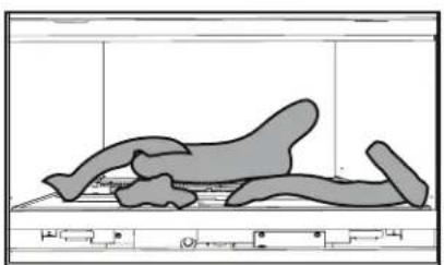
natural_image
Illustration of a reclining animal in a prone position within a rectangular frame (no text or symbols)Oak log set (OLKBLP46)
10.2.1 BLX56 log placement
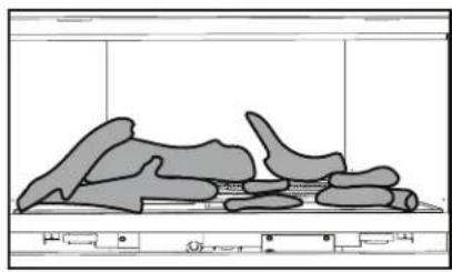
natural_image
Illustration of a fossilized dinosaur-like creature with segmented body and tail, enclosed in a rectangular frame (no text or symbols)Birch log set (BLKBLP46)
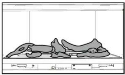
natural_image
Diagram of a biological specimen with irregularly shaped structures inside a transparent container (no text or labels)Driftwood log set (DLKBLP46)
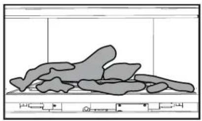
natural_image
Abstract diagram of irregular gray shapes on a rectangular base, no text or symbols presentOak log set (OLKBLP46)
10.2 door hanger trim installation
Slide the back edge of the door hanger trim down between the glass and the door frame. Insert downwards.
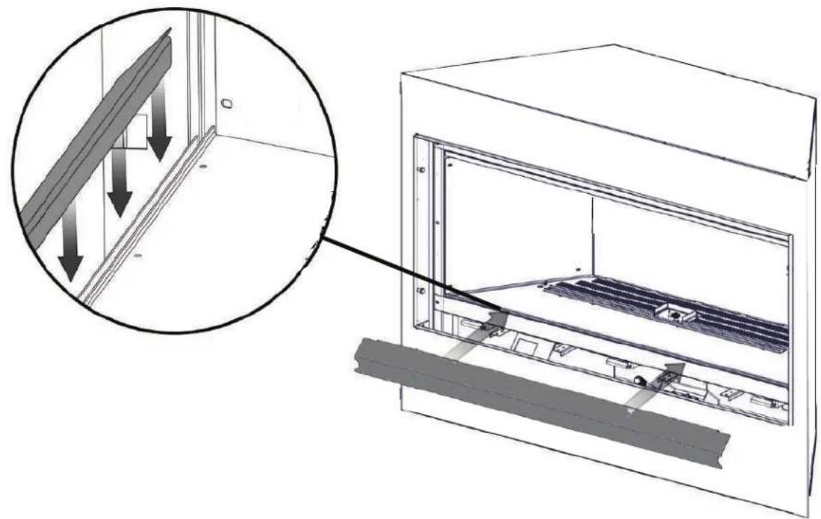
natural_image
Architectural diagram showing a window frame with insulation and ventilation system, plus an inset magnified view of the interior wall (no text or symbols)10.3 installing the finishing trim
- To install the finishing trim, remove the screws and shoulder bolts and set them aside.
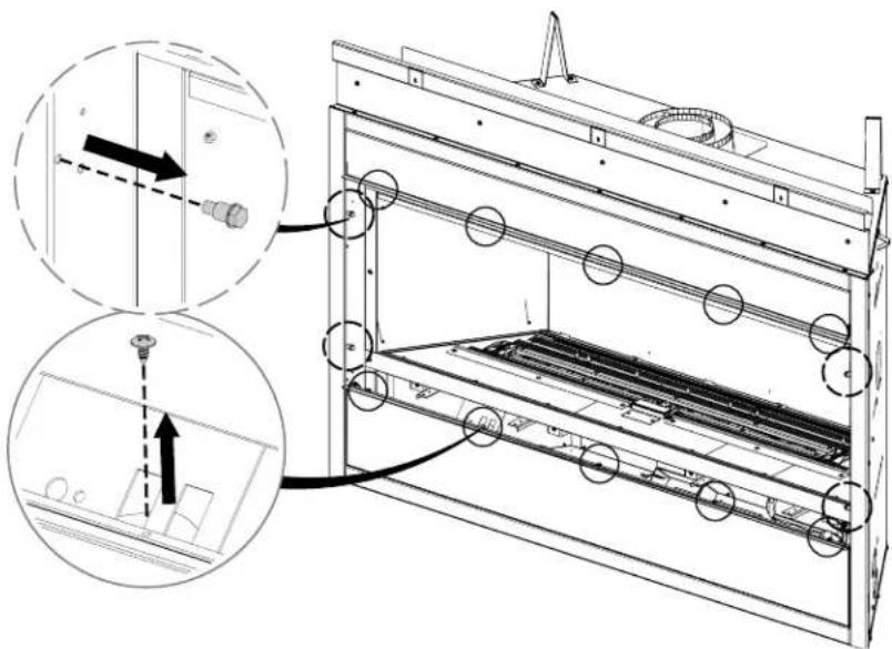
natural_image
Technical line drawing of a mechanical assembly with zoomed-in detail (no text or symbols)- Install the top 1" (25mm) trim and bottom 1 1/2" (38mm) trim with the flanges facing outward. Note the orientation of the trim. Adjust the trims to the desired depth.
important:
The top trim must go to the top of the fireplace opening or it will interfere with the function of the door.
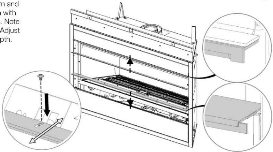
- Install the left (L) and right (R) trims with the flanges facing outward. Adjust the trims to the desired depth and tighten the screws and shoulder bolts.
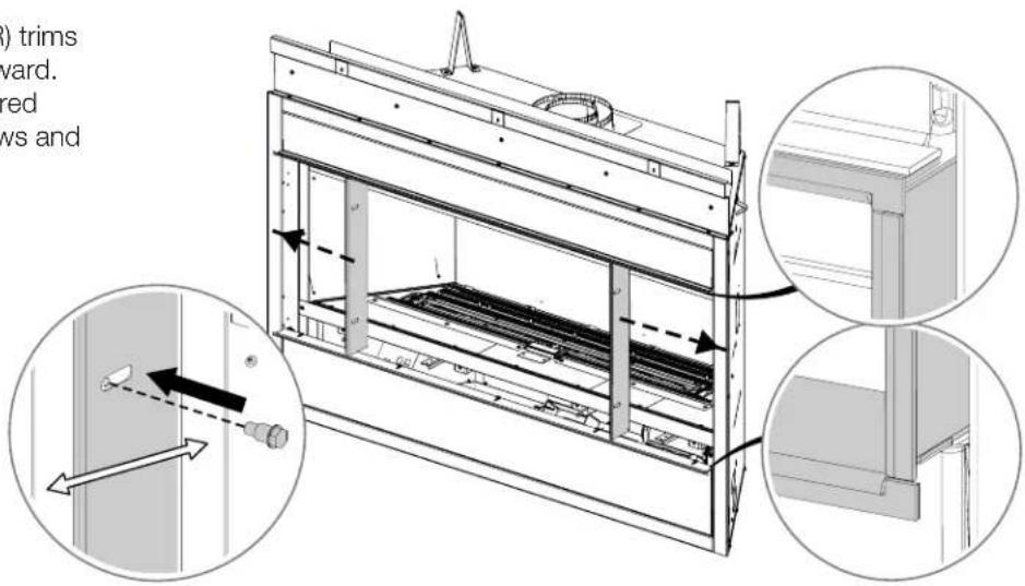
finishing
10.4 installing non-combustible board
! WARNING
- Non-combustible facing material must not project more than 4" (102mm) from the face of the door (all three sides). If greater projections are desired, increase the clearance to the sides and top by 2" (51mm) for every additional 1" (25mm) of projection. If using an optional surround, the same rule applies, starting from the top of the surround. Ensure clearances are maintained for surround removal, as it must lift off the appliance for maintenance.
| J | |
| BLX42 | 44" (1117mm) |
| BLX46 | 48" (1219mm) |
| BLX56 | 58" (1473mm) |
| K | |
| BLX42 | 38 1/2" (978mm) |
| BLX46 | 42 1/2" (1079mm) |
| BLX56 | 52 1/2" (1334mm) |
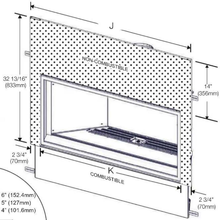
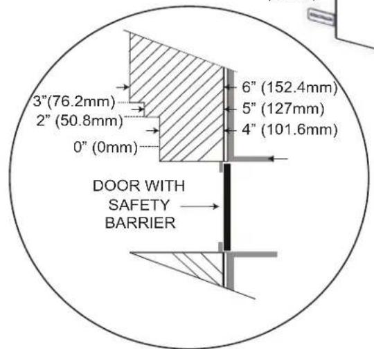
Joint Compound where required
Joint compounds such as Durabond 90 and tapes that are resilient to heat and cracking should be used when taping and mudding seams.
Setting tiles and grouting
We recommend you use tiles with a dry butt joint to be installed using a two-part mortar with an acrylic latex additive, such as Mapei Kerabond/Kerlastic, to allow for slight movement in the normal operation of the appliance. If grout is used between the tiles, a polymer-based grout, such as Mapei Ultracolour plus, is recommended.
Primer/Paint
For a painted surface, use a 100% acrylic latex primer and finish coat. Light coloured paints may discolour.
©
10.6 clearances around appliance (TV and valuable objects)
Flush installation without mantel
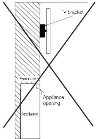
Flush installation with mantel
Recessed installation with protrusion
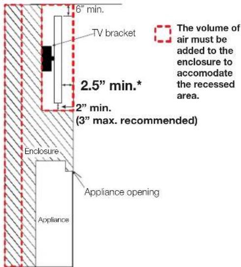
Flush installation with mantel
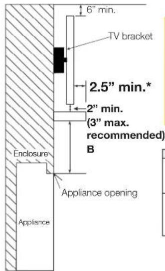
! WARNING
These applications are only acceptable when the Universal Heat Management kit is installed.
| A | See “minimum clearance to mantle” section (installation manual). |
| B | Mantle clearances reduced from opening with the use of the universal heat management system. |
Partially recessed installation with mantel

* TV applications were tested with the minimum enclosure dimensions and the maximum recess permissible. This data is provided in good faith and is not a guarantee for every application and television. Care and consideration should be taken when planning these installations to ensure the temperatures around the TV meet all manufacturer's recommended operating temperatures. Increasing the height of the mantel and/or TV above the fireplace opening, the protrusion of mantel and the volume of the enclosure all have the effect of reducing the temperature above the fireplace. It is always recommended to use the optional heat management kit when considering mounting a television above the fireplace.
10.7 safety barrier & glass door installation / removal

WARNING
• Glass may be hot. Do not touch glass until cooled.
- If equipped with door latches that are part of a safety system, they must be properly engaged. Do not operate the appliance with latches disengaged.
- Facing and/or fi nishing materials must not interfere with air flow through air openings, louvre openings, operation of louvres, or doors/access for service. Observe all clearances when applying combustible materials.
- Before door is removed, turn the appliance off and wait until appliance is cool to the touch. Doors are heavy and fragile so handle with care.
A barrier designed to reduce the risk of burns from the hot viewing glass is provided with the appliance and must be installed.
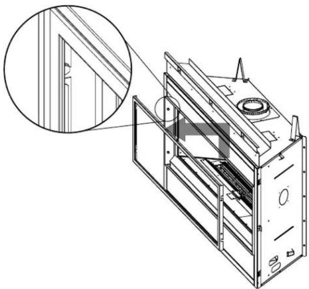
natural_image
Technical line drawing of a mechanical device with an inset close-up showing a window detail (no text or symbols)Before the glass door can be removed, the safety barrier must be removed. Lift the safety barrier off the four shoulder screws and remove from the appliance.
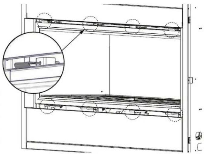
natural_image
Technical line drawing of a multi-level storage or rack system with an inset magnified detail (no text or symbols)Leave a hand on the glass door during entire door removal. The glass door is secured to the firebox with four (BLX42), six (BLX46), or eight (BLX56) spring latches. Pull the handles of the latches forward, then lift/lower the latches out from the door frame to release the door. Next, lift the door up until the bottom edge clears the bottom shoulder screws of the appliance. Carefully grip the top and bottom of the door lifting it off the appliance.
Reverse these steps to re-install the door and safety barrier. The position of the safety barrier can be adjusted according to the depth of the adjustable finishing trim. See “adjusting the finishing trim” section.
Ensure safety barrier is installed correctly.
note:
These spring latches make up the spring relief system for the appliance. Ensure the door opens freely and closes sealed.
note:
When mounting the door, ensure there is equal space on both the left and the right side. This allows for easy installation of the front.
10.8 optional glass media installation

WARNING
- Clean the glass media prior to installation. Before applying the cleaned glass, ensure that it is dry.
- Do not change or substitute the glass media material provided with this appliance. If replacing, use only the replacement glass media available from your local authorized dealer / distributor.
- Glass media over the burner must not be more than one layer high. More than one layer over the burner will cause flame lifting and sooting problems.
- Do not place any media (glass or vermiculite) in or around the pilot opening and/or on the burner ports. This will interfere with the pilot operation.
Evenly spread the glass media onto the media tray, covering the burner tube and tray. Ensure no glass media falls into the pilot opening. If this happens, insert a clean bag into your vacuum cleaner and vacuum out the glass media. Replacement glass can be purchased from your local dealer / distributor.
note:
Do not use more media than what was certified with the appliance.
Cleaning Glass Media
Glass media may have a fi ne oil residue that needs to be cleaned prior to installation. Clean the glass with mild dish soap, drain, rinse thoroughly and dry before placing over the burner.
note:
Care must be taken to ensure glass media are kept clear of the pilot area on the media tray and are not interfering with the pilot operation.
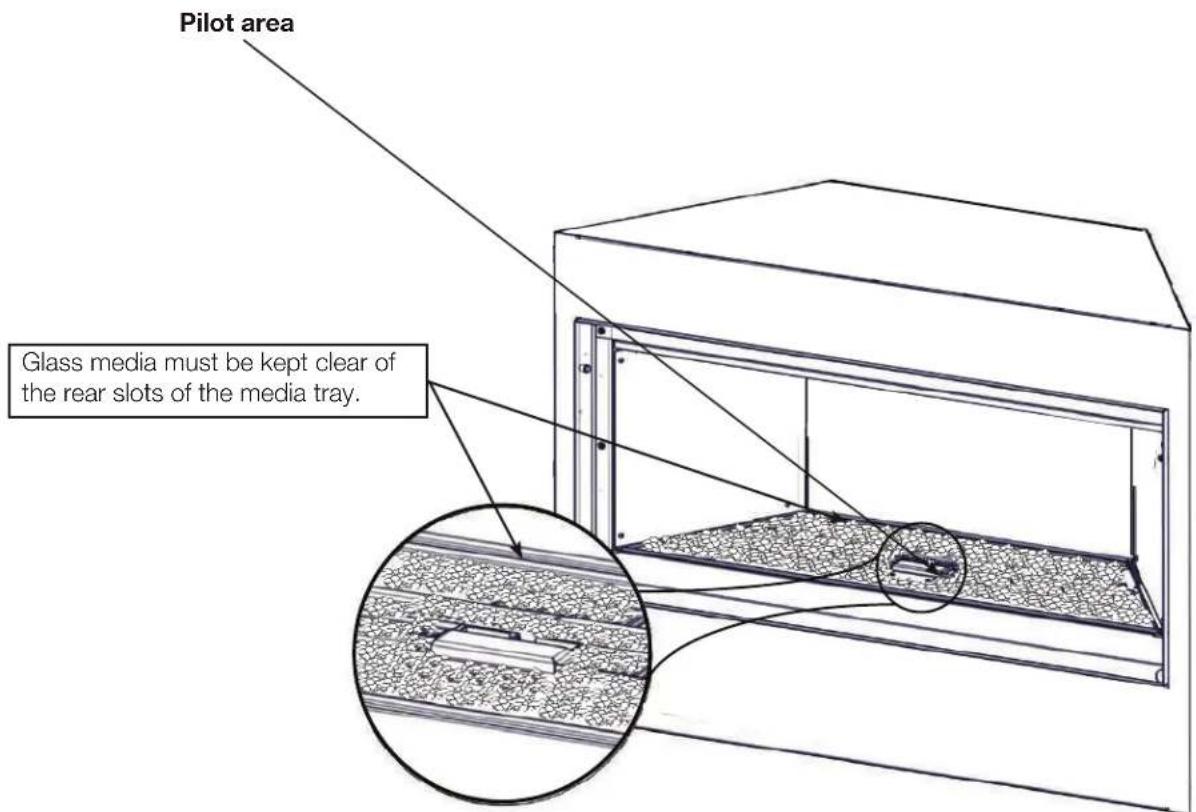
10.9 night light replacement
Your appliance comes equipped with our Night Light ^™ . The light has been pre-wired and can be controlled from the remote control. It is recommended that the Night Light ^™ be in the "OFF" position when the appliance is on. In the event the lamp or lens needs to be replaced:
- Unplug the appliance from power.
- Remove the 4 screws that secure the lens frame. This frame retains the glass lens.
- The lamp can now be accessed. It will pull straight out of the socket.
note:
Do not handle the lamp (bulb) with bare fingers as it may be hot. Use a clean, dry cloth for protection.
- Replace the lamp with Wolf Steel parts only, as lamp and lens are special "high temperature" products.
- When re-installing, ensure integrity of gasket seal.
note:
Do not over-tighten the screws, as this could break the lens.
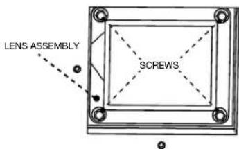
FIREBOX TOP
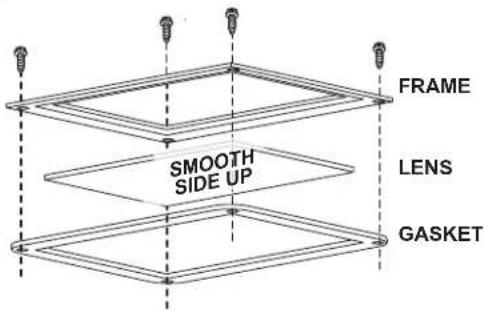
- Ensure the appliance is completely cool before starting installation.
- To avoid danger of suffocation, keep the packaging bag away from babies and children. Do not use in cribs, beds, carriages or play pens. This bag is not a toy. Knot before throwing away.
A. Remove the safety barrier by lifting it up and off of the appliance.
B. Remove the door from the appliance by releasing the door latches.
C. Remove door hanger trim.
D. Remove cover plates (Fig. 1).
E. Remove burner assembly (Fig. 2).
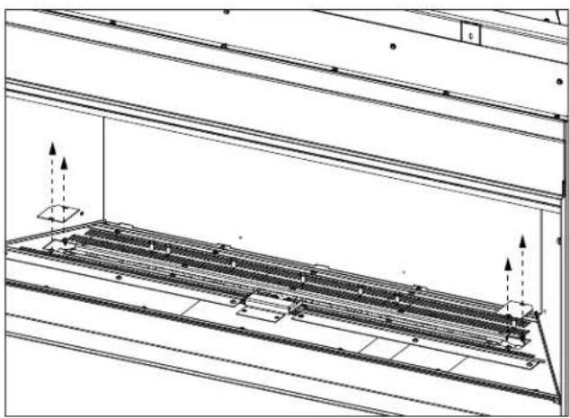
natural_image
Technical line drawing of a structural frame with support columns and directional arrows indicating movement (no text or symbols)(Fig. 1)
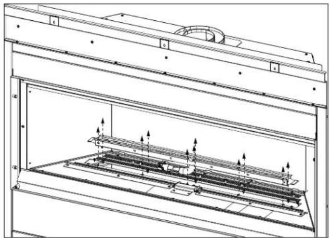
natural_image
Technical line drawing of a mechanical assembly with internal components and directional arrows (no text or symbols)(Fig. 2)
F. Remove media tray (Fig. 3).
G. Remove access plate and gasket (Fig. 4).
H. Disconnect the wire harness connectors.
I. Remove screw securing blower bracket then slide blower assembly to the left and remove (Fig. 5).
J. Replace with new blower.
K. Reverse the process to reassemble the interior of the firebox.
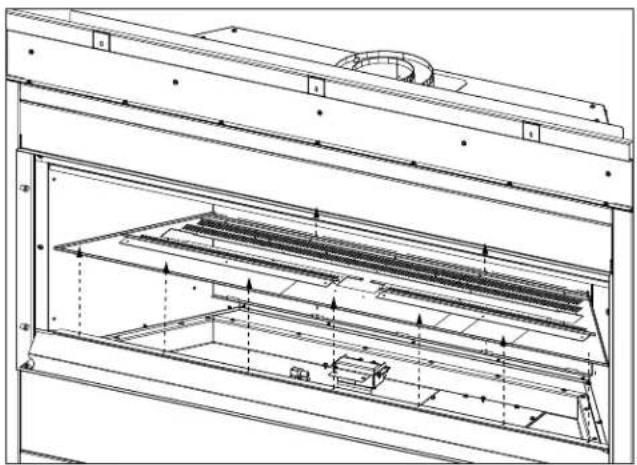
natural_image
Technical line drawing of a multi-level industrial or mechanical assembly with internal channels and mounting brackets (no text or symbols)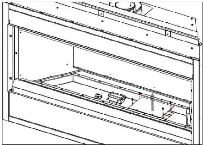
natural_image
Technical line drawing of a mechanical assembly with internal components and mounting brackets (no text or symbols)(Fig. 3) (Fig. 4)
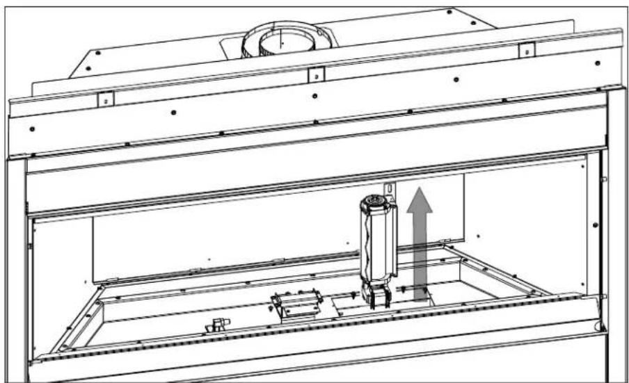
natural_image
Technical line drawing of a mechanical assembly with internal components and an upward arrow indicating motion (no text or symbols present)(Fig. 5)
11.1 restricting vertical vents
Vertical installations may display a very active flame. If this appearance is not desirable, the vent exit must be restricted using a restrictor vent kit. Refer to the "replacement parts" section of the owner's manual for the appropriate kit. This will reduce the velocity of the exhaust gases, slowing down the flame pattern and creating a more traditional gentle flame appearance. Specific instructions are included with the kit.
11.2 venturi adjustment
note:
An air shutter access plate has been provided for initial flame appearance setup. It becomes more difficult to adjust once the appliance has been finished.
This appliance has an air shutter that has been factory set open according to the chart below:
Regardless of venturi orientation, closing the air shutter will cause a more yellow flame, but can lead to carbonization. Opening the air shutter will cause a more blue flame, but can cause flame lifting from the burner ports. The flame may not appear yellow immediately; allow 15 to 30 minutes for the final flame colour to be established.
AIR SHUTTER ADJUSTMENT MUST ONLY BE DONE BY A QUALIFIED INSTALLER!
Venturi Burner
Orifice
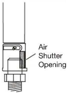
note:
It is important that the orifice is securely inserted into the venturi.
| VENTURI ADJUSTMENT CHART | |
| NG 1/16" (1.6mm) | |
| LP 1/4" (6.4mm) |
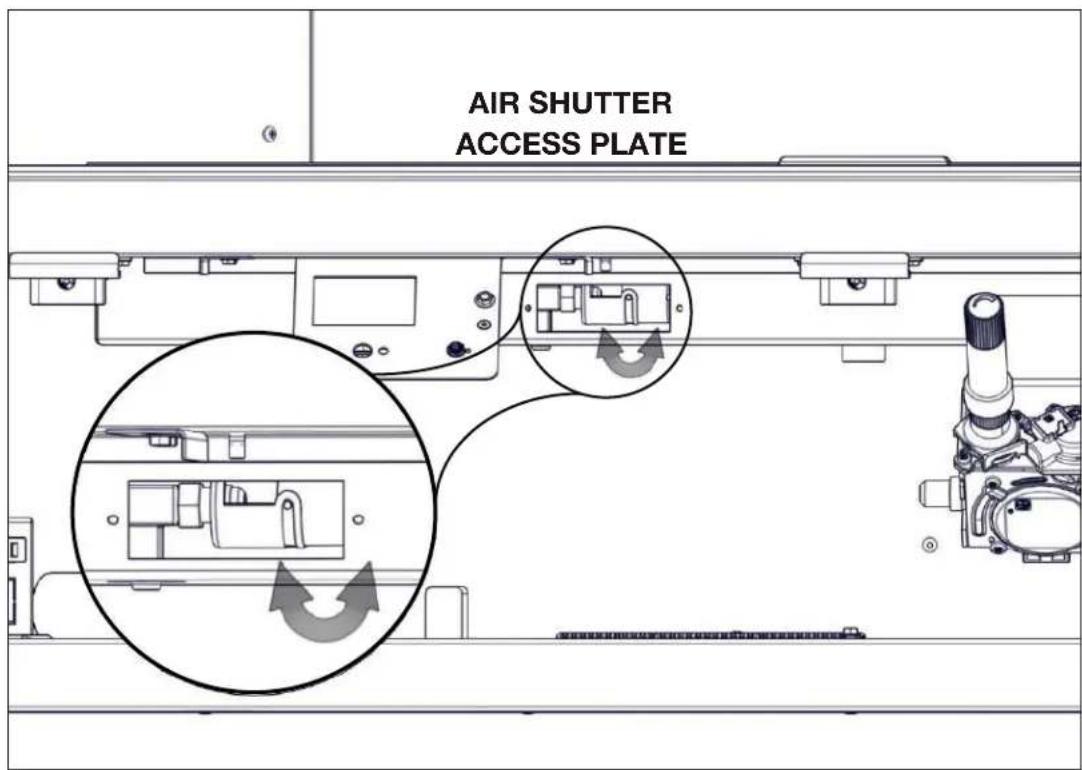
11.3 pilot burner adjustment
Adjust the pilot screw to provide properly sized flame. Turn in a clockwise direction to reduce the gas flow.
Check Pressure Readings:
Inlet pressure can be checked by turning screw (A) counterclockwise 2 or 3 turns and then placing pressure gauge tubing over the test point. Gauge should read as described on the chart below. Check pressure with main burner operating on "HI".
Outlet pressure can be checked the same as above using screw (B). Gauge should read as described on the chart below. Check pressure with main burner operating on "HI".
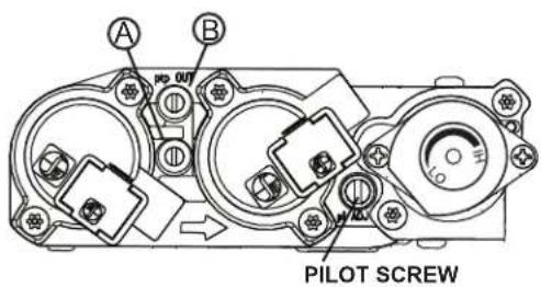
After taking pressure readings, be sure to turn screws clockwise firmly to reseal. Do not overtorque.
Leak test with a soap and water solution.
Prior to pilot adjustment, ensure that the pilot assembly has not been painted. If overspray or painting of the pilot assembly has occurred remove the paint from the pilot assembly, or replace. Fine emery cloth or a synthetic scrub pad (such as Scotch-Brite™) can be used to remove the paint from the pilot hood, electrode and flame sensor.
| Pressure | Natural Gas (inches) | Natural Gas (millibars) | Propane (inches) | Propane (millibars) |
| Inlet | *7" (minimum 4.5") | 17.4mb (minimum 11.2mb) | 13" (minimum 11") | 32.4mb (minimum 27.4mb) |
| Outlet | 3.5" 8.7mb | 10" 24.9mb |
\*Maximum inlet pressure not to exceed 13"
11.4 flame characteristics
It's important to periodically perform a visual check of the pilot and burner flames. Compare them to the illustration provided. If any flames appear abnormal, call a service person.
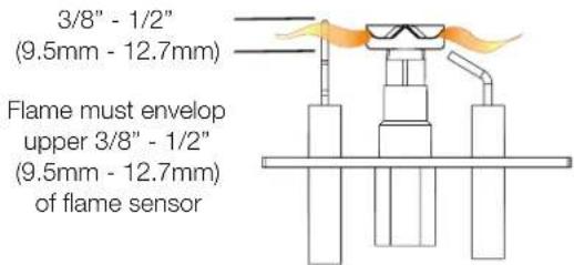
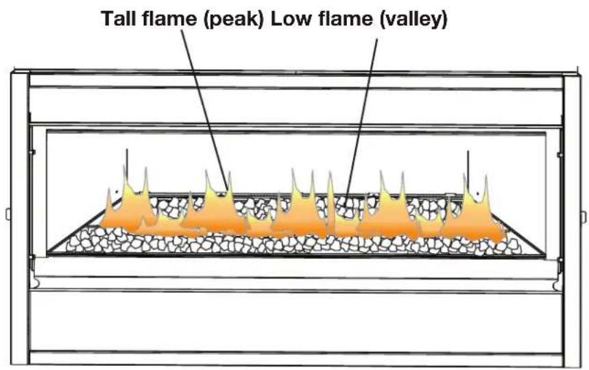

WARNING
- Turn off the gas and electrical power before servicing the appliance.
- Appliance may be hot. Do not service until appliance has cooled.
- Do not use abrasive cleaners on glass.
- Do not paint the pilot assembly.
This appliance and its venting system (if equipped) should be inspected before use and at least annually by a qualified service person. The following suggested checks should be performed by a qualified technician. The appliance area must be kept clear and free of combustible materials, gasoline, or other flammable vapors and liquids. The flow of combustion and ventilation air must not be obstructed.
note:
Caution: Label all wires prior to disconnection when servicing controls. Wiring errors can cause improper and dangerous operation. Verify proper operation after servicing.
- In order to properly clean the burner and pilot assembly, remove the logs, rocks and/or glass to expose both assemblies.
- Keep the control compartment, media, burner, air shutter opening and the area surrounding the appliance clean by vacuuming or brushing, at least once a year.
- Check to see that all burner ports are burning. Clean out any of the ports which may not be burning or are not burning properly.
- Check to see that the pilot flame is large enough to engulf the flame sensor and/or thermocouple / thermopile as well as it reaches the burner.
- If your appliance is equipped with a safety barrier, cleaning may be necessary due to excessive lint / dust from carpeting, pets, etc. simply vacuum using the brush attachment.
- If your appliance is equipped with relief doors, ensure the system performs effectively. Check that the gasket is not worn or damaged. Replace if necessary.
- Reinstall the cleaned logs, rocks or glass. Failure to properly position the media may cause carboning which can be distributed in the surrounding living area, inside the fi rebox and on exterior surfaces surrounding vent termination.
- Check to see that the main burner ignites completely on all ports when turned on. A 5 to 10 second total light-up period is satisfactory. If ignition takes longer, consult your local authorized dealer / distributor.
- Visually inspect the appliance for carbon build up. Using a small whisk or brush, brush off the carbon and vacuum up or sweep into garbage.
- This step is not applicable for Vent Free appliances: Check to see that the appliance is venting correctly. Ensure chimney system is safe and unobstructed. (If for any reason the vent air intake system is disassembled, re-install and re-seal per the instructions provided for the initial installation).
12.1 care of glass

WARNING
- Do not clean glass when hot! Do not use abrasive cleaners to clean glass.
Buff lightly with a clean dry soft cloth to remove accumulated dust or fingerprints. Clean both sides of the glass after the first 4 hours of operation with an ammonia-free glass cleaner.
note:
Vinegar-based glass cleaners have demonstrated an ability to provide a clean, streak free glass surface.
Thereafter, clean as required. If the glass is not kept clean permanent discoloration and / or blemishes may result. Contact your local authorized dealer / distributor for complete cleaning instructions.
Razor blades, steel wool, or other metallic objects must not be used on both surfaces of the glass. Doing so can remove a thin layer of metal from the razor blades, steel wool, or other metallic objects that may then be deposited onto the coating. This can result in a discoloured stain or scratch-like mark. More importantly, this can scratch the glass surface, thereby reducing its strength.
Do not operate the appliance with broken glass, as leakage of flue gases may result.
Contact your local authorized dealer / distributor for complete cleaning instructions.
If the glass should ever crack or break while the fire is burning, do not open the door until the fire is out. Do not operate the appliance until the glass has been replaced. Contact you local authorized dealer / distributor for replacement parts. DO NOT SUBSTITUTE MATERIALS.
This appliance is factory equipped with 4mm tempered glass. Use only replacement parts as supplied by the appliance manufacturer. DO NOT SUBSTITUTE MATERIALS.
12.2 annual maintenance

WARNING
• Annual maintenance should be performed by a qualified service technician
- The fi rebox becomes very hot during operation. Let the appliance cool completely or wear heat resistant gloves before conducting service.
- Never vacuum hot embers.
- Do not paint the pilot assembly
- This appliance will require maintenance which should be planned on an annual basis.
- Service should include cleaning, battery replacement, venting inspection and inspection of the burner, media, and fi rebox. Refer to the door removal section and remove the door as instructed.
- Carefully remove media if necessary (logs, glass, brick panels, etc.).
- Using a vacuum with soft brush attachment, gently remove any dirt, debris, or carbon build up from the logs, fi rebox, and burner. For glass media, follow the installation instructions for pre-cleaning.
- Gently remove any build-up on the pilot assembly including thermopile, thermocouple, flame sensor, and igniter (if equipped).
note:
Clean flame sensor using a fi ne emery cloth or a synthetic scrub pad (such as Scotch-Brite™) to remove any oxides. Clean the pilot assembly using a vacuum with a soft brush attachment. It is important that the pilot assembly is not painted.
- Inspect all accessible gaskets and replace as required.
- If equipped with a blower, access the blower and clean using a soft brush and vacuum.
- Re-assemble the various components in reverse order.
- Inspect the relief system. The appliance relieves through the main glass door or through the flaps on the fi rebox top. Ensure they open freely, and close sealed.
- Check the gas control valve pilot and Hi / Lo knobs move freely, if equipped. Replace if any stiffness in movement is experienced.
- Check for gas leaks on all gas connections up and downstream from the gas valve including pilot tube connections.
12.3 glass / door replacement

WARNING
- Do not use substitute materials.
• Glass may be hot. Do not touch glass until cooled. - Care must be taken when removing and disposing of any broken door glass or damaged components. Be sure to vacuum up any broken glass from inside appliance before operation.
- Do not strike, slam, or scratch. Do not operate appliance with glass removed, cracked, broken, or scratched.
Replacement glass/frame assembly shall be replaced as a complete unit as supplied by the appliance manufacturer.

WARNING
- Failure to position the parts in accordance with this manual or failure to use only parts specifically approved with this appliance may result in property damage or personal injury.
Contact your dealer for questions concerning prices and policies on replacement parts. Normally, all parts can be ordered through your Authorized dealer / distributor.
For warranty replacement parts, a photocopy of the original invoice will be required to honour the claim.
When ordering replacement parts always give the following information:
- Model & Serial Number of appliance
• Installation date of appliance - Part number
• Description of part - Finish
Parts, part numbers, and availability are subject to change without notice.
Parts identified as stocked will be delivered within 2 to 5 business days for most delivery destinations.
Parts not identified as stocked will be delivered within a 2 to 4 week period, for most cases.
Parts identified as 'SO' are special order and can take up to 90 days for delivery.
13.1 overview
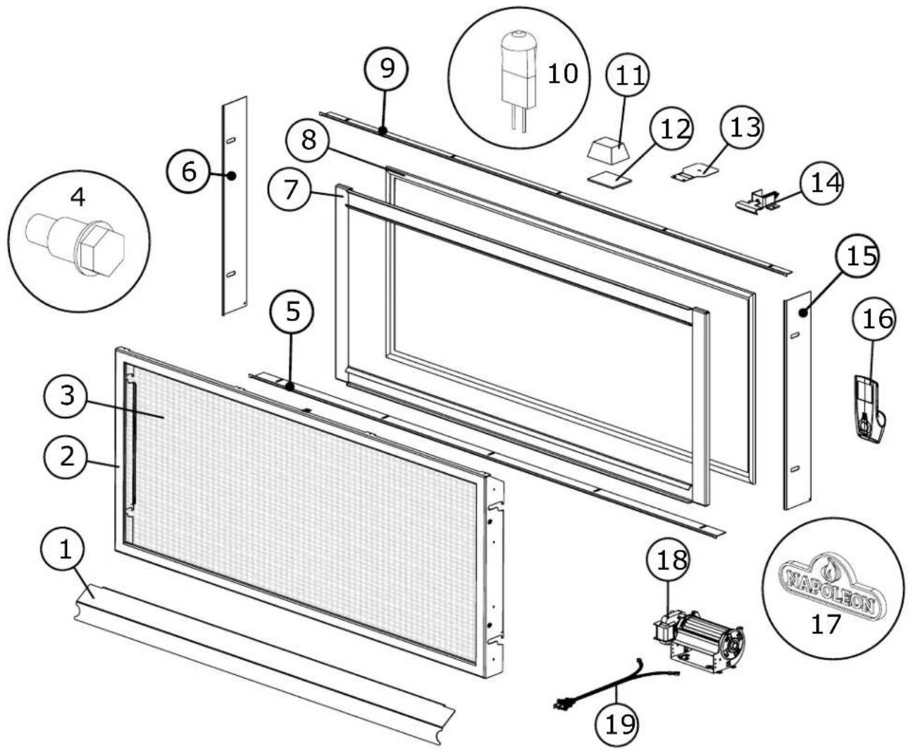
| Ref. | Part # Description Stocked | ||
| 1 W7 | 15-10006524-SER Door hanger trim (BLX42) | ||
| W715-10005597-SER Door hanger trim (BLX46) | |||
| W715-10006095-SER Door hanger trim (BLX56) | |||
| 2 W0 | 10-10006547-SER Safety barrier assembly (BLX42) Yes | ||
| W010-10005947-SER Safety barrier assembly (BLX46) | |||
| W010-10006300-SER Safety barrier assembly (BLX56) Yes | |||
| 3 W5 | 65-0343-SER Premium safety screen (BLX42) Yes | ||
| W565-0350-SER Premium safety screen (BLX46) Yes | |||
| W565-0344-SER Premium safety screen (BLX56) Yes | |||
| 4 W5 | 70-0192 Shoulder screw | ||
| 5 W7 | 15-10006527-SER Finishing bottom trim (BLX42) | ||
| W715-10005475-SER Finishing bottom trim (BLX46) | |||
| W715-10005937-SER Finishing bottom trim (BLX56) | |||
| 6 W7 | 15-10005474-SER Finishing left side trim | ||
| 7 W0 | 10-10006566-SER Door assembly (BLX42) | ||
| W010-10006519-SER Door assembly (BLX46) | |||
| W010-10006468-SER Door assembly (BLX56) | |||
| 8 W5 | 62-0060 Door gasket kit (BLX42/46) Yes | ||
| W562-0009 Door gasket kit (BLX56) Yes | |||
| 9 W7 | 15-10006525-SER Finishing top trim (BLX42) | ||
| W715-10006499-SER Finishing top trim (BLX46) | |||
| W715-10006094-SER Finishing top trim (BLX56) | |||
| 10 W | 387-0006 Halogen bulb | ||
| 11 W | 405-0087 Light assembly | ||
| 12 W | 300-0067 Ceramic glass lens | ||
| 13 RP | 4 4" Restrictor plate | Yes | |
| RP5 5" Restrictor plate | Yes | ||
| 14 W | 010-3554 Door latch | ||
| 15 W | 715-10005506-SER Finishing right side trim | ||
| 16 W | 660-0126-SER PF2 Remote | ||
| 17 W | 385-2010 Napoleon logo | Yes | |
| 18 W | 062-0087 Blower | ||
| 19 W | 750-0159 Blower wire harness |
13.2 valve train assembly
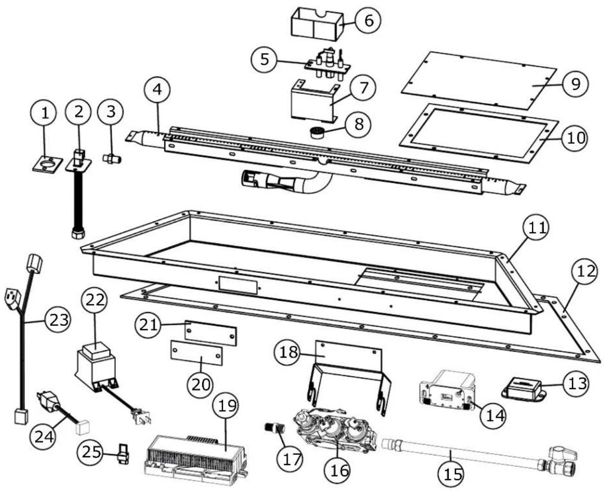
*Part not illustrated.
| Ref. | Part # Description Stocked | ||
| 1 W290-0157 Manifold gasket | |||
| 2 W432-0103 Manifold flex pipe | |||
| 3 W456-0045 Burner orifice #45 NG (BLX42) Yes | |||
| W456-0043 Burner orifice #43 NG (BLX46) Yes | |||
| W456-0041 Burner orifice #41 NG (BLX56) Yes | |||
| 4 W100-0299-SER Burner assembly (BLX42) | |||
| W100-0223-SER Burner assembly (BLX46) | |||
| W100-0310-SER Burner assembly (BLX56) | |||
| 5 W010-10006190 Pilot assembly NG | |||
| 6 W585-10006097 Pilot Shield Yes | |||
| 7 W080-10006098 Pilot Bracket | |||
| 8 W105-0001 Bushing | |||
| 9 W200-0841 Base valve train cover (BLX42) | |||
| 10 W290-0926 Blower access door gasket (BLX42) | |||
| 11 W035-0529 Valve train base (BLX42) | |||
| 12 W290-0927 Valve train gasket (BLX42) | |||
| 13 W190-0090 Bluetooth control module | |||
| 14 W350-0655 Battery housing | |||
| 15 W175-0217 Flex connector w/ valve Yes | |||
| 16 W725-0056 Valve NG Yes | |||
| 17 W445-0038 Connector | |||
| 18 W080-1762 Valve bracket | |||
| 19 W190-0177-SER Control board Yes | |||
| 20 W200-0629 Access cover | |||
| 21 W290-0335 Venturi door gasket | |||
| 22 W707-0019 Transformer | |||
| 23 W750-0358 Light / fan pigtail | |||
| 24 W750-0294 Power cord wire (18") | |||
| 25 W175-0355 Female X4 ON/OFF jumper | |||
| 26* W750-0268 Battery housing wire harness | |||
| 27* W750-0276 Proflame 2 wire harness | |||
| 28* W750-0317 Extension wire harness | |||
13.2.1 conversion kits
| Ref. | Part # Description Stocked | ||
| 1 W1 | 75-10006809 Conversion kit NG - LP (BLX42) | ||
| W175-10006810 Conversion Kit LP - NG (BLX42) | |||
| 2 W1 | 75-10006811 Conversion kit NG - LP (BLX46) | ||
| W175-10006812 Conversion Kit LP - NG (BLX46) | |||
| 3 W1 | 75-10006813 Conversion kit NG - LP (BLX56) | ||
| W175-10006814 Conversion Kit LP - NG (BLX56) |
replacement parts
13.3 logs
13.3.1 birch log set
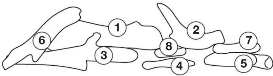
BLKBLP56 illustrated
| Ref. Part # Description Stocked | |||
| 1 W135-1046 Left rear log (Log #1) | |||
| 2 W135-1047 Right rear log (Log #2) | |||
| 3 W135-1048 Left front log (Log #3) | |||
| 4 W135-1049 Middle front log (Log #4) | |||
| 5 W135-1050 Right front log (Log #5) | |||
| 6 W135-1051 Left crossover log (Log #6) | |||
| 7 W135-1052 Middle crossover log (Log #7) | |||
| 8 W135-1053 Middle front crossover log (Log #8) | |||
13.3.2 driftwood log set
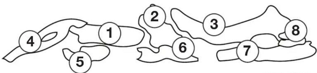
DLKBLP56 illustrated
| Ref. Part # Description Stocked | |||
| 1 W135-1028 Rear left log (Log #1) | |||
| 2 W135-1029 Rear center log (Log #2) | |||
| 3 W135-1030 Rear right log (Log #3) | |||
| 4 W135-1031 Crossover left log (Log #4) | |||
| 5 W135-1032 Front bottom left log (Log #5) | |||
| 6 W135-1033 Front top left log (Log #6) | |||
| 7 W135-1034 Front center log (Log #7) | |||
| 8 W135-1035 Front right log (Log #8) | |||
13.3.3 oak log set
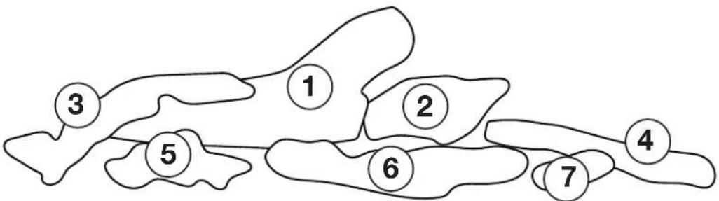
OLKBLP56 illustrated
| Ref. | Part # Description Stocked | ||
| 1 W1 | 35-1037 Rear log (Log #1) | ||
| 2 W1 | 35-1038 Right rear log (Log #2) | ||
| 3 W1 | 35-1039 Left crossover log (Log #3) | ||
| 4 W1 | 35-1040 Right crossover log (Log #4) | ||
| 5 W1 | 35-1041 Left front log (Log #5) | ||
| 6 W1 | 35-1042 Middle front log (Log #6) | ||
| 7 W1 | 35-1043 Right front log (Log #7) |

WARNING
- Always light the pilot whether for the first time or if the gas supply has run out, with the glass door open or removed.
- Turn off gas and electrical power before servicing the appliance.
- Appliance may be hot. Do not service until appliance has cooled.
- Do not use abrasive cleaners
symptom problem test solution
| Main burner flame is a blue, lazy, transparent flame.(This is not applicable in outdoor appliances) | Blockage in vent. - Remove blockage. In really cold conditions, ice buildup may occur on the terminal and should be removed as required. (To minimize this from reoccurring, the vent lengths that pass through unheated spaces (attics, garages, crawl spaces) should be wrapped with an insulated mylar sleeve). | |||
| Incorrect installation. - Refer to “venting” section to ensure correct installation. | ||||
| Flames are consistently too large or too small. Carboning occurs. | Appliance is over-fi red or under-fi red. | - Check pressure readings:Inlet pressure can be checked by turning screw (A) counter-clock-wise 2 or 3 turns and then placing pressure gauge tubing over the test point. Gauge should read as described on the chart below.Check that main burner is operating on ‘HI’. Outlet pressure can be checked the same as above using screw (B). Gauge should read as described on the chart below. Check that main burner is operating on ‘HI’. After taking pressure readings, be sure to turn screws clockwise firmly to reseal. DO NOT OVER TORQUE.Leak test with a soap and water solution. | ||
| IGNITOR(SPARK) | ||||
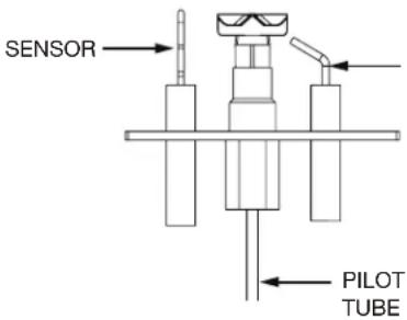 | Pressure | Natural Gas(inches) | Natural Gas(millibars) | Propane(inches) |
| Inlet | *7"(minimum 4.5") | 17.4mb(minimum 11.2mb) | 13"(minimum 11") | |
| Outlet | 3.5" | 8.7mb | 10" | |
*Maximum inlet pressure not to exceed 13" w.c.
| Air shutter improperly adjusted. | - Return air shutter to specified opening, see "venturi adjustments" section in the installation manual. | |
| Carbon is being deposited on glass, logs, rocks, media, or combustion chamber surfaces. | Air shutter is blocked. - Ensure air shutter opening is free of lint or other obstructions. | |
| Flame is impinging on the glass, logs, rocks, media or combustion chamber. | - Ensure the media is positioned correctly in the appliance.- Open air shutter to increase the primary air.- Check the input rate: check the manifold pressure and orifice size as specified by the rating plate.- Ensure door gaskets are not broken or missing and the seal is tight.- Ensure vent liners are free of holes and well sealed at all joints.- Check that minimum rise per foot (meters) has been adhered to for any horizontal venting. | |
| White / grey film forms. | Sulphur from fuel is being deposited on glass, logs, or combustion chamber surfaces. | - Clean the glass with a recommended gas fi replace glass cleaner. DO NOT CLEAN GLASS WHEN HOT.- If deposits are not cleaned off regularly, the glass may become permanently marked. |
| Exhaust fumes smelled in room, headaches. | Appliance is spilling.(This is not applicable in outdoor appliances). | - Check door seal.- Check for exhaust damage.- Check that venting is installed correctly.- Room is in negative pressure; increase fresh air supply. |
symptom problem test solution
| Pilot will not light. Makes noise with no spark at pilot burner. | Wiring: short, loose, or damaged connections (poor flame rectification). | - Verify the thermocouple/sensor is clean and the wiring is undamaged.- Verify the interrupter block is not damaged or too tight. Verify connections from pilot assembly are tight; also verify the connections are not grounding out to any metal. (Remember, the flame carries the rectification current, not the gas. If flame lifts from pilot hood, the circuit is broken. A wrong orifice or too high of an inlet pressure can cause the pilot flame to lift). The sensor rod may need cleaning. |
| No signal from remote with no pilot ignition. | - Reprogram receiver code.- Replace receiver. | |
| Poor grounding. | - Verify the valve / pilot assembly are properly grounded | |
| Improper switch wiring. | - Troubleshoot the system with the simplest on/off switch. | |
| Dirty, painted, or damaged pilot and/or dirty sensor rod. | - Clean sensor rod with a green Scotch-BriteTM pad to remove any contamination that may have accumulated. Verify continuity with multimeter with ohms set at the lowest range. | |
| Pilot sparks but will not light. | Gas supply. | - Verify that the incoming gas line ball valve is "open".- Verify that the inlet pressure reading is within acceptable limits, inlet pressures must not exceed 13" W.C. (32.4mb). |
| Out of propane gas. | - Fill the tank. | |
| Pilot supply line may contain air. | - Repeat ignition process several times or purge the pilot supply line. | |
| Incorrect wiring / grounding. | - Ensure correct polarity of wiring of thermocouple (if equipped).- Verify pilot assembly / valve are properly grounded. | |
| Receiver (if equipped). | - Reset program: hold reset button on receiver and wait for 2 beeps. Release after second beep. Press small flame button on remote within 20 seconds, you will hear an additional beep (this signals a successful reset).- Replace receiver. | |
| Valve. | - Check valve and replace if necessary (Do not to overtighten thermocouple). | |
| Burner continues to spark and pilot lights but main burner does not light. | Short or loose connection in sensor rod. | - Verify all connections. Verify the connections from the pilot assembly are tight. Also, verify these connections are not grounding out to any metal. |
| Dirty, painted, or damaged pilot assembly components. | - Clean using a green Scotch-BriteTM pad to remove any contamination that may have accumulated on the sensor rod, pilot hood, ignitor, or flame sensor. Verify continuity with multimeter with ohms set at the lowest range. | |
| Remote wall switch is in "off" position; burner comes on. | Wall switch mounted upside down. | - Reverse. |
| Remote wall switch and/or wire is grounding. | - Replace.- Check for ground (short); repair ground or replace wire. | |
| Faulty wire | - Replace. | |
| Remote and / or receiver is not functioning properly. | Remote controls lights but no spark or flame. (Remote is locked out). | - Reset by turning power source off then on. |
| note:If back up batteries are installed, they must also be removed to re-program | ||
| Receiver or remote has low battery. | - Replace batteries. | |
| Appliance functions but does not respond to receiver / remote | - Ensure appliance is being operated by the same device that turned it on. Remote controls function if appliance was turned on by remote. Receiver controls function if appliance was turned on by receiver. | |
| Error with synchronizing. | - Reset receiver and remote. | |
| Remote too far away from receiver. | - Refer to "wiring diagram" section. | |
| Wire connector pins are bent. | - Straighten pins. | |
| Valve wiring is damaged. | - Replace valve. |
symptom problem test solution
| Lights or blower won't function (if equipped). | Control module switch in wrong position. | - | Verify ON/OFF switch is in the “I” position which denotes on. |
| COM switch is unplugged. | - | Verify “COM” switch is plugged into the front of the control module. | |
| Flames are very aggressive. | Door is ajar. | - | Ensure door is secured properly. |
| Venting action is too great. | - | Check to ensure venting is properly sealed or restrict vent exit with restrictor plate. (Not available in all appliances). | |
| Appliance won't perform any functions. | No power to the system. | - | Check breaker to verify it's in the “on” position. |
| Receiver switch in wrong position (if equipped). | - | Verify that the 3 position switch on the receiver is in the remote position (middle). | |
| Transmitter isn't operational. | - | Check battery power and battery orientation. |
The following applies specifically to the SIT system only:
Pilot will not light. Makes no noise with no spark at pilot burner. (Lights and blower operate, if equipped).
Ignition box has been locked out.
Choose one of the 3 methods below to reset the system.
-
To reset ignition box when locked out. Turn off power supply and remove batteries (if used) from the back up battery pack.
-
To reset the DFC Board when the board goes into a lock out condition and the LED is blinking 3 times using the transmitter on/off button:
Step 1: Turn the system off by pressing the on/off button to turn the system off.
Step 2: After approximately 2 seconds press the on/off button on the transmitter again. The DFC Board will reset and the ignition sequence will start again.
- To reset the DFC Board when the board goes into a lock out condition and the LED is blinking 3 times by cycling flame:
Step 1: In the manual flame control mode, use the down arrow button to reduce the flame to off, indicated by the word OFF displayed on the transmitter LCD screen.
Step 2: Wait approximately 2 seconds and press the up arrow button, the ignition sequence will start.
note:
Starting from off, press the on button on the transmitter. After approximately 4 seconds on/off button is pressed, the ignition board will start the spark. The attempt for ignition will last approximately 60 seconds. If there is no flame ignition (rectification), the board will stop sparking and the board will go into lock out.
Napoleon products are manufactured under the strict Standard of the world recognized ISO 9001 : 2015 Quality Management System.
Napoleon products are designed with superior components and materials assembled by trained craftsmen who take great pride in their work. The burner and valve assembly are leak and test-fired at a quality test station. The complete appliance is again thoroughly inspected by a qualified technician before packaging to ensure that you, the customer, receive the quality product that you expect from Napoleon.
Napoleon Gas Appliance President's Lifetime Limited Warranty
The following materials and workmanship in your new Napoleon gas appliance are warranted against defects for as long as you own the appliance. This covers: combustion chamber, heat exchanger, stainless / steel burner, Phazer™ logs and embers, rocks, ceramic glass (thermal breakage only), gold plated parts against tarnishing, porcelainized enameled components and aluminum extrusion trims.*
Electrical (110V and millivolt) components and wearable parts are covered and Napoleon will provide replacement parts free of charge during the first year of the limited warranty. This covers: blowers, gas valves, thermal switches, switches, wiring, remote controls, ignitors, gaskets and pilot assemblies.*
Labour related to warranty repair is covered free of charge during the first year (labour warranty is not applicable for the Gas Log Sets). Repair work, however, requires the prior approval of an authorized company official. Labour costs to the account of Napoleon are based on a predetermined rate schedule and any repair work must be done through an authorized Napoleon dealer.
* Construction of models vary. Warranty applies only to components included with your specific appliance.
Conditions and Limitations
Napoleon warrants its products against manufacturing defects to the original purchaser only. Registering your warranty is not necessary. Simply provide your proof of purchase along with the model and serial number to make a warranty claim. Napoleon reserves the right to have its representative inspect any product or part thereof prior to honouring any warranty claim. Provided that the purchase was made through an authorized Napoleon dealer your appliance is subject to the following conditions and limitations:
Warranty coverage begins on the date of original installation. This factory warranty is non-transferable and may not be extended whatsoever by any of our representatives. The gas appliance must be installed by a licensed, authorized service technician or contractor qualified and authorized installer, service agency or supplier. Installation must be done in accordance with the installation instructions included with the product and all local and national building and fire codes. This limited warranty does not cover damages caused by misuse, lack of maintenance, accident, alterations, abuse or neglect, and parts installed from other manufacturers will nullify this warranty. This limited warranty further does not cover any scratches, dents, corrosion or discoloring caused by excessive heat, abrasive and chemical cleaners nor chipping on porcelain enamel parts, mechanical breakage of Phazer™ logs and embers. This warranty extends to the repair or replacement of warranted parts which are defective in material or workmanship provided that the product has been operated in accordance with the operation instructions and under normal conditions. After the first year, with respect to this President's Lifetime Limited Warranty, Napoleon may, at its discretion, fully discharge all obligations with respect to this warranty by refunding to the original warranted purchaser the wholesale price of any warranted but defective part(s).
After the first year, Napoleon will not be responsible for installation, labour, or any other expenses related to the reinstallation of a warranted part and such expenses are not covered by this warranty. Notwithstanding any provisions contained in the President's Lifetime Limited Warranty, Napoleon's responsibility under this warranty is defined as above and it shall not in any event extend to any incidental, consequential or indirect damages. This warranty defines the obligations and liability of Napoleon with respect to the Napoleon gas appliance and any other warranties expressed or implied with respect to this product, its components or accessories are excluded. Napoleon neither assumes, nor authorizes any third party to assume, on its behalf, any other liabilities with respect to the sale of this product. Napoleon will not be responsible for: over-firing, downdrafts, spillage caused by environmental conditions such as rooftops, buildings, nearby trees, hills, mountains, inadequate vents or ventilation, excessive venting configurations, insufficient makeup air, or negative air pressures which may or may not be caused by mechanical systems such as exhaust fans, furnaces, clothes dryers, etc. Any damages to the appliance, combustion chamber, heat exchanger, plated trim or other components due to water, weather damage, long periods of dampness, condensation, damaging chemicals or cleaners will not be the responsibility of Napoleon.
During the first 10 years Napoleon will replace or repair the defective parts covered by the lifetime warranty at our discretion free of charge. From 10 years to life, Napoleon will provide replacement parts at 50% of the current retail price. The manufacturer may require that defective parts or products be returned or that digital pictures be provided to support the claim. Returned products are to be shipped prepaid to the manufacturer for investigation. If a product is found to be defective, the manufacturer will repair or replace such defect. Before shipping your appliance or defective components, your dealer must obtain an authorization number. Any merchandise shipped without authorization will be refused and returned to sender. Shipping costs are not covered under this warranty. Additional service fees may apply if you are seeking warranty service from a dealer. Warranty labour allowance is only for the replacement of the warranted part. Travel, diagnostic tests, shipping and other related charges are not covered by this warranty.
Appliance Service History
This appliance must be serviced annually depending on usage.
| Date Dealer Name Service Technician Name Service Performed Special Concerns | |||||
NAPOLEON CELEBRATING OVER 40 YEARS OF HOME COMFORT PRODUCTS
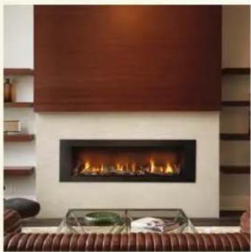
natural_image
Interior view of a modern living room featuring a dark gas stove with visible flames and a wooden backrest (no text or symbols)
natural_image
Exterior view of a modern stainless steel barbecue grill parked on a stone patio with residential houses in the background (no signage or text visible)
natural_image
Interior view of a modern kitchen with a washing machine and a large washing machine (no visible text or symbols)
24 Napoleon Road, Barrie, Ontario, Canada L4M 0G8
214 Bayview Drive, Barrie, Ontario, Canada L4N 4Y8
103 Miller Drive, Crittenden, Kentucky, USA 41030
De Riemsdijk 22, 4004 LC Tiel, The Netherlands
Phone: 1-866-820-8686
napoleon.com

MANUEL D'INSTALLATION
CONSIGNES DE SÉCURITÉ
▲ AVERTISSEMENT!
RISQUE D'INCENDIE OU D'EXPLOSION
natural_image
Technical line drawing of a mechanical enclosure or enclosure with internal compartments and mounting brackets (no text or symbols)POUR USAGE INTÉRIEUR SEULEMENT
CERTIFIÉ SELON LES NORMES NATIONALES CANADIENNES ET AMÉRICANES: CSA 2.22 ET ANSI Z21.50 POUR LES APPAREILS À GAZ DÉCORATIF À ÉVACUATION

BARRIER


PLACER L'ÉTIQUETTE DE NUMÉRO DU SÉRIE SUR LE MANUEL DU PROPRIÉTAIRE
Wolf Steel Ltd., 24 Napoleon Rd., Barrie, ON, L4M 0G8 Canada / 103 Miller Drive, Crittenden, Kentucky, USA, 41030
Téléphone 1(866)820-8686 • www.napoleon.com • hearth@napoleon.com
! AVERTISSEMENT

CERTIFIED www.nficertified.org
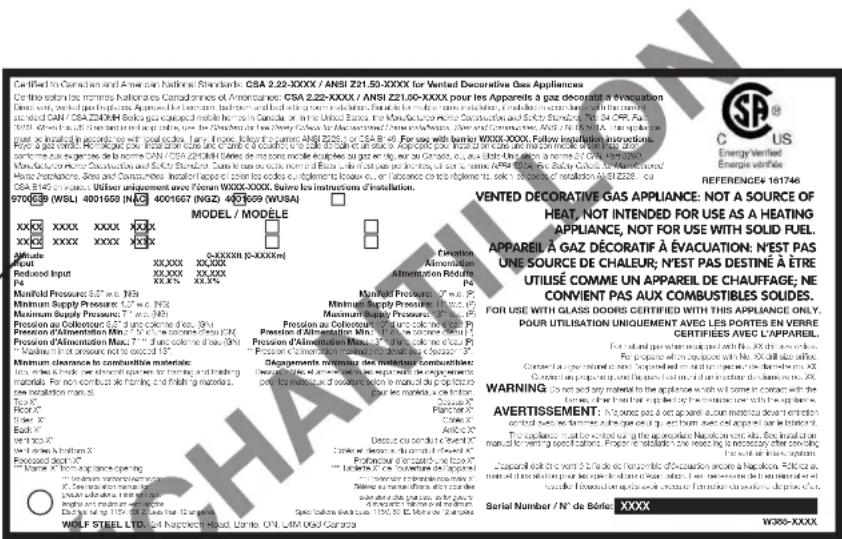
note:
Vue du côté droite
![1/2" [13mm] 33 1/8" [841mm] 4 1/2" [115mm] 6 1/4" [158mm] 18 5/16" [465mm]](/content/2026/04/732729/images/1aab7ff4f24a34fc2e07ad52c1d5ab96df339c5d663818d440fb7ee6cd089096.jpg)
| BLX42 BLX46 BLX56 | |||
| A | 4" (102mm) 4" (102mm) 5" (127mm) | ||
| B | 7" (178mm) 7" (178mm) 8" (203mm) | ||
| C | 18 3/4" (476mm) 22 3/4" (578mm) 32 3/4" (832mm) | ||
| D | 38 1/2" (978mm) 42 1/2" (1080mm) 52 1/2" (1334mm) | ||
| E | 42" (1067mm) 46" (1168mm) 56" (1422mm) | ||
natural_image
Mechanical assembly diagram showing a cylindrical component being inserted into a ring with a tool (no text or symbols)natural_image
Technical line drawing of a mechanical component with no visible text or symbolsX3
3
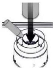
natural_image
Mechanical assembly diagram showing a tool interacting with a central component (no text or symbols visible)UTILISEZ SILICONE D'HAUTE TEMPÉRATURE POUR SCELLER L'ADAPTATEUR À L'APPAREIL COLLIERS.
4
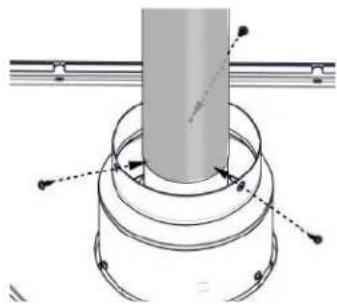
natural_image
Technical diagram of a mechanical assembly with concentric rings and a central shaft (no text or symbols)X3
5
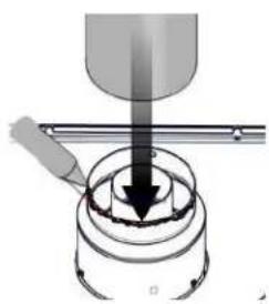
natural_image
Mechanical assembly diagram showing a tool interacting with a cylindrical component (no text or symbols visible)UTILISEZ SILICONE D'HAUTE TEMPÉRATURE POUR SCELLER L'ADAPTATEUR À L'APPAREIL COLLIERS.
6
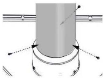
natural_image
Pure mechanical diagram showing a cylindrical component with curved arrows indicating motion or force direction (no text or symbols)X3
$$ H _ {F} = H _ {1} + H _ {2} = 2, 5 \mathrm{pi(0,8m)} + 2 \mathrm{pi(0,6m)} = 4, 5 \mathrm{pi(1,4m)} $$
$$ H _ {0} = 0, 0 3 \left(\text { deux } 9 0 ^ {\circ} \text { elbows } - 9 0 ^ {\circ}\right) = 0, 0 3 \left(1 8 0 ^ {\circ} - 9 0 ^ {\circ}\right) = 5, 4 \text { pi } (1, 7 m) $$
$$ H _ {T} = H _ {R} + H _ {D} = 4, 5 \text { pi } (1, 4 \mathrm{m}) + 5, 4 \text { pi } (1, 6 \mathrm{m}) = 9, 9 \text { pi } (3 \mathrm{m}) $$
$$ H _ {T} + V _ {T} = 9, 9 \text { pi } (3 m) + 1 1 \text { pi } (3, 4 m) = 2 0, 9 \text { pi } (6, 4 m) $$
Formule 1: H_T ≤ V_T
$$ 9. 9 \text { pi } (3 m) < 1 1 \text { pi } (3, 4 m) $$
Formule 2: H_T + V_T ≤ 40 pi (12,2m)
$$ 2 0, 9 \text { pi } (6, 4 \mathrm{m}) < 4 0 \text { pi } (1 2, 2 \mathrm{m}) $$

natural_image
Line drawing of a robotic arm mounted on a table (no text or symbols)H_1=3 P I(0,9m)
H_2=5 P I(1,5m)
H_R=H_1+H_2=3P(0,9m)+5P(1,5m)=8P(2,4m)
H_0=0.03 (deux coudes 90^-90^ ) = 0,03 ( 180^-90^ ) = 2,7PI (0,8m)
H_T=H_B+H_0=8 PI(2,4m)+2,7 PI(0,8m)=10,7 PI(3,3m)
H_T + V_T = 10,7 PI (3,3m) + 6PI (1,8m) = 16,7 PI (5,1m)
Formule 1: H T ≤ 4,2 VT
$$ 4, 2 \mathrm{V} _ {\mathrm{T}} = 4, 2 \mathrm{PI} (1, 3 \mathrm{m}) \times 6 \mathrm{PI} (1, 8 \mathrm{m}) = 2 5, 2 \mathrm{PI} (7, 7 \mathrm{m}) $$
Formule 2: H T + VT ≤ 24,75 PI (7,5m)
$$ 1 6, 7 \mathrm{PI} (5, 1 \mathrm{m}) \leq 2 4, 7 5 \mathrm{PI} (7, 5 \mathrm{m}) $$
V_1=4 P I(1,2m)
V_2=1,5 PI(0,5m)
VT = V1 + V_2 = 4PI(1,2m) + 1,5PI(0,5m) = 5,5PI(1,7m)
H_1=2 PI (0,6m)
H_2=1 P I(0,3m)
H_3=1 P I(0,3m)
natural_image
Line drawing of a cylindrical mechanical component mounted on a base, with no visible text or symbols.area
| X | Y | |---|---| | 0 | 40 | | 1.5 | 3 | | 3.1 | 10 | | 4.6 | 20 | | 6.1 | 20 | The chart displays a shaded triangular region bounded by two diagonal lines. The top-left corner contains the coordinate (X, Y) coordinates: (0,40), (12,40), and (20,20). The bottom-left corner contains the coordinate (X, Y) coordinates: (0,3) and (1.5). The right side of the triangle is also labeled with its corresponding coordinate values.H_1=8 i(2,4m)
H_2=2,5(0,8m)
H_1 = H_1 + H_2 = 8 pi (2,4m) + 2,5 pi (0,8m) = 10,5 pi (3,2m)
H_b=0.03 (four 90^ elbows -90^ )
$$ = 0, 0 3 (3 6 0 ^ {\circ} - 9 0 ^ {\circ}) = 8, 1 \text { pi } (2, 5 \mathrm{m}) $$
H_r = H_B + H_O = 10,5 pi(3,2 ~m) + 8,1 pi(2,5 ~m) = 18,6 pi(5,7 ~m)
H_t + V_t = 18,6 pi (5,7m) + 21 pi (6,4m) = 39,6 pi (12,1m)
Formule 1: H ≤ V_T
$$ 1 8, 6 \mathrm{pi} (5. 7 \mathrm{m}) < 2 1 \mathrm{pi} (6, 4 \mathrm{m}) $$
Formule 2: H T + VT ≤ 40 pi (12,19m)
$$ 3 9, 6 \text { pi } (1 2, 1 \mathrm{m}) < 4 0 \text { pi } (1 2, 2 \mathrm{m}) _ {-} $$
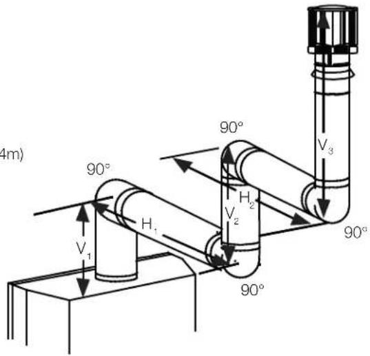
| BLX42 BLX46 | BLX56 | ||
| A | 18 9/16" (471mm) | ||
| B | 42 1/2" (1080mm) 47 | 3/8" (1203mm) 56 | 1/2" (1435mm) |
| C | 41 1/8" (1045mm) 44" | (1118mm) 51" | (1295mm) |
| D | 58 1/4" (1480mm) 62 | 1/4" (1581mm) 72 | 1/4" (1835mm) |
| E | 6" (152mm) | ||
natural_image
Isometric line drawing of a two-panel wall assembly with labeled components A and B (no text or symbols beyond labels)| BLX42 BLX46 | BLX56 | ||
| A | 18 9/16” (471mm) | ||
| B | 42 1/2” (1080mm) | 47 3/8” (1203mm) | 56 1/2” (1435mm) |
5.0 installation d'évacuation

AVERTISSEMENT
5.2 installation verticale
natural_image
Close-up of metallic cylindrical components with textured surfaces and a textured surface (no visible text or symbols)natural_image
Diagram showing a device panel with an inset close-up view of its internal components (no text or symbols visible)INSTRUCTIONS D'ALLUMAGE
note:
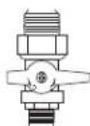
MANUAL SHUT-OFF
(SHOWN IN OFF POSITION)
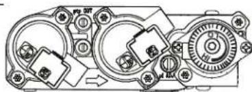
natural_image
Mechanical assembly diagram showing interconnected gears and housing components (no text or labels)COUPEZ L'ALIMENTATION DE GAZ
natural_image
Black handheld electronic device with a small screen and control buttons, labeled (Fig. 1) at the bottom (no other text or symbols visible)(Fig. 2) (Fig. 3)
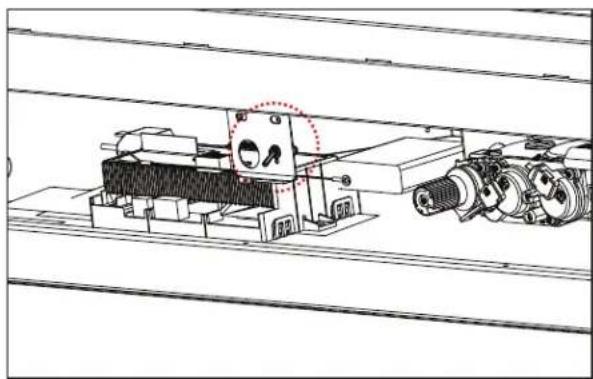
natural_image
Technical line drawing of a mechanical assembly with rollers and housing (no text or symbols)Opératisature fini
FR
9.1 installation des supports de fixation
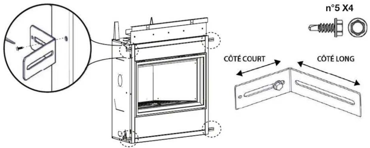
natural_image
Technical line drawing of a mechanical assembly with mounting brackets and a vertical support (no text or symbols)note:
| BLX42 | BLX46 | BLX56 | |
| F | 39 3/8" (1000mm) | ||
| A | 18 9/16" (471mm) | ||
| B | 42 1/2" (1080mm) | 47 3/8" (1203mm) | 56 1/2" (1435mm) |
| H | 84" (2130mm) | ||
| I | 3 1/2" (89mm) | ||
natural_image
Diagram of a reclining human figure inside a rectangular frame (no text or labels)natural_image
Diagram of a mechanical component with two irregular shapes inside a transparent frame (no text or symbols)natural_image
Illustration of a whale-like creature inside a transparent enclosure (no text or symbols)natural_image
Simple line drawing of a bed with two legs stacked, enclosed in a rectangular frame (no text or symbols)natural_image
Diagram of a mechanical or architectural component with layered structure and measurement indicators (no text or symbols)natural_image
Illustration of a reclining animal in a storage tray (no text or symbols)natural_image
Illustration of a fossilized dinosaur-like creature with visible tail feathers and segmented body (no text or symbols)natural_image
Diagram of a biological structure with layered components and supporting elements (no text or labels)natural_image
Abstract diagram of irregular gray shapes on a light background, no text or symbols presentnatural_image
Diagram showing airflow or ventilation through a window frame with an inset magnified view of the wall (no text or symbols)10.3 installation de la garniture de finition
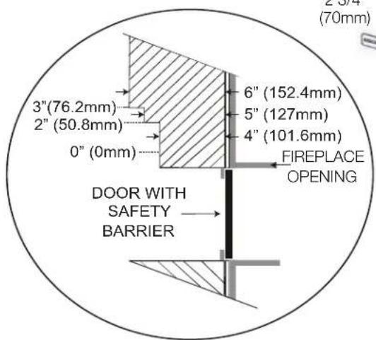
natural_image
Technical line drawing of a mechanical device with an inset close-up showing a window detail (no text or symbols)natural_image
Technical line drawing of a multi-level storage or rack system with an inset showing internal components (no text or symbols)natural_image
Technical line drawing of a structural frame with supports and directional arrows, labeled (Fig. 1) (no text or symbols on the diagram itself)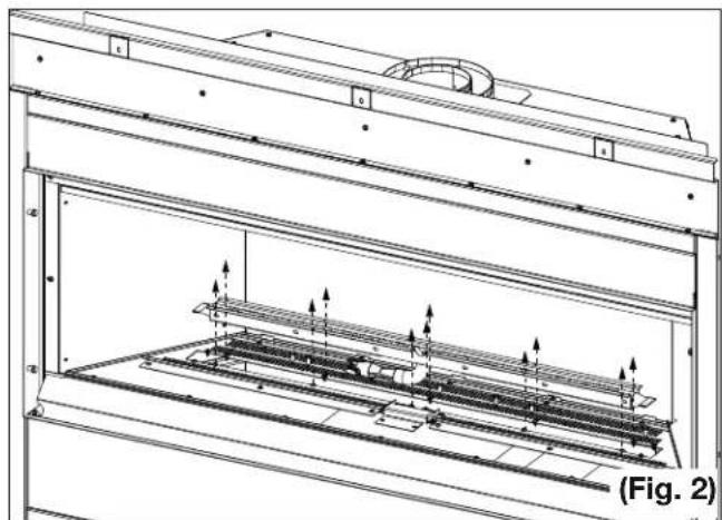
natural_image
Technical line drawing of a mechanical assembly with internal components and mounting brackets (no text or symbols)finitions
natural_image
Technical line drawing of a mechanical assembly with internal components and mounting brackets (no text or symbols)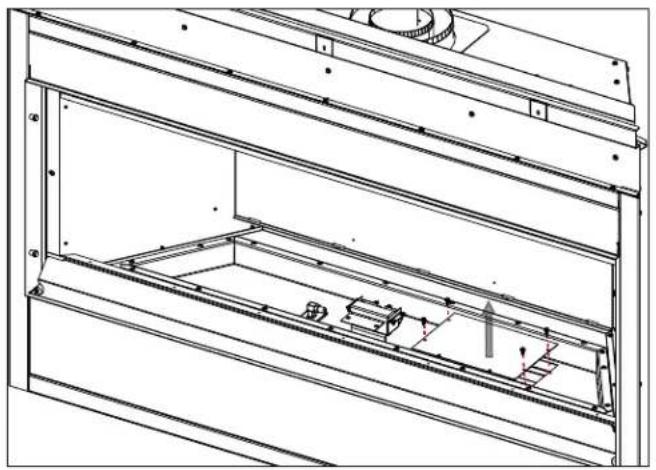
natural_image
Technical line drawing of a mechanical assembly with internal components and mounting brackets (no text or symbols)(Fig. 3) (Fig. 4)
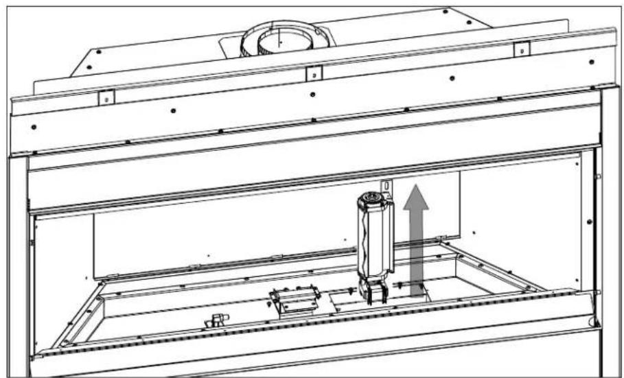
natural_image
Technical line drawing of a mechanical assembly inside a frame, showing internal components and a central cylindrical component with an upward arrow (no text or symbols)(Fig. 5)
11.0 ajustements
FR
3/8" - 1/2" (9,5mm - 12,7mm)
natural_image
Simple line drawing of a laboratory setup with test tubes and a funnel, no text or symbols present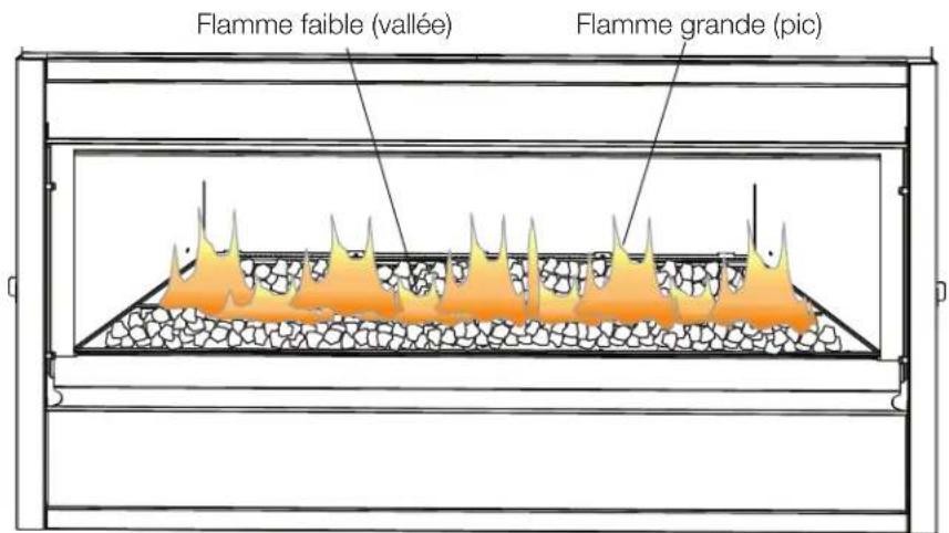
pièces de rechange
BLKBLP56 illustrated
DLKBLP56 illustrated
natural_image
Modern gas stove with visible flames in a living room (no text or symbols)
natural_image
Exterior view of a modern stainless steel grill with open doors, situated in front of residential houses and stone pavement (no signage or text visible)
natural_image
Interior view of a modern kitchen with a washing machine and a large washing machine (no visible text or symbols)
24 Napoleon Road, Barrie, Ontario, Canada L4M 0G8
214 Bayview Drive, Barrie, Ontario, Canada L4N 4Y8
103 Miller Drive, Crittenden, Kentucky, USA 41030