AL 2 S - Exercise bike Christopeit - Free user manual and instructions
Find the device manual for free AL 2 S Christopeit in PDF.

User questions about AL 2 S Christopeit
0 question about this device. Answer the ones you know or ask your own.
Ask a new question about this device
Download the instructions for your Exercise bike in PDF format for free! Find your manual AL 2 S - Christopeit and take your electronic device back in hand. On this page are published all the documents necessary for the use of your device. AL 2 S by Christopeit.
USER MANUAL AL 2 S Christopeit
Assembly and operating instructions
Order No.: 2495-2497 GB
Page: 16-27

natural_image
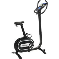
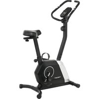
Exterior view of a white exercise bike with black and silver body, no visible text or symbols on the device itself.AL2 S - Silber - 2497 AL2 S - Black - 2495
natural_image
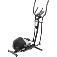
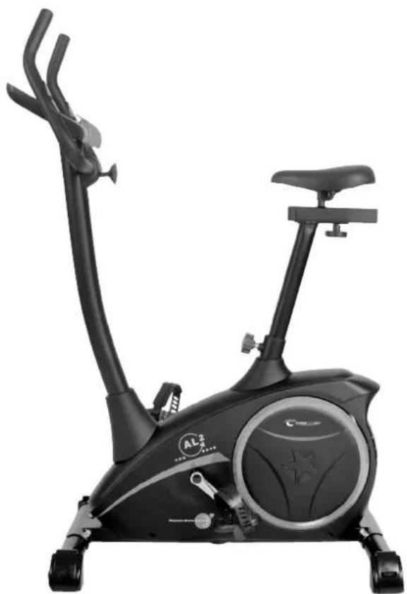
Black exercise bike with visible aerodynamic control panel and logo (no text or symbols on body)INHALTSÜBERSICHT
InhaltSeite
2 Christopeit-Sport Community
text_image
Technical diagram of an exercise machine with numbered components and labeled parts in ChineseMONTAGEANLEITUNG
text_image
Technical diagram of a mechanical device with numbered components for identificationSCHRITT 3
Montage der Pedalen (22L+22R) an den Pedalarmen (21L+21R).
text_image
Technical diagram of a stationary exercise machine with numbered components for identification.
text_image
Technical diagram of a stationary exercise machine with numbered components and an inset close-up view highlighting key parts.SCHRITT 6
text_image
Technical diagram of a stationary exercise bike with numbered components and labeled parts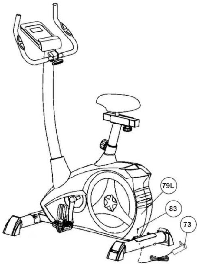
text_image
Technical line drawing of a stationary exercise bike with labeled components including 79L, 83, and 73 parts.natural_image
Line drawing of a stationary exercise machine with rotating legs and arm (no text or symbols)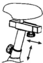
Aufsteigen
natural_image
Technical line drawing of a stationary exercise machine inside a transparent enclosure, showing front and side views (no text or symbols)natural_image
Line drawing of a stationary exercise machine inside a transparent cube, with dimension annotations (1560, 1790) and page number 2200 (no text or symbols on the device itself)other
| TIME | P7 | P | P8 | P9 | P10 | |---|---|---|---|---|---| | 0:00 | 0 | 0 | 0 | 0 | 0 | | INTL. | KM | LEVEL | INTL. | KM | 0 | | 0:00 | 0 | 9 | 0 | 9 | 0 | | INTL. | 0 | 0 | 0 | 0 | 0 | | 0:00 | 0 | 0 | 0 | 0 | 0 | | 0:00 | 0 | 0 | 0 | 0 | 0 | | INTL. | 0 | 0 | 0 | 0 | 0 | | 0:00 | 0 | 0 | 0 | 0 | 0 | | INTL. | 0 | 0 | 0 | 0 | 0 | | 0:00 | 0 | 0 | 0 | 0 | 0 | | INTL. | 0 | 0 | 0 | 0 | 0 |
P11 - P15: indiv. Trainingsprogramme (U1-U5)
text_image
TIME 000 RUT. 00 00 000 P 11 U 1 TIME P RUT. 00 00 WART 0 TIME P 12 U 2 TIME P RUT. 00 00 WART 0 TIME P 13 U 3 TIME P RUT. 00 00 WART 0 TIME P 14 U 4 TIME P RUT. 00 00 WART 0 TIME P 15 U 5 TIME P RUT. 00 00 WART 0 TIMEP16: Watt-Programm
natural_image
Sequence of four sequential illustrations showing a person performing a stretching or kneeling movement (no text or symbols)16 Important recommendations and safety instructions
17-18 Assembly instructions
20 Use of the device
20 RPM and power level
21-23 Computer
23 Kinomap app
24 Cleaning, checks and storage
24 Troubleshooting
25 General training instructions
26-27 Parts list – Spare parts list
66-67 Exploded drawing
We congratulate you on your purchase of this home training sports unit and hope that we will have a great deal of pleasure with it. Please take heed of the enclosed notes and instructions and follow them closely concerning assembly and use. Please do not hesitate to contact us at any time if you should have any questions.
IMPORTANT RECOMMENDATIONS AND SAFETY INSTRUCTIONS
Our products are TÜV-GS tested and therefore represent the highest current safety standards. However, this fact does not make it unnecessary to observe the following principles strictly.
-
Assembly the machine exactly as described in the installation instructions and use only the enclosed, specific parts of the machine. Before assembling, verify the completeness of the delivery against the delivery notice and the completeness of the carton against the assembly steps in the installation and operating instructions.
-
Before the first use and at regular intervals (approximately every 50 Operating hours) check the tightness of all screws, nuts and other connections and the access shafts and joints with some lubricant so that the safe operating condition of the equipment is ensured. In particular, the adjustment of saddle and handlebar need smooth function and good condition.
-
Set up the machine in a dry, level place and protect it from moisture and water. Uneven parts of the floor must be compensated by suitable measures and by the provided adjustable parts of the machine if such are installed. Ensure that no contact occurs with moisture or water.
-
Place a suitable base (e.g. rubber mat, wooden board etc.) beneath the machine if the area of the machine must be specially protected against indentations, dirt etc.
-
Before beginning training, remove all objects within a radius of 2 metres from the machine.
-
Do not use aggressive cleaning agents to clean the machine and employ only the supplied tools or suitable tools of your own to assemble the machine and for any necessary repairs. Remove drops of sweat from the machine immediately after finishing training.
-
Attention! Systems of the heart frequency supervision can be inexact. Excessive training can lead to serious health damage or to the death. Consulta doctor before beginning a planned training programme. He can define the maximum exertion (pulse, Watts duration of training etc.) to which you may expose yourself and can give you precise information on the correct posture during training, the targets of your training and your diet. Never train after eating large meals. This item is not suitable for therapeutically purposes!
-
Only train on the machine when it is in correct working order. Use original spare parts only for any necessary repairs. Attention! Replace the worm parts immediately and keep this equipment out of use until repaired.
-
When setting the adjustable parts, observe the correct position and the marked, maximum setting positions and ensure that the newly adjusted position is correctly secured.
-
Unless otherwise described in the instructions, the machine must only be used for training by one person at a time. The exercise time should not overtake 60 min/daily.
-
Wear training clothes and shoes which are suitable for fitness training with the machine. Your clothes must be such that they cannot catch during training due to their shape (e.g. length). Your training shoes should be appropriate for the trainer, must support your feet firmly and must have non-slip soles.
-
Attention! If you notice a feeling of dizziness, sickness, chest pain or other abnormal symptoms, stop training and consult a doctor.
-
Never forget that sports machines are not toys. They must therefore only be used according to their purpose and by suitably informed and instructed persons.
-
People such as children, invalids and handicapped persons should only use the machine in the presence of another person who can give aid and advice. Take suitable measures to ensure that children never use the machine without supervision. Ensure that the person conducting training and other people never move or hold any parts of their body into the vicinity of moving parts.
-
It must be ensured that the user and other people never go or stand with any body parts in the area of still moving parts.
-
At the end of its life span this product is not allowed to dispose over the normal household waste, but it must be given to an assembly point for the recycling of electric and electronic components. You may find the symbol on the product, on the instructions or on the packing. The materials are reusable in accordance with their marking. With the re-use, the material utilization or the protection of our environment. Please ask the local administration for the responsible disposal place.
-
To protect the environment, do not dispose of the packaging materials, used batteries or parts of the machine as household waste. Put these in the appropriate collection bins or bring them to a suitable collection point.
-
For speed dependent operation mode, the braking resistance level can be adjustable manually and the variations of power will depend on the pedaling speed. For speed independent operation mode, the user can set wanted power consumption level in Watt, constant power level will be kept by various braking resistance levels, that will be determined automatically by system. That is independent on the pedaling speed.
-
The unit has a resistance device with 24 levels. This makes it possible to increase or reduce the braking resistance and thus the amount of effort required in the training. Pressing the button with “-” reduces the braking resistance and thus the amount of effort required in the training. Pressing the button “+” increases the braking resistance and thus the amount of effort required in the training.
-
This machine has been tested in compliance with wird EN ISO 20957-1:2014 and EN ISO 20957-5:2016 „H/A“. The maximum permissible load (=body weight) is specified as 150 kg. The classification of HA means this exercise bike is designed for home use only and with good accuracy class. The deviation tolerance is ±5W up to 50 watts and ±10% over 50 watts. This item's computer corresponds to the basic demands of the Directive of 2014/53/EU (RED).
-
The assembly and operating instructions is part of the product. If selling or passing to another person the documentation must be provided with the product.
-
This device may only be operated with the supplied power supply unit.
ASSEMBLY INSTRUCTIONS
Remove all the separate parts from the packaging, lay them on the floor and check roughly that all are there on the base of the assembly steps. Please note that a number of parts have been connected directly to the main frame and preassembled. In addition, there are several other individual parts that have been attached to separate units. This will make it easier and quicker for you to assemble the equipment. Assembly time: 30 - 40 min.
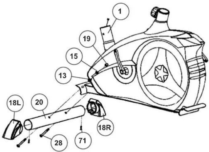
STEP 1
Attach the stabilizer (20) at main frame (1).
- Put the end caps with transportation roller (18L+18R) at the ends of shorter front foot (20) in appropriate position and screw them tightly by using screw (71).
- Attach the front foot (20) with the preassembled end caps with transportation rollers (18) to the main frame (1). Do this with the two screws (28), washers (13), spring washers (15) and cap nuts (19).
STEP 2
Attach the stabilizer (27) at main frame (1).
- Put the end caps with height adjustment (26) at the ends of longer rear foot (27) and screw them tightly by using screw (71).
- Mount the rear foot (27) on the base frame (1) so that the end caps stand properly on the floor. Do this with the two screws (28), washers (13), spring washers (15) and cap nuts (19). After assembly has been completed, you can compensate for minor irregularities in the floor by turning the wheel at cap (26). The equipment should be set up that the equipment does not move of its own accord during a training session. If you like to change the position of the home bike, put one foot in front of the front foot (20) and pull at handlebar in front direction until the home bike can move easy on the transportation rollers to another place.
STEP 3
Attach the pedals (22L+22R) at pedal crank (21L+21R).
- Screw the right pedal (22R) into the pedal arm (21R), which is on the right-hand side in the cycling direction. (Attention! the screw direction is clockwise).
- Screw the left pedal (22L) into the pedal arm (21L) on the left hand side in the cycling direction. (Attention! the screw direction is anti-clockwise.) The assignment of the individual parts has been simplified for you by an additional marking with the letter R for right and L for left.
- Then mount the pedal straps (89L+89R) left and right on the associated pedals (22L+22R).
text_image
1 19 15 13 18L 20 28 71 18R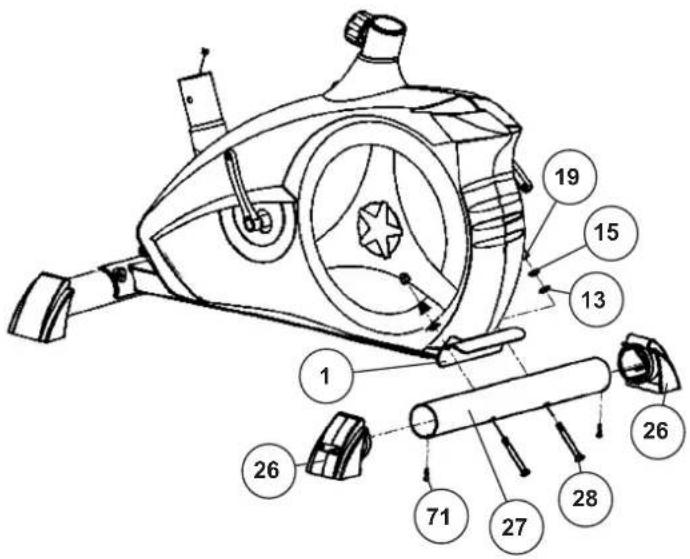
text_image
Technical diagram of a helicopter with numbered parts for identification and assembly reference.
text_image
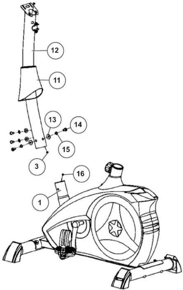
22L 89L 21L 22R 21R 89RSTEP 4
Attach the front post (12) at main frame (1).
- Slide the handlebar support cover (11) onto the handlebar support (12).
- Hold the handlebar support (12) with the computer cable (3) against the main frame holder. Connect the plug for the computer cable (3) coming out of the bottom of the handlebar support (12) of the computer with the matching plug for the motor cable (16) coming out of the main frame (1). Note: The computer cable harness (3) projecting from the support (3) must not slide into the tube, as it is required for later steps of installation.)
- Place the handlebar support (12) in the locator provided for it in the main frame (1). Ensure that the cable connections made in step 3 are not squashed. When putting the steering tube in place, push the former slowly down into the locator in the main frame. Screw the handlebar support (12) onto the base frame (1) with the screws (14), spring washers (15) and washers (13).
- Push the handlebar support cover (11) into right position to cover up the screw connection point.
STEP 5
Attach the saddle (34) and saddle slide (33) at saddle support (29) and the saddle support (29) at main frame (1).
- Push the saddle (34) with saddle bracket into the saddle slide (33) and tight it up in desired position. To do this, both black nuts must be tightened very firmly.
- Place the saddle slide (33) into the holder of saddle support (29), set it at the desired horizontally position and screw it onto the saddle support (29) by fixing piece (6) washer (32) and star grip nut (31).
- Push the saddle support tube (29) into the matching locator in the main frame (1), set it at the desired position and lock it by inserting the bolt with the quick release (30) in place and doing it up tight. (Note: To screw in the rapid-action lock (30), the threaded hole in the main frame (1) and one of the holes in the saddle support (29) must be aligned. Furthermore, ensure that the saddle support (29) is not pulled out of the main frame beyond the marked maximum Position. The setting of the saddle post can be adjusted as desired later. For this, the rapid action catch (30) must be loosened by only a few revolutions, the cap of the lock must be pulled away and the saddle adjusted. Then secure the new setting by tightening the rapid action catch.) Furthermore, you must ensure when setting this desired position that the seat pillar is not pulled out of the main frame further than the highest setting position, which is marked. Attention! Ensure before every exercising that the saddle is tighten firmly.
text_image
Technical diagram of a stationary exercise machine with numbered components for identification.
text_image
Technical diagram of a stationary exercise machine with numbered components and an inset close-up view highlighting key parts.STEP 6
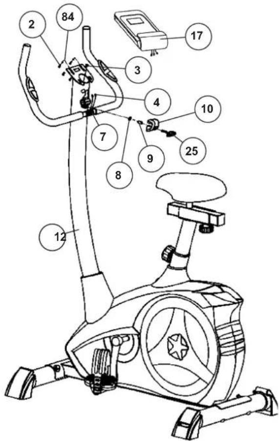
Attach the handlebar (7) and computer (17) at handlebar support (12).
- Guide the handlebar (7) to the open handlebar mount on the support tube (12) and then close the handlebar mount over the handlebar (7). Then thread the two pulse cables up through the openings on the support tube
- Attach the handlebar cover (10) at the handlebar holder.
- Screw the handlebar (7) in desired position at the handlebar post (12) with spacer (9), washer (8) and handlebar screw (25).
- Push the plugs of the connecting cable (3) and pulse cable (4) projecting from the handlebar support (12) into the associated socket of the computer (17). The pulse cables have the same plug connections and therefore no specific assignment is necessary.
- Place the computer (17) on the top of the handlebar support tube (12) without squeezing the cables and tight firmly by using screw (2) and washers (84). The screws (2) you find at backside of computer.
text_image
Technical diagram of a stationary exercise bike with numbered components and labeled partsSTEP 7
Attach the power.
- Please insert the plug of adaptor (73) to the power plug (83) at end of chain guard (79L).
- Please insert the plug of adaptor (73) to the jack of wall power (230V\~50Hz).
CHECKS
- Check the correct installation and function of all screwed and plug connections. Installation is thereby complete.
- When everything is in order, familiarize yourself with the machine at a low resistance setting and make your individual adjustments.
Note:
Please keep the tool set and the instructions in a safe place as these may be required for repairs or spare parts orders becoming necessary later.

text_image
79L 83 73USE OF THE DEVICE
Adjustment – Seat Position
For an effective workout, the seat must be adjusted properly. While your are pedaling, your Knees should be slightly bent when the pedals are in the farthest position. In order to adjust the seat, unscrew the knob few turns and draw it out slightly. Adjust the seat to the right height, then release the knob and tighten it all the way.
Attention! Make sure to put the knob back into place in the seat post and tighten it completely. Never exceed the maximum height of the seat. Always get off the bicycle before making any adjustment.
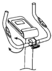
Handlebar adjustment
To adjust the handlebar, simply loosen the handlebar screw until the handlebar can be brought into the desired position and tighten it again after adjustment.
natural_image
Line drawing of a stationary exercise machine with rotating arms and legs (no text or symbols)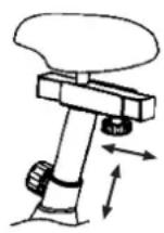
Mount
After the seat is adjusted to properly position, insert your foot into retaining strap of pedal step on the pedal and hold the handlebar tightly. Try to put whole body weight on your foot and simultaneously cross over the trainer and land your another foot on the other side. Now you are in the position to start your training.
Use
Keep you hands on the handlebar, and both feet are insert into retaining straps of both pedal properly. Pedal your exercise bike by your both feet alternately. Then you can increase the pedaling speed gradually and adjust braking resistance levels to increase the exercise intension.
Dismount
Slow down the pedaling speed until it comes to rest. Keep the left hand grabbing the left handlebar tightly, put your feet cross over the equipment and land on the floor, then land the other one.
Transportation
There are two rollers equipped on the front foot. For moving, you can lift up the rear foot and drive it to where you would like to locate or store it.
This training equipment is a stationary exercise machine used to simulate without causing excessive pressure to the joints, hence decreasing the risk of impact injuries.
Exercise bike offer a non-impact cardiovascular workout that can vary from light to high intensity based on the resistance preference set by the user. It will strengthen your muscles of legs and increase cardio capacity and maintain fitness of your body also.
RPM AND POWER LEVEL

| RPM → Level ↓ | 20 30 40 | 50 60 70 | 80 90 100 | |||||
| 1 | 7 15 24 | 34 46 61 | 74 90 111 | |||||
| 2 | 8 16 26 | 37 50 67 | 82 100 124 | |||||
| 3 | 9 18 31 | 45 60 80 | 98 120 146 | |||||
| 4 | 10 22 36 | 52 70 98 | 114 140 168 | |||||
| 5 | 11 24 40 | 59 80 107 | 131 160 192 | |||||
| 6 | 13 27 45 | 66 90 121 | 148 160 216 | |||||
| 7 | 14 30 50 | 74 100 134 | 166 202 241 | |||||
| 8 | 15 33 55 | 81 110 147 | 183 223 266 | |||||
| 9 | 17 36 60 | 89 120 161 | 201 244 291 | |||||
| 10 | 18 39 65 | 97 130 175 | 219 266 315 | |||||
| 11 | 20 42 70 | 104 140 189 | 237 289 340 | |||||
| 12 | 21 44 75 | 111 150 202 | 254 310 365 | |||||
| 13 | 22 47 80 | 118 160 215 | 270 330 390 | |||||
| 14 | 23 50 85 | 125 170 230 | 286 350 414 | |||||
| 15 | 25 52 90 | 133 180 243 | 302 369 438 | |||||
| 16 | 26 55 94 | 140 190 256 | 318 389 462 | |||||
| 17 | 27 58 99 | 146 200 269 | 334 408 486 | |||||
| 18 | 28 61 104 | 153 210 | 282 350 426 510 | |||||
| 19 | 30 64 109 | 161 220 | 295 365 446 534 | |||||
| 20 | 31 67 114 | 169 230 | 382 464 558 | |||||
| 21 | 32 70 118 | 176 240 | 321 398 484 580 | |||||
| 22 | 34 72 122 | 182 250 | 334 414 506 602 | |||||
| 23 | 35 74 127 | 189 260 | 347 430 526 625 | |||||
| 24 | 37 76 131 | 196 270 | 361 446 548 649 |
Remarks:
The power consumptions (Watt) are adjusted by measuring the driving speed (min-1) of axle and the braking torque (Nm). Your equipment was tested to fulfill the requirements of its accuracy classification before shipment. If you have doubts about the accuracy, please contact with your local retailer or send it to accredited test laboratory to ensure or calibrate it. (Please note that a deviation tolerance as noted on page 16, is permissible.)
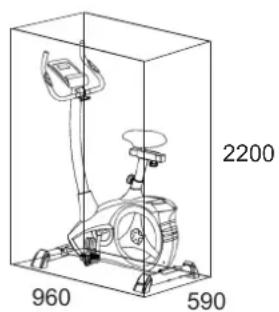
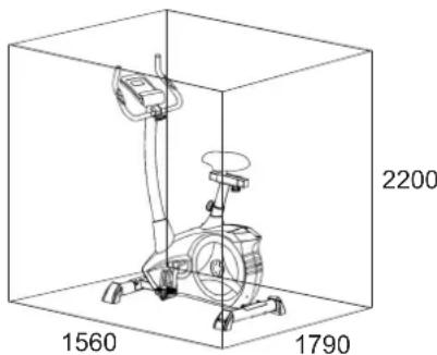
TRAINING SPACE REQUIREMENT
natural_image
Technical line drawing of a stationary exercise machine inside a transparent enclosure, showing labeled dimensions (960, 590) and a page number 2200 (no text or symbols on the device itself)Training area in mm
(for home trainer and user)

text_image
2200 1560 1790Free area in mm
(Training area and security area (circulating 600mm))

text_image
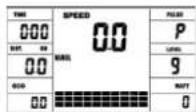
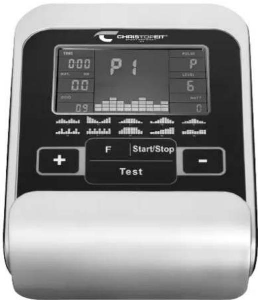
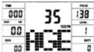
CHRISTOPERT SWEET POWER TIME 0:00 DIST. AW 0.0 0:00 0:9 P1 PULSE LEVEL 6 WATT 0 F Start/Stop TestFUNCTION
The computer is very easy to use. By displaying all functions at the same time, there is no need to switch back and between the individual functions and you are always fully informed about your training process at a glance. This device is a speed-independent device. In order to achieve the performance you want, the computer regulates the resistance independently of the cadence in the watt program P16.
Turn on: Insert the connection plug into the power supply socket on the device. An acoustic signal sounds - all LCD display segments appear for 2 seconds and are set to 00. or
The power plug is already in the socket / device has automatically switched off. By pressing any key - or with at least one turn of the pedal - the computer switches itself on.
Turn off: As soon as the device is not used for more than approx. 4 minutes, the computer switches off automatically. After finishing the training, unplug the power supply unit from the socket.
KEYS
[Start/Stop] key: Training start or interruption in the selected program. The computer only starts counting when the [Start/Stop] key has been pressed before. If the [Start/Stop] key is pressed for more than 3 seconds, all values are reset to 00:00 in the starting position.
[F] key: You can switch from one input field to the next with the input and confirmation key [F]. The selected function flashes. Enter the values with the [+/-] keys and confirm them by pressing the [F] key again. At the same time, the flashing display jumps to the next input field. During training, the functions UPM
and calories, as well as speed and distance can be displayed permanently or alternately by pressing the [F] key. If the [F] key is pressed for more than 3 seconds, all values are reset to 00:00 in the starting position.
[+/-] keys: Use the [+/-] keys to change the values - only flashing values information can be changed in value.
[Test] key: With this key you can determine your fitness grade.
DISPLAY
[P1-21] Program: Display of set program 1-21. (Manual; P1 - P10 = fitness program; P11-P15 = individual user program; P16 = watt program; P17-P20 = pulse program; P21 = body fat program)
[LEVEL] Resistance level: Display of the resistance from level 1-24. The higher the number, the higher the resistance. The bar graph hat 8 bars available. Each bar shows three values You can see the exact value on the [LEVEL] display. The resistance can be changed in every program except WATT program P16 by pressing the [+/-] keys.
[TIME] Time: For setting / displaying the time in minutes and seconds up to a maximum of 99:00 minutes. Preselection in minute steps / counting up + down in second steps. In the programs P1-P20 min. default time is set to 5 minutes. Setting range 5-99 min.
[WATT] Watt: The computer precisely measures the performance achieved during training. The performance displayed in watts. Setting range 10-300 watt. In program P16 consider the display of the target value.
[RPM] RPM / [SPEED] Speed: Display of pedal revolutions per minute and speed in km/h in automatic change. Or permanent by pressing the [F] key.
[DIST] Distance / [CAL] Calories: Display and default for distance and restrictions. The distance can be from 1 - 999 km. Using the average values, the computer calculates the calories that are displayed in KCal. To convert the binding unit of measurement for energy „Joule“ in the general target specification use this formulas: 1 Joule = 0.239 cal, or 1 cal = 4.186 J. The loss calories consumption can be set from 10 - 990 kcal. The up / down counting takes place in 0.1 steps. Display of distance and approx. calories alternating automatically. Or permanent by pressing the [F] key.
[ODO] KM Total: The distance in km of all training units is displayed. It is not possible to specify. The ODO display can be reset to zero at any time. To do this, press the [F] key and the [Start/Stop] key at once for 2 seconds.
[PULSE] Pulse display: The currently measured pulse is displayed here. If an upper heart rate limit is set, the display flashes when the set value is reached.
Pulse limit / Age: Available in programs P17-P20. Program P17-P19 are training programs with calculated max heart rate of 55% / 75% or 95%. As soon as you enter your age, the computer will calculate your max. pulse value that you should never exceed (formula: (220 - age) x 0.80). When this value is reached, the [PULSE] display starts to flash and you should then immediately reduce the speed or the load level. Age setting range: 10-100. In program P20: Display of the individual target heart rate you have specified. Pulse setting range: 60-240
Resistance profile: The desired training duration can be preset in the [TIME] display. The system divides this preset time into 10 sub-intervals. Each bar on the time axis (horizontal) = 1/10 of the specified time, e.g.: training time = 5 min = each bar is 30 seconds, training time = 10 min = each bar = 1 min. Each of the 10 bars corresponds to such a time interval. The current time bar is indicated by FLASHING. If no time is specified, each time bar means 3 minutes of training, ie after 3 minutes the flashing display jumps from bar 1 to bar 2, etc. up to a total of 30 minutes. If the program is stopped in the meantime with the [Start/Stop] key, the time to continue counting from there after pressing the [Start/Stop] key again.
Pedal resistance: You can use the [+/-] key to adjust the pedal resistance at any time - in all programs, except in the watt program P16. You can see the change in the height of the bar and in the [LEVEL] display - the higher the bar, the higher the resistance and contrariwise. Each bar segment stands for 3 levels (e.g. 3 segments stand for levels 7, 8 + 9 or 7 segments stand for levels 19, 20 + 21). The selected value is shown on the [LEVEL] display. The change affects the current and subsequent time position. The height of the bars indicates the load, not a terrain profile. Program sequences are shown graphically on the display. The individual programs run as shown in the bar diagram in the display field, e.g. program 5 = mountain program 2 = valley etc. (where the bar height = resistance, the time is distributed over the bar width)
After setting the program, it is essential to press the [Start/Stop] key if you want to start training. In principle, all determined and displayed values are not suitable for medical evaluations.
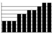
High bar = high pedal resistance Low beams = small pedal resistance Each bar segment contains 3 levels Each of the 10 time beams corresponds 1/10 of the given training time
PROGRAMMS
1. MANUAL: Manual program
This program corresponds to the functions of a normal exercise bike. The time, the speed, the rpm, the distance, the wattage, the Kcal and the current pulse are shown permanently in the display. The pedal resistance can be set manually using the [+/-] keys. All values are to be operated manually - there is none automatic regulation. Setting of the training parameters time / distance / calories / upper pulse limit by pressing the [F] key.
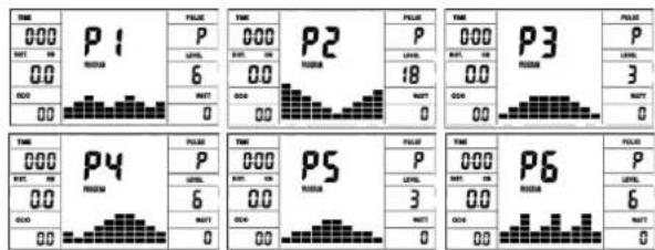
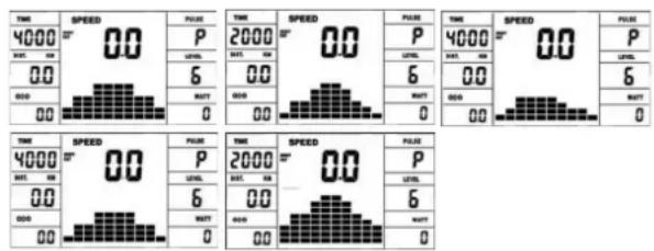
P1 - P10: Fitness programs
Various training programs are given here. If one of these programs is selected, the program runs automatically and includes various intervals. The division is made in difficulty levels and in time intervals. However, you can intervene in the program at any time to change the pedaling resistance or the duration. In addition, there is a corresponding bar display in the display field. Setting of the training parameters time / distance / calories / upper pulse limit by pressing the [F] key.
bar
| TIME | P1 | P2 | P3 | |---|---|---|---| | 000 | 6 | 18 | 3 | | 000 | 0 | 0 | 0 | | 000 | 6 | 3 | 6 | | 000 | 0 | 0 | 0 |
text_image
TIME 000 P7 PASE TIME P8 PASE TIME P9 PASE RUT. 4W LEVEL 000 P10 RASE LEVEL 9 000 P10 RASE LEVEL 4 00 9 00 9 00 DATA DATA DATA DATA DATA DATA DATA DATA DATA DATA DATA DATA DATA DATA DATA DATA DATA DATA DATA DATA DATA DATA DATA DATA DATA DATA DATA DATA DATA DATA DATA DATA DATA DATA DATA DATA DATA DATA DATA DATA DATA DATA DATA DATA DATA DATA DATA DATA DATA DATA DATA DATA DATA DATA DATA DATA DATA DATA DATA DATA DATA DATA DATA DATA DATA DATA DATA DATA DATA DATA DATA DATA DATA DATA DATA DATA DATA DATA DATA DATA DATA DATA DATA DATA DATA DATA DATA DATA DATA DATA DATA DATA DATA DATA DATA DATA DATA DATA DATA DATA DATA Data DATA DATA DATA DATA DATA DATA DATA DATA DATA DATA DATA DATA DATA DATA DATA DATA DATA DATA DATA DATA DATA DATA DATA DATA DATA DATA DATA DATA DATA DATA DATA DATA DATA DATA DATA DATA DATA DATA DATA DATA DATA DATA DATA DATA DATA DATA DATA DATA DATA DATA DATA DATA DATA DATA DATA DATA DATA DATA DATA DATA DATA DATA DATA DATA DATA DATA DATA DATA DATA DATA DATA DATA DATA DATA DATA DATA DATA DATA DATA DATA DATA DATA DATA DATA DATA DATA DATA DATA DATA DATA DATA DATA DATA DATA DATA DATA DATA DATA Data Data DATA DAILY 00 0 0 0 0 0 0 0 0 0 0 0 0 0 0 0 0 0 0 0 0 0 0 0 0 0 0 0 0 0 0 0 0 0 0 0 0 0 0 0 0 0 0 0 0 0 0 0 0 0 0 TIME 000 P7 PASE TIME P8 PASE TIME P9 PASE RUT. 4W LEVEL 000 P10 RASE LEVEL 9 000 P10 RASE LEVEL 9 000 P10 RASE LEVEL 9 000 P10 RASE LEVEL 9 000 P10 RASE LEVEL 9 000 P10 RASE LEVEL 9 000 P10 RASE LEVEL 9 000 P10 RASE LEVEL 9 000 P10 RASE LEVEL 9 00
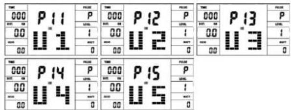
P11 - P15: indiv. training programs (U1-U5)
Here you can enter and train your various resistance profiles (U1-U5). Setting of the training parameters time/ distance/calories/ upper pulse limit by pressing the [F] key.
text_image
TIME 000 P 11 U 1 00 00 TIME P 1 00 P 12 U 2 00 00 TIME P 1 00 P 13 U 3 00 00 TIME P 14 U 4 00 P 15 U 5 00 P 1 00 P 16 U 6 00P16: Watt-Program
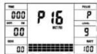
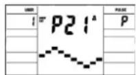
Here you can enter your individual watt specification. The pedaling resistance is automatically adjusted within a certain tolerance range by the computer, regardless of the pedaling frequency, so that you are always in the specified zone. Setting of the training parameters time / distance / calories / upper pulse / watt limit by pressing the [F] key.
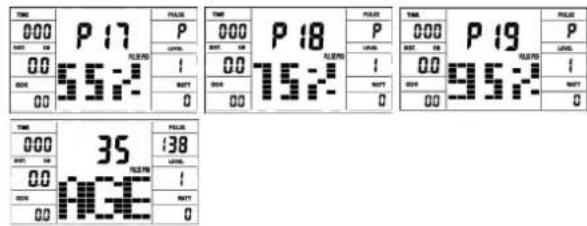
P17 - P19: HRC programs
Here the computer automatically calculates your maximum heart rate after entering your age and, depending on the program, the corresponding training target heart rate will be adjusted to 55% / 75% or 95%. This target value is displayed. The pedaling resistance is automatically adjusted by the computer in order to stay at this target frequency. Setting of the training parameters time / distance / calories / age by pressing the [F] key.
text_image
TIME 000 BET 48 00 000 00 P 17 55-2- P 000 BET 48 00 I BET 48 00 P 18 55-2- P 000 BET 48 00 I BET 48 00 P 19 55-2- P 000 BET 48 00 I BET 48 00 TIME 000 BET 48 00 00 35 55-2- P 000 BET 48 00 I BET 48 00 P 17 55-2- P 000 BET 48 00 I BET 48 00 P 18 55-2- P 000 BET 48 00 I BET 48 00 P 19 55-2- P 000 BET 48 02P20: Target training heart rate THF
Here you can specify your optimal training pulse rate THF. The pedal resistance is within a certain tolerance range automatically readjusted by the computer so that you are always in the specified pulse zone. Setting of the training parameters time / distance / calories / upper pulse limit by pressing the [F] key.
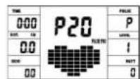
P21: Body-Fat program
Here you can get a body fat analysis and get exercise suggestion. Press the [F] key and select a user no. 1-8. Use the [F] key to access the different data [HIGHT] height = 120-250 cm, [male / [female, [YEAR] age = 10-99 years, [WEIGHT] bodyweight = 20 -200kg) one after the other and set them to your data using the [+/-] keys. Then press the [Start/Stop] key and grab the hand pulse sensors to measure your body fat.
After about 10 seconds, the display show body your fat in%, BMI and BMR as well as a suggested exercise program. Press [Start/Stop] key to exit body fat test and press again to start exercising this program.
| Gender → Bodytype ↓ | Male ≤ 30 | Male > 30 | Female ≤ 30 | Female > 30 |
| Underweight < | 14% < 17% | < 17% < 20% | ||
| Healthy 14~20% | 17~23% 1 | 7~24% 20~27% | ||
| Slightly Overweight | 20.1~25% | 23.1~28% | 24.1~30% | 27.1~33% |
| Overweight 25.1 | ~35% 28.1 | ~38% 30.1~ | 40% 33.1~ | 43% |
| Obese > 35% > | 38% > 40% | > 43% |
Note:
- During body fat test, it will display Err2 if hand pulse sensors get no input.
- According to test result, 10 seconds have no operation or operation arbitrarily key, will get into system recommendation to toughen program.
ERROR MESSAGES:
Each time the computer is restarted, it will run a quick test for functionality. If something is not in order, it indicates possible errors:
E1 This symbol and a warning tone appear if the wiring is incorrectly connected or there is a fault in the resistance setting. Check all cable connections, especially at the connectors. After eliminating the error, press and hold the [Start/Stop] key for 3 seconds to reset the system.
PULSE RATE
1. Hand pulse measurement
On the left and right handlebar grip part two metal contact plates are insert as pulse sensors. Please take care that both hands at the same time in normal force on the sensors. During the heartbeat measurement a heart symbol flashes next to the pulse display. (The hand pulse measurement serves only for orientation, as it is caused by movement, friction, sweat etc. it can come to deviations from the actual pulse. A few people may cause malfunctions of hand pulse measurement. Should you have trouble with the hand pulse measurement, we recommend the use of a bluetooth chest belt.)
Attention! Heart rate monitor systems may be inaccurate. Excessive exercising can lead to serious damage or maybe to death. If dizziness or weakness is felt, stop exercising immediately.
2. Pulse belt pulse measurement
Optionally, you can use a compatible Bluetooth heart rate monitor to measure your heart rate (Christopeit-Sport heart rate monitor 2209). The measured pulse value is displayed in the heart rate display. Response time is up to 60 seconds. If both heart rate measurement methods are used at the same time, the hand heart rate measurement has priority.
Attention! The heart rate measurement is not for medical purposes suitable.
FITNESS NOTE / RECOVERY PULSE FUNCTION

Your ergometer offers the option of evaluating your individual fitness in the form of a „fitness grade“. The measuring principle is based on the fact that in healthy, well-trained people, the pulse rate drops faster within a certain period of time after training than in healthy, less well-trained people. To determine the fitness level, the difference between the pulse rate at the end of the training (start pulse) and the pulse rate one minute after the end of the training (end pulse) is used. Do not start this function until you have trained for some time. Before starting the recovery pulse function, you must have your current pulse rate displayed by placing your hands on the hand pulse sensors.
- Press the [Test] key and then place both hands on the sensors to measure your heart rate.
- The computer goes into STOP mode, a large heart symbol is shown in the middle of the display and the automatic recovery pulse measurement is initiated.
- The time in the display starts counting down at 0:60
- The start pulse at the beginning of the measurement is shown in the display. It is the average of the four highest heart rate values in the last 20 sec. before pressing the [Test] key.
- The currently measured pulse value is displayed in the [PULSE] display.
- After one minute has elapsed, the time is reduced to 0:00 and an acoustic signal sounds. The end pulse at the time 0:00 is displayed in the [PULSE] display. You can now take your hands off the heart rate sensors. After a few seconds, your fitness grade from F 1.0 - F 6.0 (school grade system) appears in the middle of the display.
KINOMAP APP
Sport, coaching, gaming and eSport are the keywords of the Kinomap app. This contains many kilometers of real film material to exercise inside as if you were outside; Tracking routes and analysis of your performance; Coaching content; Multiplayer mode; new posts daily; Official indoor races and more ...
Download the app and connect
Scan the adjacent QR code with your smartphone / tablet or use the search function at the Playstore (Android) or APP Store (IOS) to download the Kinomap APP. Register and follow the instructions in the APP. Activate Bluetooth on the smartphone or tablet and select the device manager in the app and then the appropriate product category there. Then select your type designation using the manufacturer logo "Christopeit Sport" to connect the sports equipment. Depending on the sports equipment, different functions are recorded by the APP via Bluetooth or data is exchanged.
Attention! The Kinomap app offers a free trial version for 14 days. You can then decide whether you want to continue training for free with the basic version or use the full range of the Kinomap app for a fee.
Current information and fees can be found at:
www.kinomap.com


IOS / ANDROID APP
CLEANING, CHECKS AND STORAGE
1. Cleaning
Use only a less wet cloth for cleaning. Attention! Never use benzene, thinner or other aggressive cleaning agents for surface cleaning as this damage caused. The device is only for private home use and for use suitable indoors. Keep the unit clean and moisture from the device.
2. Storage
Plug out the power supply unit while intending the unit for more than 4 weeks not to use. Push the saddle slide toward the handlebar and the seat support tube as deeply as possible into the frame. Choose a dry storage in-house and put some spray oil to the pedal bearings left and right, to the thread of the handlebar bolt, and on the thread of the quick release for saddle support. Cover the bike to protect it from being discolor by any sunlight and dirty through dust.
3. Checks
We recommend every 50 hours to review the screw connections for tightness, which were prepared in the assembly. Every 100 operating hours, you should put some spray oil at the pedal bearings left and right, to the thread of the handlebar bolt and to the thread of quick release for saddle support.
TROUBLESHOOTING
If you cannot solve the problem with the following information, please contact the authorized service center.
| Problem Possible Cause Solution | ||
| Computer has no value at Display if you press any key. | No power adapter is well plugged or wall power is without power. | Check that the power adapter is properly plugged in, possibly with another electric device check if the wall power is fine. |
| Computer is not counting data and do not switch on after start cycling. | Sensor impulse missing base on not well plugged connection | Check the plug connections at computer and inside of handlebar support. |
| Computer is not counting data and do not switch on after start cycling. | Sensor impulse missing base on not correct position of sensor. | Take off the cover and check the distance between magnet and Sensor. The magnet at turning belt wheel should have only less than < 5mm distance against the sensor position. |
| No pulse value Pulse cable is not plugged in. Check the separately pulse cable is well connected with computer. | ||
| No pulse value Pulse sensors not well connected. Screw out the screw for pulse | measurement and check if plugs are well connected and no damage at pulse cable. | |
GENERAL TRAINING INSTRUCTIONS
You must consider the following factors in determining the amount of training effort required in order to attain tangible physical and health benefits.
INTENSITY
The level of physical exertion during training must exceed the point of normal exertion, without going beyond the point of breathlessness and/or exhaustion. A suitable reference value can be the pulse. With each training session, the condition increases and therefore the training requirements should be adjusted. This is possible by extending the duration of the training, increasing the level of difficulty or changing the type of training.
TRAINING HEART RATE
To determine the training heart rate, you can proceed as follows. Please note that these are guide values. If you have health problems or are unsure, consult a doctor or fitness trainer.
01 Maximum heart rate calculation
The maximum pulse value can be determined in many different ways, since the maximum pulse depends on many factors. You can use the main-formula for the calculation (maximum heart rate = 220 - age). This formula is very general. It is used in many home sport products to determine the maximum heart rate. We recommend the Sally-Edwards-formula. This formula calculates the maximum heart rate more precisely and takes gender, age and body weight into account.
Sally-Edwards-formula:
Men:
Maximum heart rate = 214 - (0.5 x age) - (0.11 x body weight)
Women:
Maximum heart rate = 210 - (0.5 x age) - (0.11 x body weight)
02 Training heart rate calculation
The optimal training heart rate is determined by the goal of the training. Training zones were defined for this.
Health - Zone: Regeneration and Compensation
Suitable for: Beginners
Type of training: very light cardio training
Goal: recovery and health promotion. Building the basic condition.
Training heart rate = 50 to 60% of the maximum heart rate
Fat-Metabolism - Zone: Basics endurance training 1
Suitable for: beginners and advanced users
Type of training: light cardio training
Goal: activation of fat metabolism (calorie burning). improvement in endurance performance.
Training heart rate = 60 to 70% of the maximum heart rate
Aerobic - Zone: Basics endurance training 1 to 2
Suitable for: beginners and advanced
Type of training: moderate cardio training.
Goal: Activation of the fat metabolism (calorie burning), improving aerobic performance, Increase in endurance performance.
Training heart rate = 70 to 80% of the maximum heart rate
Anaerobic - Zone: Basics endurance training 2
Suitable for: advanced and competitive athletes
Type of training: moderate endurance training or interval training
Goal: improvement of lactate tolerance, maximum increase in performance.
Training heart rate = 80 to 90% of the maximum heart rate
Competition - Zone: Performance / Competition Training
Suitable for: athletes and high-performance athletes
Type of training: intensive interval training and competition training /
Goal: improvement of maximum speed and power.
Attention! Training in this area can lead to overloading of the cardiovascular system and damage to health.
Training heart rate = 90 to 100% of the maximum heart rate
Sample calculation
Male, 30 years old and weighs 80 kg. I am a beginner and would like to lose some weight and increase my endurance.
01: Maximum pulse - calculation
Maximum heart rate = 214 - (0.5 x age) - (0.11 x body weight)
Maximum heart rate = 214 - (0.5 x 30) - (0.11 x 80)
Maximum pulse = approx. 190 beats/min
02: Training heart rate calculation
Due to my goals and training level, the fat metabolism zone suits me best.
Training heart rate = 60 to 70% of the maximum heart rate
Training heart rate = 190 x 0.6 [60%]
Training heart rate = approx. 114 beats/min
After you have set your training heart rate for your training condition or Once you have identified goals, you can start training. Most of our endurance training equipment have heart rate sensors or are heart rate belt compatible. So you can check your heart rate on the monitor during the workouts. If the pulse rate is not shown on the computer display or you want to be on the safe side and want to check your pulse rate, which could be incorrectly displayed due to possible application errors or similar, you can use the following tools:
a. Pulse measurement in the conventional way (sensing the pulse beat, e.g. on the wrist and counting the beats within a minute).
b. Heart rate measurement with suitable and calibrated heart rate measuring devices (available from medical supply stores).
c. Heart rate measurement with other products such as heart rate monitors, smartphones....
FREQUENCY
Most experts recommend the combination of a health-conscious diet, which must be adjusted according to the training goal, and physical exercise three to five times a week. A normal adult needs twice a week exercise to maintain its current condition. To improve his condition and change his body weight, he needs at least three training sessions per week. Ideal of course is a frequency of five training sessions per week.
TRAINING PLAN
Each training session should consist of three training phases: "warmup phase", "training phase" and "cool-down phase". In the "warm-up phase" the body temperature and the oxygen supply should be increased slowly. This is possible through gymnastic exercises over a period of five to ten minutes. After that you start with actual training "training phase". The training load should be adapted according to the training heart rate. In order to support the circulation after the training phase and to preventaching or strained muscles later, it is necessary to follow the training phase with a cool-down phase. This should be consist of stretching exercises and/or light gymnastic exercises for a period of five to ten minutes.
Example - stretching exercises for the warm-up and cool-down phases
Start your warm up by walking on the spot for at least 3 minutes and then perform the following gymnastic exercises to the body for the training phase to prepare accordingly. The exercises do not overdo it and only as far run until a slight drag felt. This position will hold a while.

natural_image
Sequence of four sequential illustrations showing a person performing a stretching or kneeling movement (no text or symbols)Reach with your left hand behind your head to the right shoulder and pull with the right hand slightly to the left elbow. After 20sec. switch the arm.
Bend forward as far forward as possible and let your legs almost stretched. Show it with your fingers in the direction of toe. 2 x 20sec.
Sit down with one leg stretched out on the floor and bend forward and try to reach the foot with your hands. 2 x 20sec.
Kneel in a wide lunge forward and support yourself with your hands on the floor. Press the pelvis down. Change the leg after 20 sec.
MOTIVATION
The key to a successful program is regular training. You should set a fixed time and place for each day of training and prepare yourself mentally for the training. Only train when you are in the mood for it and always have your goalin view. With continuous training you will be able to see how you are progressing day by day and are approaching your personal training goal bit by bit.
PARTS LIST – SPARE PARTS LIST
| Type: | AL2 S Silber / Black |
| Order-Nr.: | 2495-2497 |
| Date of technical data: | 13.05.2024 |
| Dimensions approx: [cm]: | L 96 x W 59 x H 134 |
| Space requirements [ m^2 ]: | 2,5 |
| Weight approx. [kg]: | 27 |
| Load max. (User weight) [kg]: | 150 |
FEATURES
- Magnetic brake system with approx. 9 KG flywheel
- Motor- and Computer-controlled resistance, with 24 manually adjustable load steps
• 10 installed programs
• 4 heart rate programs
• 5 individual programs
• 1 manually program - 1 speed independent program, power control in steps of 5 Watt (10 – 300 Watt)
• 1 Body Fat program - Pulse measurement by hand pulse sensors or bluetooth heart rate belt
- Bluetooth connection for Kinomap APP / Zswift
- Handlebar and saddle incline adjustable
- Saddle horizontally- and vertically-adjustable
-
Wheels for easier transportation
• Power plug (Adapter) -
Backlight Display, with 6 windows showing functions: Speed, time, distance, approx. calories, Pedal revolutions per minute, ODO, Watt and heart rate.
- Input of limits for time, distance and approx. calories, watt and heart rate, Announcement of higher limits
• Fitness test (Recovery)
NOTE
Please contact us if any components are defective or missing, or if you need any spare parts or replacements in future.
This product is created only for private Home sports activity and not allowed to us in a commercial or professional area. Home Sport use class H/A.
| Illustration No. | Designation | Dimension mm | Quantity | Attached to | ET Number AL2 Silber (2497) | ET Number AL2 Black (2495) |
| 1 Main Frame | 1 33-9212-01-SI 33-1107101-SW | |||||
| 2 Screw M4x | 12 4 17 39-10188 39-10188 | |||||
| 3 Connection | cable 1 16+17 36-1107207-BT | BT 36-1107207-BT | ||||
| 4 | Pulse unit with wire | 2 | 7 | 36-9211-08-BT | 36-9211-08-BT | |
| 5 Square end cap | 2 33 36-9211-23-BT | 36-9211-23-BT | ||||
| 6 | Fixed bracket | 1 | 29+33 | 33-9211-08-SI | 33-9211-08-SI | |
| 7 Handlebar | 1 12 33-9211-02-SI | 33-1106102-SW | ||||
| 8 Washer | 2 25+56 39-10520 39-10520 | |||||
| 9 Bushing | 1 25 36-9613209-BT | 36-9613209-BT | ||||
| 10 | Handle cover | 1 | 7 | 36-9211-09-BT | 36-9211-09-BT | |
| 11 | Handlebar support cover | 1 | 12 | 36-1107-04-BT | 36-11072-04-BT | |
| 12 | Handlebar post | 1 | 1 | 33-9212-02-SI | 33-1107102-SW | |
| 13 | Curved washer | 8//19 | 8 | 14+28 | 39-9966-CR | 39-9966-CR |
| 14 | Screw M8x16 4 12 39-9886-CR | 39-9886-CR | ||||
| 15 | Spring washer | for M8 | 8 | 14+28 | 39-9864-VC | 39-9864-VC |
| 16 | Motor cable | 1 | 3 | 36-1107208-BT | 36-1107208-BT | |
| 17 | Computer | 1 | 12 | 36-2495-03-BT | 36-2495-03-BT | |
| 18 L | End cap left | 1 | 20 | 36-9211-13-BT | 36-9211-13-BT | |
| 18 R | End cap right | 1 | 20 | 36-1107-08-BT | 36-1107-08-BT | |
| 19 | Cap nut | 4 28 39-9900-CR | 39-9900-CR | |||
| 20 | Front stabilizer | 1 | 1 | 33-9211-04-SI | 33-1106104-SW | |
| 21 L | Crank left | 9/16" | 1 | 41 | 33-1107-12-SI | 33-1107-12-SI |
| 21 R | Crank right | 9/16" | 1 | 41 | 33-1107-13-SI | 33-1107-13-SI |
| 22 L | Pedal left | 9/16" | 1 | 21L | 36-1107-14-BT | 36-1107-14-BT |
| 22 R | Pedal right | 9/16" | 1 | 21R | 36-1107-15-BT | 36-1107-15-BT |
| 23 | Small plastic cover | 2 | 21 | 36-9840-15-BT | 36-9840-15-BT | |
| 24 | Bolt | M8x25 2 21 39-10455 39-10455 | ||||
| 25 | Hand grip bolt | 1 | 12 | 36-9211-16-BT | 36-9211-16-BT | |
| 26 | End cap with height adjustment | 2 | 27 | 36-9211-17-BT | 36-9211-17-BT | |
| 27 | Rear stabilizer | 1 | 1 | 33-9211-05-SI | 33-1106105-SW | |
| 28 | Bolt | M8x75 | 4 | 20+27 | 39-10019-CR | 39-10019-CR |
| 29 | Saddle post | 1 | 1+33 | 33-9211-06-SI | 33-1106106-SW | |
| 30 | Knob bolt | 1 | 1+29 | 36-9211-18-BT | 36-9211-18-BT | |
| 31 | Knob | 1 | 6+33 | 36-9211-19-BT | 36-9211-19-BT | |
| 32 | Washer | 10//20 | 1 | 31 | 39-9989-CR | 39-9989-CR |
| 33 | Saddle slide | 1 | 29 | 33-9211-07-SI | 33-1106107-SW | |
| 34 Saddle 1 | 33 36-9211-20-BT 36-9211-20-BT | |||||
| 35 End cap 2 | 7 36-9211-21-BT 36-9211-21-BT | |||||
| 36 Foam grip | 2 7 36-9211-22-BT 36-9211-22-BT | |||||
| 37 Top cover | 1 79 36-1107-06-BT 36-1107205-BT | |||||
| 38 C-clip | C 17 | 2 41 36-9211-33-BT 36-9211-33-BT | ||||
| 39 | Bearing | 6203ZZ | 2 | 1+41 | 39-9947 | 39-9947 |
| 40 | Wave washer | 17//22 | 1 | 41 | 36-9918-22-BT | 36-9918-22-BT |
| 41 | Axle | 1 | 39+42 | 33-9211-09-SI | 33-9211-09-SI | |
| 42 Belt wheel | 1 41 36-9211-24-BT 36-9211-24-BT | |||||
| 43 | Belt | 430 PJ6 | 1 | 42+68 | 36-9211-25-BT | 36-9211-25-BT |
| 44 Bolt | 2 47 39-10120-SW 39-10120-SW | |||||
| 45 | Spring washer | for M6 | 2 | 44 | 39-9865-SW | 39-9865-SW |
| 46 C-clip | C12 2 44 | 36-9111-39-BT 36-9111-39-BT | ||||
| 47 Magnetic bracket axle | 1 48 36-9211-26-BT 36-9211-26-BT | |||||
| 48 | Magnetic bracket | 1 | 47+49 | 33-9211-12-SI | 33-9211-12-SI | |
| 49 Spring | 1 1+48 | 36-9211-27-BT 36-9211-27-BT | ||||
| 50 | Bolt | M6x35 | 1 | 1+48 | 39-10306 | 39-10306 |
| 51 Nut | M6 | 1 50 39-9861-VZ 39-9861-VZ | ||||
| 52 | Spring washer | for M10 | 2 | 57 | 39-9995 | 39-9995 |
| 54 Idler wheel | 1 57 36-9211-28-BT 36-9211-28-BT | |||||
| 55 Bushing | 1 56 36-9211-14-BT 36-9211-14-BT | |||||
| 56 | Screw | M8x20 | 1 | 57 | 39-10095-CR | 39-10095-CR |
| 57 Idler wheel bracket | 1 1 33-9211-11-SI 33-9211-11-SI | |||||
| 58 Spring | 1 1+57 | 36-9211-37-BT 36-9211-37-BT | ||||
| 59 Nylon nut | M10 | 1 57 39-9981 39-9981 | ||||
| 60 Axle nut | M10x1.0 2 69 39-9820-SW 39-9820-SW | |||||
| 61 | Screw | M6x40 | 2 | 1+69 | 39-10000 | 39-10000 |
| 62 U-piece | 2 61 36-9713-55-BT 36-9713-55-BT | |||||
| 63 Nut | M6 | 2 61 39-9861-VZ 39-9861-VZ | ||||
| 64 Axle nut slim | M10x1.0 2 69 39-9820 39-9820 | |||||
| 65 Spacer ring | 1 69 36-9211-15-BT 36-9211-15-BT | |||||
| 66 | Tension cable | 1 | 48+74 | 36-9211-41-BT | 36-9211-41-BT | |
| 67 | Bearing | 6000Z | 2 | 68+69 | 39-9998 | 39-9998 |
| 68 Flywheel | 1 67 33-1107-01-SI 33-1107-01-SI | |||||
| 69 Flywheel axle | 1 67 33-9211-13-SI 33-9211-13-SI | |||||
| 70 | Screw | 3,5x20 | 17 | 74+79 | 39-9909-SW | 39-9909-SW |
| 71 | Screw | 3x10 | 12 | 20+27+72 | 39-10127-SW | 39-10127-SW |
| 72 Round cover | 2 79 36-1107-05-BT 36-1107206-BT | |||||
| 73 AC adaptor | 9V=DC/1A | 1 83 36-1420-17-BT 36-1420-17-BT | ||||
| 74 Serve motor | 1 16 36-1721-09-BT 36-1721-09-BT | |||||
| 75 Rubber ring | 1 1 36-9211-31-BT 36-9211-31-BT | |||||
| 76 | Nylon nut | M8 | 4 | 56+78 | 39-9918-CR | 39-9918-CR |
| 78 | Bolt | M8x16 | 3 | 41+42 | 39-9823-SW | 39-9823-SW |
| 79 L | Chain cover left | 1 | 1+79R | 36-1107-11-BT | 36-1107211-BT | |
| 79 R | Chain cover right | 1 | 1+79L | 36-1107-12-BT | 36-1107212-BT | |
| 80 Screw | 3x10 | 2 81 39-10127 39-10127 | ||||
| 81 Sensor | 1 1 36-9212-07-BT 36-9212-07-BT | |||||
| 82 Washer | 2 44 39-10013-VC 39-10013-VC | |||||
| 83 DC connection cable | 1 79L 36-1721-07-BT 36-1721-07-BT | |||||
| 84 | Washer | 4//10 | 4 | 2 | 39-10510 | 39-10510 |
| 85 Saddle bushing | 1 1 36-9211-40-BT 36-9211-40-BT | |||||
| 86 | Wave washer | 17//23 | 1 | 41 | 36-9918-22-BT | 36-9918-22-BT |
| 87 Small pulley | 1 69 36-9211-38-BT 36-9211-38-BT | |||||
| 88 | Tool set | 1 | 36-9211-34-BT | 36-9211-34-BT | ||
| 89L | Pedal strap left | 1 | 22L | 36-9504-48-BT | 36-9504-48-BT | |
| 89R | Pedal strap right | 1 | 22R | 36-9504-46-BT | 36-9504-46-BT | |
| 90 Assembly and exercise instruction | 1 | 36-2495-04-BT 36-2495-04-BT | ||||

text_image
0 5 10 15 20 25 30 40 50 60 70 80 90 100SOMMAIRE
Page Contenu
text_image
Technical diagram of a mechanical device with numbered components for identification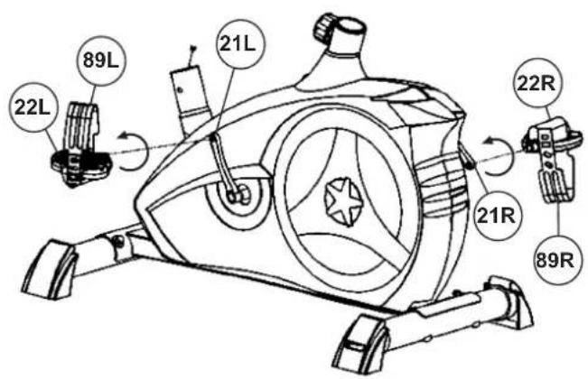
text_image
89L 22L 21L 22R 21R 89RÉTAPE N° 4
text_image
Technical diagram of a stationary exercise machine with numbered components for identification.ÉTAPE N° 5
text_image
Technical diagram of a stationary exercise machine with numbered components and an inset close-up view highlighting key parts.ÉTAPE N° 6
text_image
Technical diagram of a stationary exercise bike with numbered components and labeled partsÉTAPE N° 7
natural_image
Line drawing of a stationary exercise machine with rotating legs and arm (no text or symbols)
Monter
natural_image
Technical line drawing of a stationary exercise machine inside a transparent enclosure, showing front and side views (no text or symbols)natural_image
Line drawing of a stationary exercise machine inside a transparent cube, with dimension annotations (1560, 1790) and page number 2200 (no text or symbols on the device itself)text_image
TIME 000 P 1 00 00 00 P P 6 00 00 P2 P 00 00 18 00 00 P3 P 00 00 3 00 00 TIME 000 P 4 00 00 00 P5 P 00 00 3 00 00 P6 P 00 00 6 00 00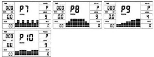
text_image
TIME 000 P7 PULSE TIME P8 PULSE TIME P9 PULSE RDT. 000 000 000 000 000 LEVEL 9 LEVEL 9 00 LEVEL 9 00 00 00 00 4 LEVEL 9 00 00 00 LEVEL 9 00 4 LEVEL 9 00 00 4 LEVEL 9 00 4 LEVEL 9 00 4 LEVEL 9 00 4 LEVEL 9 00 4 LEVEL 9 00 4 LEVEL 9 00 4 LEVEL 9 00 4 LEVEL 9 00 4 LEVEL 9 00 4 LEVEL 9 00 4 LEVEL 9 00 4 LEVEL 9 P10 P10 P10 P10 RDT. 000 000 000 000 LEVEL 9 LEVEL 9 00 00 0 LEVEL 9 LEVEL 9 00 00 0 LEVEL 9 LEVEL 9 00 00 0 LEVEL 9 LEVEL 9 00 00 0 LEVEL 9 LEVEL 9 00 00 0 LEVEL 9 LEVEL 9 00 00 0 LEVEL 9 LEVEL 9 00 00 0 LEVEL 9 LEVEL 9 56.56.56.56.56.56.56.56.56.56.56.56.56.56.56.56.56.56.56.56.56.56.56.56.56.56.56.56.56.56.56.56.56.56. LEVEL 9 LEVEL 9 56.56.56.56.56.56.56.56.56.56.56.56.56.56.56.56.56.56.56.56.56.56.56.56.56.56.56.56.56.56. LEVEL 9 LEVEL 9 57.77.77.77.77.77.77.77.77.77.77.77.77.77.77.77.77.77.77.77.77.77.77.77.77.77. LEVEL 9 LEVEL 9 58.33.33.33.33.33.33.33.33.33.33.33.33.33.33.33.33.33.33.33.33. LEVEL 9 LEVEL 9 58.22.22.22.22.22.22.22.22.22.22.22.22. LEVEL 9 LEVEL 9 58.11.11.11.11.11.11.11.11.11. LEVEL 9 LEVEL 9 P18 P18 P18 P18 P18 P18 P18 P18 P18 P18 P18 P18 P18 P18 P18 P18 P18 P18 P18 P18 P18 P18 P18 P18 P18 P18 P18 P18 P18 P18 P18 P18 P18 P18 P
P11 - P15: indiv. programmes (U1-U5)
text_image
TIME 000 BAT 00 00 000 00 P 11 U 1 P 000 BAT 00 00 I 00 WAT 00 P 12 U 2 P 000 BAT 00 00 I 00 WAT 00 P 13 U 3 P 000 BAT 00 00 I 00 WAT 00 TIME 000 BAT 00 00 000 BAT 00 00 I 00 WAT 00 P 14 U 4 P 000 BAT 00 00 I 00 WAT 00 P 15 U 5 P 000 BAT 00 00 I 00 WAT 00P16: Watts-Programme
text_image
Technical diagram of a mechanical device with numbered components for identification
text_image
89L 22L 21L 22R 21R 89RSTAP 4
text_image
Technical diagram of a stationary exercise machine with numbered components for identification.STAP 5
text_image
Technical diagram of a stationary exercise machine with numbered components and an inset close-up view highlighting key parts.STAP 6
text_image
Technical diagram of a stationary exercise bike with numbered components and labeled partsSTAP 7
natural_image
Line drawing of a stationary exercise machine with rotating arms and handle (no text or symbols)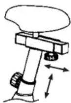
Opstappen
natural_image
Technical line drawing of a stationary exercise machine inside a transparent enclosure, showing front and side views (no text or symbols)Oefenterrein in mm
(Voor de apparaat-en gebruikers)
natural_image
Line drawing of an exercise machine inside a transparent cube, showing front and side views with no text or symbols.Oefenterrein in mm
(Voor de apparaat-en gebruikers omringend 600mm)
text_image
CHRISTOPERT® P1 TIME 0:00 P1 0:00 0:00 0:9 P2 P3 LEVEL1 6 WATT 0 F Start/Stop TestFUNCTIE
text_image
TIME 000 P 17 00 00 P 18 000 P 19 000 P 15 000 00 00 35 000 P 138 00 00 00 P 128 00 00 P 118 00 00 P 95 00 00 P 85 00 P 75 00 P 65 00 P 55 00 P 45 00 P 35 00 P 25 00 P 15 00 P 12 00 P 10 00 P 8 00 P 6 00 P 5 00 P 4 00 P 3 00 P 2 00 P 1 35 MGEP20: Beoogde trainingshartslagfrequentie THF
bar
| TIME | SPEED | PUEL | TIME | SPEED | PUEL | TIME | SPEED | PUEL | |---|---|---|---|---|---|---|---|---| | 4000 | 00 | 00 | 2000 | 00 | 00 | 4000 | 00 | 00 | | LEVEL | 00 | 6 | 6 | 6 | 6 | LEVEL | 6 | 6 | | 000 | 00 | 0 | 0 | 0 | 0 | 0 | 0 | 0 | | 000 | 00 | 0 | 0 | 0 | 0 | 0 | 0 | 0 | | 4000 | 00 | PUEL | TIME | SPEED | PUEL | PUEL | PUEL | PUEL | | LEVEL | 00 | PUEL | PUEL | PUEL | PUEL | PUEL | PUEL | PUEL | | 000 | 00 | 6 | 6 | 6 | 6 | 6 | 6 | 6 | | 000 | 00 | 0 | 0 | 0 | 0 | 0 | 0 | 0 | The visual displays are schematic diagrams of the speed and pole measurements. The labels 'P' and 'R' appear to denote the values at the top of the charts.FOUTMELDINGEN:
Competitie - Zone: Prestaties / Competitie Training
02: Training hartslagberekening
natural_image
Sequence of four sequential illustrations showing a person performing a stretching or kneeling movement (no text or symbols)text_image
Technical diagram of a mechanical device with numbered components for identification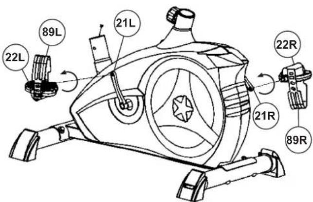
text_image
22L 89L 21L 22R 21R 89RKROK 4
text_image
Technical diagram of an exercise machine with numbered components for identification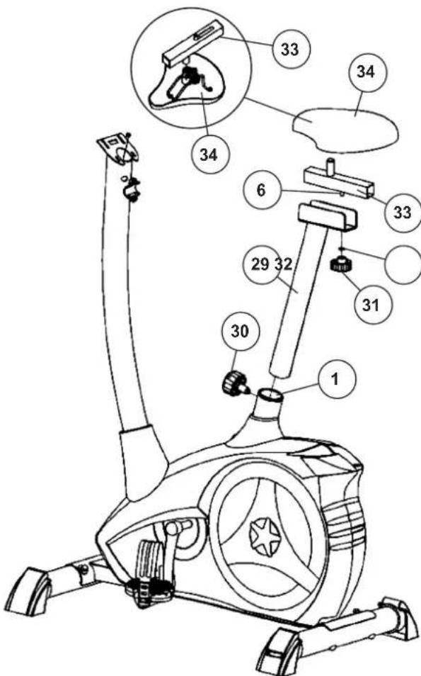
text_image
Technical diagram of a stationary exercise machine with numbered components and an inset close-up view highlighting key parts.KROK 6
text_image
Technical diagram of a stationary exercise bike with numbered components and labeled partsKROK 7
natural_image
Line drawing of a stationary exercise machine with rotating arms and legs (no text or symbols)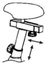
Nastupování
natural_image
Line drawing of a stationary exercise machine inside a transparent enclosure, labeled with dimensions 960 and 590 (no text or symbols on the device itself)natural_image
Line drawing of a stationary exercise machine inside a transparent cube, with dimension labels (1560, 1790) and page number (2200) visible.1. MANUAL: Manual program
| TIME 000 DATE: 00 | P 17 55-2- | PULSE 00 | TIME 000 DATE: 00 | P 18 55-2- | PULSE 00 | TIME 000 DATE: 00 | P 19 55-2- | PULSE 00 |
| 00 DATE: 00 | I NATT 0 | 00 NATT 0 | I NATT 0 | I NATT 0 | 00 NATT 0 | I NATT 0 | I NATT 0 |
bar
| Time | Speed | Pulse | Speed | Pulse | |---|---|---|---|---| | 4000 | 0.0 | P | 2000 | P | | 10V | 0.0 | 10V | 10V | 4000 | | 6000 | 0.0 | 6 | 6 | 600 | | 12000 | 0.0 | 5 | 5 | 5 | | 18000 | 0.0 | 3 | 3 | 3 | | 24000 | 0.0 | 2 | 2 | 2 | | 30000 | 0.0 | 1 | 1 | 1 | | 36000 | 0.0 | 0.5 | 0.5 | 0.5 | The visual displays the 'SPEED' and 'Voltage Level' data points for each configuration. The 'TIME' values are explicitly labeled on the charts.CHYBOVÉ HLÁŠKY
natural_image
Sequence of four sequential illustrations showing a person performing a stretching or kneeling movement (no text or symbols)text_image
Technical diagram of a vehicle air conditioner with numbered components and labeled parts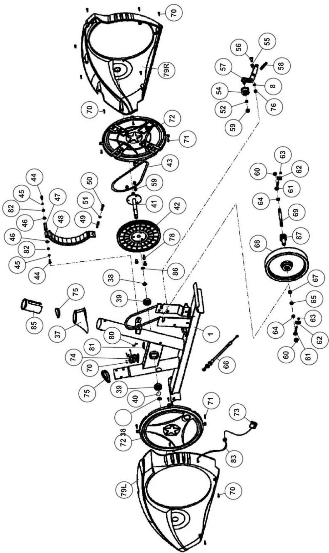
text_image
Exploded view diagram of a mechanical device with numbered components and labeled parts© by Top-Sports Gilles GmbH D-42551 Velbert (Germany)