Velo Fit - Exercise bike Christopeit - Free user manual and instructions
Find the device manual for free Velo Fit Christopeit in PDF.

| Product type | Folding exercise bike |
| Brand | Christopeit |
| Model | Velo Fit (Order no. 2560) |
| Dimensions (assembled) | L 95 x W 55 x H 132 cm |
| Dimensions (folded) | L 42 x W 55 x H 152 cm |
| Net weight | 22 kg |
| Maximum user weight | 120 kg |
| Power supply | 2 AAA 1.5V batteries (not included) |
| Resistance | 14 levels, magnetic braking system |
| Flywheel | Approx. 5 kg |
| Display | LCD computer: time, speed, distance, ODO, calories, pulse |
| Pulse measurement | Hand grip sensors on handlebars |
| Computer functions | SCAN, SPD, DIST, TIME, CAL, ODO, PULSE; pre-setting of values |
| Seat | Height adjustable with backrest |
| Handlebars | Adjustable, with additional grip |
| Folding | Yes, by locking pin |
| Transport | Rollers on front foot |
| Holder | Smartphone/tablet holder |
| Cleaning | Damp cloth; no aggressive detergents |
| Maintenance | Check screws every 50 h; lubricate threads every 100 h |
| Class | Domestic (H/C) according to EN ISO 20957 |
| Warranty / Spare parts | Original spare parts available; see list in manual |
| Country of origin | Not specified |
Frequently Asked Questions - Velo Fit Christopeit
User questions about Velo Fit Christopeit
0 question about this device. Answer the ones you know or ask your own.
Ask a new question about this device
Download the instructions for your Exercise bike in PDF format for free! Find your manual Velo Fit - Christopeit and take your electronic device back in hand. On this page are published all the documents necessary for the use of your device. Velo Fit by Christopeit.
USER MANUAL Velo Fit Christopeit
Assembly and operating instructions
Order No.: 2560 GB
Page: 13-22

natural_image
Black Cherylift bike with curved arm and seat, no visible text or symbols on the device itselfINHALTSÜBERSICHT
InhaltSeite


SCHRITT 4

SCHRITT 6
Montage der Pedalen (44+45) an den Pedalarmen (80+81).
natural_image
Line drawing of a stationary exercise bike with adjustable arms and legs (no text or symbols)[PULSE] Pulsanzeige:
natural_image
Diagram of two battery components with labeled parts, no text or symbols presentnatural_image
Four sequential illustrations showing a person performing a stretching or kneeling movement (no text or symbols)13 Important recommendations and safety instructions
14-16 Assembly instructions
17 Use of the device
18-19 Computer
19 Cleaning, checks and storage
19 Troubleshooting
20 General training instructions
21-22 Parts list – Spare parts list
54-55 Exploded drawing
We congratulate you on your purchase of this home training sports unit and hope that we will have a great deal of pleasure with it. Please take heed of the enclosed notes and instructions and follow them closely concerning assembly and use. Please do not hesitate to contact us at any time if you should have any questions.
IMPORTANT RECOMMENDATIONS AND SAFETY INSTRUCTIONS
Our products are all TÜV tested and therefore represent the highest current safety standards. However, this fact does not make it unnecessary to observe the following principles strictly.
-
Assembly the machine exactly as described in the installation instructions and use only the enclosed, specific parts of the machine. Before assembling, verify the completeness of the delivery against the delivery notice and the completeness of the carton against the assembly steps in the installation and operating instructions.
-
Before the first use and at regular intervals (approximately every 50 Operating hours) check the tightness of all screws, nuts and other connections and the access shafts and joints with some lubricant so that the safe operating condition of the equipment is ensured. In particular, the adjustment of saddle need smooth function and good condition.
-
Set up the machine in a dry, level place and protect it from moisture and water. Uneven parts of the floor must be compensated by suitable measures and by the provided adjustable parts of the machine if such are installed. Ensure that no contact occurs with moisture or water.
-
Place a suitable base (e.g. rubber mat, wooden board etc.) beneath the machine if the area of the machine must be specially protected against indentations, dirt etc.
-
Before beginning training, remove all objects within a radius of 2 metres from the machine.
-
Do not use aggressive cleaning agents to clean the machine and employ only the supplied tools or suitable tools of your own to assemble the machine and for any necessary repairs. Remove drops of sweat from the machine immediately after finishing training.
-
Attention! Systems of the heart frequency supervision can be inexact. Excessive training can lead to serious health damage or to the death. Consulta doctor before beginning a planned training programme. He can define the maximum exertion (pulse, Watts duration of training etc.) to which you may expose yourself and can give you precise information on the correct posture during training, the targets of your training and your diet. Never train after eating large meals. This item is not suitable for therapeutically purposes!
-
Only train on the machine when it is in correct working order. Use original spare parts only for any necessary repairs. Attention! Replace the worm parts immediately and keep this equipment out of use until repaired.
-
When setting the adjustable parts, observe the correct position and the marked, maximum setting positions and ensure that the newly adjusted position is correctly secured.
-
Unless otherwise described in the instructions, the machine must only be used for training by one person at a time. The exercise time should not overtake 45 min/daily.
-
Wear training clothes and shoes which are suitable for fitness training with the machine. Your clothes must be such that they cannot catch during training due to their shape (e.g. length). Your training shoes should be appropriate for the trainer, must support your feet firmly and must have non-slip soles.
-
Attention! If you notice a feeling of dizziness, sickness, chest pain or other abnormal symptoms, stop training and consult a doctor.
-
Never forget that sports machines are not toys. They must therefore only be used according to their purpose and by suitably informed and instructed persons.
-
People such as children, invalids and handicapped persons should only use the machine in the presence of another person who can give aid and advice. Take suitable measures to ensure that children never use the machine without supervision. Ensure that the person conducting training and other people never move or hold any parts of their body into the vicinity of moving parts.
-
It must be ensured that the user and other people never go or stand with any body parts in the area of still moving parts.
-
At the end of its life span this product is not allowed to dispose over the normal household waste, but it must be given to an assembly point for the recycling of electric and electronic components. You may find the symbol on the product, on the instructions or on the packing. The materials are reusable in accordance with their marking. With the re-use, the material utilization or the protection of our environment. Please ask the local administration for the responsible disposal place.
-
To protect the environment, do not dispose of the packaging materials, used batteries or parts of the machine as household waste. Put these in the appropriate collection bins or bring them to a suitable collection point.
-
This machine is a speed-dependant machine, i.e. the power increases with increasing speed, and the reverse.
-
The machine is equipped with 14-speed resistance adjustment. This makes it possible to reduce or increase the braking resistance and thereby the training exertion. Turning the adjusting knob for the resistance setting towards stage 1 reduces the braking resistance and thereby the training exertion. Turning the adjusting knob for the resistance setting towards stage 14 increases the braking resistance and thereby the training exertion.
-
This machine has been tested in compliance with wird EN ISO 20957-1:2025 and EN ISO 20957-5:2017 „H/C“. The maximum permissible load (=body weight) is specified as 120 kg. The classification of H/C means this exercise bike is designed for home use only and with good accuracy class. This item's computer corresponds to the basic demands of the directive of EMC 2014/30/EU.
-
The assembly and operating instructions is part of the product. If selling or passing to another person the documentation must be provided with the product.
ASSEMBLY INSTRUCTIONS
Remove all the separate parts from the packaging, lay them on the floor and check roughly that all are there on the base of the assembly steps. Please note that a number of parts have been connected directly to the main frame and preassembled. This will make it easier and quicker for you to assemble the equipment. Assembly time: 30 - 40 min.
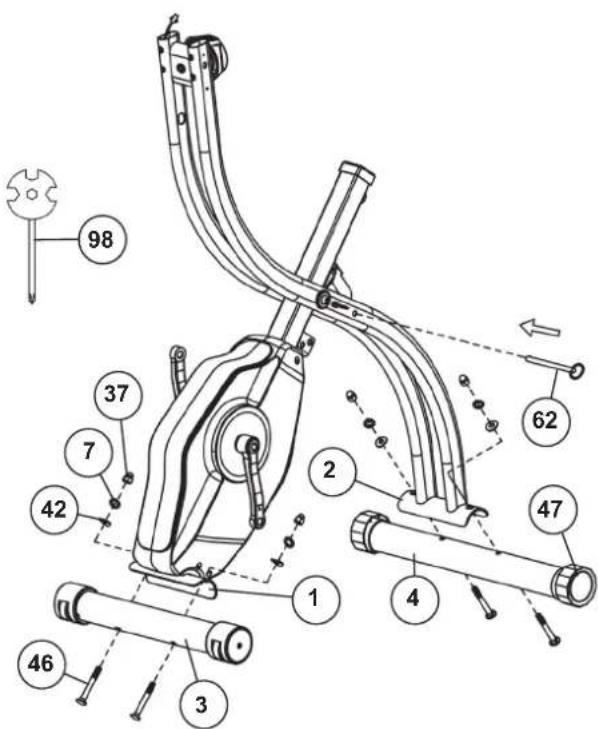
STEP 1
Install of front and rear foot (3+4) to the main and base frame(1+2).
- Pull out the safety pin (62) to fold the two frames (1+2) apart. Secure this position by inserting the safety pin (62).
- Insert the foot bars (3+4) in the holder of the frames (1+2) and adjust so that the hole patterns of the holders and the foot bars (3+4) are aligned. The rear foot (4) has preassembled eccentric caps (47).
- Push one screw (46) through each hole. Fit the screw ends of (46) with one and curved washer (42) an spring washer (7) each and fasten with a cap nut (37).
(Note! If the machine has positioned for training on an uneven floor, this can be compensated at any place by turning the eccentric caps (47)).
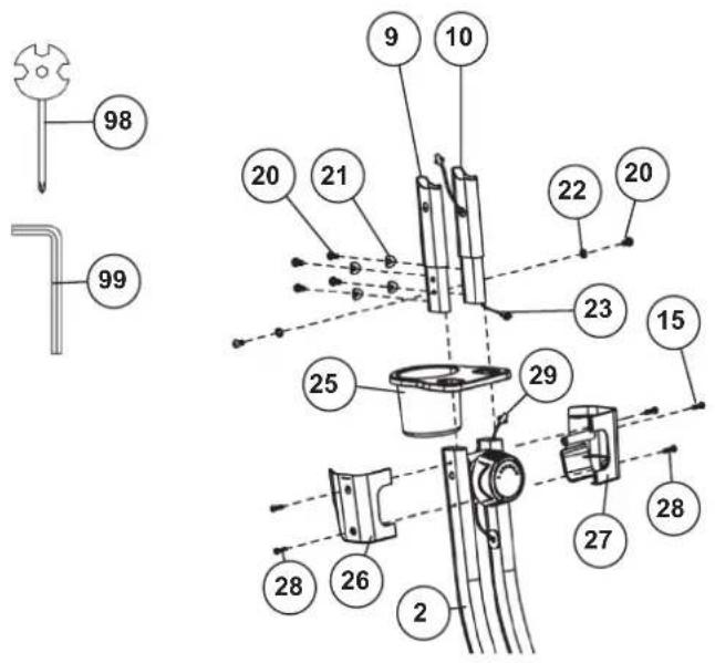
STEP 2
Instal of the handlebar mounts (9+10) and the shelf (25).
- Remove the screws 20 with the washers (21+22) from the left and right handlebar mounts (9+10).
- Insert the handlebar mounts (9+10) through the shelf (25) and guide them to the main frame (2). Connect the connecting cables 1+2 (23+29) together and insert the handlebar mounts (9+10) onto the main frame (2) so that no cables are pinched. Screw the handlebar mounts (9+10) to the main frame using the M6x12 screws (20), curved washers (21), and washers (22).
- Insert the left and right shelf covers (26+27) around the main frame (2) and secure them with the screws (28+15). Slide the shelf (25) flush onto the left and right shelf covers (26+27).
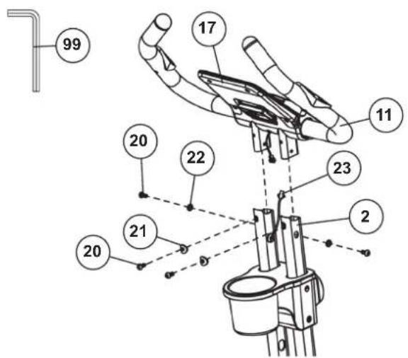
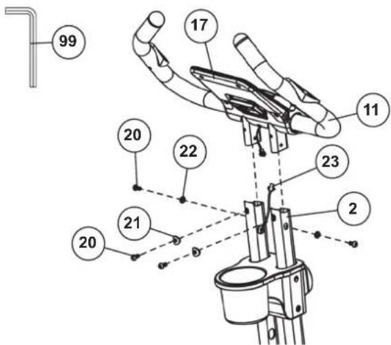
STEP 3
Install of the handlebar unit (11) with the computer (17) on the main frame (2).
- Remove the screws (20) with the washers (21+22) from the handlebar unit (11).
- Guide the handlebar unit (11) to the main frame (2) and connect the connecting cables 2 (23) to the computer (17). Place the handlebar unit (11) onto the main frame (2), ensuring that no cables are pinched, and screw the handlebar unit (11) to the main frame using the M6x12 screws (20), curved washers (21), and washers (22).
- Insert the batteries (type AAA-1.5V) into the battery compartment on the back of the computer, observing the correct polarity. (Batteries for the computer are not included. Please purchase them from a retailer.)


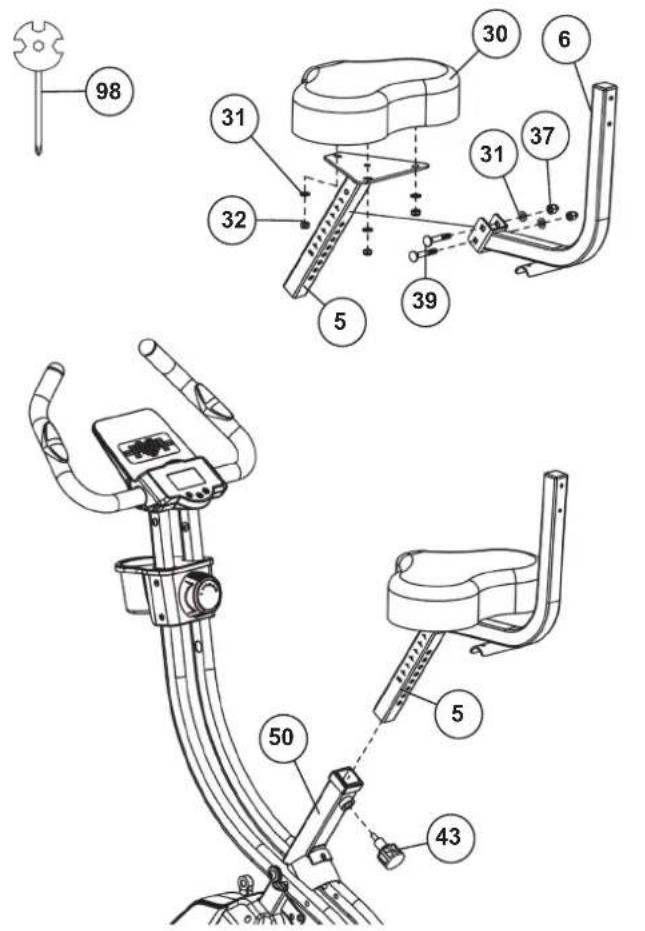
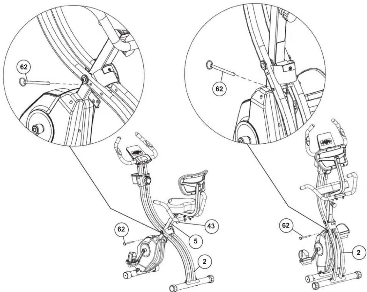
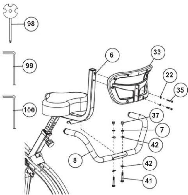
STEP 4
Installation of saddle (30) and back pad holder (6).
-
Guide the back pad holder (6) with the lower one to the attachment point at seat bracket (5) and insert the carriage bolts M8x45 (39) through the side of the back cushion holder (6) and seat holder (5). Place a washer 8//16 (31) on each screw end and tighten this connection with the cap nut M8 (37).
-
Place the seat (30) on the mounting plate of the seat holder (5). The threaded pieces on the back of the saddle must go through the corresponding holes in the mounting plate of the seat holder (5). Screw the M8 flange nuts (32) with washer (31) onto the threaded pieces and tighten them firmly.
-
Insert the seat holder (5) into the designated holder on the frame (50) and secure it in the desired position with the quick-release (43). (Attention! To screw in the quick-release (43), the threaded hole in the holder on the frame (50) and one of the holes in the seat holder (5) must be aligned. Furthermore take care that the seat holder (5) does not exceed the marked maximum adjustment position is pulled out of the base frame. The setting can be changed later as desired by moving the quick release (43) just unscrew it a few turns and then pull it, move the seat holder into the new position until the quick release snaps into place and then tighten it again.)
STEP 5
Install the back cushion (33) and the hand grip (8) onto the back cushion holder (6).
-
Guide the back cushion (33) with the threaded holes to the back cushion holder (5) and tighten the back cushion (33) onto the back cushion holder (6) with screws M6x40 (35) and washer (22) firmly.
-
Guide the hand grip (8) to the back cushion holder (6) and screw the hand grip (8) by using the screws M8x40 (41), washers 8//16 (42), spring washers (7) and cap nut (37) tightly at back cushion holder (6).

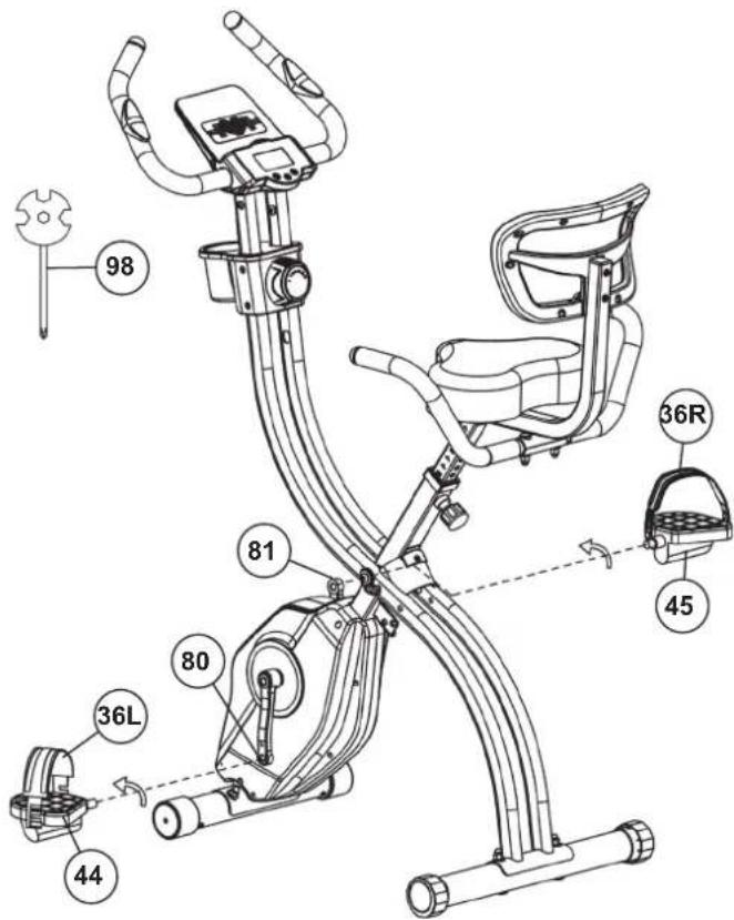
STEP 6
Installation of right and left pedal (44+45) at pedal cranks (80+81).
- The pedals and pedals straps are marked "R" for right and "L" for left.
- Screw the right pedal (45) into the threaded hole on the right hand side of the pedal crank (81) and tighten firmly. (Note: Right and left are specifies as viewed seated on the machine during training. It must also be observed that the threaded part of the right pedal must be screwed clockwise into the threaded hole of the pedal crank.)
- Screw the left pedal (44) into the threaded hole on the left hand side of the pedal crank (80) and tighten firmly. (Note: The threaded part of the left pedal have to screw anticlockwise into the threaded hole of the pedal crank.)
- Then mount the pedal straps on the left (36L) and right (36R) to the corresponding pedals (44+45). The small number of holes in the pedal straps should be attached to the inside of the pedal.
CHECKS
- Check the correct installation and function of all screwed and plug connections. Installation is thereby complete.
- When everything is in order, familiarise yourself with the machine at a low resistance setting and make your individual adjustments.
Note: Please keep the tool set and the instructions in a safe place as these may be required for repairs or spare parts orders becoming necessary later.
natural_image
Line drawing of a stationary exercise bike with adjustable arms and legs (no text or symbols)Function of the folding mechanism/Adjusting the training position:
-
To save space when storing the device, do not adjust the seat to the maximum position. Remove the locking pin (62) from the frame (2). This releases the lock, allowing you to fold the device by pushing the two base frames (1+2) together. After folding the device, push the locking pin (62) back into the lower opening.
-
Unfold the device in reverse order.
Adjustment – Seat Position
For an effective workout, the seat must be adjusted properly. While your are pedaling, your Knees should be slightly bent when the pedals are in the farthest position. In order to adjust the seat, unscrew the knob few turns and draw it out slightly. Adjust the seat to the right height, then release the knob and tighten it all the way.
Attention! Make sure to put the knob back into place in the seat post and tighten it completely. Never exceed the maximum height of the seat. Always get off the bicycle before making any adjustment.
Transportation
There are two rollers equipped on the front foot. For moving, you can lift up the rear foot and drive it to where you would like to locate or store it.
Mount
Hold onto the handlebar unit and step over the center of the base frame. Move a nearby pedal to the lowest position and slide your foot under the pedal locking strap so that you have a stable footing on the pedal. Sit on the seat and then place your other foot on the pedal under the pedal locking strap.
Use
Hold onto the handlebars or handle in the desired position with both hands and remain seated on the saddle during training. Pedal your exercise bike by your both feet alternately. Then you can increase the pedaling speed gradually and adjust braking resistance levels to increase the exercise intension.
Dismount
Stop training. Swing the handle backwards. Hold on tightly to the handlebars. Put your feet cross over the equipment and land on the floor, then land the other one.
This training equipment is a stationary exercise machine used to simulate without causing excessive pressure to the joints, hence decreasing the risk of impact injuries.
Exercise bike offer a non-impact cardiovascular workout that can vary from light to high intensity based on the resistance preference set by the user. It will strengthen your muscles of legs and increase cardio capacity and maintain fitness of your body also.
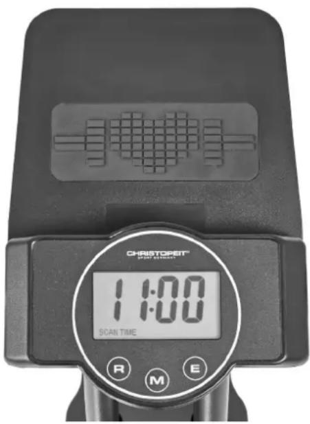
COMPUTERCOMPUTER INSTRUCTIONS
The supplied computer allows the most convenient training. Every value relevant to training is displayed in a corresponding window.
From the beginning of the training session, the required time, the current speed, the approximate calorie consumption, the travelled distance ad the current pulse rate are displayed. All values are counted from zero upwards. If you wish to see one value displayed constantly during training, select this with the [M] key. If you wish to see these values in constant alternation, select the „SCAN“ function. The display then changes from one function to the next at intervals of approx. 6 seconds. The computer is switched on by briefly pressing the [M] key or simply by beginning training. The computer begins to register and display all values.
To stop the computer, just stop training. The computer stops all measurements and retains the last attained values. The last attained values in the functions TIME, CALORIES and KM are stored for 4 minutes and training can continue with these values when training is resumed. The computer switches of automatically approx. 4 minutes after training is stopped.
DISPLAYS
[SCAN]:
If this function is selected, the current values of all functions are displayed successively in a constant sequence approx. every 5 seconds.
[SPD]:
The current speed is displayed in kilometres per hour. It is not possible to specify a particular value using the [E] key. The values last attained by this function are not stored. (Limit of the display: 999.9 km/h.)
[ DIST]:
The current status of the travelled distance is displayed. It is possible to specify a particular value using the [E] key. If a particular distance has been specified, the remaining distance is displayed. When the specified value is attained, this is indicated by an acoustic signal. The values last attained by this function are stored. (Limit of the display: 999,9 km.)
[TIME]:
The currently required time is displayed in minutes and seconds. It is possible to specify a particular value using the [E] key. If a particular time has been specified, the remaining time is displayed. When the specified value is attained, this is indicated by an acoustic signal. The values last attained by this function are stored. (Limit of the display: 99 minutes.)
[CAL]
The current status of the consumed calories is displayed. It is possible to specify a particular value using the [E] key. If a particular consumption has been specified, the remaining number of calories to be consumed is displayed. When the specified value is attained, this is indicated by an acoustic signal. The values last attained by this function are stored. (Limit of the display: 999,0 calories.)
[ODO]:
The current status of the travelled kilometres of all previous training sessions including current training session is displayed. The values last attained by this function are not stored. (Limit of the display: 9999 km.)
[PULSE]:
The current pulse rate is displayed in beats per minute. It is possible to specify a particular value using the [E] key. The values last attained by this function are not stored. (Limit of both displays: 80 - 180 pulse beats per minute.)
KEYS
1. [E-Enter]:
By pressing this key once, it is possible to specify values step by step in the respective functions. For this, the desired function must firstly be selected using the [M] key. Holding the key pressed activates faster running. When training begins, the specified values are then counted down to zero.
2. [M-Mode]:
Pressing this key once briefly makes it possible to change from one function to another, i.e. the respective functions can be selected for which entries can be made using the [E] key. The currently selected function is indicated in the window. If the key is held longer (approx. 3 seconds), all last attained values are deleted.
3. [R-Reset]
When this key is pressed briefly, the values chosen with the [M] key are reset to zero.
PULSE RATE
1. Hand pulse measurement
On the left and right side of handlebar two metal contact plates are insert as pulse sensors. Please take care that both hands at the same time in normal force on the sensors. During the heartbeat measurement a heart symbol flashes next to the pulse display. (The hand pulse measurement serves only for orientation, as it is caused by movement, friction, sweat etc. it can come to deviations from the actual pulse. A few people may cause malfunctions of hand pulse measurement. Should you have trouble with the hand pulse measurement, we recommend the use of a cardio chest belt with external pulse display.)
Attention! Heart rate monitor systems may be inaccurate. Excessive exercising can lead to serious damage or maybe to death. If dizziness or weakness is felt, stop exercising immediately.
REPLACING THE BATTERIES
- Open the battery compartment cover and then remove the used batteries.(If the batteries should leak remove them under increased considering that the battery acid is not into contact with skin come and clean the battery compartment thoroughly.)
- Insert the new batteries (type (AAA) 1.5 V in the correct order and taking into account the polarity in the battery compartment and close the battery cover so that it clicks into place.
- If the computer does not pick up immediately, the function should batteries are removed for 10 seconds and re-inserted.
- The empty batteries properly in accordance with the disposal regulations disposed of and do not give residual waste.
Battery compartment

natural_image
Diagram of two battery components with labeled parts, no text or symbols presentAAA Batteries
CLEANING, CHECKS AND STORAGE
1. Cleaning
Use only a less wet cloth for cleaning. Attention! Never use benzene, thinner or other aggressive cleaning agents for surface cleaning as this damage caused. The device is only for private home use and for use suitable indoors. Keep the unit clean and moisture from the device.
2. Storage
Plug out the power supply unit while intending the unit for more than 4 weeks not to use. Push the seat support tube as deeply as possible into the frame. Choose a dry storage in-house and put some spray oil to the pedal bearings left and right and on the thread of the quick release. Cover the bike to protect it from being discolor by any sunlight and dirty through dust.
3. Checks
We recommend every 50 hours to review the screw connections for tightness, which were prepared in the assembly. Every 100 operating hours, you should put some spray oil at the pedal bearings left and right, to the thread of quick releases.
TROUBLESHOOTING
If you cannot solve the problem with the following information, please contact the authorized service center.
| Problem Possible Cause Solution | ||
| Computer has no value at Display if you press any key. | No Batteries insert or batteries empty Check | the position of batteries at battery compartment or replace batteries. |
| Computer is not counting data and do not switch on after start cycling. | Sensor impulse missing base on not well plugged connection | Check the plug connections at computer and inside of handlebar support. |
| Computer is not counting data and do not switch on after start cycling. | Sensor impulse missing base on not correct position of sensor. | Take off the cover and check the distance between magnet and Sensor. The magnet at turning belt wheel should have only less than < 5mm distance against the sensor position. |
| No pulse value Pulse cable is not plugged in. Check the separately pulse cable is well connected with computer. | ||
| No pulse value Pulse sensors not well connected Screw out the screw for pulse | measurement and check if plugs are well connected and no damage at pulse cable.. | |
| Resistance don’t change Connect on of resistance not well Check the resistance connection inside of bottom unit. | ||
TRAINING SPACE REQUIREMENT
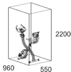
Training area in mm (for home trainer and user)
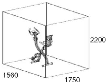
Free area in mm (Training area and security area (circulating 600mm))
GENERAL TRAINING INSTRUCTIONS
You must consider the following factors in determining the amount of training effort required in order to attain tangible physical and health benefits.
INTENSITY
The level of physical exertion during training must exceed the point of normal exertion, without going beyond the point of breathlessness and/or exhaustion. A suitable reference value can be the pulse. With each training session, the condition increases and therefore the training requirements should be adjusted. This is possible by extending the duration of the training, increasing the level of difficulty or changing the type of training.
TRAINING HEART RATE
To determine the training heart rate, you can proceed as follows. Please note that these are guide values. If you have health problems or are unsure, consult a doctor or fitness trainer.
01 Maximum heart rate calculation
The maximum pulse value can be determined in many different ways, since the maximum pulse depends on many factors. You can use the main-formula for the calculation (maximum heart rate = 220 - age). This formula is very general. It is used in many home sport products to determine the maximum heart rate. We recommend the Sally-Edwards-formula. This formula calculates the maximum heart rate more precisely and takes gender, age and body weight into account.
Sally-Edwards-formula:
Men:
Maximum heart rate = 214 - (0.5 x age) - (0.11 x body weight)
Women:
Maximum heart rate = 210 - (0.5 x age) - (0.11 x body weight)
02 Training heart rate calculation
The optimal training heart rate is determined by the goal of the training. Training zones were defined for this.
Health - Zone: Regeneration and Compensation
Suitable for: Beginners
Type of training: very light cardio training
Goal: recovery and health promotion. Building the basic condition.
Training heart rate = 50 to 60% of the maximum heart rate
Fat-Metabolism - Zone: Basics endurance training 1
Suitable for: beginners and advanced users
Type of training: light cardio training
Goal: activation of fat metabolism (calorie burning). improvement in endurance performance.
Training heart rate = 60 to 70% of the maximum heart rate
Aerobic - Zone: Basics endurance training 1 to 2
Suitable for: beginners and advanced
Type of training: moderate cardio training.
Goal: Activation of the fat metabolism (calorie burning), improving aerobic performance, Increase in endurance performance.
Training heart rate = 70 to 80% of the maximum heart rate
Anaerobic - Zone: Basics endurance training 2
Suitable for: advanced and competitive athletes
Type of training: moderate endurance training or interval training
Goal: improvement of lactate tolerance, maximum increase in performance.
Training heart rate = 80 to 90% of the maximum heart rate
Competition - Zone: Performance / Competition Training
Suitable for: athletes and high-performance athletes
Type of training: intensive interval training and competition training /
Goal: improvement of maximum speed and power.
Attention! Training in this area can lead to overloading of the cardiovascular system and damage to health.
Training heart rate = 90 to 100% of the maximum heart rate
Sample calculation
Male, 30 years old and weighs 80 kg. I am a beginner and would like to lose some weight and increase my endurance.
01: Maximum pulse - calculation
Maximum heart rate = 214 - (0.5 x age) - (0.11 x body weight)
Maximum heart rate = 214 - (0.5 x 30) - (0.11 x 80)
Maximum pulse = approx. 190 beats/min
02: Training heart rate calculation
Due to my goals and training level, the fat metabolism zone suits me best.
Training heart rate = 60 to 70% of the maximum heart rate
Training heart rate = 190 x 0.6 [60%]
Training heart rate = approx. 114 beats/min
After you have set your training heart rate for your training condition or Once you have identified goals, you can start training. Most of our endurance training equipment have heart rate sensors or are heart rate belt compatible. So you can check your heart rate on the monitor during the workouts. If the pulse rate is not shown on the computer display or you want to be on the safe side and want to check your pulse rate, which could be incorrectly displayed due to possible application errors or similar, you can use the following tools:
a. Pulse measurement in the conventional way (sensing the pulse beat, e.g. on the wrist and counting the beats within a minute).
b. Heart rate measurement with suitable and calibrated heart rate measuring devices (available from medical supply stores).
c. Heart rate measurement with other products such as heart rate monitors, smartphones....
FREQUENCY
Most experts recommend the combination of a health-conscious diet, which must be adjusted according to the training goal, and physical exercise three to five times a week. A normal adult needs twice a week exercise to maintain its current condition. To improve his condition and change his body weight, he needs at least three training sessions per week. Ideal of course is a frequency of five training sessions per week.
TRAINING PLAN
Each training session should consist of three training phases: "warmup phase", "training phase" and "cool-down phase". In the "warm-up phase" the body temperature and the oxygen supply should be increased slowly. This is possible through gymnastic exercises over a period of five to ten minutes. After that you start with actual training "training phase". The training load should be adapted according to the training heart rate. In order to support the circulation after the training phase and to preventaching or strained muscles later, it is necessary to follow the training phase with a cool-down phase. This should be consist of stretching exercises and/or light gymnastic exercises for a period of five to ten minutes.
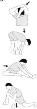
Example - stretching exercises for the warm-up and cool-down phases
Start your warm up by walking on the spot for at least 3 minutes and then perform the following gymnastic exercises to the body for the training phase to prepare accordingly. The exercises do not overdo it and only as far run until a slight drag felt. This position will hold a while.
natural_image
Sequence of four sequential illustrations showing a person performing a stretching or kneeling movement (no text or symbols)Reach with your left hand behind your head to the right shoulder and pull with the right hand slightly to the left elbow. After 20sec. switch arm.
Bend forward as far forward as possible and let your legs almost stretched. Show it with your fingers in the direction of toe. 2 x 20sec.
Sit down with one leg stretched out on the floor and bend forward and try to reach the foot with your hands. 2 x 20sec.
Kneel in a wide lunge forward and support yourself with your hands on the floor. Press the pelvis down. Change after 20 sec leg.
MOTIVATION
The key to a successful program is regular training. You should set a fixed time and place for each day of training and prepare yourself mentally for the training. Only train when you are in the mood for it and always have your goalin view. With continuous training you will be able to see how you are progressing day by day and are approaching your personal training goal bit by bit.
PARTS LIST – SPARE PARTS LIST
Type: Velo Fit
Order-Nr.: 2560
Date of technical data: 09.07.2025
Dimensions approx: [cm]: L 95 x B 55 x H 132 cm
Folded approx: [cm]: L 42 x B 55 x H 152 cm
Space requirements [m^2] : 2 m^2
Weight approx. [kg]: 22 kg
Load max. (User weight) [kg]: 120 kg
EIGENSCHAFTEN
• Magnetic brake system
• 14 -stepped resistance control
• Approx. 5 kg flywheel mass
- Foldable for space saving
• Height adjustable seat with back mesh cushion
• Additional handgrip
- Hand pulse measurement
• Floor level compensation and transport rollers
- Computer with LCD display shows: Time, Speed, Distance, ODO, approx. calories and pulse frequency.
- Integrated holder for smartphones and tablets
NOTE
Please contact us if any components are defective or missing, or if you need any spare parts or replacements in future.
This product is created only for private Home sports activity and not allowed to us in a commercial or professional area. Home Sport use class H/C.
| Illustration No. | Designation Dimension mm Quantity Attached to ET Number | ||||
| 1 Front frame 1 60 33-2560-01-SW | |||||
| 2 Main frame 1 2 33-2560-02-SW | |||||
| 3 Front stabilizer 1 3 33-2560-03-SW | |||||
| 4 Rear stabilizer 1 2 33-2560-04-SW | |||||
| 5 Seat support 1 60 33-2560-05-SW | |||||
| 6 Backrest support 1 5 33-2560-06-SW | |||||
| 7 Spring washer for M8 12 41,46+98 | 39-9864-SW | ||||
| 8 Hand grip | 1 6 33-2560-07-SW | ||||
| 9 Left handlebar support | 1 2+11 | 33-2560-08-SW | |||
| 10 Right handlebar support | 1 | 2+11 | 33-2560-09-SW | ||
| 11 Handlebar | 1 | 9+10 | 33-2560-10-SW | ||
| 12 Handlebar foam | 2 | 11 | 36-2560-10-BT | ||
| 13 Round cap | 4 8+11 | 36-9988-32-BT | |||
| 14 Pulse sensor with wire | 2 | 11 | 36-2560-11-BT | ||
| 15 Phillips screw | 4.2x20 | 3 | 14+27 | 39-10253-VC | |
| 16 Phillips screw | M5x10 | 4 | 11,18,69+70 | 39-9903-SW | |
| 17 Computer | 1 11+18 | 36-2560-03-BT | |||
| 18 Computer backside | 1 17 36-2560-04-BT | ||||
| 19 Phillips screw | 3.6x15 | 4 18 39-10190 | |||
| 20 Allen bolt | M6x12 | 10 | 9+10 | 39-9958 | |
| 21 Curved washer | 6//14 | 6 20 39-9863 | |||
| 22 Washer | 6//12 | 12 | 20,35+63 | 39-10013-VC | |
| 23 Connection cable 2 | 1 | 17+29 | 36-2560-05-BT | ||
| 24 Cable safe | 1 10 36-9821-13-BT | ||||
| 25 Drink holder | 1 | 9,10,26+27 | 36-2560-15-BT | ||
| 26 Drink holder cover left | 1 27 36-2560-14-BT | ||||
| 27 Drink holder cover right | 1 26 36-2560-13-BT | ||||
| 28 Phillips screw | 4.2x15 | 8 | 26,27,78+79 | 36-9825339-BT | |
| 29 Connection cable 1 | 1 | 23+70 | 36-2560-06-BT | ||
| 30 Seat | 1 5 36-2560-08-BT | ||||
| 31 Washer | 8//16 | 11 | 30,39+53 | 39-9962-SW | |
| 32 Nylon nut | M8 | 3 30 39-9918-CR | |||
| 33 Back cushion | 1 6 36-2560-12-BT | ||||
| 34 Square cap | 1 6 36-9904-17-BT | ||||
| 35 Allen bolt | M6x40 | 2 | 6+33 | 36-10452-SW | |
| 36L Pedal strap left | 1 44 36-9308-12-BT | ||||
| 36R Pedal strap right | 1 45 36-9308-10-BT | ||||
| 37 Cap nut | M8 | 8 | 39,41+46 | 39-9900-SW | |
| 38 Magnet | 1 75 36-9101-14-BT | ||||
| 39 Carriage bolt M8x45 2 6 39-9953 | |||||
| Illustration No. | Designation Dimension mm Quantity Attached to ET Number | |||||
| 40 Handgrip | foam 2 8 36-2560-16-BT | |||||
| 41 Allen bolt | M8x40 2 8 39-9817 | |||||
| 42 Curved washer | 8//20 8 41+46 39-10247 | |||||
| 43 Quick release M16 1 1 36-1260-09-BT | ||||||
| 44 Pedal left 9/16" 1 80 | 33-1107-14-BT | |||||
| 45 Pedal right | 9/16" 1 81 | 33-1107-15-BT | ||||
| 46 Carriage bolt | M8x60 4 3+4 | 39-10094 | ||||
| 47 Eccentric cap | 2 4 36-1321-07-BT | |||||
| 48 End cap with transport roller | 2 3 36-2561-10-BT | |||||
| 49 Phillips screw | 4.2x20 2 48 | 39-10253-VC | ||||
| 50 Seat support holder | 1 1 33-2560-17-SW | |||||
| 51 Bushing | 1 50 | 36-2560-17-BT | ||||
| 52 Plastic sleeve | 6 2+50 | 36-2402-09-BT | ||||
| 53 Hex screw | M8x20 6 1+60 | 39-10095-CR | ||||
| 54 Allen bolt | M8x20 2 61 | 39-10247 | ||||
| 55 Wire plug | 3 2+50 | 36-2560-18-BT | ||||
| 56 Resistance adjustment | 1 2 36-2560-09-BT | |||||
| 57 Washer | 5//15 | 1 | 58 | 39-10111-SW | ||
| 58 Phillips screw | M5x25 1 56 | 36-9825233-BT | ||||
| 59 Rubber buffer | 1 2 36-2560-19-BT | |||||
| 60 Washer | 8//25 2 54 | 39-10018-CR | ||||
| 61 Axle | 1 2 33-2560-11-SI | |||||
| 62 Safety pin | 1 1+2 | 36-2560-20-BT | ||||
| 63 Phillips screw | M6x12 6 64 | 39-10120-VC | ||||
| 64 Cover Plate | 2 67 | 33-2560-18-SI | ||||
| 65 C clip | C 17 | 6 75 | 36-9504-20-BT | |||
| 66 Ball bearing | 6003ZZ | 4 67+68 36-1260-36-BT | ||||
| 67 Plastic bearing seat | 2 64+66 36-2560-21-BT | |||||
| 68 Flywheel | 1 66 | 33-2560-12-SI | ||||
| 69 Magnetic bracket | 1 1+56 | 33-2560-20-SI | ||||
| 70 Sensor cable | 1 1+29 | 36-2560-07-BT | ||||
| 71 Washer | 5//12 | 1 | 16 | 39-10011 | ||
| 72 Spring | 1 69 | 36-2560-22-BT | ||||
| 73 Nut | M6 | 3 74+93 39-9861-VZ | ||||
| 74 Hex bolt | M6x20 1 69 | 39-10128 | ||||
| 75 Pedal axle with pulley | 1 66 | 33-2560-13-SW | ||||
| 76 Belt | 240J | 1 75+90 36-2460-12-BT | ||||
| 77 Belt | 230J | 1 68+90 36-2402-11-BT | ||||
| 78 Cover left | 1 1+79 | 36-2560-01-BT | ||||
| 79 Cover right | 1 1+78 | 36-2560-02-BT | ||||
| 80 Pedal crank left | 9/16" 1 45+75 33-2560-14-SI | |||||
| 81 Pedal crank right | 9/16" 1 44+75 33-2560-15-SI | |||||
| 82 Axle nut | M10x1.25 | 2 75 | 39-9820-SW | |||
| 83 Crank Cap | 2 80+81 36-9119-31-BT | |||||
| 84 Phillips screw | 4.2x25 6 78+79 39-9825338-BT | |||||
| 85 Phillips screw | M5x10 1 88 | 39-9903-SW | ||||
| 86 Washer | 5//18 1 85 | 39-9863 | ||||
| 87 Ball bearing | 6202 1 88 | 36-1965-18-BT | ||||
| 88 Idle wheel axle | 1 1 33-2560-16-SI | |||||
| 89 Nut | M10 1 88 | 33-9981-VC | ||||
| 90 Transmission wheel | 1 | 92 | 36-2560-23-BT | |||
| 91 Ball bearing | 6000 2 90 | 39-9998 | ||||
| 92 Transmission axle | 1 1 33-2560-19-SI | |||||
| 93 Eye bolt | M6x35 2 92 | 39-10000 | ||||
| 94 Axle nut | M10x1.0 | 2 94 | 36-1721-12-BT | |||
| 95 C clip | C10 | 1 92 | 36-1826-16-BT | |||
| 96 Axle nut small | M10x1.0 | 1 92 | 39-9820 | |||
| 97 Open end wrench | 1 | 36-2466-16-BT | ||||
| 98 Multi wrench | 1 | 36-9107-28-BT | ||||
| 99 Allen tool | 5 | 1 | 36-9119-34-BT | |||
| 100 Allen tool | 6 | 1 | 36-9107-27-BT | |||
| 101 Assembly and exercise instruction | 1 | 36-2560-24-BT | ||||
SOMMAIRE
Page Contenu

ETAPE 6
natural_image
Line drawing of a stationary exercise bike with adjustable arms and legs (no text or symbols)MONTER, UTILISER & DESCENDRE
COMPUTERCOMPUTER INSTRUCTIONS
TOUCHES
1. [E-Enter]:
REEMPLACEMENT DES PILES:
natural_image
Technical line drawing of a battery pack and its internal components (no text or symbols)NETTOYAGE, ENTRETIEN ET STOCKAGE DE L'EXERCICE
1. Nettoyage
natural_image
3D diagram of a stationary bike inside a cube with dimension labels (1560, 1750, 2200) and no readable text or symbols beyond measurement markers.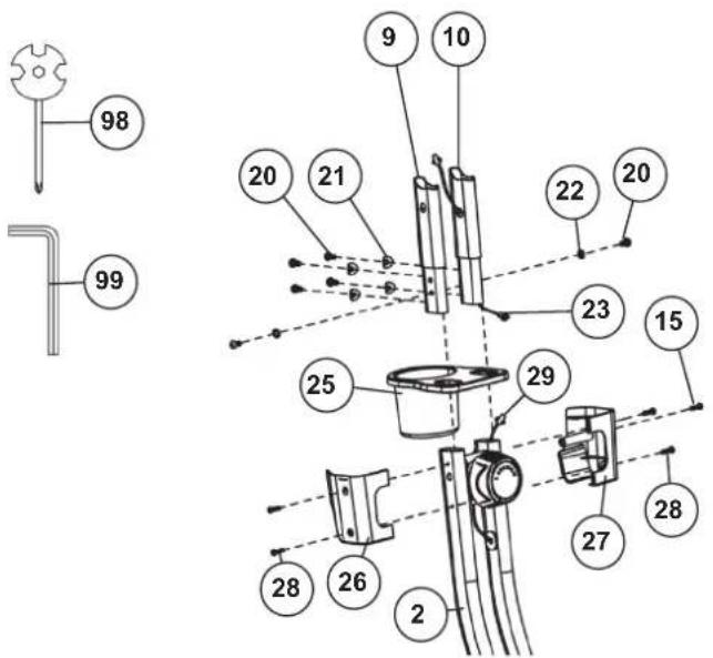
STAP 4
STAP 6
natural_image
Line drawing of a stationary exercise bike with adjustable arms and legs (no text or symbols)OPSTAPPEN, GEBRUIKEN & AFSTAPPEN
COMPUTERHANLEIDING
natural_image
Diagram of two battery components with no text or symbolsREINIGING, ONDERHOUD EN OPSLAG
1. Schoonmaak
Competitie - Zone: Prestaties / Competitie Training
02: Training hartslagberekening
natural_image
Sequence of four sequential illustrations showing a person performing a stretching or kneeling movement (no text or symbols)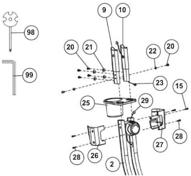

KROK 4
KROK 5
natural_image
Line drawing of a stationary exercise bike with adjustable arms and legs (no text or symbols)POUŽÍVÁNÍ PŘÍSTROJE
POKYNY K POČÍTAČI
UKÁZAT
[SCAN]:
natural_image
Diagram of two electronic components: a battery pack and a cylindrical battery, with no visible text or symbols.AAA Baterie
ČISTĚNÍ, KONTROLA A SKLADOVÁNÍ DOMÁCÍHO
1. Čistění
natural_image
Sequence of four sequential illustrations showing a person performing a stretching or kneeling movement (no text or symbols)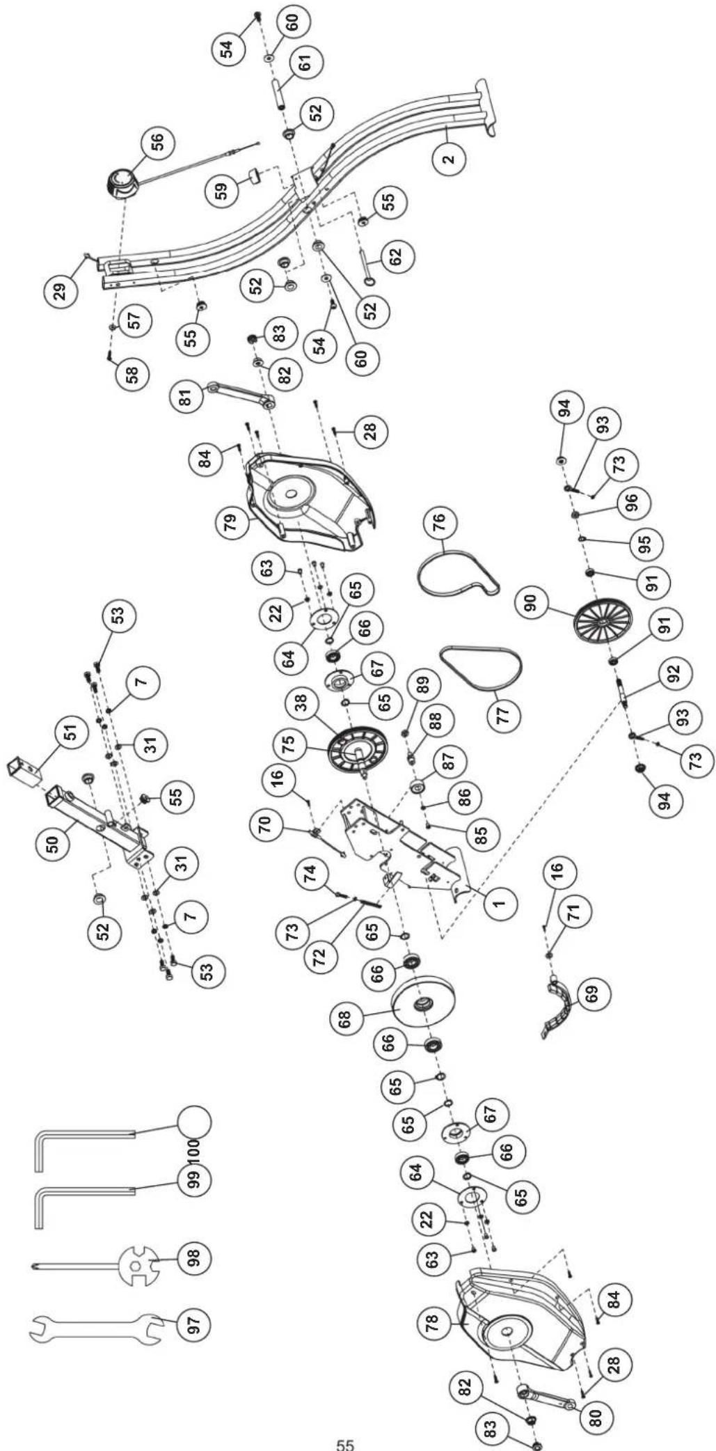
© by Top-Sports Gilles GmbH D-42551 Velbert (Germany)