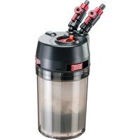
Prime 10 - Aquarium filter Ferplast - Free user manual and instructions
Find the device manual for free Prime 10 Ferplast in PDF.


| Product type | External aquarium filter |
| Brand | Ferplast |
| Model | Prime 10 |
| Self-priming | Yes, automatic system with priming cap |
| Filter media included | Yes |
| Shut-off valves | Yes, with red safety latch |
| Maximum water temperature | 35 °C |
| Installation type | Below water level (priming), then possible at same level |
| Intake pipe | Included, with extension tube, strainer, and priming clip |
| Outflow pipe | Included, with adjustable nozzle |
| Spray bar | Optional (US version included, otherwise optional) |
| Flexible hoses | Included, to be cut to desired length |
| Recommended maintenance | Regular cleaning of filter media, impeller, and priming chamber |
| Prohibited cleaning products | Detergents and abrasives (warm water only) |
| Safety | Disconnect all devices before working in the aquarium |
| Power cable | Non-replaceable – replace the device if damaged |
| Usage | Indoor only, for freshwater or saltwater aquarium |
| Warranty | Manufacturing defects (excludes wear, foam, seals) |
| Spare parts available | Sealing gasket, impeller, filter basket (not covered by warranty) |
| Main material | Plastic |
Frequently Asked Questions - Prime 10 Ferplast
User questions about Prime 10 Ferplast
0 question about this device. Answer the ones you know or ask your own.
Ask a new question about this device
Download the instructions for your Aquarium filter in PDF format for free! Find your manual Prime 10 - Ferplast and take your electronic device back in hand. On this page are published all the documents necessary for the use of your device. Prime 10 by Ferplast.
USER MANUAL Prime 10 Ferplast
Aquarium external filter
Prime 10
Prime 20
Prime 30
User's Guide
natural_image
Black-and-white photo of multiple industrial vacuum cleaner units with coiled pipes and fittings, no visible text or symbols.EN. The Safety instructions shall be read before using the appliance.
A1 Sloping rotatable fittings
A2 Tap
A3 Safety locking button
A4 Clip
A5 Impeller assembly
A6 Fixed O-ring (for models Prime 20 and Prime 30 only)
A7 Pump chamber
A8 Priming chamber
B VALVE TAPS
C FILTER UNIT
C1 Filter media container
C2 Filter body
C3 Antislip rubber feet
D INTAKE UNIT
D1 Collector tube
D2 Extension tube
D3 Locking nut
D4 Priming clip
D5 Strainer
E OUTLET UNIT
E1 Collector tube
E2 Nut
E3 Multi-directional diffuser
F SPRAY BAR
F1 Support tube
F2 Elbow coupling
F3 Suction clip
F4 Plug
G FLEXIBLE PIPES
Deutsch
C3 Rubberen anti-slip poten
D AANZUIGBUIS
D1 Buis
D2 Verlengbuis
D3 Bevestigingsring
D4 Activering klem
D5 Crepine
E OVERLOOPBUIS
E1 Buis
E2 Bevestigingsring
E3 Beweegbare overlooptube
F SPRAY BAR
natural_image
3D illustration of a cabinet with two labeled containers, one containing a brush and the other inside (no text or symbols)fig 2 fig 3
natural_image
Diagram of a mechanical setup with pipes and a cylindrical component inside a container (no text or symbols)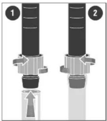
natural_image
Two mechanical components with directional arrows indicating movement or force, no text or symbols present
fig 4 fig 5
natural_image
Illustration of three microscope units mounted on a base, showing mechanical components (no text or symbols)fig 6 fig 7
natural_image
Illustration of three microscope funnels with no visible text or symbols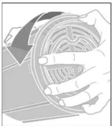
natural_image
Illustration of hands holding a circular mechanical component (no text or symbols visible)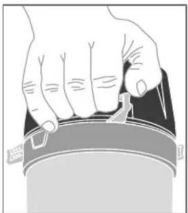
natural_image
Illustration of a hand pressing down on a cylindrical object (no text or symbols visible)fig 8 fig 9
natural_image
Cross-sectional diagram of a mechanical or electrical component with no visible text or symbolsfig 10
natural_image
Abstract diagram of a mechanical or fluidic process with curved arrows indicating flow or movement (no text or symbols)fig 11
natural_image
Illustration of a hand using a magnifying glass to measure a liquid in a microscope (no text or symbols)fig 12
natural_image
Diagram of a pipeline system with valves and flow indicators (no text or symbols)fig 13
natural_image
Abstract illustration of a hand pressing down on a curved mechanical component with directional arrows (no text or symbols)fig 14
natural_image
Illustration of a hand turning a mechanical component with a gear and shaft (no text or symbols)fig 15
Contents
English pag 10
Deutsch pag 12
Français pag 15
Español pag 19
Italiano pag 21
Nederlands pag 24
Português pag 27
Svenska pag 30
Polski pag 33
Magyar pag 35
Русский pag 38

WARNINGS
- This appliance is intended for indoor use only and for use in fluids up to 35°C.
- Be sure that the voltage of the mains supply corresponds to the voltage shown on the label of the unit.
- Before connecting to mains supply be sure that the cord and the unit are undamaged.
- The cord of this unit cannot be replaced or repaired; in case of damage it will be necessary to change the whole unit.
- This appliance is not intended for use by persons (including children) with reduced physical, sensory or mental capabilities, or lack of experience and knowledge, unless they have been given supervision or instruction concerning use of the appliance by a person responsible for their safety.
- Children should be supervised to ensure that they do not play with the appliance.
- Installation shall be performed in accordance with national wiring rules.
- Always disconnect all electrical equipment from the electricity supply, installed both inside and outside your aquarium, before putting your hands in the water.

EUROPEAN UNION DISPOSAL INFORMATION
Within the European Union, a crossed-out wheelie bin symbol on the product, documentation or packaging indicates that the product cannot be disposed of in
the regular household waste stream, in compliance with EU Directive 2012/19/EC and with current local regulations. The product must be disposed of at recycling centres or authorised waste disposal centres for electrical and electronic equipment, in accordance with current legislation in the country where the product is found. Incorrect disposal of this type of waste can have a negative impact on the environment and human health, caused by the potentially hazardous substances produce by electrical and electronic equipment. Correct disposal of these products will also contribute to the efficient use of natural resources. Further information is available from the product retailer, the competent local authorities and national manufacturer's organisations.
PRIME external filter
Dear Fishkeeper,
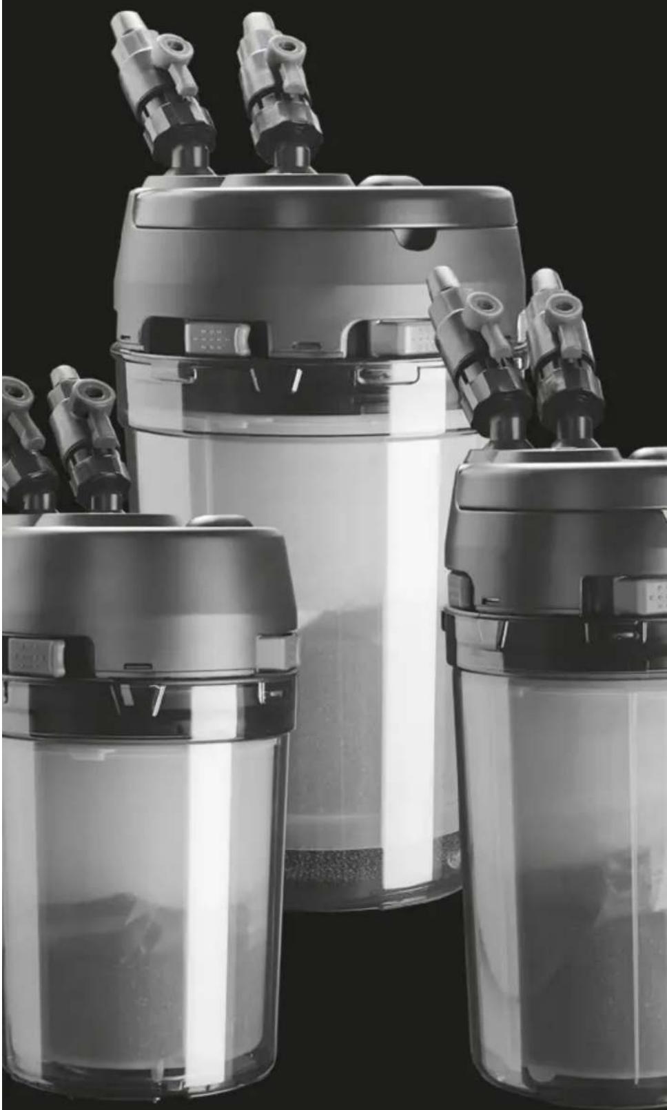
thank you for choosing this quality product. PRIME is the first external self-priming power filter with automatic priming chamber equipped with safety tap. Please read the instructions carefully, you will then appreciate the filters unique features and characteristics and you will be able to use PRIME at its best.
INSTALLATION
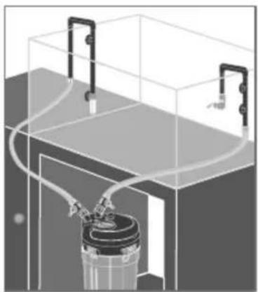
Whilst priming the filter, PRIME must be located below the aquarium level -Fig. 2-. If you wish to place the unit at the side of the aquarium, you must do so only after priming it.
PREPARING THE FILTER
- Choose the most suitable location for the inlet and outlet systems and install them with the locking nuts on the outside of the tank. It is suggested that the intake and outlet units should
be mounted close to the rear corners, at opposite ends -Fig. 3-.
- The suction unit can be lengthened by inserting the extension tube between the priming clip and the prefilter, cutting it to the required size. If the aquarium does not need an extension tube, connect the prefilter directly to the priming clip
- Adjust the maximum height of the outlet unit as indicated by "MAX. WATER LEVEL" and cut off any excess tubing -Fig. 4-. Both the connector tubes must be fixed to the walls of the tank by means of the suction cups provided.
- Cut the flexible tubes to the most convenient length, the cut must be at 90° to the tube wall and as neat as possible. Connect the tubes to the inlet and outlet systems, as straight as possible without kinks or twists, fixing them with the locking nuts following the procedure as shown in -Fig. 5-.
- For the first 24 hours of operation it is advisable to check the closure of the connections and of the nuts.
MOUNTING THE SPRAY BAR (FOR US VERSION ONLY)
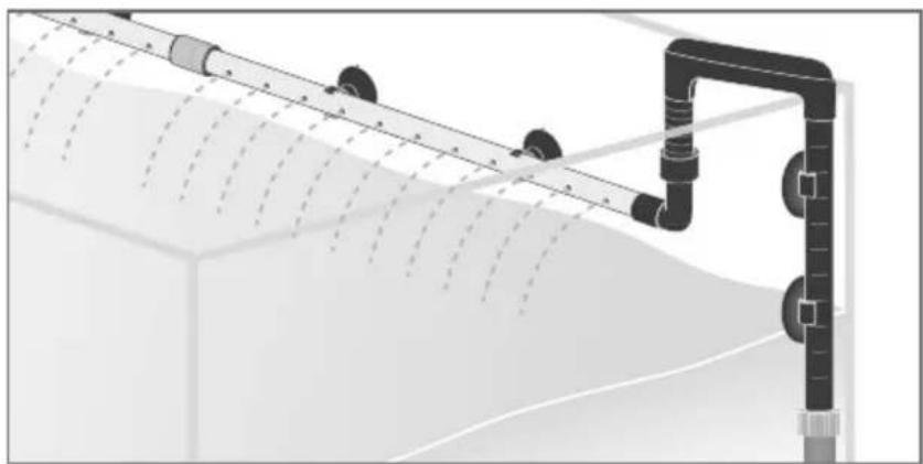
On the delivery unit, it is possible to apply the spray bar, a sort of hollow tube that improves oxygenation -Fig. 13 - available only on North American models and optional in the rest of the world.
- Insert the plug into the opposite end of the tube of the spray bar.
- Cut the inside part of the delivery unit so that the spray bar is positioned near the surface of the water.
- Connect the elbow coupling to the delivery unit and then to the tube.
- Use the suction clips provided to fix the tube to the rear wall of the aquarium so it is positioned correctly.
FITTING THE VALVE TAPS
Attention: to avoid the inconvenient siphoning effect which can empty the aquarium whilst it is being maintained, PRIME is equipped with special valve taps to ensure a perfect shut-off of the connecting tubes. Their unique design allows their release only in the OFF position.
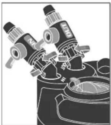
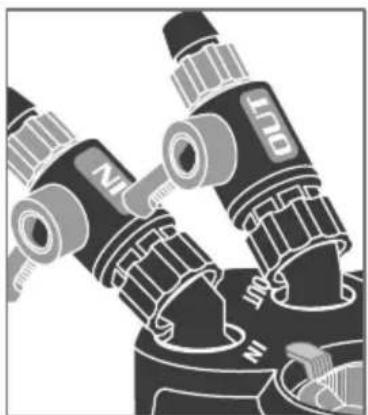
Screw the valves tightly on to the sloping rotatable fittings protruding from the pump assembly -Fig. 6-. Connect the flexible tubes to the valves following the same procedure used to connect them to the collectors tubes.
Attention: connect the outlet tube with the filter exit marked "OUT" and the intake tube to the filter inlet marked "IN"-Fig. 7-.
PLACEMENT OF THE FILTER MEDIA
- Rotate the clips unlocking the pump assembly and open the filter by levering on the special slots using your fingers -Fig. 8-.
- Remove the filter media container and open it by unscrewing the cover in an anticlockwise direction -Fig. 9-. If the product is supplied with filter media, it will be located inside the container.
- Remove the media from their plastic bags, rinse under water, and pour them in the net bags. If the product is supplied without filter media, fill the container with the chosen materials. Rinse the filter media before using them.
- Close the container very carefully screwing the cover in a clockwise direction and replace it in the filter.
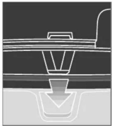
- Reassemble the pump assembly, paying attention to the correct position of the reference marks -Fig. 10-, ensure the clips are in open position since forcing the unit in with these closed will split the canister. Make sure the pump assembly is properly seated in the filter unit and close the clips until they click into position. Check that the inlet and outlet systems, the valves and nuts are all locked tightly. Open the valve taps by rotating the levers.
STARTING THE FILTER
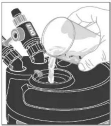
The PRIME external filter is self-priming: it is sufficient to pour the water required for the specific Prime model (see technical data table) into the priming chamber, and when it is connected to the mains it will start functioning automatically.
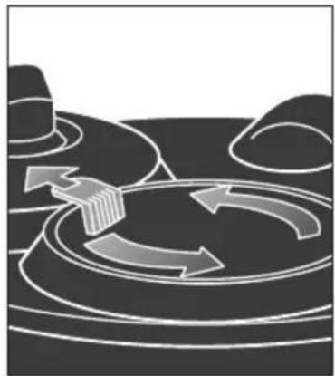
- By pressing the red button in the direction of the "arrow" engraved on it, unscrew the priming
- tap and remove it -Fig. 11-.
• Fill up the priming chamber -Fig. 12-.
- Replace the tap and carefully twist it clockwise, until the red button relocates into position.
- Connect PRIME to mains supply, it will start automatically and all the air inside the filter body and the tubes will be discharged through the impeller chamber. It is normal a certain amount of noise due to the presence of air in the ducts until all the air is discharged. It may take a short time for the filter to fully prime. Once the filter is running, the noise will disappear and PRIME will work quietly and at its best.
MAINTENANCE
Attention: always disconnect all electrical equipment from the electricity supply, installed both inside and outside your aquarium, before putting your hands in the water.
- Shut off both valves, unscrew them and remove them from the filter by pulling them off the filter.
- Attention: the valve taps must remain attached to the flexible tubes.
- It is normal for a very small amount of water inside the valves to be discharged, this does not indicate faulty functioning of the valve taps. Place the filter body in a bowl to allow you to open up the unit without fear of spillage.
- Open the clips until they click out of the locking position and take apart the pump assembly from the filter by levering on the special slots -Fig. 8-.
- Pull out the filter media container by its handle and open by unscrewing the cover -Fig. 9-.
- To avoid destroying the colonies of bacteria in the substrate of the filter, it is recommended to wash or to replace only one part of the filter media at one time.
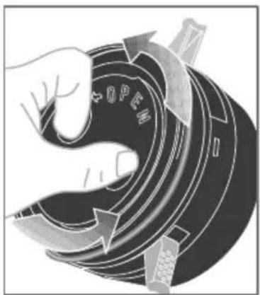
- Close the container very carefully screwing the cover in a clockwise direction and replace it in the filter. Every time the filter media is cleaned it is recommended that the rotor impeller assembly is cleaned together with its chamber, priming chamber and all the water ducts. Remove the priming chamber from the pump by unscrewing it -Fig. 14-.
- By pressing the red button in the direction of the "arrow" engraved on it, unscrew the priming tap -Fig. 11-.
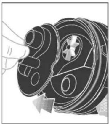
- Remove the pump chamber pulling it from its top -Fig. 15-. Remove the impeller from its seating.
- Use a stiff brush clean carefully to remove all deposits and wash well under running water.
- Attention: do not use solvents or detergents of any kind.
• Reassemble the whole unit in reverse order. - For the models PRIME 20 and PRIME 30 ensure the "O" ring is in place. If necessary clean all the deposits from the collectors, intake and outlet system and flexible tubes. For this operation it is suggested that you use the special brushes available at your dealers.
- Replace PRIME as described under "INSTALLATION", connect the valve taps, open the levers by rotating them into the in-line position. Check the tightness of all nuts and connections and re-prime the filter as described under "STARTING THE FILTER".
GUARANTEE
This product, all its parts and accessories are covered by warranty within the limits provided for in this paragraph and the legal regulations currently in force. The guarantee only covers manufacturing defects and includes the repair or replacement of the product free of charge. The guarantee does not cover damage and/or defects caused by carelessness, wear, unsuitable usage not complying with the instructions and warnings in this manual, accidents, tampering, incorrect use, bad repair work or purchases not accompanied by a fiscal receipt.

SICHERHEITSINWEISE
MISE EN PLACE DES ROBINETS
MONTAGEM SPRAY BAR (APENAS PARA VERSÃO US)
* Flowrate of the filter measured with media, hoses, U connections, valves, etc.
** Self priming is the amount of water needed to start the filter.
| Model | ||||||||||||||||||||||||||||||||||||||||||||||||||||||||||||||||||||||||||||||||||||||||||||||||||||||||||||||||||||||||||||||||||||||||||||||
| Power | Aquariums | |||||||||||||||||||||||||||||||||||||||||||||||||||||||||||||||||||||||||||||||||||||||||||||||||||||||||||||||||||||||||||||||||||||||||||||
| Filter Circulation* | ||||||||||||||||||||||||||||||||||||||||||||||||||||||||||||||||||||||||||||||||||||||||||||||||||||||||||||||||||||||||||||||||||||||||||||||
| Pump Out | ||||||||||||||||||||||||||||||||||||||||||||||||||||||||||||||||||||||||||||||||||||||||||||||||||||||||||||||||||||||||||||||||||||||||||||||
| Filter Circulation* | ||||||||||||||||||||||||||||||||||||||||||||||||||||||||||||||||||||||||||||||||||||||||||||||||||||||||||||||||||||||||||||||||||||||||||||||
| Pump Out | Head max | Filtering volume | Self Priming** |
110-120 V\~60 Hz
| PRIME 10 | 8 W | 22 - 40 gal80 - 150 l | 100 gph380 l/h | 170 gph640 l/h | 39.4 in100 cm | 1.6 qt1,5 l | 8.4 oz250 ml |
| PRIME 20 | 17 W | 26 - 66 gal100 - 250 l | 190 gph720 l/h | 240 gph910 l/h | 63.0 in160 cm | 3.2 qt3 l | 10.1 oz300 ml |
| PRIME 30 | 33 W | 53 - 120 gal200 - 450 l | 280 gph1060 l/h | 420 gph1590 l/h | 90.6 in230 cm | 5.3 qt5 l | 11.8 oz350 ml |
* Flowrate of the filter measured with media, hoses, U connections, valves, etc.
** Self priming is the amount of water needed to start the filter.
For marine tanks or higher filtering capacity select the next model up from the suggested aquarium size.
Stamp and signature of seller

- Deutsch
- Contents
- WARNINGS
- EUROPEAN UNION DISPOSAL INFORMATION
- PRIME external filter
- INSTALLATION
- PREPARING THE FILTER
- MOUNTING THE SPRAY BAR (FOR US VERSION ONLY)
- FITTING THE VALVE TAPS
- PLACEMENT OF THE FILTER MEDIA
- STARTING THE FILTER
- MAINTENANCE
- GUARANTEE
- SICHERHEITSINWEISE
- MISE EN PLACE DES ROBINETS
- MONTAGEM SPRAY BAR (APENAS PARA VERSÃO US)
Brand : Ferplast
Model : Prime 10
Category : Aquarium filter