
ZEUS51E - Uninterruptible power supply Equip - Free user manual and instructions
Find the device manual for free ZEUS51E Equip in PDF.

| Product Type | Uninterruptible Power Supply (UPS) |
| Brand | Equip |
| Model | ZEUS51E |
| Mounting Type | 19-inch Rack (2U) or vertical tower |
| AC Input | Grounded mains plug, circuit breaker protection, max current 10 A (1K/2K) or 16 A (3K) |
| Output Outlets | Battery-powered and surge-protected outlets |
| Protection | Surge protection, overload, short circuit, overheat |
| Display | Multifunction LCD screen with navigation buttons |
| Communication | USB port, RS232 port, SNMP/HTTP slot (optional card) |
| Management Software | Power Master+ (downloadable from official website) |
| EPO Connector | Remote emergency stop |
| External Battery Connector | For extended autonomy module |
| Battery | Sealed lead-acid, maintenance-free |
| Safety | Mandatory grounding; do not use for medical equipment or near aquariums |
| Cleaning | Unplug the device and wipe with a dry, lint-free cloth |
| Included Spare Parts | Power cables (EU/UK), USB cable, RS232 cable, mounting brackets, screws, dust covers |
| Repairability | No user-serviceable parts; maintenance by qualified personnel |
| Certifications | CE |
| Operating Temperature | 0 to 40 °C (estimated) |
| Operating Humidity | 20 to 80% non-condensing (estimated) |
Frequently Asked Questions - ZEUS51E Equip
User questions about ZEUS51E Equip
0 question about this device. Answer the ones you know or ask your own.
Ask a new question about this device
Download the instructions for your Uninterruptible power supply in PDF format for free! Find your manual ZEUS51E - Equip and take your electronic device back in hand. On this page are published all the documents necessary for the use of your device. ZEUS51E by Equip.
USER MANUAL ZEUS51E Equip
This Quick Installation Guide provides essential information for basic setup. For detailed instructions and additional features, please refer to the comprehensive user manual available for download on the Conceptronic website: www.conceptronic.net. Please read and follow all instructions carefully during installation and operation of the unit. Read this manual thoroughly before attempting to unpack, install, or operate the UPS.
CAUTION! The UPS must be connected to a grounded AC power outlet with fuse or circuit breaker protection. DO NOT plug the UPS into an outlet that is not grounded. If you need to power-drain this equipment, turn off and unplug the unit.
CAUTION! The battery can power hazardous components inside the unit, even when the AC input power is disconnected.
CAUTION! The UPS should be placed near the connected equipment and easily accessible.
CAUTION! To prevent the risk of fire or electric shock, install in a temperature and humidity controlled indoor area, free of conductive contaminants. (Please see specifications for acceptable temperature and humidity range).
CAUTION! (No User Serviceable Parts): Risk of electric shock, do not remove cover. No user serviceable parts inside. Refer servicing to qualified service personnel.
CAUTION! (Non-Isolated Battery Supply): Risk of electric shock, battery circuit is not isolated from AC power source; hazardous voltage may exist between battery terminals and ground. Test before touching.
CAUTION! To reduce the risk of fire, connect the UPS to a branch circuit with 10 amperes (1K / 2K) / 16 amperes (3K) maximum over-current protection in accordance to CE requirement.
CAUTION! The AC outlet where the UPS is connected should be close to the unit and easily accessible.
CAUTION! Please use only VDE-tested, CE-marked mains cable, (e.g. the mains cable of your equipment), to connect the UPS to the AC outlet.
CAUTION! Please use only VDE-tested, CE-marked power cables to connect any equipment to the UPS.
CAUTION! When installing the equipment, ensure that the sum of the leakage current of the UPS and the connected equipment does not exceed 3.5mA.
CAUTION! Do not unplug the unit from AC Power during operation, as this will invalidate the protective ground insulation.
CAUTION! To avoid electric shock, turn off and unplug the unit before installing the input/output power cord with a ground wire. Connect the ground wire prior to connecting the line wires!
CAUTION! Do not use an improper size power cord as it may cause damage to your equipment and cause fire hazards.
CAUTION! Wiring must be done by qualified personnel.
CAUTION! DO NOT USE FOR MEDICAL OR LIFE SUPPORT EQUIPMENT!
Under no circumstances this unit should be used for medical applications involving life support equipment and/or patient care.
CAUTION! DO NOT USE WITH OR NEAR AQUARIUMS! To reduce the risk of fire, do not use with or near aquariums. Condensation from the aquarium can come in contact with metal electrical contacts and cause the machine to short out.
CAUTION! Do not dispose of batteries in fire as the battery may explode.
CAUTION! Do not open or mutilate the battery, released electrolyte is harmful to the skin and eyes.
CAUTION! A battery can present a risk of electric shock and high short circuit current. The following precaution should be observed when working on batteries
-
Remove watches, rings or other metal objects.
-
Use tools with insulated handles.
CAUTION! The unit has a dangerous amount of voltage. When the UPS indicators is on, the units may continue to supply power thus the unit's outlets may have a dangerous amount of voltage even when it's not plugged in to the wall outlet.
CAUTION! Make sure everything is turned off and disconnected completely before conducting any maintenance, repairs or shipment.
CAUTION! Connect the Protection Earth (PE) safety conductor before any other cables are connected.
WARNING! (Fuses): To reduce the risk of fire, replace only with the same type and rating of fuse.
DO NOT INSTALL THE UPS WHERE IT WOULD BE EXPOSED TO DIRECT SUNLIGHT OR NEAR A STRONG HEAT SOURCE!
DO NOT CONNECT DOMESTIC APPLIANCES SUCH AS HAIR DRYERS TO UPS OUTPUT SOCKETS!
SERVICING OF BATTERIES SHOULD BE PERFORMED OR SUPERVISED BY PERSONNEL KNOWLEDGE OF BATTERIES AND THE REQUIRED PRECAUTIONS. KEEP UNAUTHORIZED PERSONNEL AWAY FROM BATTERIES!

Disposal of waste electrical equipment and batteries: Do not dispose of waste electrical equipment and batteries with household waste. Please hand them to your local recycling point. Batteries should be fully discharged when disposed of. Incorrect storage/disposal can harm the environment and/or cause injury.

CE marking: Conceptronic declares that this product complies with the directives listed in the section 'Declaration of Conformity'.


UNPACKING
(1) UPSx1; (2) Quick installation guide x1; (3) Input power cord (EU/UK) x2; (4) Rackmount ears (Stands) x2; (5) Flat head screws: M4x8Lx8; (6) Screw hole dust covers x8; (7) Pan head screws: M5x12Lx4; (8) Plastic washers x8; (9) USB cable x1; (10) RS232 cable x1
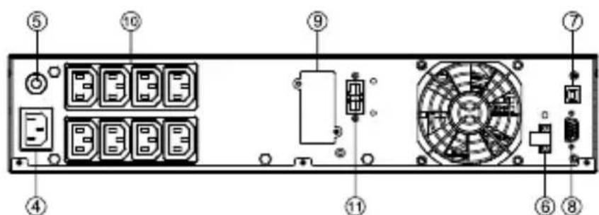
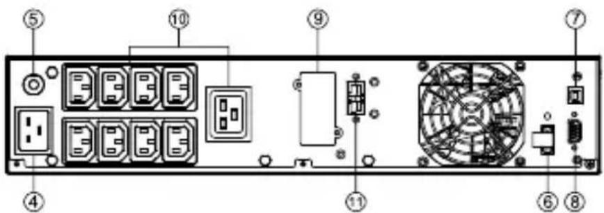
POWER MODULE FRONT/REAR PANEL DESCRIPTION
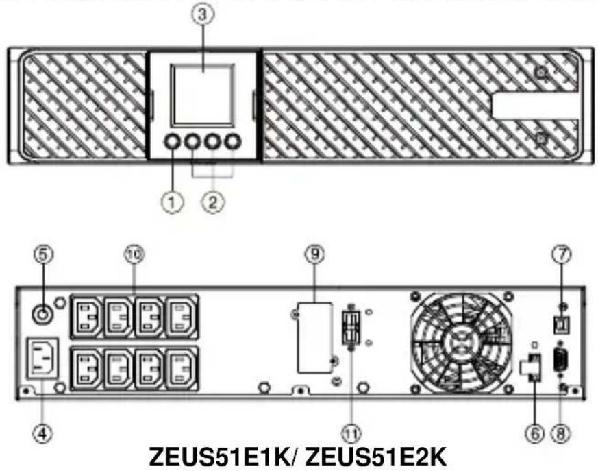
- Power On/Off Button
Master ON/OFF for the UPS.
- Function Buttons
Scroll up, scroll down, select and cancel LCD menu.
- Multifunction LCD Readout
Indicate status information, settings and events.
- AC Input Inlet
Connect the AC Power cord to a properly wired and grounded outlet.
- Input Circuit Breaker
Provide input overload and fault protection.
- EPO (Emergency Power Off) Connector
Enable Power-Off in emergency from a remote location.
7. USB port
This is a connectivity port which allows communication and control between the UPS and the connected computer. It is recommended to install the Power master software on the PC/Server connected with the USB cord.
8. Serial Port
Serial port provides communication between the UPS and the computer. The UPS can control the computer's shutdown during a power outage through the connection while the computer can monitor the UPS and alter its various programmable parameters.
9. SNMP/HTTP Network slot
Slot to install the optional SNMP card for remote network control and monitoring.
10. Battery Backup & Surge Protected Outlets
Provide battery backup and surge protection. They ensure power is provided to connected equipment over a period of time during a power failure.
11. Extended Runtime Battery Module Connector
Connect to additional external battery modules.
HARDWARE INSTALLATION
These versatile UPS systems can be mounted in a rackmount or vertical tower orientation. This versatility is especially important to growing organizations with changing needs that value having the option to position a UPS on a floor or in a rackmount system. Please follow the instructions below for the respective mounting methods.
SAFETY PRECAUTIONS
CAUTION! To prevent the risk of fire or electric shock, only use the supplied hardware to attach the mounting brackets.
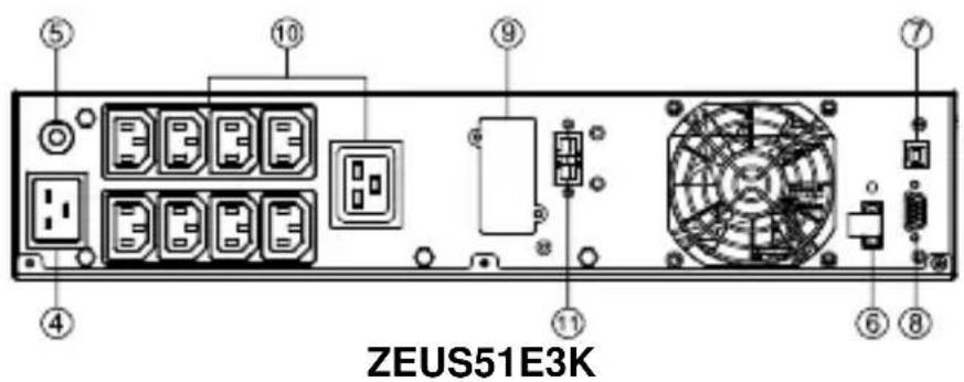
RACKMOUNT INSTALLATION
Step 1: Rackmount ears installation
Attach the two rackmount ears to the UPS using the provided screws M4X8L*8pcs.
natural_image
Technical line drawing of a computer chassis with directional arrows indicating movement or force (no text or symbols present)Step 2: Rackmount rails Installation(optional)
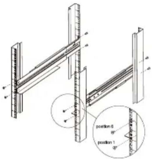
1) The rails adjust to mount in 48-cm (19-inch) panel racks from 52 to 91.5cm (20.5 to 36 inches) deep. Select the proper holes in the rack for positioning the UPS in the rack. The UPS takes up position 1 through position 6.
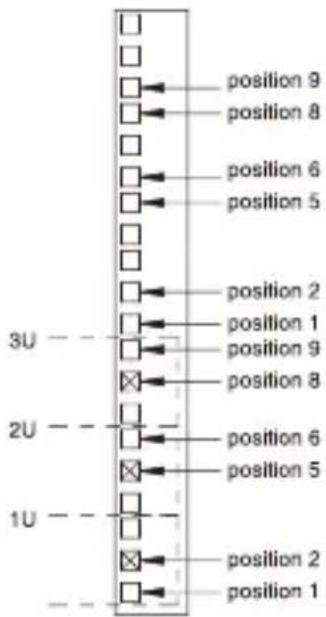
2) Attach the rackmount rail to your rack with two M5X12L screws and two plastic washers at the front of the rack. (Located in position 1 & position 6) Do not tighten the screws. Adjust the rail size on the rail assembly of your rack. Secure the rail to the rear of the rack with two M5X12L screws and two plastic washers. Tighten all screws at the front and rear of the rail. Once completed, perform the same steps for assembling the other rackmount trail.
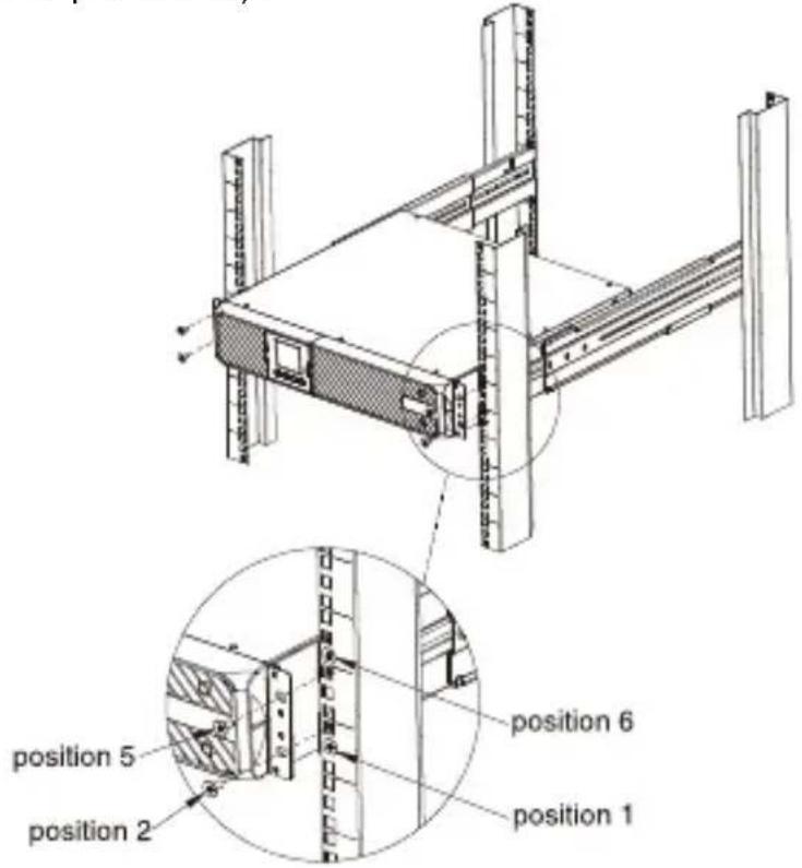
Step 3: Install the UPS on the rack (optional)
Place the UPS on a flat stable surface with the front of the unit facing toward you. Secure the UPS to your rack with four M5X12L screws at the front of the rack. (Located in position 2 & position 5).
VERTICAL/TOWER INSTALLATION
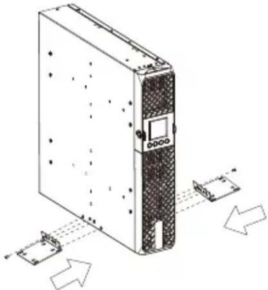
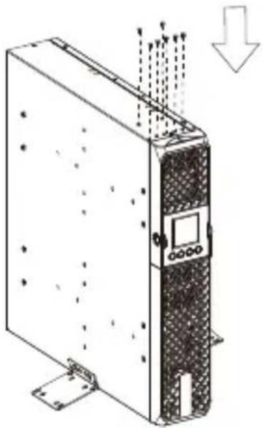
Step 1: Attach the base stands
Tighten the screws (M4X8L*8pcs) of the base stands (rackmount ears) onto the bottom of the UPS.
natural_image
Diagram of an industrial server unit with multiple ports and signal flow arrows (no text or labels)Step 2: Attach dust covers
Insert dust cover into the rackmount ear screw holes that are not being used.
natural_image
Technical line drawing of a server rack with ventilation ducts and mounting base (no text or symbols)SOFTWARE INSTALLATION
Power Master+ management software provides a user-friendly interface for your power systems. The graphic user-interface is intuitive and displays essential power information at a glance. Please follow procedure below to install the software.
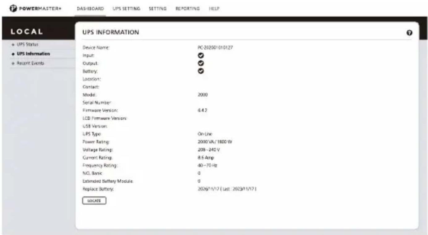
Installation procedure:
- Download Power Master+ from the website: https://www.powermonitor.software/
- Double-click the file and follow the installation steps. When your computer restarts, the Power Master+ software will appear as a blue icon located in the system tray.
DEUTSCH
ZEUS51E1K/ ZEUS51E2K

ZEUS51E3K
1. Ein-/Aus-Taste
6. EPO (Emergency Power Off)-Anschluss
natural_image
Technical line drawing of a computer rack with ventilation ducts and directional arrows indicating movement (no text or symbols)Schritt 2: Installation der Rackmontageschienen (optional)
natural_image
Technical line drawing of a server rack with directional arrows indicating movement or data flow (no text or symbols present)natural_image
Technical line drawing of a server rack unit with mounting base and control panel (no text or symbols)SOFTWAREINSTALLATION
ZEUS51E1K/ ZEUS51E2K

ZEUS51E3K
natural_image
Technical line drawing of a computer rack with directional arrows indicating movement (no text or symbols)natural_image
Diagram of a server rack with multiple ports and directional arrows indicating data flow (no text or labels)natural_image
Technical line drawing of a server rack with mounting bracket and ventilation duct (no text or symbols)INSTALLATION DU LOGICIEL
DESEMPAQUETADO
ZEUS51E1K/ ZEUS51E2K

ZEUS51E3K
natural_image
Technical line drawing of a server rack with directional arrows indicating movement (no text or symbols)natural_image
Diagram of a server rack with multiple ports and directional arrows indicating data flow (no text or labels)natural_image
Technical line drawing of a server rack with mounting base and ventilation duct (no text or symbols)INSTALACIÓ N DEL SOFTWARE
ZEUS51E1K/ ZEUS51E2K

ZEUS51E3K
- Connettore EPO (Emergency Power Off)
natural_image
Technical line drawing of a server rack with ventilation ducts and directional arrows indicating movement (no text or symbols)natural_image
Diagram of a server rack with multiple ports and directional arrows indicating movement or data flow (no text or symbols present)natural_image
Technical line drawing of a server rack with mounting base and ventilation duct (no text or symbols)DESEMBALAGEM
ZEUS51E1K/ ZEUS51E2K
ZEUS51E3K
natural_image
Technical line drawing of a computer chassis with directional arrows indicating movement or force (no text or symbols present)Passo 3: Instalar o UPS no rack (opcional)
Passo 1: Anexar as bases
natural_image
Diagram of a server rack with multiple ports and directional arrows indicating data flow (no text or labels)Passo 2: Anexar as tampas protetoras
natural_image
Technical line drawing of a server rack with mounting bracket and load arrow (no text or symbols)ROZPAKOWYWANIE
ZEUS51E3K
INSTALACJA W SZAFIE RACKOWEJ
natural_image
Technical line drawing of a computer drive chassis with mounting bracket and side-mounted ports (no text or symbols)INSTALACJA W PIONOWYM/UŻYTKU WIEŻOWYM
natural_image
Diagram of a server rack with multiple ports and directional arrows indicating data flow (no text or labels)natural_image
Technical line drawing of a server rack unit with mounting base and ventilation duct (no text or symbols)INSTALACJA OPROGRAMOWANIA
ZEUS51E1K/ ZEUS51E2K

ZEUS51E3K
- Bekapcsológomb
RACKMOUNT TELEPÍ TÉS
natural_image
Technical line drawing of a computer drive chassis with mounting hardware and directional arrows indicating movement (no text or symbols)natural_image
Diagram of a server rack with multiple ports and directional arrows indicating data flow (no text or labels)natural_image
Technical line drawing of a server rack with mounting bracket and load arrow (no text or symbols)SZOFTVER TELEPÍ TÉSE
https://www.powermonitor.software/
- UNPACKING
- USB port
- Serial Port
- SNMP/HTTP Network slot
- Battery Backup & Surge Protected Outlets
- Extended Runtime Battery Module Connector
- HARDWARE INSTALLATION
- SAFETY PRECAUTIONS
- RACKMOUNT INSTALLATION
- Step 1: Rackmount ears installation
- Step 2: Rackmount rails Installation(optional)
- Step 3: Install the UPS on the rack (optional)
- VERTICAL/TOWER INSTALLATION
- Step 1: Attach the base stands
- Step 2: Attach dust covers
- SOFTWARE INSTALLATION
- Installation procedure:
- DEUTSCH
- Ein-/Aus-Taste
- EPO (Emergency Power Off)-Anschluss
- Schritt 2: Installation der Rackmontageschienen (optional)
- SOFTWAREINSTALLATION
- INSTALLATION DU LOGICIEL
- DESEMPAQUETADO
- INSTALACIÓ N DEL SOFTWARE
- DESEMBALAGEM
- Passo 3: Instalar o UPS no rack (opcional)
- Passo 1: Anexar as bases
- Passo 2: Anexar as tampas protetoras
- ROZPAKOWYWANIE
- INSTALACJA W SZAFIE RACKOWEJ
- INSTALACJA W PIONOWYM/UŻYTKU WIEŻOWYM
- INSTALACJA OPROGRAMOWANIA
- RACKMOUNT TELEPÍ TÉS
- SZOFTVER TELEPÍ TÉSE
Brand : Equip
Model : ZEUS51E
Category : Uninterruptible power supply