
HF910P 011 - Vacuum Cleaner CANDY - Free user manual and instructions
Find the device manual for free HF910P 011 CANDY in PDF.


| Product type | Cordless stick vacuum cleaner |
| Brand | Candy |
| Model | HF910P 011 |
| Power supply | Rechargeable lithium-ion battery, 230 V mains charger |
| Charging time | Approximately 3.5 hours |
| Operating modes | Stick, height, handheld vacuum |
| Power settings | MODE button (hard floors/carpets), TURBO button for enhanced suction |
| Indicators | LED display: battery level, mode, error code; brush status indicator |
| Lighting | LED on the main brush |
| Container capacity | Maximum fill line (visual indicator) |
| Filters | Foam pre-motor filter and exhaust filter, washable (24 h drying) |
| Included accessories | Power brush, mini turbo brush, 2-in-1 all-surface/furniture brush, crevice tool, wall mount, additional battery (optional) |
| Brush maintenance | ANTI-TWIST system: integrated comb reduces hair wrap; easy disassembly for cleaning |
| Safety | Household use only; do not vacuum liquids, hot or sharp objects; keep hands and hair away from rotating brushes |
| Error codes | E1 (filter missing), E2 (battery defective), E3 (brush obstruction), E4 (brush cover not closed properly), E5 (general blockage), E6/E8 (technical problem), E7 (charger), E9 (mini turbo brush blockage) |
| Battery warranty | 2 years |
| Spare parts and repairability | Use only Hoover spare parts; repair by an authorized Hoover repairer |
| Disposal | Remove the battery before disposal; recycle according to local regulations |
| Compliance | European directives 2014/35/EU, 2014/30/EU, 2011/65/EU |
Frequently Asked Questions - HF910P 011 CANDY
User questions about HF910P 011 CANDY
0 question about this device. Answer the ones you know or ask your own.
Ask a new question about this device
Download the instructions for your Vacuum Cleaner in PDF format for free! Find your manual HF910P 011 - CANDY and take your electronic device back in hand. On this page are published all the documents necessary for the use of your device. HF910P 011 by CANDY.
USER MANUAL HF910P 011 CANDY


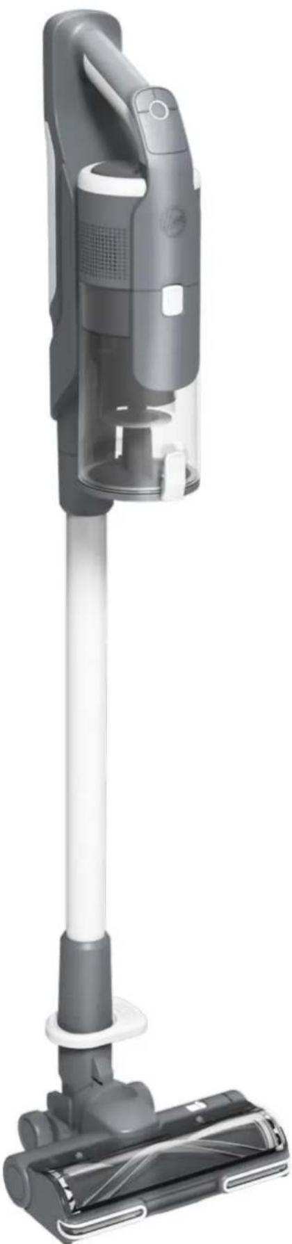
This appliance should only be used for domestic cleaning, as described in this user guide. Please ensure that this guide is fully understood before operating the appliance.
Always switch off and remove the charger from the socket before cleaning the appliance or any maintenance task.
This appliance can be used by children aged from 8 years and above and persons with reduced physical, sensory or mental capabilities or lack of experience and knowledge if they have been given supervision or instruction concerning use of the appliance in a safe way and understand the hazards involved. Children shall not play with the appliance.
Cleaning and user maintenance shall not be made by children without supervision.
If the power cord is damaged stop using the appliance immediately. To avoid a safety hazard, an authorised Hoover service engineer must replace the power cord.
Use only the original charger supplied with the appliance.
Check that your supply voltage is the same as that stated on the charger. This appliance is supplied with a double insulated battery charger which is only suitable for insertion in a 230V (UK 240V) socket outlet.
Plug the charger in to suitable socket outlet and connect the charger jack plug to the appliance.
When charging the appliance, the power switch lever must be in the off position.
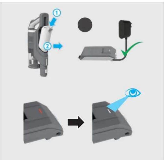
The battery pack LED light will illuminate Red during charging and will turn white when fully charged.
Re-connect the appliance to the charger after use to recharge the battery.
Never charge the batteries in temperatures above 37°C or below 0°C. It is normal for the charger to become warm to the touch when charging.
Unplug the charger in the event of prolonged absence (holidays, etc.). Recharge appliance again before use as batteries may self discharge over increased periods of storage.
Use only attachments, consumables or spares recommended or supplied by Hoover.
Static electricity: some carpets can cause a small build up of static electricity. Any static discharge is not hazardous to health.
Keep hands, feet, loose clothing and hair away from rotating brushes.
Do not unplug the charger by pulling on the power cord.
Do not use your appliance out of doors or on any wet surface or for wet pick up. Do not pick up hard or sharp objects, matches, hot ashes, cigarette ends or other similar items.
Do not spray with or pick up flammable liquids, cleaning fluids, aerosols or their vapours.
Do not run over the power cord when using your appliance or remove the plug by pulling on the power cord. Do not continue to use your appliance or charger if it appears faulty.
Do not use the appliance to clean animals or people. Do not replace the batteries with non-rechargeable batteries.
Hoover service: To ensure the continued safe and efficient operation of this appliance we recommend that any servicing or repairs are only carried out by an authorised Hoover service engineer.
End of product Life disposal
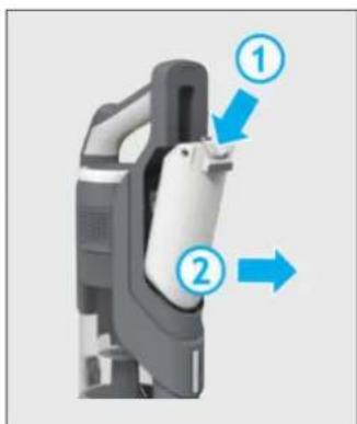
If the appliance is to be disposed of the batteries must be removed. The appliance must be disconnected from the supply mains when removing the battery. Dispose of the batteries safely. Run the appliance until it stops because the batteries are fully discharged. Used batteries should be taken to a recycling station and not disposed of with household waste. To remove the batteries, please contact the Hoover Customer Centre or proceed according to the following instructions.
IMPORTANT: Always fully discharge the batteries before removal.
Run the cleaner until the batteries are completely empty. Remove the charger jack plug from the appliance.
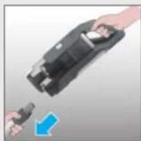
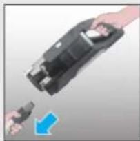
Press the battery pack release buttons and slide to remove.
Note: Should you experience any difficulty in dismantling the unit or for more detailed information on treatment, recovery and recycling of this appliance, please contact your local city office or your household waste disposal service.
The Environment
The symbol on this appliance indicates that this appliance may not be treated as household waste. Instead it must be handed over to the applicable collection point for the recycling of electrical and electronic equipment. Disposal must be carried out in accordance with local environmental regulations for waste disposal. For more detailed information about treatment, recovery and recycling of this appliance, please contact your local city office, your household and waste disposal service or the shop where you purchased the appliance.
GB

This appliance complies with the European Directives 2014/35/EU, 2014/30/EU and 2011/65/EU.
CANDY HOOVER GROUP S.r.l. Via Privata Eden Fumagalli, 20861 Brugherio (MB) Italy
2. IMPORTANT INFORMATION
Hoover Spares and Consumables
Always replace parts with genuine Hoover spares. These are available from your local Hoover dealer or direct from Hoover. When ordering parts always quote your model number.
Quality
Hoover's factories have been independently assessed for quality. Our products are made using a quality system which meets the requirements of ISO 9001.
Your Guarantee
The guarantee conditions for this appliance are as defined by our representative in the country in which it is sold. Details regarding these conditions can be obtained from the dealer from whom the appliance was purchased. The bill of sale or receipt must be produced when making any claim under the terms of this guarantee.
2 Year battery warranty
IMPORTANT: The battery in this cleaner is guaranteed for 2 years from the date of purchase. After 2 years the customer is liable for the cost of a new battery.
Subject to change without notice.
MAIN COMPONENTS:
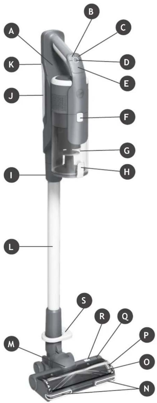
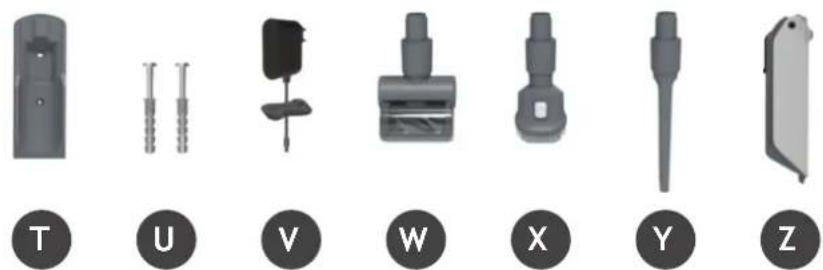
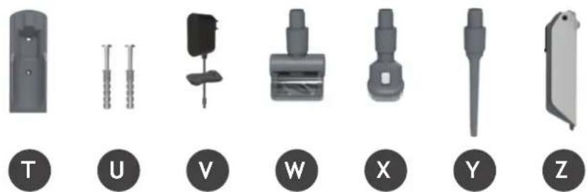
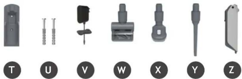
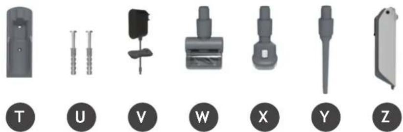
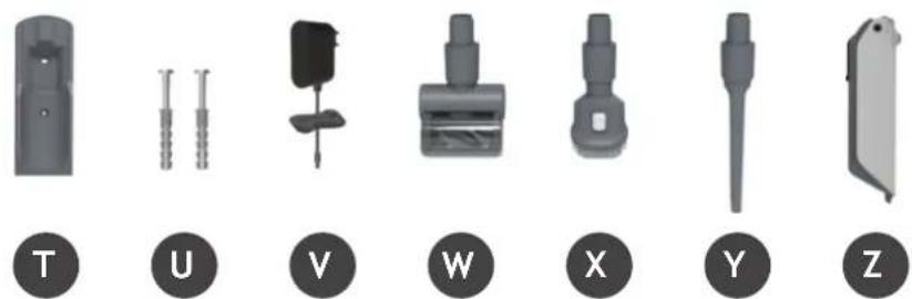
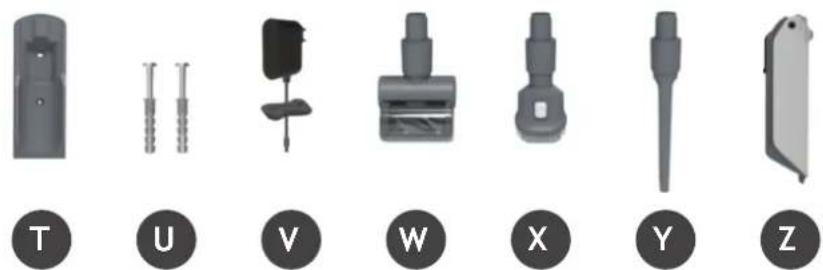
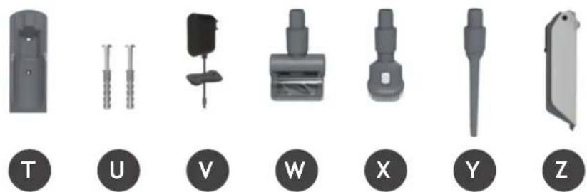
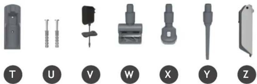
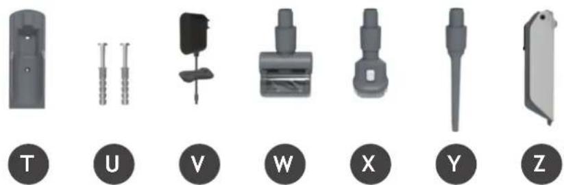
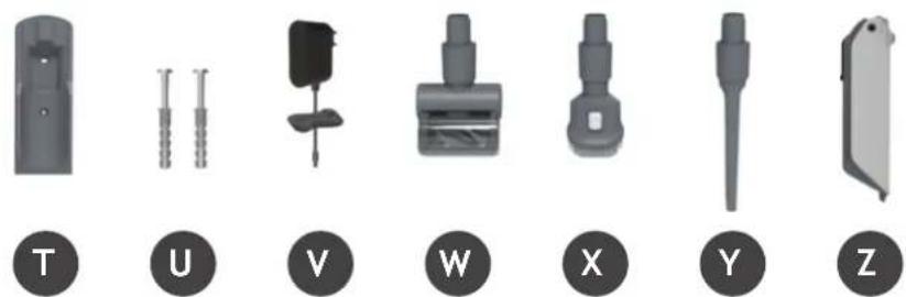
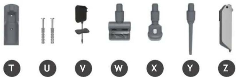
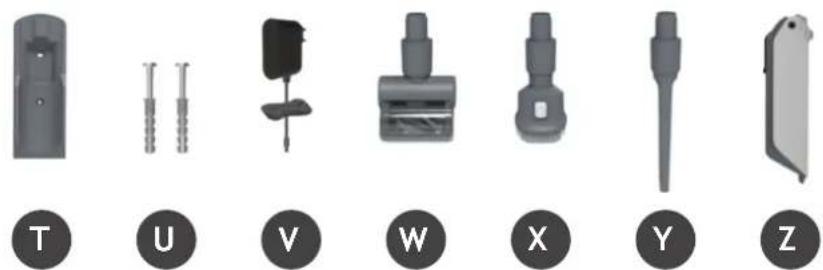
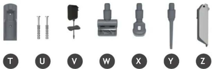
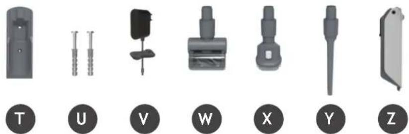
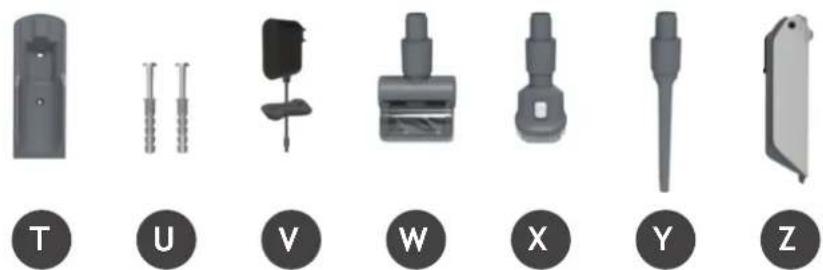
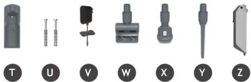
A. Handheld unit B. Mode button C. Turbo button D. On/Off Power button E. LED Display F. Dust bin release button G. Dust bin H. Dust bin flap release button I. Handheld release button J. Battery K. Battery release button L. Tube M. Floor nozzle N. Nozzle LED lights O. Nozzle window P. Brushbar release latch Q. Brushbar status light R. Nozzle window release latch S. Nozzle release pedal T. Wall mount U. Wall mount screws & fixings V. Charger W. Mini-turbo nozzle* X. 2-in-1 Dusting brush/Furniture tool Y. Crevice tool Z. Extra battery*
4. PREPARING YOUR CLEANER
Remove all product parts from the packaging and assemble your cleaner.
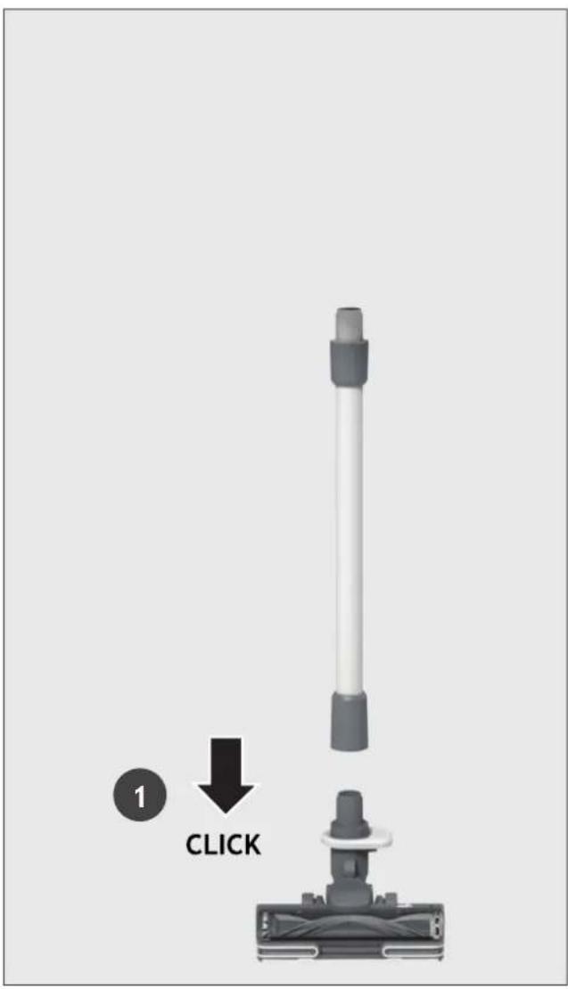
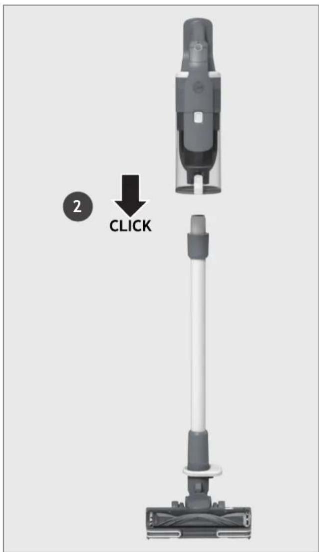
STEP 1: Fit the tube into the floor nozzle.
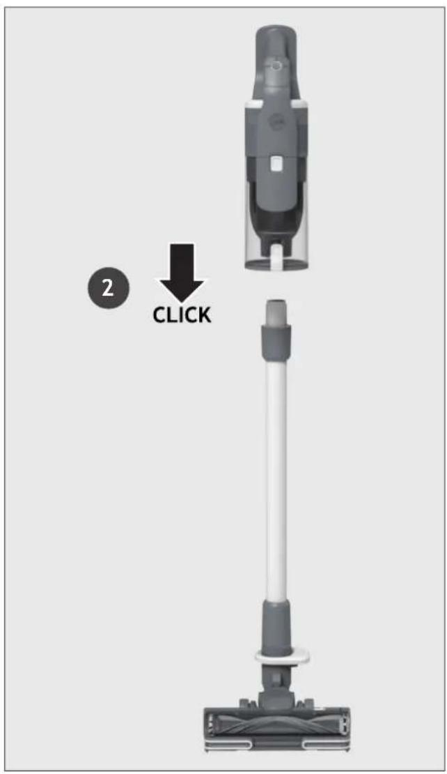
STEP 2: Fit the handheld unit onto the tube.
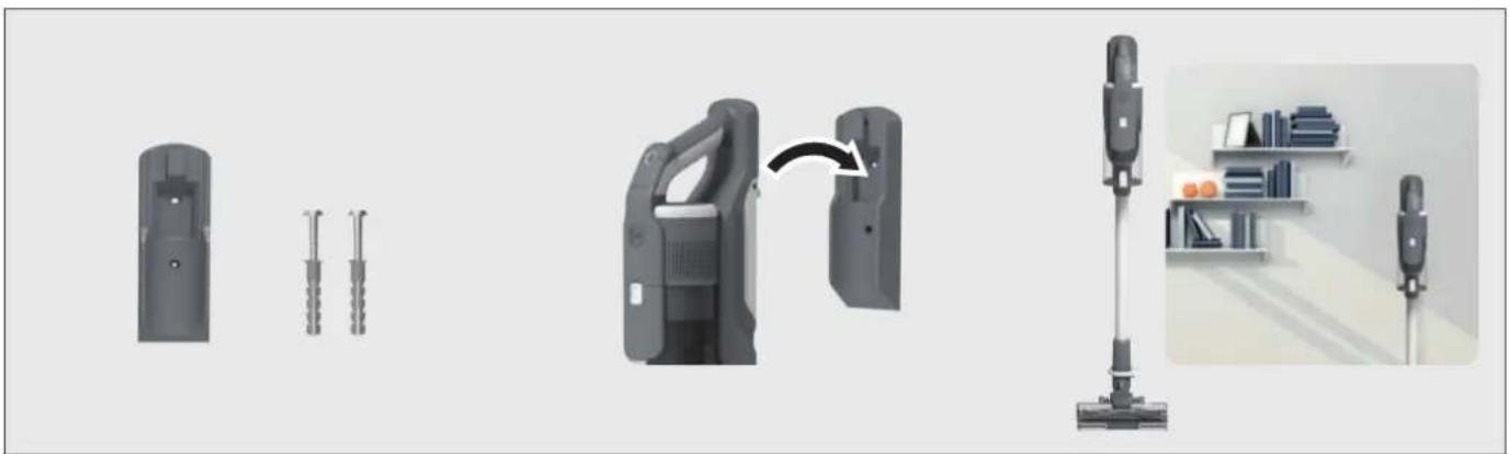
We provide a wall mount for optional storage.
If you wish to use it, fix the wall mount to a suitable wall using the screws and fixings provided.
5. CHARGING THE BATTERY
The battery in your product does not come fully charged.
Before first use, please charge it completely: this should take around 3.5 hours.
For your convenience, the battery can be charged in 3 different conditions.
- With the product fully assembled in stick mode or located in the wall mount, the battery status will be indicated on the LED display.
- With the product In the handheld mode, the battery status will be indicated on the LED display.
- With the battery removed from the product, the battery pack led will illuminate RED when charging and turn WHITE when fully charged.
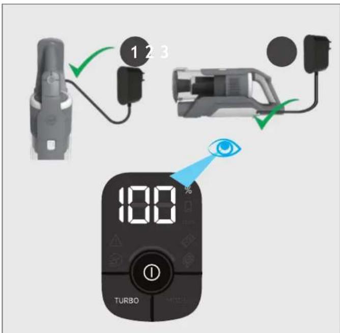
When using your product, the real time charge level of your battery is indicated on the LED display located on the handheld.
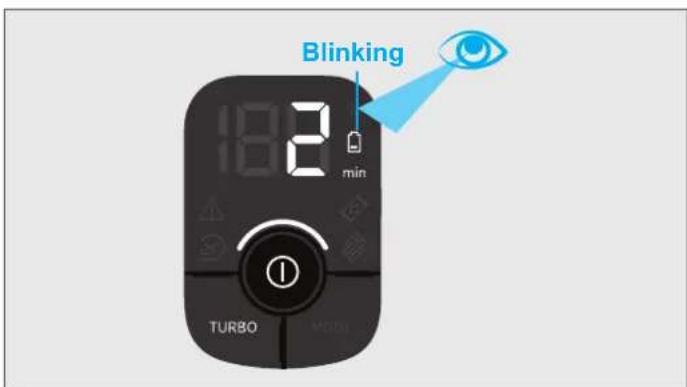
When the remaining run time is reduced to 2 mins, the LED display icons will begin to blink.
It is recommended that you switch off your product and recharge the battery.
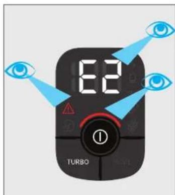
In the unlikely event that your LED display shows an error code E2, this indicates a fault with your battery.
It is recommended that you immediately switch off your product, remove the battery, and contact your local Hoover service centre.
6. USING YOUR CLEANER
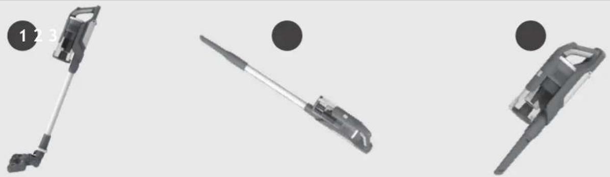
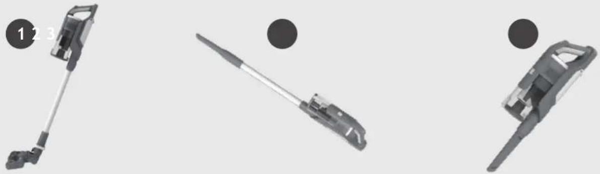
There are 3 different working modes for your cleaner:
- Stick mode.
- Above Floor mode.
- Handheld mode.
6.1 STICK MODE
To use your product in Stick mode:
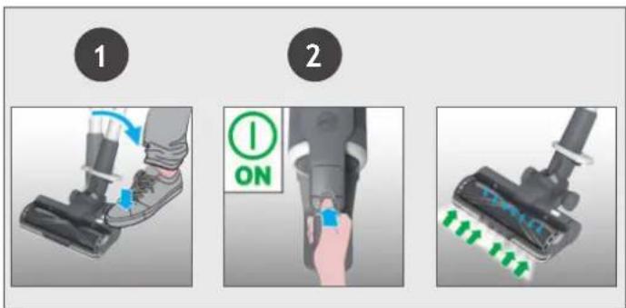
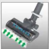
- Place your foot on the nozzle and pull back to recline the tube.
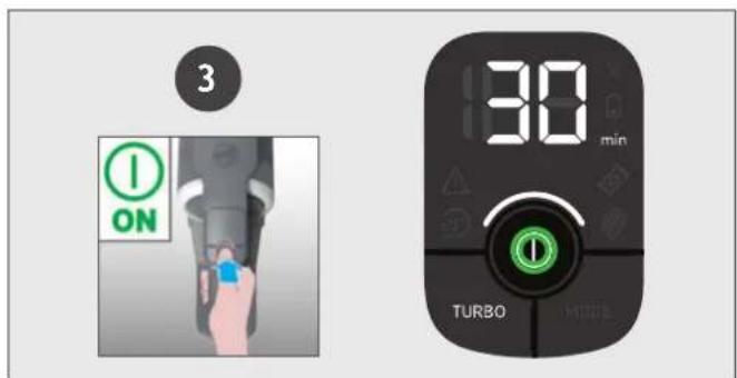
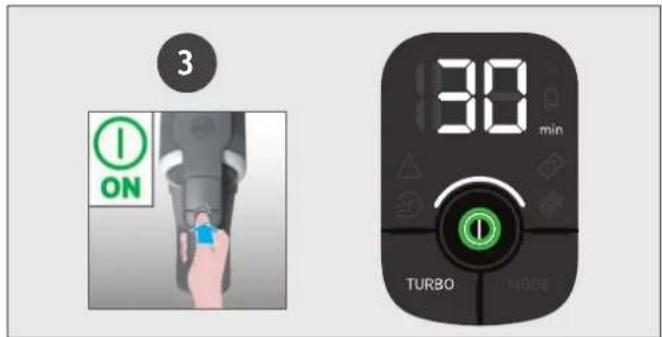
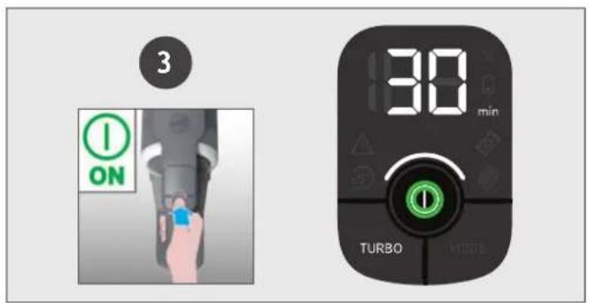
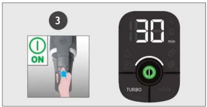
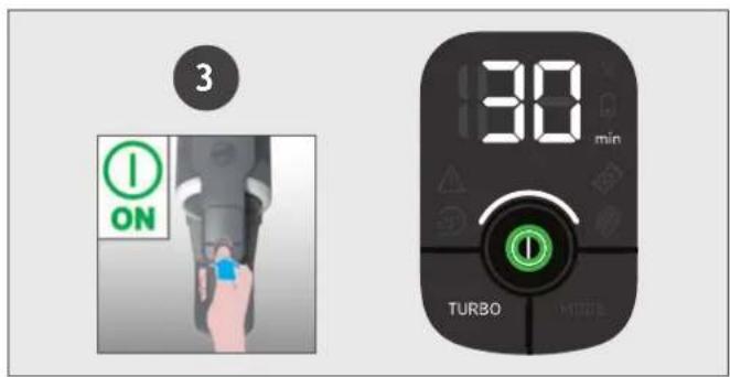
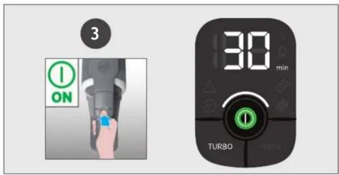
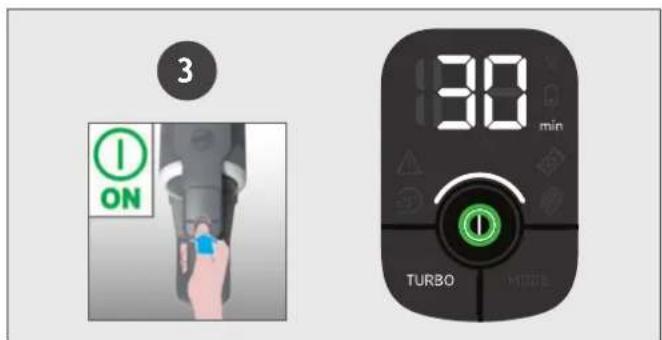
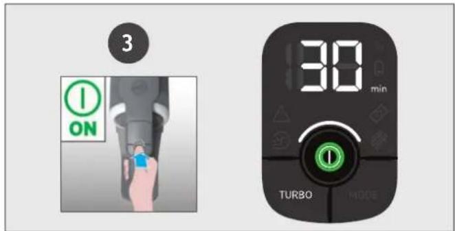
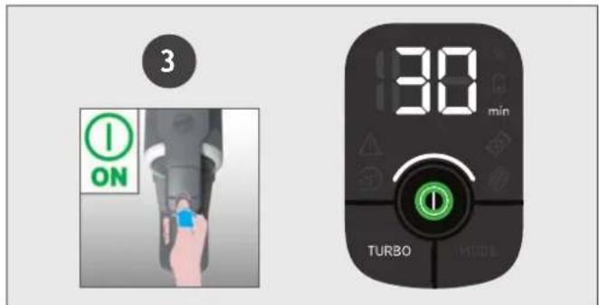
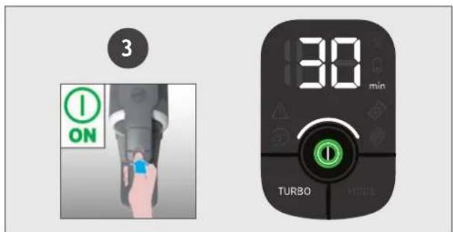
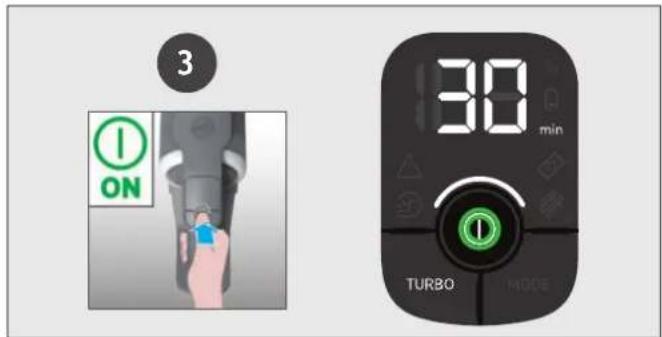
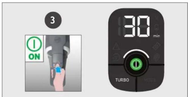
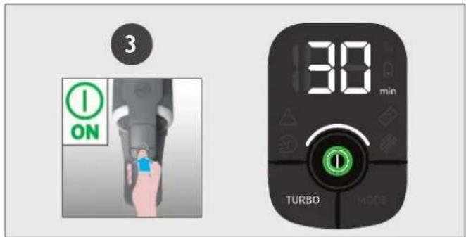
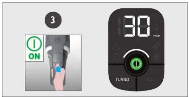
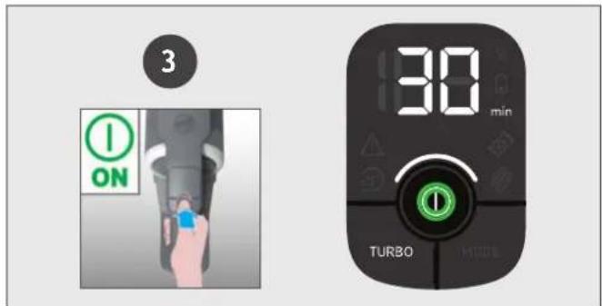
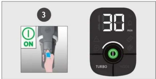
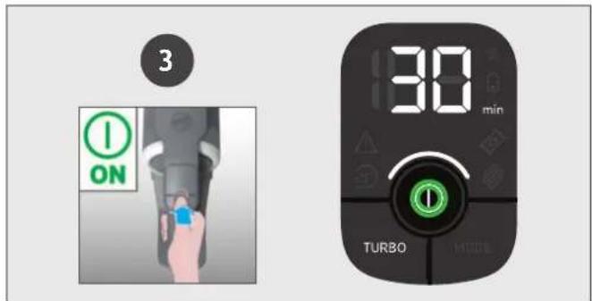
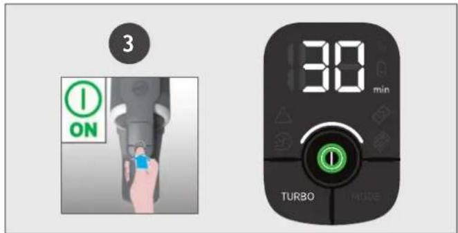
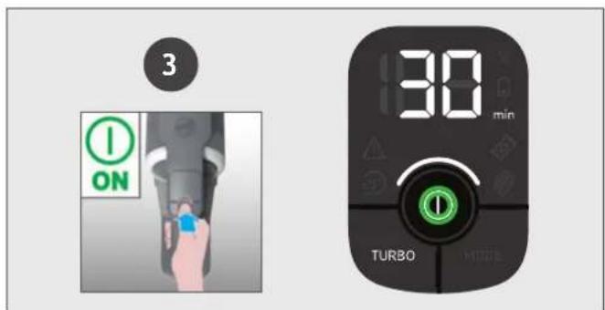
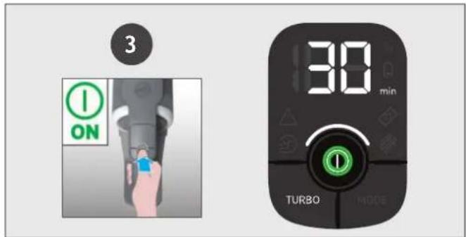
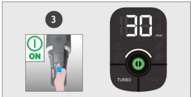
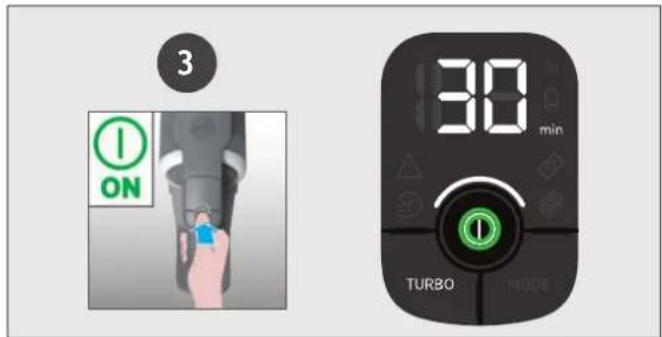
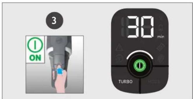
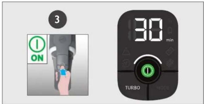
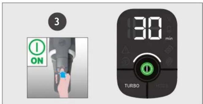
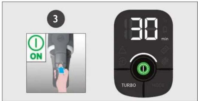
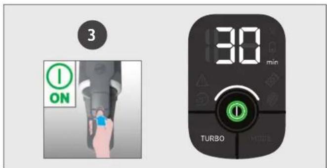
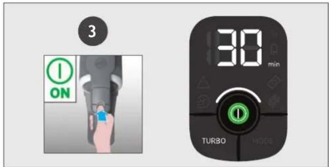
- Press the On/Off power button to begin cleaning. NOTE: The nozzle LED lights are always on and the brushbar is always rotating.
Controls settings:
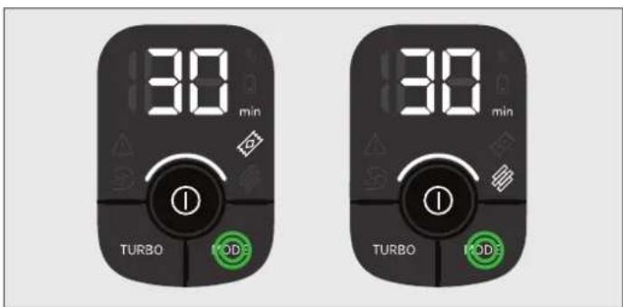
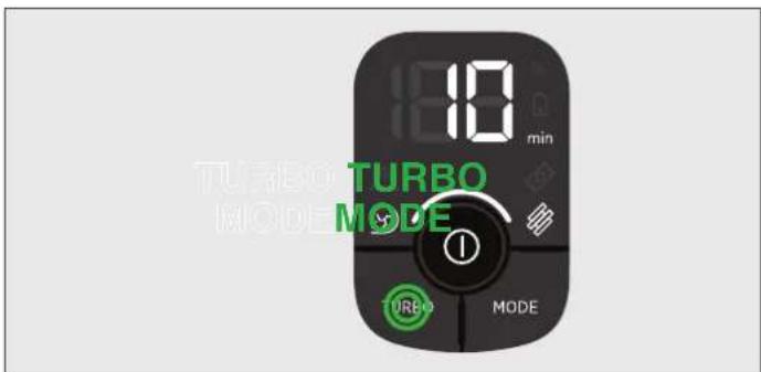
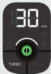
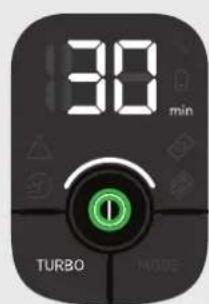
Press the MODE button to select your desired floor surface, the LED display icon of HARD FLOOR or CARPET will illuminate to confirm your setting.
If you require a deeper clean when using your product in Stick mode, press the turbo button to increase the power.
The turbo icon will illuminate on the LED display to confirm your selection.
Please note this will reduce your battery runtime.
To return to standard mode, press the turbo button; the icon on the display will turn off.
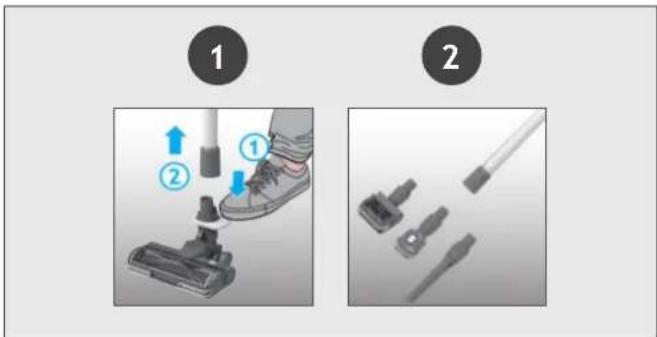
To use your product in Above Floor mode:
- Remove the tube from the nozzle by pressing the nozzle release pedal and pulling the tube from the floor nozzle.
- Fit your desired accessory to the end of the tube. All of your available accessories will fit onto the end of the tube.
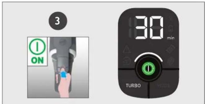
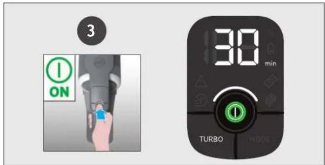
- Press the On/Off power button to begin cleaning.
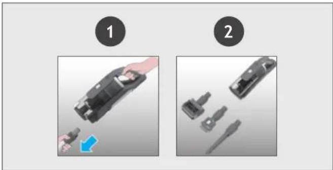
To use your product in handheld mode:
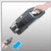
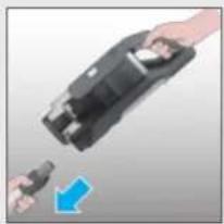
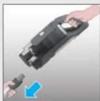
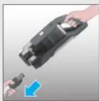
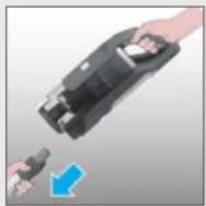
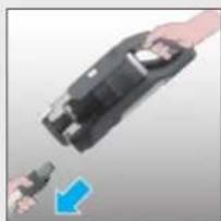
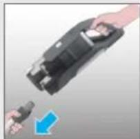
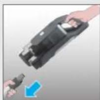
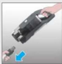
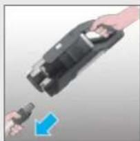
- Remove the Handheld unit from the tube by pressing the handheld release button and pulling apart.
- Fit your desired accessory to the end of the handheld unit. The floor nozzle and all of your available accessories will fit onto the end of the handheld unit.
- Press the On/Off power button to begin cleaning.
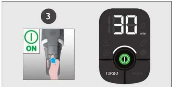
Control settings:
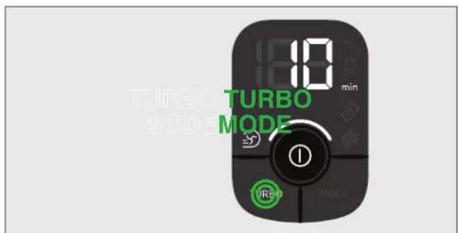
If you require a deeper clean when using your product in Above floor or Handheld mode, press the turbo button to increase the power.
The turbo icon will illuminate on the LED display to confirm your selection.
Please note this will reduce your battery runtime.
To return to standard mode, press the turbo button; the icon on the LED display will turn off.
7. CLEANER MAINTENANCE 7.1 EMPTYING THE DUST BIN
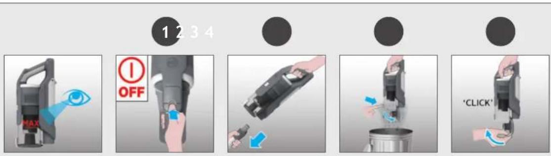
When the debris in your dust bin reaches the max fill line, empty your bin.
- Switch off your product.
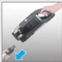
- Press the handheld release button and remove the handheld unit from the tube.
- Hold the handheld unit over a bin and press the bin flap release button to open the flap and release the debris into the trash.
- Close the bin flap.
7. CLEANER MAINTENANCE 7.2 FILTERS
It is recommended to wash your filters after every 5 bin empties.
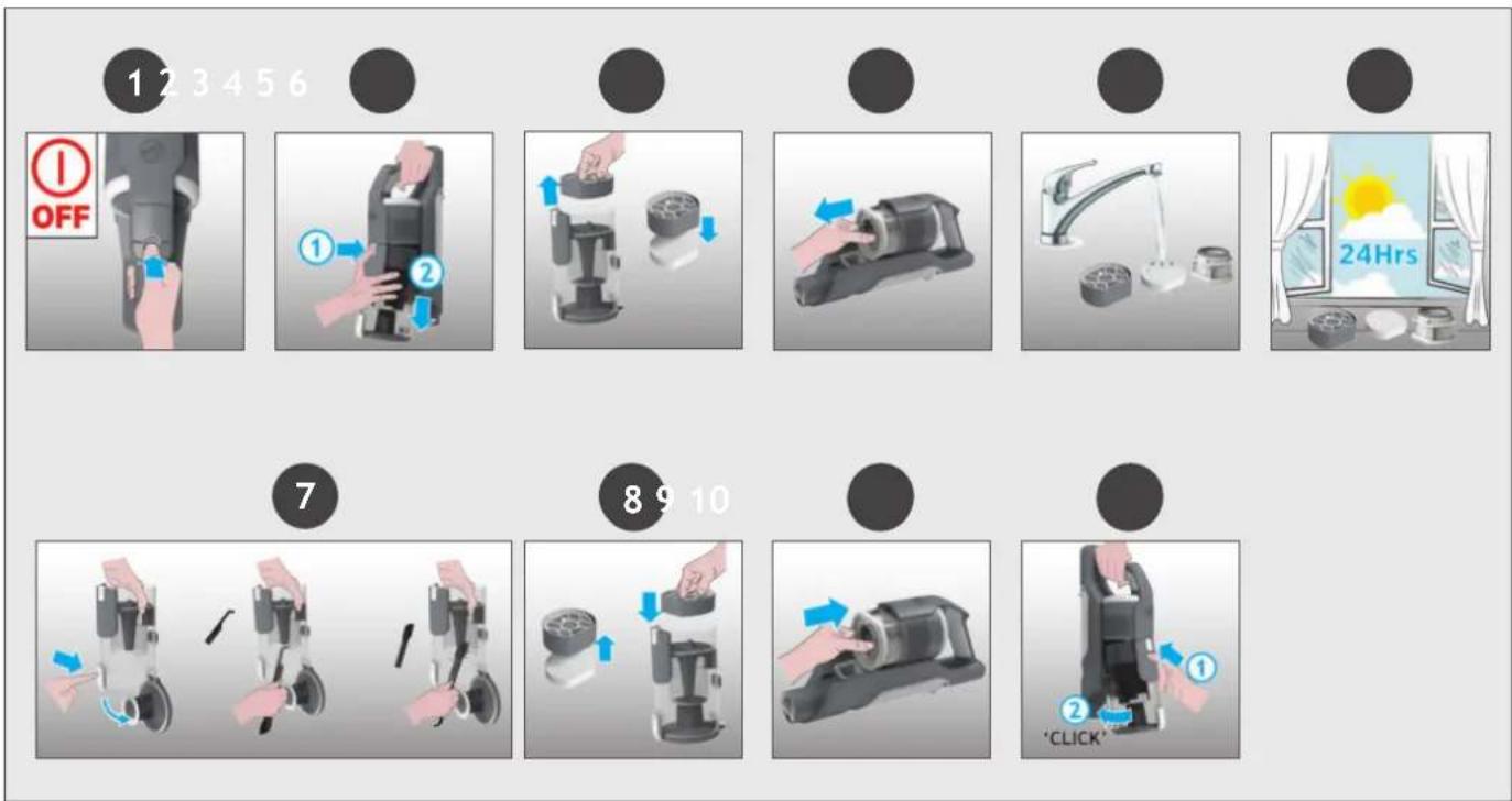
- Ensure your product is switched off.
- Press the bin release button and remove the bin assembly from the handheld unit.
- Remove the pre-motor filters from the bin and separate the foam filter.
- Remove the exhaust filter from the handheld unit.
- Remove any excess debris from the filters and wash all 3 filters using lukewarm water.
- Leave to dry for 24hrs before refitting to your product.
- Use the cleaning tool provided to remove any excess debris from inside the dust bin.
- Re-fit the foam filter to the pre-motor filter and re-fit into the bin.
- Re-fit the exhaust filter to the handheld unit.
- Re-fit the bin to the handheld unit.
7. CLEANER MAINTENANCE
7.3 FLOOR NOZZLE
Thanks to ANTI-TWIST, your Hoover vacuum features an integrated comb which radically reduces hair wrapping around the brushbar. However, if your cleaner is not picking up efficiently your brushbar may need to be cleaned.
- Switch off your product.
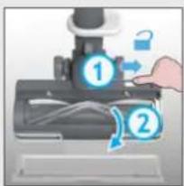
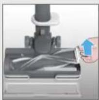
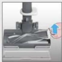
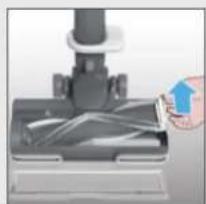
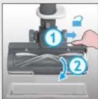
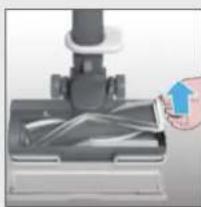
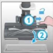
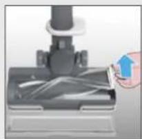
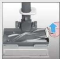
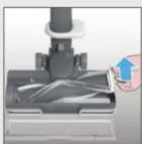
- Unlock the nozzle window sliding the nozzle window release latch and remove.
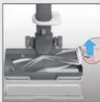
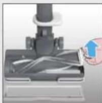
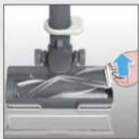
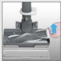
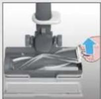
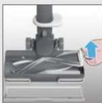
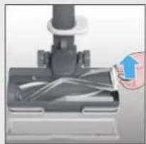
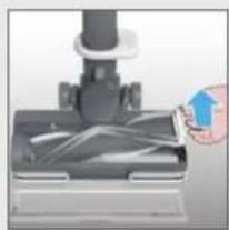
- Using the brushbar release latch, remove the brushbar from the nozzle.
- Remove any excess debris from the brushbar.
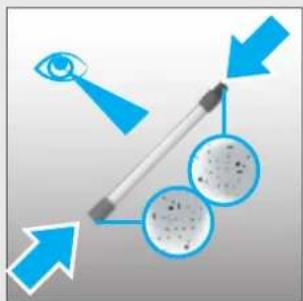
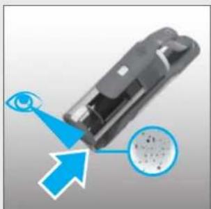
- Check for and remove any large debris from inside the nozzle.
- Carefully check for and remove any tangled debris from the comb.
- Refit the brushbar to the nozzle ensuring the latch is fully in place.
- Refit the nozzle window by locating at the front of the nozzle and closing firmly into location.
IMPORTANT: Ensure the window is fully closed. If the nozzle window is not correctly reassembled, the nozzle LED lights will flash, the brushbar status light will turn red and error E03 will appear on the user interface.
7. CLEANER MAINTENANCE 7.4 MINI-TURBO NOZZLE*
- Switch off your product.
- Remove the mini-turbo nozzle from your product and turn over.
- Using a coin, open the brushbar release lock and remove the brush bar.
- Using scissors, remove any tangled fibres or debris from the brushbar.
- Look inside the nozzle and remove any debris.
- Refit the brushbar into the nozzle and using a coin, lock into position.
![graph LR A["Brush"] --> B["Presser"] B --> C["Close-up"] C --> D["Close-up"] D --> E["Arrow pointing to brush tip"] E --> F["Arrow pointing to brush tip"] F --> G["Arrow pointing to brush tip"] G --> H["Arrow pointing to brush tip"]](/content/2026/04/705857/images/d4393c1f3509e5f8f932b2627b044f5a131604b2bfd3de6310805c8318b1496a.jpg)
*Dependant on your model.
7. CLEANER MAINTENANCE
7.5 BLOCKAGES
GB
If your product is still working but has low or no suction, you may have a blockage.
Carry out all maintenance instructions included in sections, 7.1, 7.2 & 7.3.
The following additional areas of your product should also be checked for any debris or blockages:
- Switch off your product.
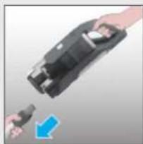
- Separate the Floor nozzle, tube and handheld unit as per previous instructions.
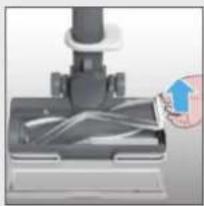
- Remove the nozzle window and brushbar from the nozzle as per previous instructions.
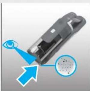
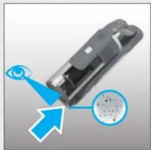
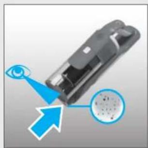
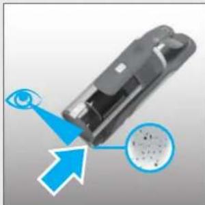
- Position the nozzle neck vertically and visually check for any debris or obstructions and clear.
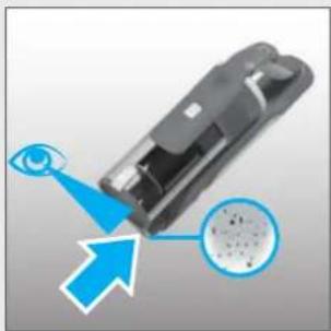
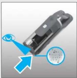
- Visually check the handheld inlet connection area for any debris or obstructions and clear.
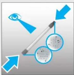
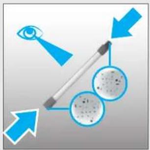
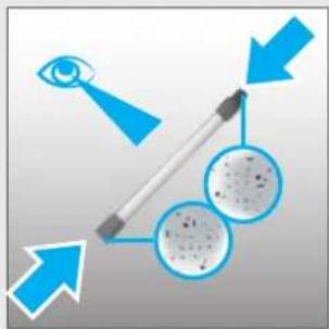
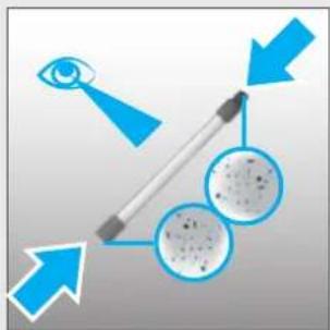
- Visually check both ends of the tube and remove any debris or obstructions.
Re-assemble your product.
1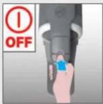
2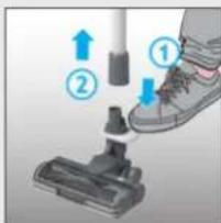
3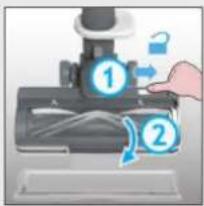
456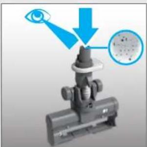
●
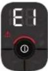
The following is a list of error codes and solutions that your product will identify and indicate on your LED display should your product encounter problems:
| ERROR CODE | FAULT & SOLUTION | |
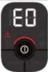 | The pre motor filter is missing!1. Press bin release button to remove the bin.2. Reassemble the pre motor filter in the correct position.3. Reassemble the bin. | 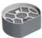 |
 | Check if there is any obstruction in the nozzle.Go to section 7.3 and carry out ALL maintenance requirements. | 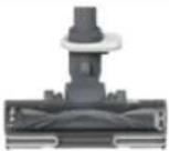 |
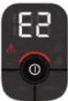 | There is a technical issue in the battery pack.Remove the battery from your product and contact your local Hoover service centre. |  |
 | Check if the window nozzle is correctly assembled in the nozzle.1. Make sure the window is in place correctly.2. Press the window down gently to click it in securely. | 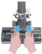 |
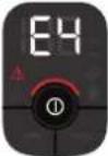 | There is a technical issue in the main nozzle.Switch off your product and wait for 20mins.If the product still does not work, Contact your local Hoover service centre. | 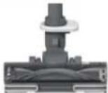 |
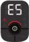 | E5 indicates there is a blockage in your product.Go to section 7 and carry out ALL maintenance requirements, Empty the bin, clean the filters, clean the nozzle & brushbar and check for blockages. |  |
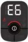 | There is a technical issue in the main vacuum.Stop using your product.Contact your local Hoover service centre. |  |
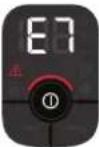 | There is a technical issue in the charger.Please ensure you are using a genuine HOOVER charger.If the problem persists, stop using your product and contact your local Hoover service centre. |  |
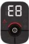 | There is a technical issue in the main vacuum.Switch off your product and wait for 20mins.If the problem persists, stop using your product and contact your local Hoover service centre. |  |
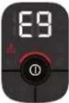 | E9 indicates there is a blockage in the mini turbo nozzle.Go to section 7.4 and perform the indicated maintenance task. | 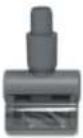 |
1. SAFETY INSTRUCTIONS FOR USE
4. PREPARING THE DEVICE
6. USING THE DEVICE
6.1 SWEEP MODE
6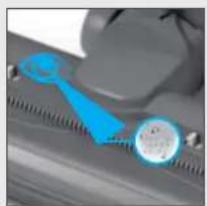
7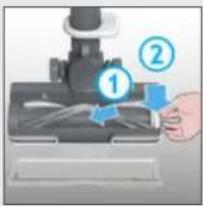
8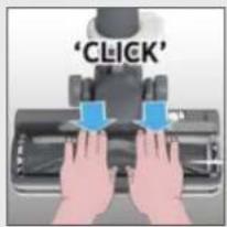
7. MAINTENANCE OF THE VACUUM CLEANER
7.4 MINI TURBO BRUSH*
7. MAINTENANCE OF THE VACUUM CLEANER
7.5 BLOCKAGES
3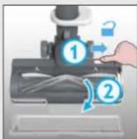


6. USE OF THE DEVICE
6.1 STANDARD MODE
Settings:
●
4. PREPARATION OF THE DEVICE
6. USE OF THE DEVICE
6.1 STANDARD MODE
●
4. ASSEMBLING YOUR VACUUM CLEANER
5. CHARGING THE BATTERY
6. USING YOUR VACUUM CLEANER
6.1 STICK VACUUM MODE
Control settings:
3
456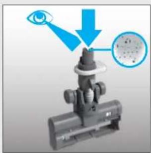
4. PREPARING YOUR VACUUM CLEANER
6. USING YOUR DEVICE
6.1 VERTICAL MODE
2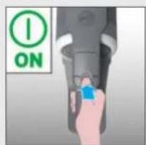
3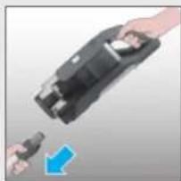
456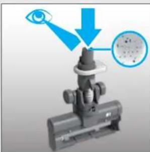
6. USING THE APPLIANCE
6.1 STANDARD MODE
7. APPLIANCE MAINTENANCE
7.5 OBSTRUCTIONS
EN
3
456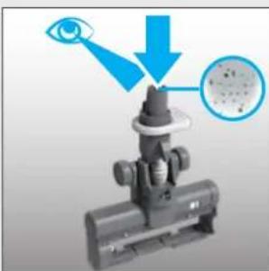
4. HOW TO PREPARE THE VACUUM CLEANER
5. CHARGING THE BATTERY
6. USING THE VACUUM CLEANER
6.1 STICK MODE
To use your product in stick mode:
Operating options:
7.1 EMPTYING THE DUST CONTAINER
3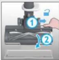
456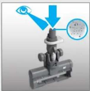

4. PREPARING THE VACUUM CLEANER
5. CHARGE THE BATTERY
6. USING THE APPLIANCE
6.1 STICK MODE

7.1 EMPTYING THE DUST CONTAINER
3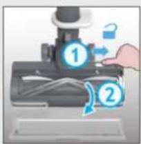
456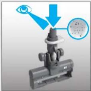
●
●
4. PREPARING YOUR VACUUM CLEANER
5. CHARGING THE BATTERY
6. USE
6.1 STICK MODE
3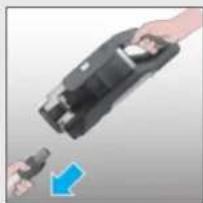

4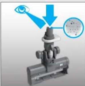
●
4. ASSEMBLING THE DEVICE
5. CHARGING THE BATTERY
6. USING THE DEVICE
6.1 STICK VACUUM MODE
2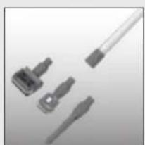
3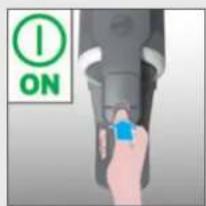
2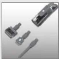
3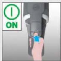
Control settings:
7. MAINTENANCE OF THE DEVICE
7.5 CLOGGING
FI
3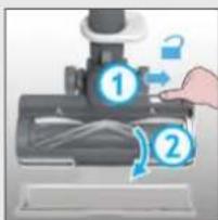
456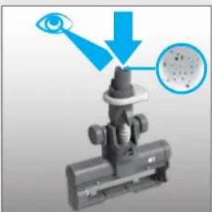
●
6. INSTRUCTIONS FOR USE
6.1 CORRECT USE
Control settings:
3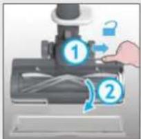
456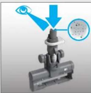
5. BATTERY CHARGING
6.1 HANDHELD MODE
4. PREPARING THE VACUUM CLEANER
5. CHARGING THE BATTERY
6. USING THE VACUUM CLEANER
6.1 CORDLESS MODE
7. MAINTENANCE OF THE DEVICE
7.5 BLOCKAGES
3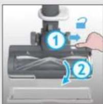
456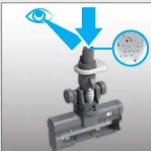
●
7. ERROR CODES AND TROUBLESHOOTING
5. CHARGING THE BATTERY
6. HOW TO USE THE VACUUM
6.1 STANDARD MODE
Using the product as a stick vacuum:
Setting the controls:
3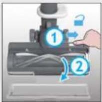
456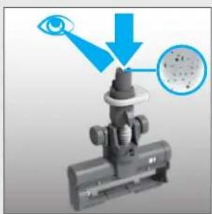
●
4. PREPARING YOUR VACUUM
Remove all parts of the product from the packaging and assemble your vacuum cleaner.
- STEP: Attach the tube to the floor nozzle.
- STEP: Attach the handle unit to the tube.

We have included a wall mount for additional storage.
6. USING THE VACUUM CLEANER
3 different operating modes are available for your vacuum cleaner:
- Standard mode (Stick Mode).
- Above-floor mode.
- Handheld mode.
6.1 STANDARD MODE (STICK MODE)
Command settings:
3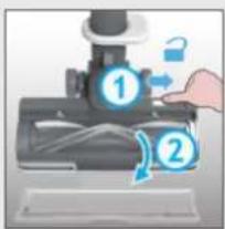
45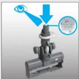
●
●
4. PREPARING YOUR VACUUM
5. REPLACING THE BATTERY
6. USING THE CLEANER
6.1 UPRIGHT MODE
Control settings:
3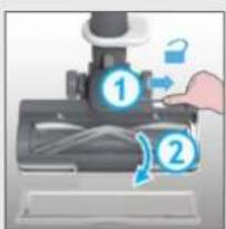
456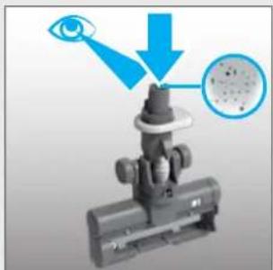
●
| Manufacturer Name | E-TEK Electronics Manufactory Co.LTD | |
| Manufacturer Address | 101, Workshop 1, No. 5, Jingye Road,Yanchaun Community, Yanlo Street, Bao’an District,518105, Shenzen, Guangdong, (PRC) | |
| Model | ZD024M268120BS | |
| Input Voltage | 100-240 V | |
| Input AC Frequency | 50/60 Hz | |
| Output Voltage | 26.8 V DC | |
| Output Current | 1.2 A | |
| Output Power | 32.16 W | |
| Average Active Efficiency | 87.2 % | |
| Efficiency at load 10% | 86.0% | |
| No-Load Power Consumption | 0.10 W |



- THE ENVIRONMENT
- IMPORTANT INFORMATION
- HOOVER SPARES AND CONSUMABLES
- QUALITY
- YOUR GUARANTEE
- YEAR BATTERY WARRANTY
- MAIN COMPONENTS
- PREPARING YOUR CLEANER
- CHARGING THE BATTERY
- USING YOUR CLEANER
- STICK MODE
- TO USE YOUR PRODUCT IN STICK MODE
- CONTROLS SETTINGS
- TO USE YOUR PRODUCT IN ABOVE FLOOR MODE
- TO USE YOUR PRODUCT IN HANDHELD MODE
- CONTROL SETTINGS
- CLEANER MAINTENANCE 7.1 EMPTYING THE DUST BIN
- CLEANER MAINTENANCE 7.2 FILTERS
- CLEANER MAINTENANCE
- FLOOR NOZZLE
- CLEANER MAINTENANCE 7.4 MINI-TURBO NOZZLE
- BLOCKAGES
- SAFETY INSTRUCTIONS FOR USE
- PREPARING THE DEVICE
- USING THE DEVICE
- SWEEP MODE
- MAINTENANCE OF THE VACUUM CLEANER
- MINI TURBO BRUSH
- USE OF THE DEVICE
- STANDARD MODE
- SETTINGS
- PREPARATION OF THE DEVICE
- ASSEMBLING YOUR VACUUM CLEANER
- USING YOUR VACUUM CLEANER
- STICK VACUUM MODE
- PREPARING YOUR VACUUM CLEANER
- USING YOUR DEVICE
- VERTICAL MODE
- USING THE APPLIANCE
- APPLIANCE MAINTENANCE
- OBSTRUCTIONS
- HOW TO PREPARE THE VACUUM CLEANER
- USING THE VACUUM CLEANER
- OPERATING OPTIONS
- EMPTYING THE DUST CONTAINER
- PREPARING THE VACUUM CLEANER
- CHARGE THE BATTERY
- USE
- ASSEMBLING THE DEVICE
- MAINTENANCE OF THE DEVICE
- CLOGGING
- INSTRUCTIONS FOR USE
- CORRECT USE
- BATTERY CHARGING
- HANDHELD MODE
- CORDLESS MODE
- ERROR CODES AND TROUBLESHOOTING
- HOW TO USE THE VACUUM
- USING THE PRODUCT AS A STICK VACUUM
- SETTING THE CONTROLS
- PREPARING YOUR VACUUM
- STANDARD MODE (STICK MODE)
- COMMAND SETTINGS
- REPLACING THE BATTERY
- USING THE CLEANER
- UPRIGHT MODE
Brand : CANDY
Model : HF910P 011
Category : Vacuum Cleaner