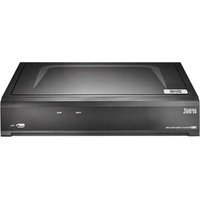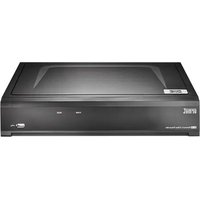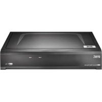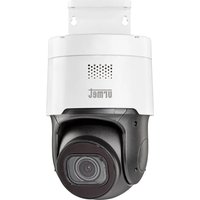
NVR 1098/326P - VCR GROTHE - Free user manual and instructions
Find the device manual for free NVR 1098/326P GROTHE in PDF.


User questions about NVR 1098/326P GROTHE
0 question about this device. Answer the ones you know or ask your own.
Ask a new question about this device
Download the instructions for your VCR in PDF format for free! Find your manual NVR 1098/326P - GROTHE and take your electronic device back in hand. On this page are published all the documents necessary for the use of your device. NVR 1098/326P by GROTHE.
USER MANUAL NVR 1098/326P GROTHE
natural_image
Simple 3D illustration of a rectangular block with a circular hole on top, set against a light blue background (no text or symbols)IT | EN | FR | DE
www.urmet.com
Quick Guide
NVR H.265 CON HDMI
Indice
text_image
Set Unlock Pattern Release your finger when done. Language Device ID New Admin N Password St New Admin F Confirm Pass Unlock Pattetext_image
Modifica telecamera IP Language: 3.0.01 Type: Language IP: 182 168.005.178 Password: 295.254.268.000 Language: 182 168.005.1681 Password: 9999 Name: https://www.mac.com/ Password: 182.001 Password: 182.001 Password: 182.001 Password: 182.001 Password: 182.001 Password: 182.001 Password: 182.001 Password: 182.001 Password: 182.001 Password: 182.001 OK Rename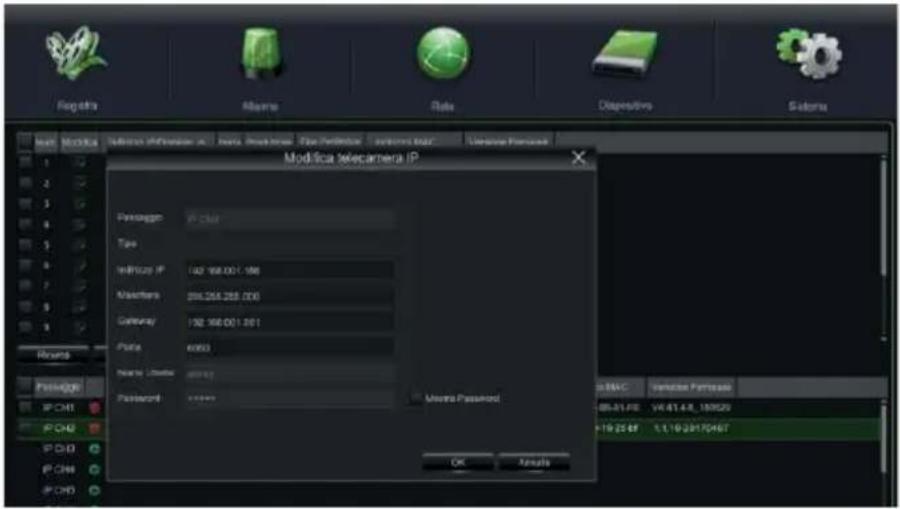
text_image
Registra Alarma Rate Dispersivo Sistema Modifica telecamera IP Passaggio IP: 100 Type Infricency IP: 102 168.00 C 186 Maserions: 256.254.258.000 Gateway: 192 168.00 C 1861 Ports: 6063 Name: Limite: 2000 Passion: 10000 Missa Passamort OK Results BMAC Verimise Passima 08-31.FE 14.41.4.8_189529 +19.25.67 1.1.19.29170467text_image
Ricerca Current Event Sub-joint Astart Tag File Exchange Website Resource Data: G020193 High Resources ✓ ✓ Resources ✓ Motion ✓ ISO ✓ FSI ✓ ISO ✓ LCD ✓ SCD ✓ FSI ✓ FSI ✓ ISO ✓ Zeros ✓ Documents ✓ Molecule Tips Stream: Main Struts Passages ✓ ✓ CHS ✓ CHS ✓ CHS ✓ CHS ✓ CHS ✓ CHS ✓ CHS ✓ CHS ✓ CHS ✓ CHS ✓ CHS ✓ CHS ✓ CHS ✓ CHS ✓ CHS ✓ CHS ✓ CHS ✓ CHS ✓ CHS ✓ CHS ✓ CHS ✓ CHS ✓ CHS ✓ CHS ✓ CHS ✓ CHH ✓ CHH ✓ CHH ✓ CHH ✓ CHH ✓ CHH ✓ CHH ✓ CHH ✓ IP Chn1 ✓ IP Chn2 © 2020Mtext_image
Devices Manual Adding Import Devices Online Device Select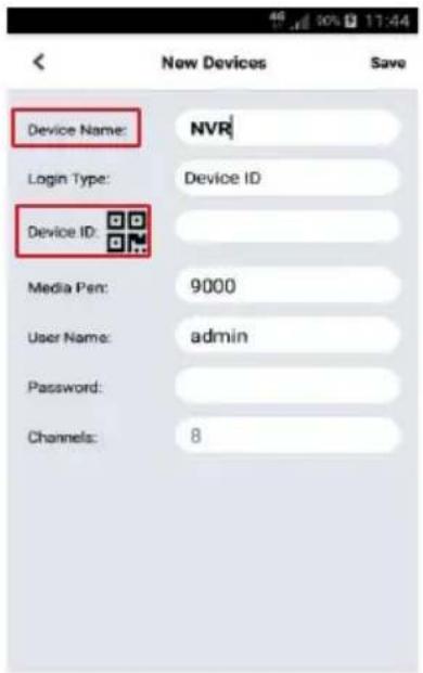
text_image
Device Name: NVR Login Type: Device ID Device ID: Media Pen: 9000 User Name: admin Password: Channels: 8text_image
User Info Username admin Password **** Device Info Start IP Media Port Web Port Gateway Net Mask Net Mode Static ModifyFirst access to the NVR....26
Starting up the NVR 27
DEVICE CONFIGURATION....27
IP CHANNEL CONFIGURATION 28
Recording and Playback 32
RECORDING PARAMETERS 32
PLAYBACK 34
Viewing from a Smartphone via QR Code....35
Viewing from a PC browser 37
Viewing from Client Software 39
QR Code 82
General Information
Dear Customer,
Thank you for purchasing this product.
This document describes how to quickly install and use the URMET S.p.A. H.265 series
NVR models. Before using the device, read this document carefully and keep in a safe place where it is easily accessible for reference when needed.
\*NOTE
For further information, see the instruction manual on the Urmet website. To download the manual from the site, see the QR code on the Addendum sheet.
WARNINGS
Power supply
Before connecting the device to the electrical outlet, ensure that the ratings on the nameplate match those of the mains power supply.
Do not pull on the cable to unplug the device.
Switch off the device before disconnecting the power. Do not switch the NVR off while recording or playing, or from the configuration menu. Stop recording and playback before disconnecting the device, to prevent damage to the hard disk.
Safety precautions
Keep the device away from rain and dampness to prevent the risk of fire or electrocution. Do not introduce any material (solid or liquid) inside it. If this should accidentally occur, disconnect the device from the mains outlet and have it inspected by qualified personnel.
Never open the device. In all cases, contact qualified personnel or an authorised service centre for repairs (www.urmet.com >> Contacts >> Technical Support Centres).
Keep the device away from children, to avoid accidental damage.
Do not touch the device with wet hands to prevent electric shock or mechanical damage.
Stop using the device if it falls or if the external casing is damaged. Continuing to use the device in these conditions could cause electric shock. Contact the retailer or authorised installer.
Installation precautions
To prevent the device from overheating, place it in a position that allows a flow of air through the vents in the casing. Leave a space of at least 5 cm when installing in a rack. For the same reason, do not install near heat sources such as radiators or hot air ducts.
Keep the device away from direct sunlight. Do not install in areas subject to excessive dust, mechanical vibration or shock.
Do not place the device on an unstable surface, such as an unsteady or sloping table, as the device could fall, causing damage or mechanical failure.
Do not install the device where it may be exposed to moisture or water. Do not spray water on the device, to avoid risk of fire, electric shock or mechanical damage.
Stop using the device if water or any other material penetrates inside it, to prevent risk of fire or electric shock. In such cases, contact the retailer or authorised installer.
Do not place heavy or heat-generating objects on top of the device: this could damage the casing and/or increase the internal temperature, leading to damage.
Do not cover the device with a cloth while it is running to prevent deforming the external casing and overheating the internal parts, causing risk of fire, electrocution and mechanical failure. Keep magnets and magnetised objects away from the device to avoid malfunction. Do not use the device in the presence of smoke, vapour, humidity, dust or intense vibrations.
Do not operate the device immediately after moving it from a cold place to a warm place or vice versa. Wait for around three hours: this will allow the device to adapt to the new ambient (temperature, humidity, etc.).
Cleaning the device
Rub gently with a dry cloth to remove dust and dirt.
Dip the cloth in a neutral detergent if dirt cannot be removed with a dry cloth alone.
Do not use spray products to clean the device. Do not clean the device using volatile liquids (such a petrol, alcohol, solvents, etc.) or chemically treated cloths to prevent deformation, deterioration or scratches to the paint finish.
Disconnect the device from the electrical outlet before any cleaning or maintenance operations.
Hard Disk
The hard disk installed in this device is sensitive to shock, temperature changes and vibrations. Failure to adopt suitable precautions could compromise the proper functioning of the device and cause loss of data from the hard disk.
If repairs are required, it is advisable to backup all important data before taking the device to the service centre.
Urmet S.p.A. is not liable for the loss of stored data.
Hard disks must be installed by qualified technical personnel or by contacting the technical support centre.
Image recording
This device was designed to record images. It is not a burglar alarm. URMET SpA cannot be held liable for loss or damage due to theft suffered by the user.
Make a test recording before using the device to ensure that it is working properly. URMET SpA is not liable for loss of stored data due to loss or damage caused by failure to follow the instructions for installation and use, improper use or malfunctioning of the device. This device contains precision electronic components. Protect the device from shocks to ensure proper image recording.
Privacy and Copyright
The NVR is a device for CCTV systems. The recording of images is subject to the laws in force in the country of use. Recording of images protected by copyright is forbidden.
Product users are responsible for checking and complying with all local rules and regulations regarding monitoring and the recording of video signals. The manufacturer SHALL NOT BE LIABLE for any use of this product not in compliance with the laws currently in force.
Software upgrade
Regularly check the specific section of the manufacturer's website at www.urmet.com >> Download >> Software for software upgrades.
Firmware upgrade
Contact URMET SpA Customer Service to check the availability of firmware upgrades.
Network configuration
The factory default IP address for the NVR is assigned via DHCP.
From the NVR Network OSD Menu, assign the NVR an IP address that has not been assigned to other devices in order to prevent any network conflict.
Once the NVR had been assigned a suitable address, it can be connected to the network.
Network connections
When connecting a remote PC (using client software or a browser), bear in mind that all video channels used by the PC correspond to a “unicast” type connection (TCP, RTP, UDP).
Installation
For rapid installation and use, connect the NVR to a monitor with a VGA or HDMI input and carefully follow the instructions below in the given order.
Rear panel on 1/2 HD NVR
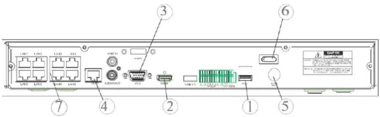
text_image
LAN1 LAN5 LAN3 LAN1 LAN3 LAN6 MAIN LAN2 VGA AUDIOOUT VGA USB 3.1 USB 3.2 USB 3.3 CAN OFF CAUT OFF ① ② ③ ④ ⑤ ⑥ ⑦Rear panel on 4 HD NVR
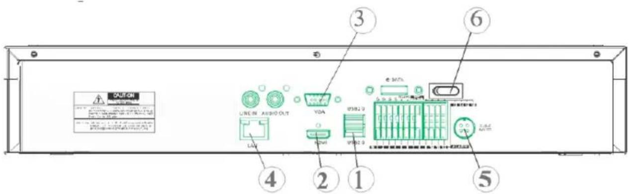
text_image
CAUT ON LINE IN AUDIO OUT VDA USB2.0 3 6 4 2 1 5① USB ports
② HDMI output
③ VGA port
④ Network connection port (to router, switch and PoE switch)
⑤ Power plug
⑥ Switches
⑦ PoE ports (available on the PoE model NVR) for direct connections to IP cameras (direct network cable)
Before installing the NVR, make sure the IP cameras are working and connected (via cable or WiFi) to the network that will be used by the NVR. For the IP camera network connection and configuration, see the instructions supplied with the cameras.
Installing the NVR
- Connect the mouse to the USB port ①.
- Connect the HDMI output ② or the VGA port ③ to the monitor to configure the IP cameras.
- Connect the network cable to the port ④.
Only for the PoE series:
- Connect one or more PoE IP cameras with network cables directly to one or more ports ⑦.
- Turn on the device by plugging it in ⑤ to the electrical mains and turning the switches ⑥ to the 1 position.
First access to the NVR
- The first time you switch on the NVR, you must immediately set the password in order to protect your privacy. Write down the username and password and keep them in a safe place.
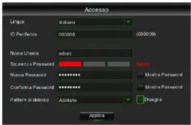
• Language: choose an OSD language
- Device ID: enter the device ID in brackets. Default ID: 000000.
- New Admin Name (Username): enter you administrator name.
- Password Strength: indicates the security level of the changed password.
- New Admin Password: enter your password. The password can be a combination of 8 characters.
- Confirm Password: enter your password once more.
- Enable Unlock Pattern: if this function is enabled, press Draw (pencil icon) to trace and confirm an unlock pattern; the set pattern must be traced each time to log in to the NVR system.
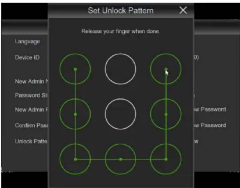
text_image
Set Unlock Pattern Release your finger when done. Language Device ID New Admin N Password St New Admin P Confirm Pass Unlock Patte- Click on Apply to confirm the settings and pass to the login interface. Enter the username and password to access the NVR system.
NOTE: if you forget your password and e-mail is deactivated, you will not be able to log in to the system; contact your retailer to reset the password.
Starting up the NVR
DEVICE CONFIGURATION
- Right click and enter the administrator password to access the NVR OSD menu. To check the firmware version currently installed in the NVR, access the menu page "System" -> "Info". If the version is not recent, the NVR system software (firmware) can be updated by following the instructions given in the complete User Manual available on the Urmet website (to download the manual from the site, see the QR code printed on the Addendum sheet).
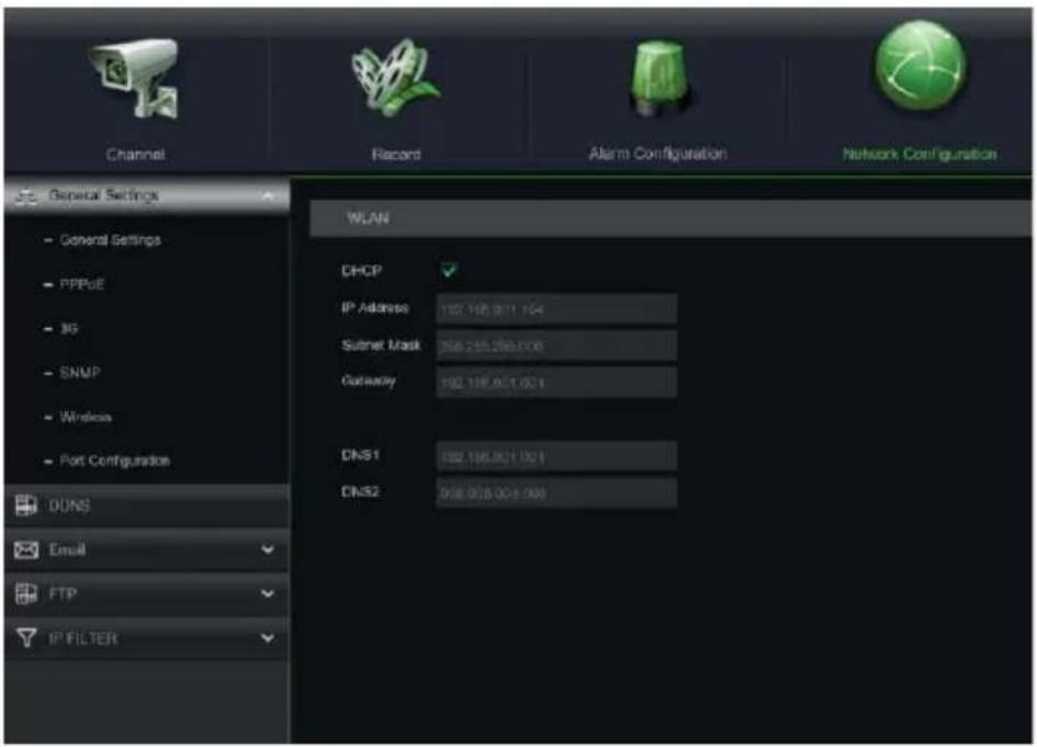
- View the network parameters currently in use in the NVR on the "Menu" -> "Network" page: wait about ten seconds for assignment and automatic display of the network parameters on the menu.
text_image
Channel Record Alarm Configuration Network Configuration General Settings - General Settings - PPPoE - 3G - SNMP - Wireless - Port Configurations DONS Email FTP IP FILTER WLAN DHCP IP Address 102.185.001.194 Subnet Mask 356.285.285.008 Gateway 102.185.001.001 DNS1 102.185.001.001 DNS2 356.058.001.008- If the LAN network does not support the DHCP service, go to the "Menu" -> "Network" page, change from "DHCP" to "Static" mode, and then manually enter the appropriate network parameters: IP address, Mask, Gateway, DNS.
IMPORTANT
For IP channel recording, make sure that the IP cameras have a static IP address to avoid loss of video signal. The IP camera address can be changed from dynamic to static using the button (see following steps).
IP CHANNEL CONFIGURATION
Before configuring the NVR IP channels, make sure that the IP cameras are working and are connected to the same network that will be used by the NVR. For IP camera network connection and configuration, see the instructions supplied with the cameras.
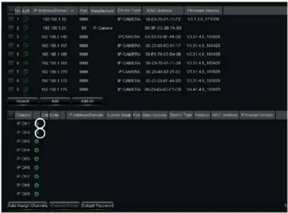
- To manually assign IP cameras to the NVR channels, click on the “+” button to add the IP camera to the relevant channel, as shown in Figure:
text_image
No Edit IP Address/Domain Port Manufacturer Device Type MAC Address Firmware Version 1 192.166.1.19 9988 IP CAMERA 50-E8-78-01-75-F2 V3.1.3.6_171206 2 192.166.1.23 80 IP Camera 00-0F-0D-29-7A-B8 3 192.168.1.140 9988 IPCAMERA 00-23-63-6F-44-D0 V3.31.4.8_180629 4 192.168.1.157 9988 IP CAMERA 00-23-53-6C-91-17 V3.31.4.8_180425 5 192.168.1.166 9988 IP CAMERA 58-E8-78-00-D4-58 V2.31.4.8_180426 6 192.168.1.169 9988 IP CAMERA 58-E8-78-01-71-39 V3.31.4.8_180425 7 192.168.1.170 9988 IPCAMERA 00-23-63-6F-25-03 V3.31.4.8_180629 8 192.168.1.172 9988 IP CAMERA 00-23-53-6F-44-B3 V3.31.4.8_180629 9 192.168.1.174 9988 IP CAMERA 00-23-63-6F-F7-CB V4.41.4.8_180629 Search Add Add All Channel Edit State IP Address/Domain Subset Mask Port Manufacturer Device Type Protocol MAC Address Firmware Version IP CH1 IP CH2 IP CH3 IP CH4 IP CH5 IP CH6 IP CH7 IP CH8 IP CH9 Auto Assign Channels Channel Details Default Password2. To continue manually adding IP cameras:
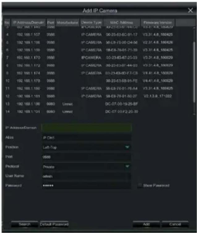
- Click on "Search" to find the IP cameras in the network, select the IP camera you want to add and enter the password (Default Password: admin), then check that the protocol and port are set correctly, as shown in the figure below. Select "Add" and wait for the device to come online (wait for the icon to turn green).
text_image
Add IP Camera No IP Address/Domain Port Manufacture Device Type MAC Address Framework Version 3 002.168.1.140 9580 IP CAMERA 00-23-63-6C-91-17 V3.31.4.8_180629 4 192.168.1.157 9580 IP CAMERA 00-23-63-6C-91-17 V3.31.4.8_180425 5 192.168.1.166 9580 IP CAMERA 58-E8-78-00-D4-56 V2.31.4.8_180426 6 192.168.1.169 9580 IP CAMERA 58-E8-78-01-71-39 V3.31.4.8_180425 7 192.168.1.170 9580 IPCAMERA 00-23-63-6C-25-03 V3.31.4.8_180629 8 192.168.1.172 9580 IP CAMERA 00-23-63-6C-44-33 V3.31.4.8_180629 9 192.168.1.174 9580 IP CAMERA 50-23-63-6C-F7-C8 V4.41.4.8_180629 10 192.168.1.175 9580 00-23-63-6C-91-FE V4.41.4.8_180629 11 192.168.1.180 9580 IP CAMERA 58-E8-78-01-76-A4 V3.31.4.8_180425 12 192.168.1.181 9580 IP CAMERA 58-E8-78-01-50-27 V2.13.8_17*222 13 192.168.1.190 9580 Ummel DC-07-00-19-25-BF 14 192.168.1.191 9580 Ummel DC-07-00-F2-20-39 IP Address/Command Alias IP CH1 Position Left-Top Port 9580 Protocol Private User Name admin Password **** Show Password Search Default Password Add Cancel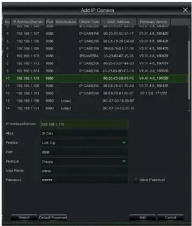
text_image
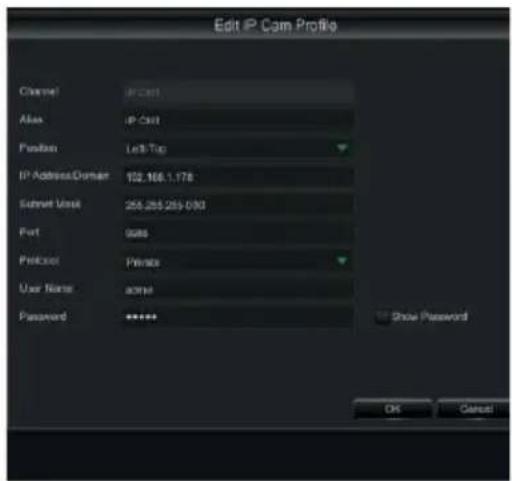
Add IP Camera No. IP Address/Domain Port Manufacture Device Type MAC Address Firmware Version 3 192.198.1.147 0560 IP CAMERA 00-23-63-07-78-24 V3.31.4.8_180625 4 192.198.1.157 0560 IP CAMERA 00-23-63-0C-01-17 V3.31.4.8_180425 5 192.198.1.166 0560 IP CAMERA 00-23-63-0D-04-56 V2.31.4.8_180426 6 192.198.1.169 0560 IP CAMERA 00-23-63-01-71-39 V3.31.4.8_180425 7 192.198.1.170 0560 IP CAMERA 00-23-63-07-25-03 V3.31.4.8_180629 8 192.198.1.172 0560 IP CAMERA 00-23-63-07-44-03 V3.31.4.8_180629 9 192.198.1.174 0560 IP CAMERA 00-23-63-0D-07-CB V4.41.4.8_180629 10 192.198.1.178 0560 00-23-63-08-01-FE V4.41.4.8_180629 11 192.198.1.180 0560 IP CAMERA 00-23-63-07-76-44 V3.31.4.8_180425 12 192.198.1.181 0560 IP CAMERA 00-23-63-01-50-27 V2.13.8_17*222 13 192.198.1.186 0560 Unmet DC-07-00-19-29-BF 14 192.198.1.191 0560 Unmet DC-07-09-F2-29-39 IP Address/Domain 162.198.1.176 Alias IP CHI Position Left-Top Port 0560 Protocol Private User Name admin Password **** Store Password Search Default Password Add Cancel- To change the data used by the NVR to connect each channel, select the button (also in the previous image).
text_image
Edit IP Cam Profile Channel: IP-Cast Access: IP-Cast Portion: Left/Top IP Address/Domain: 102.166.1.178 Submit Version: 258.255.255-030 Port: 988 Protocol: Private User Name: none Password: ****** Show Password OK Cancel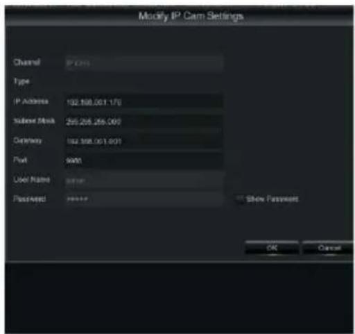
text_image
Modify IP Cam Settings Channel IP 2015 Type IP Address 192.168.061.170 Submit Mask 255.265.265.060 Delivery 192.168.061.601 Port 9400 User Name 9400 Password 9400 Show Password OK Cancel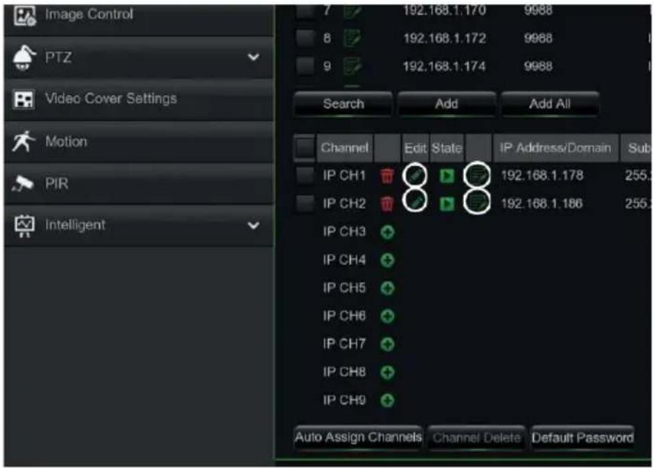
text_image
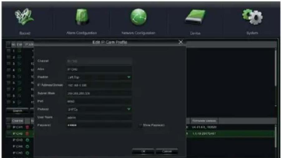
Image Control PTZ Video Cover Settings Motion PIR Intelligent 7 192.168.1.170 9988 8 192.168.1.172 9988 9 192.168.1.174 9988 Search Add Add All Channel Edit State IP Address/Domain Sub IP CH1 192.168.1.178 255. IP CH2 192.168.1.186 255. IP CH3 IP CH4 IP CH5 IP CH6 IP CH7 IP CH8 IP CH9 Auto Assign Channels Channel Delete Default PasswordTo change the network parameters of the connected camera (e.g.: camera IP address from DHCP to static, mask, Gateway, port) select the button (circle in the previous image).
text_image
Record Alarm Configuration Network Configuration Device System Edit IP Corn Profile Channel Alias IP-CHD Position Left Tap IP Address/Cluster 162.169.1.000 Subset Mask 350.265.265.000 Port 4450 Protocol U-PCO User Name: admin Penset: ***** (New Festival) Forward Version: 14.67.6.8_183520 1.1.19.20170407 OK Cancel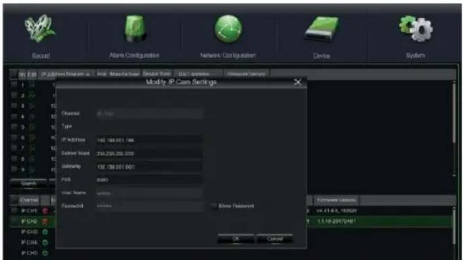
text_image
Record Alarm Configuration Network Configuration Device System Modify IP Cam Settings Checked 87,100 Type IP Address 192.156.001.186 Solder Maps 318.256.258.000 Gateway 192.156.001.001 Pack 6383 User Name: 00000 Password: 00000 Show Password OK Cancel Features Version: V4.47.6.8_183529 1.1.10.2017/497- The NVR is configured to automatically start the continuous recording of the cameras assigned to the channels. Check that the red "•" symbol is displayed on the monitor for each camera.
- In the LIVE preview grid, by default, the NVR displays the MAINSTREAM of all the IP cameras enabled and configured. However, if the decoding resources are insufficient, the NVR automatically displays the SUBSTREAM of the channels.
- When the "Insufficient Resources" message is displayed next to the IP channels in the LIVE preview grid, the MAINSTREAM or SUBSTREAM frame-rate and bitrate settings should be reduced on the IP channel settings page of the NVR OSD menu: "Main Menu" -> "Parameter" -> "Record" -> " mainstream" or "Main Menu" -> "Parameter" -> "Record" -> "SubStream".
- If the IP camera web interface is used to change its parameters (e.g. Mainstream, Substream or Mobile Stream), the NVR must be restarted so that the changes on the camera are also displayed in the menu parameters of the corresponding channel on the NVR.
- Once the network configuration is completed, the NVR and cameras can be remotely viewed using the URMET iUVS plus app on an iOS or Android smartphone or from a PC using Internet Explorer / Firefox or Urmet UVS client software.
\*NOTE
- The Password should be changed after installation.
- If the IP camera is not detected, try adding it manually.
- For further details, see the complete instruction manual on the Urmet website (to download the manual, see the QR code printed in the specific section on this Quick Guide).
NVR CHANNEL CONFIGURATION FROM A PC
To add the device quickly from a PC, without needing to connect it to a monitor, see the complete manual for the device, which can be read and downloaded from the Urmet website (to download the manual, see the QR code printed on this Quick Guide).
Recording and Playback
RECORDING PARAMETERS
Select "Menu" -> "Recording" to access the recording menu. The following functions are available:
- The "Schedule" menu allows you to set the recording options: 24 hours or Normal, on Motion/Alarm; recording timetables can be customised. Both recording options, Normal/Alarm, can be set within the same timetables.
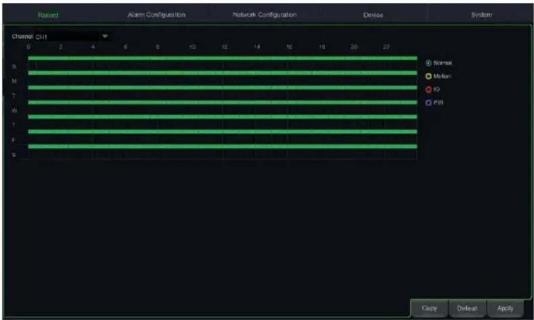
text_image
Record Alarm Configuration Network Configuration Device System Channel CH1 S M T W T P S Normal Motion IO PIR Copy Defeat Apply- In the "Recording" menu you can set the stream to be recorded: Mainstream or DualStream (Mainstream + Substream).
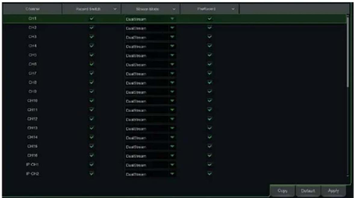
text_image
Channel Recent Switch Stream Mode PreRecord CH1 DualStream CH2 DualStream CH3 DualStream CH4 DualStream CH5 DualStream CH6 DualStream CH7 DualStream CH8 DualStream CH9 DualStream CH10 DualStream CH11 DualStream CH12 DualStream CH13 DualStream CH14 DualStream CH15 DualStream CH16 DualStream IP CH1 DualStream IP CH2 DualStream Copy Default ApplyThe device manages different video streams for each IP input, as follows:
• Mainstream: maximum resolution stream, used for video recording to Hard Disk and display on a local network
- Substream: medium resolution stream for display in a multi-screen room or remote viewing
- Mobile stream: optional stream that can only be activated if supported by the IP camera. This is a low-resolution stream for remote viewing.
To configure each stream, open the "Recording" -> "Coding" page in the OSD menu and select the stream to configure:
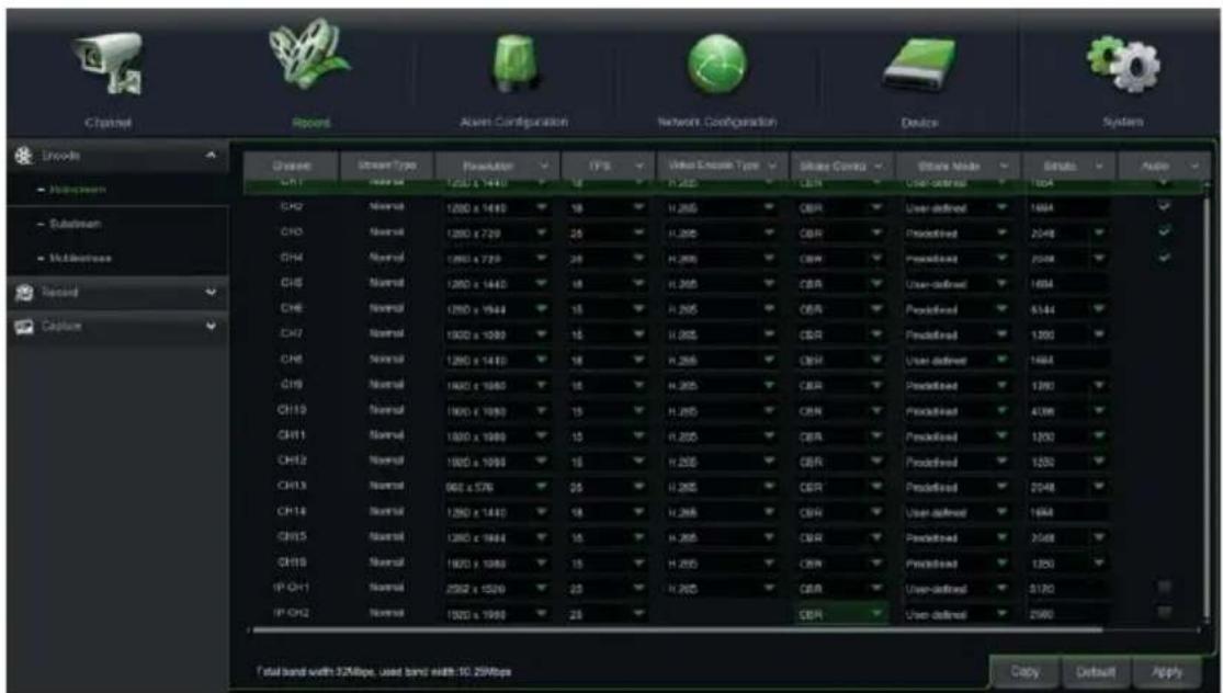
text_image
Channel Record Alert Configuration Network Configuration Device System Chase Stream Type Resolution FPS Video Stream Type Share Coverage Database Mode Strike Audio CH1 Normal 1200 x 1440 18 H.265 CER User-defined 1684 CH2 Normal 1200 x 720 25 H.265 CER Predefined 2048 CH3 Normal 1200 x 720 25 H.265 CER Predefined 2048 CH4 Normal 1200 x 1440 18 H.265 CER User-defined 1684 CH5 Normal 1200 x 1644 15 H.265 CER Predefined 4144 CH6 Normal 1200 x 1990 15 H.265 CER Predefined 1390 CH7 Normal 1200 x 1440 18 H.265 CER User-defined 1684 CH8 Normal 1200 x 1680 15 H.265 CER Predefined 1390 CH9 Normal 1200 x 1990 15 H.265 CER Predefined 4098 CH10 Normal 1200 x 1990 15 H.265 CER Predefined 1390 CH11 Normal 1200 x 1990 15 H.265 CER Predefined 1390 CH12 Normal 1200 x 1990 15 H.265 CER Predefined 1390 CH13 Normal 960 x 576 25 H.265 CER Predefined 2048 CH14 Normal 1200 x 1440 18 H.265 CER User-defined 1684 CH15 Normal 1200 x 1684 15Once the settings have been made on the Recording menu, save the changes, exit the device menu and then check that the “•” icon is displayed for each channel in LIVE mode, which shows that the device is recording in accordance with the set parameters.
IMPORTANT
The default factory settings are those recommended for video streams in order to obtain the right balance between video quality and fluidity, both for recording and LIVE display, locally or remotely. Streaming parameters can, however, be set differently to the factory ones described above.
PLAYBACK
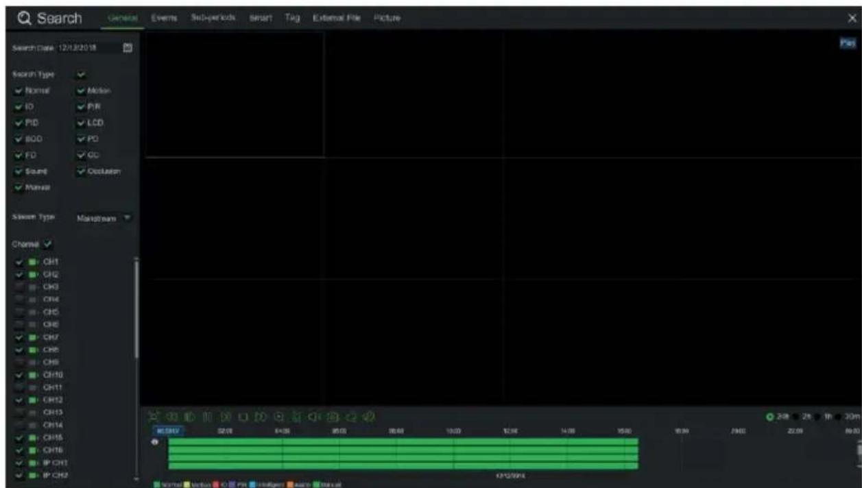
Right click on the mouse in LIVE view and press the "Play" button on the popup menu that appears at the bottom of the LIVE grid, to access the interface shown below.
Then select the channel you want to playback and click on the "Play" button to access the playback mode shown above.
You can use the Playback control bar to activate Fast Forward (X2, X4 and X8), Slow Play (1/2, 1/4 and 1/8 speed), Play, Pause/Frame and Rewind (X2, X4 and X8).
At the end of playback, the NVR will return to the previous menu, shown below.
The Play control bar displays the progress of the current playback, as shown below. When clicking on any point of the control bar, if there are no recorded files at that point, the system returns to the previous menu.
text_image
Search General Events Sub-periods Smart Tag External File Picture Search Date: 12/13/2018 Search Type Normal Motion IO P/R PID LCD BOD PD FD GC Sound Occlusion Normal Stream Type Mainstream Channel CH1 CH2 CH3 CH4 CH5 CH6 CH7 CH8 CH9 CH10 CH11 CH12 CH13 CH14 CH15 CH16 IP CH17 IP CH18 MCSPV 52.00 64.00 95.00 26.00 13.00 12.00 14.00 15.00 15.00 24.00 26.00 In 30m Moral Verbal O P/N Intelligent Auto ManualViewing from a Smartphone via QR Code
Once the NVR and cameras are configured in the network, for remote viewing on an iPhone or Android smartphone, download the URMET iUVS plus app from the respective stores.
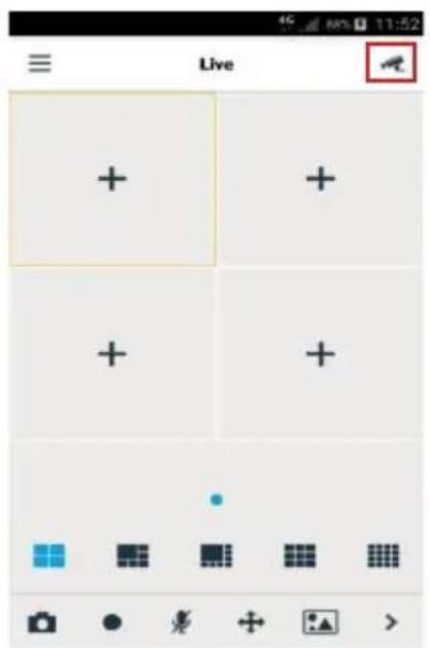
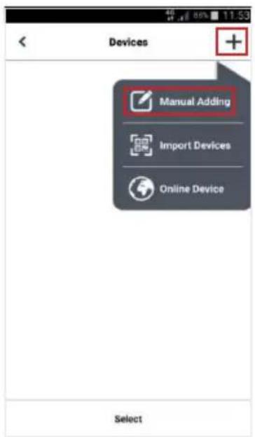
After downloading and installing the app, you can add and view the NVR on a smartphone via a P2P connection as follows:
text_image
Live + + + + + + + + + + + + + + + + + + + + + + + + + + + + + + + + + + + + + + + + + + + + + + + + + + + + + + + + + + + + + + + + + + + + + + + + + + + + + + + + + + + + + + + + + + + + + + + + + + + + +
text_image
Devices Manual Adding Import Devices Online Device Select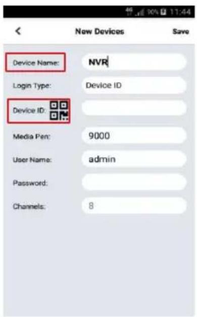
text_image
Device Name: NVR Login Type: Device ID Device ID: Media Pen: 9000 User Name: admin Password: Channels: 8Fill in the "Device name" field. Select the ☐con to enter the NVR ID by reading it from the QR code. Install a QR code reader app on the smartphone, if necessary, and then scan the QR on the NVR case.
text_image
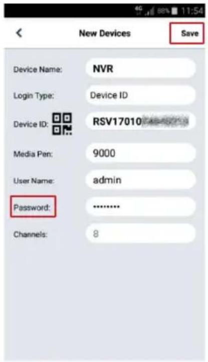
New Devices Save Device Name: NVR Login Type: Device ID Device ID: RSV17010 Media Pen: 9000 User Name: admin Password: ---------------- Channels: 8Enter the NVR password in the "Password" field, press "Save" and wait for about ten seconds until the NVR LIVE video is loaded automatically.

text_image
Live 02/05/2014 08:37:04 OffIMPORTANT
- In addition to P2P mode, the NVR can also be remotely displayed on a smartphone with the Urmet DDNS service (for which, the router must be set for port opening and forwarding). For further details about using the Urmet DDNS, service, see the complete NVR manual (to download the manual, see the QR code printed on the Addendum sheet).
- To display the NVR on a local (LAN) network, it can be added to the app via the IP address. To know the local IP address of the NVR, see the "Menu" -> "Networks" page in the NVR menu.
Viewing from a PC browser
Once the NVR and cameras are configured in the network, you can connect to the NVR via a browser from:
• A PC with a Windows operating system and an Internet Explorer or Firefox browser
• A MAC with a 10.8.0 operating system or higher and a Safari browser version 6.0 or higher.
The PC or MAC must be connected to the same local network (LAN) as the NVR.
To connect to the NVR (for Windows systems only), perform the following operations:
- Install the "Device Config Tool" software from the CD supplied with the product on a PC with a Windows operating system connected to the same network as the NVR. Once installed, the software will detect the NVR in the local area network and display it in the list.
- If the LAN to which the NVR is connected has an automatic address service (DHCP), the NVR will be automatically assigned a valid IP address, which will appear in the list in the "Device Config Tool" screen:

text_image
Device Search Search Upgrade Config Filtration IP No. IP Media Port Web Port Channel Device Name Device Version Net M 1 192.168.1.169 9000 80 4 1098/318D1 V8.1.0-20191108 05 255.255- If the LAN network to which the NVR is connected does not support the DHCP service, an IP address must be assigned manually to the device. To do this, set the required network parameters to be assigned to the NVR at the bottom of the "Device Config Tool" screen: IP, Gateway, Net Mask, then enter the password and press "Modify" to save the network parameters in the NVR settings:

text_image
User Info Username admin Password ***** Device Info Start IP Media Port Web Port Gateway Net Mask Net Mode Static Modify- Now click on the NVR IP address displayed in the "Device Config Tool" list to open Internet Explorer automatically. At the first connection, the browser will require the installation of a software component (ActiveX, in the case of Internet Explorer), which is downloaded directly by the NVR. Accept the installation of the component and continue. For further details, see the complete instruction manual on the Urmet website (to download the manual, see the QR code printed on the Addendum sheet).
- The NVR can also be reached without using the "Device Config Tool" software by opening your browser (Internet Explorer or Firefox for Windows, Safari for Mac) and typing in the IP address in the navigation bar. To know the NVR IP address, open the "Menu" -> "Network" page on the NVR monitor.
-
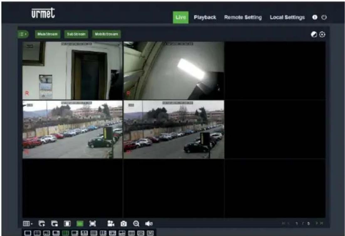
- Once the component has been installed, the browser will display the login page: enter the NVR password and press "Login" to start the connection and display the video streams inside the browser window.
text_image
urmet Live Playback Remote Setting Local Settings Main Stream Sub Stream Mobile Stream R R R B BFor further details about using the NVR from a browser, see the complete manual available on the Urmet website (to download the manual, see the QR code printed on the Addendum sheet).
Viewing from Client Software
You can also simultaneously connect to one or more NVRs with the URMET UVS client software included in the CD provided with the product. The URMET UVS software is available in two versions: for Windows and for the Mac OS version 10.8.0 or higher.
For details on installing and using the URMET UVS client software, see the full manual on the provided CD or on the Urmet website.
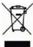
DIRECTIVE 2012/19/EU OF THE EUROPEAN PARLIAMENT AND OF THE COUNCIL of 4 July 2012 on waste electrical and electronic equipment (WEEE).
The crossed-out wheeled bin symbol on the product or on its packaging indicates that the product must not be disposed of together with ordinary household waste.
The user must therefore dispose of the waste equipment by taking it to a designated collection centre for the recycling of waste electrical and electronic equipment. As an alternative to independent disposal,
you can hand in the equipment you wish to dispose of to the retailer when purchasing a new appliance of the same type.
Electronic products up to 25 cm in size can also be handed in for free disposal, with no purchase obligation, at electronics stores with sales areas of over 400 m ^2 .
Adequate separate collection for recycling, treatment and environmentally friendly disposal of the scrapped equipment helps to prevent negative impacts on the environment and on human health, and promotes recycling and/or reuse of the materials with which the equipment is made.
Quick Guide
NVR H.265 AVEC HDMI
Table des matières
text_image
Set Unlock Pattern Release your finger when done. Language Device ID New Admin N Password St New Admin F Confirm Pass Unlock Pattetext_image
Canal Disseler enregistrement Mode de Out Péa-enregistre CA1 ✓ DoubleStream ✓ CA2 ✓ DoubleStream ✓ CA3 ✓ DoubleStream ✓ CA4 ✓ DoubleStream ✓ CA5 ✓ DoubleStream ✓ CA6 ✓ DoubleStream ✓ CA7 ✓ DoubleStream ✓ CA8 ✓ DoubleStream ✓ CA9 ✓ DoubleStream ✓ CA10 ✓ DoubleStream ✓ CA11 ✓ DoubleStream ✓ CA12 ✓ DoubleStream ✓ CA13 ✓ DoubleStream ✓ CA14 ✓ DoubleStream ✓ CA15 ✓ DoubleStream ✓ CA16 ✓ DoubleStream ✓ IP CA1 ✓ DoubleStream ✓ IP CA2 ✓ DoubleStream ✓ Copier Par défaut Applytext_image
Devices Manual Adding Import Devices Online Device Select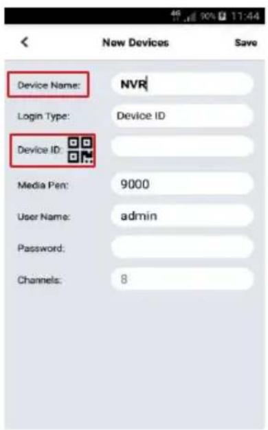
text_image
Device Name: NVR Login Type: Device ID Device ID: Media Pen: 9000 User Name: admin Password: Channels: 8text_image
User Info Username admin Password **** Device Info Start IP Media Port Web Port Gateway Net Mask Net Mode Static Modifytext_image
Set Unlock Pattern Release your finger when done. Language Device ID New Admin N Password St New Admin P Confirm Pass Unlock Pattetext_image
Devices Manual Adding Import Devices Online Device Select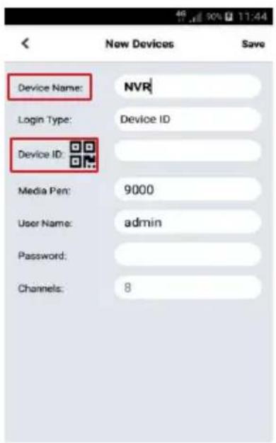
text_image
Device Name: NVR Login Type: Device ID Device ID: Media Pen: 9000 User Name: admin Password: Channels: 8text_image
User Info Username admin Password **** Device Info Start IP Media Port Web Port Gateway Net Mask Net Mode Static Modifytext_image
QR code image containing encoded data, no visible human-readable text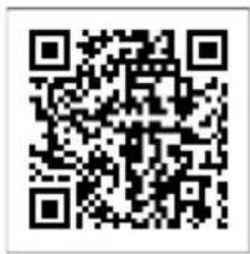
text_image
QR code image containing encoded data, no visible human-readable text1098/318
text_image
QR code image containing encoded data, no visible human-readable text1098/318P
text_image
QR code image containing encoded data, no visible human-readable text1098/332
text_image
QR code image containing encoded data, no visible human-readable textEN
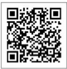
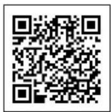
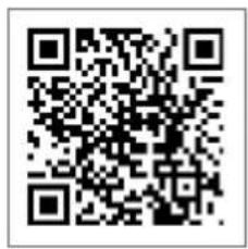
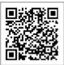
The updated version of this quick start guide, the complete manual, the software and firmware of the devices are available for download at www.urmet.com. Open the page dedicated to the product by scanning the QR code below with your smartphone and then select the section DOCUMENTATION AND RESOURCES.
FR
text_image
QR code image containing encoded data, no visible human-readable text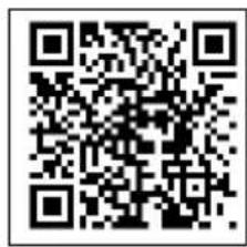
text_image
QR code image containing encoded data, no visible human-readable text1098/332
text_image
QR code image containing encoded data, no visible human-readable textMADE IN CHINA