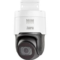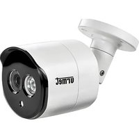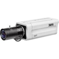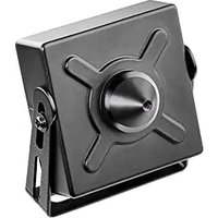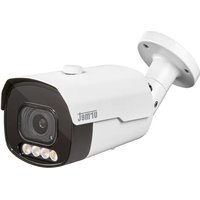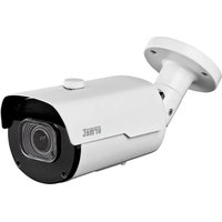
VK 1099/401A - Surveillance Camera GROTHE - Free user manual and instructions
Find the device manual for free VK 1099/401A GROTHE in PDF.


User questions about VK 1099/401A GROTHE
0 question about this device. Answer the ones you know or ask your own.
Ask a new question about this device
Download the instructions for your Surveillance Camera in PDF format for free! Find your manual VK 1099/401A - GROTHE and take your electronic device back in hand. On this page are published all the documents necessary for the use of your device. VK 1099/401A by GROTHE.
USER MANUAL VK 1099/401A GROTHE
DISPOSITIVISMARTPHONE 24
DISPOSITIVISMARTPHONE
Umet iUVS plus Software Mobile
CONNECTION TO IP NETWORK WITH DHCP SERVICE 37
PTZ CONTROL 41
MOTION ALARM MANAGEMENT 44
PIR ALARM MANAGEMENT 44
DETERRENCE FUNCTION CHECK (only for model 1099/208) 45
SOUND ALARM MANAGEMENT 46
Mobile software 46
SMARTPHONE DEVICE 46
General information
Dear Customer,
Thank you for purchasing this product.
This quick start guide was written to help you set up H.265 IP Camera Series rapidly and easily.
Read this quick start guide which contains information for correct, safe use carefully before using the device.
Keep this guide at hand so that you can refer to it when needed.
\*NOTE
For more detailed information about the devices, refer to the complete user manual available on the Uromet website (see QR code printed on the Addendum sheet).
WARNING
Electricity
Before connecting to electrical outlet, verify the electrical specifications of the device are suitable for the available power source.
We suggest to connect the device to electrical outlet via a switch disconnector.
In case of malfunctioning, disconnect electrical power from the general switch.
Use only the provided power supply.
Safety precautions
Do not expose the device to rain or humidity and do not insert any solid or liquid object in it to prevent the risk of fire or electrocution. In these events disconnect the device from the electrical outlet and call technical assistance to check it.
Do not open the device. Any repair must be made by qualified personnel or by calling the nearest authorized technical assistance center (www.urmet.com >> Contacts).
Keep the device away from children to prevent any, even involuntary, damaging.
Do not touch the device with wet hands as it might cause electrical shock or mechanical damages.
If the device falls down while working or if the salesbox is damaged, do not continue using it. If usage is continued under such circumstances electrical shocks might take place.
Contact the authorized retailer or installer.
Installation precautions
Do not install the camera in places with possible exposure to rain or humidity without the proper protective case.
Do not point the camera directly to sunlight or other intense sources of light, even when turned off. The subject of recording must not be against the light.
Do not point the camera against reflective objects.
Some light conditions (such as fluorescent color) can affect the recorded colors. Use
AUTO-IRIS lens when operating the camera in changing light environments.
Do not use this device on any unstable support such as lurching or sloping table to prevent the device from falling and be damaged.
If water or any other material should penetrate the camera, stop using it as it might cause fire or electrical shock and contact the authorized retailer or installer.
Do not cover the device with any cloth while using to prevent deformation of the external part and inner components heating which might provoke fire, electrical shock or mechanical damages.
Do not put magnets or magnetized objects close to the device to prevent functional anomalies.
Do not use this device in presence of smoke, steam, humidity, dust or intense vibrations. Do not use the device shortly after moving it from warm to cold environment and vice versa. After moving the device wait three hours before using it: this time is necessary for the device to adapt to the new environment (temperature, humidity, etc.).
Usage precautions
Check the device is not damaged after removing the packaging.
Check the working environment is not too humid and the temperature is within the indicated range.
Do not point the camera against sunlight to prevent sensor damages.
Device cleaning
Use a dry cloth to remove dust and dirt from the device.
If dirt cannot be removed with a dry cloth, use a humid cloth and a neutral cleanser.
Do not use spray cleanser for device cleaning. Do not use volatile liquids such as gasoline, alcohol, solvents etc. or chemical treated cloth to clean the device to prevent deformations, damages or scars on the finishing paint.
Disconnect the device from the electrical outlet before cleaning.
Video recording
This device is not designed as a burglar system but mainly to transmit and record video images. URMET S.p.A. is not in any way responsible for loss or damages of the user consequent to theft.
Before using the device, record a demo video to verify the correct functionality of this feature. URMET S.p.A. is not in any way responsible for loss of recorded data consequent to wrong setting or usage, device malfunctioning or failure.
This device is composed by electronic precision components. Do not hit the device while recording as it might affect the video.
Privacy and Copyright
The IP camera is designed for surveillance systems. Video recording is subject to the laws applicable to the Country where used. It is forbidden to record images with Copyright.
The User is responsible to check and respect all local laws and norms for video signal
recording. The manufacturer is NOT in any way liable for any usage of the product which might result not compliant to the relevant norms.
Firmware upgrade
Contact Customer Service Technical Assistance URMET S.p.a. in order to check availability of firmware upgrades.
Network configuration
Camera default setting is DHCP mode. If the network does not support dynamic addressing (DHCP), the device will automatically switch to factory IP 192.168.1.168. Use Umet "Device Config. Tool" software provided with IP Camera CD in order to modify the IP address and other network settings to prevent any conflict with other devices on the network.
Network connections
When connecting a PC (using Software Client or Browser), any video channel on the PC will be using "unicast" connection (TCP, RTP, UDP).
The device can support up to 10 "unicast" connections so it is possible to show the video on maximum 10 remote devices (PC or smartphone) at the same time depending on the available network band .
Installation
INSTALLATION OF BULLET CAMERAS
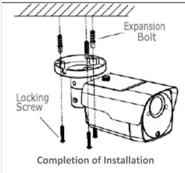
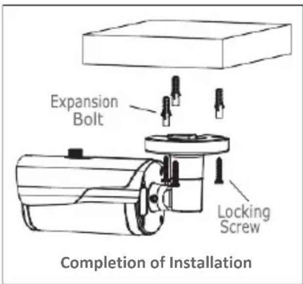
Ceiling Mounting
Insert three expansion bolts in place into the ceiling and fix the equipment with three locking screws
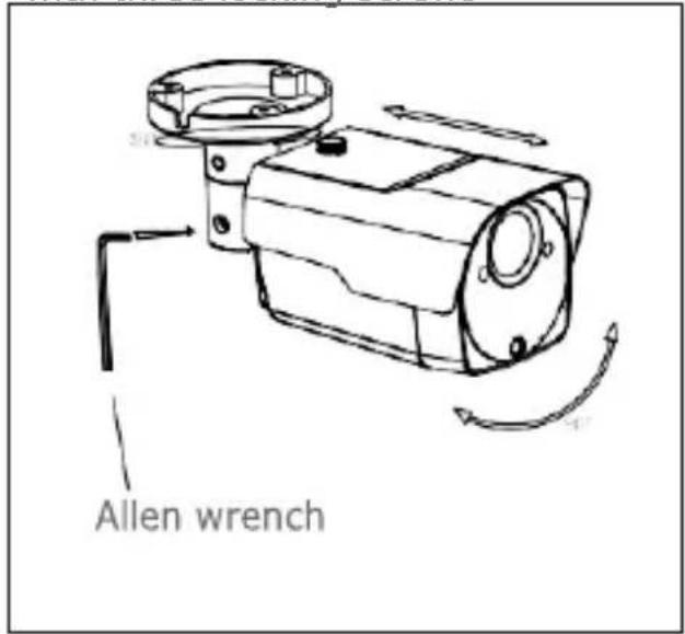
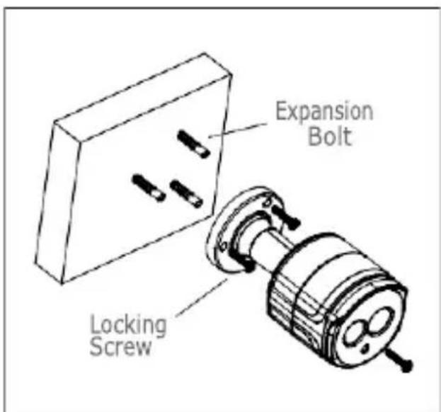
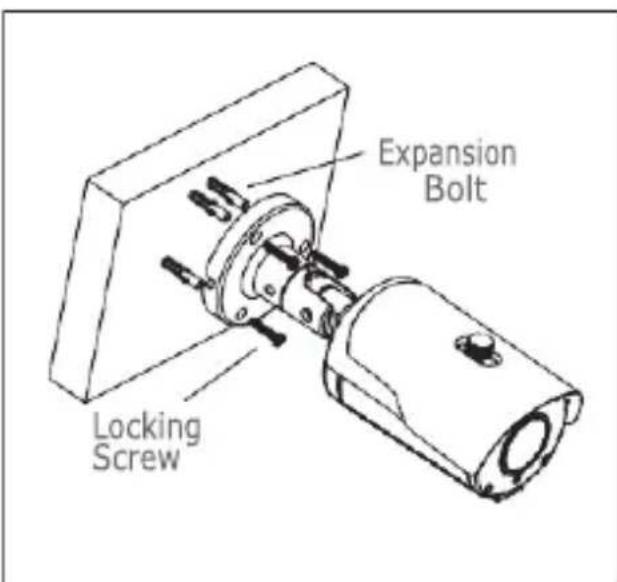
Wall Mounting
Insert three expansion bolts in place into the wall and fix the equipment with three locking screws.
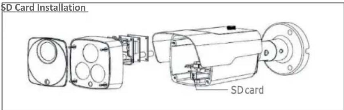
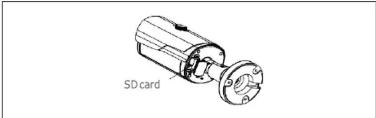
SD Card installation model 1099/208
ATTENTION: this operation must be carried out by qualified personnel.
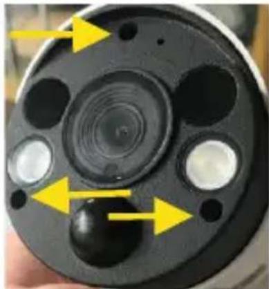
Remove the 3 screws that lock the front cover
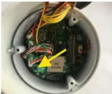
- Remove the screw that secures the SD Card slot
- Insert the SD Card into the slot
- Reinsert the the SD Card slot on the motherboard
- Reinsert the screw that secures the SD Card slot
INSTALLATION OF MINI DOME CAMERAS
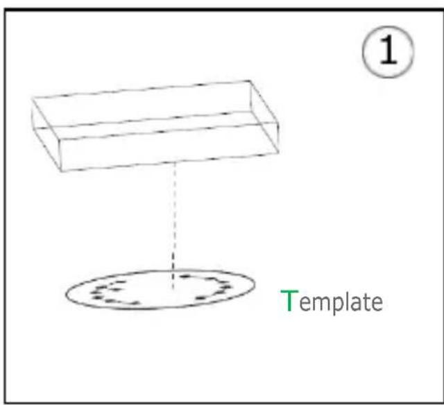
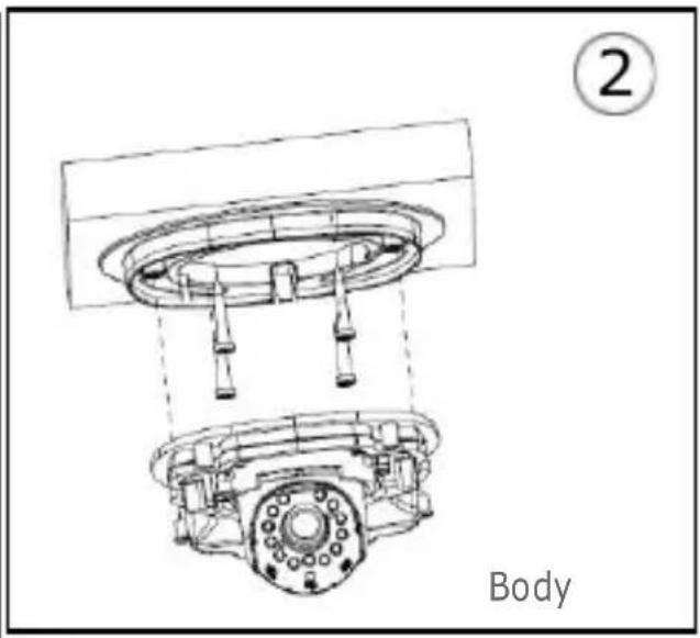
Ceiling Mounting
- Paste the sticker in place at the proper position as selected.
- Remove the collar off the camera by rotating it down.
- Fix the pedestal by drilling locking holes around the sticker and inserting three expansion bolts into the holes and fastening it with three locking screws.
- Adjust it to an appropriate angle.
- Mount the collar back by rotating it up.
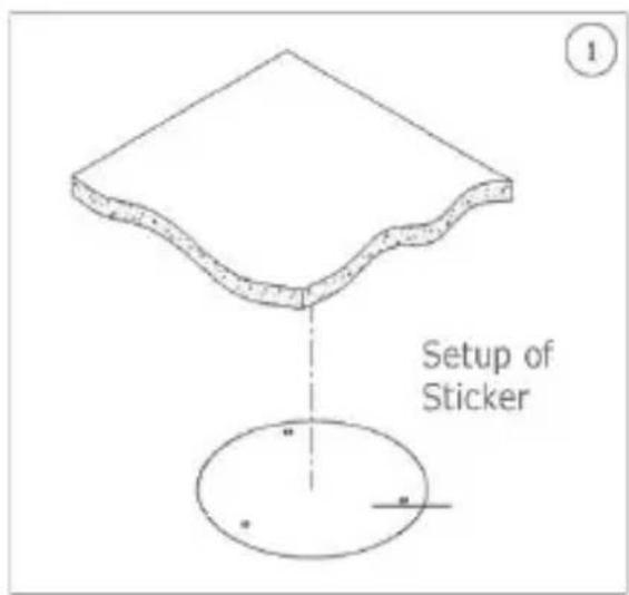
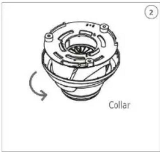
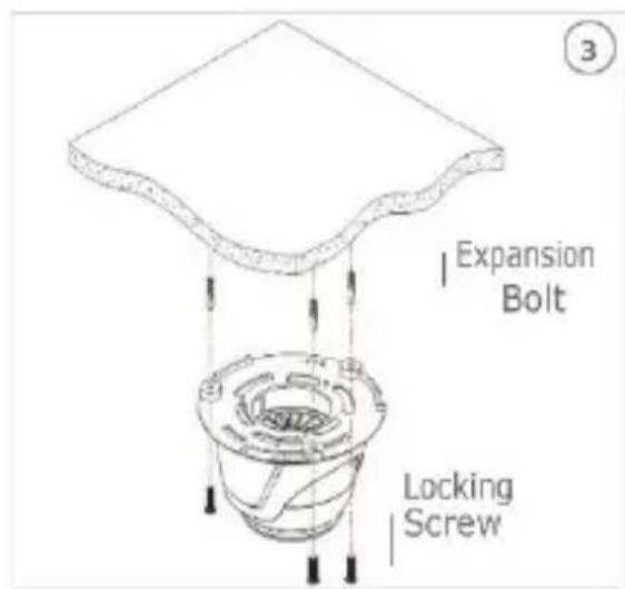
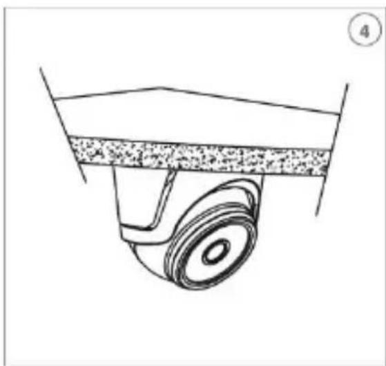
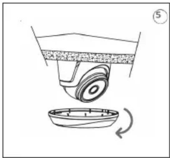
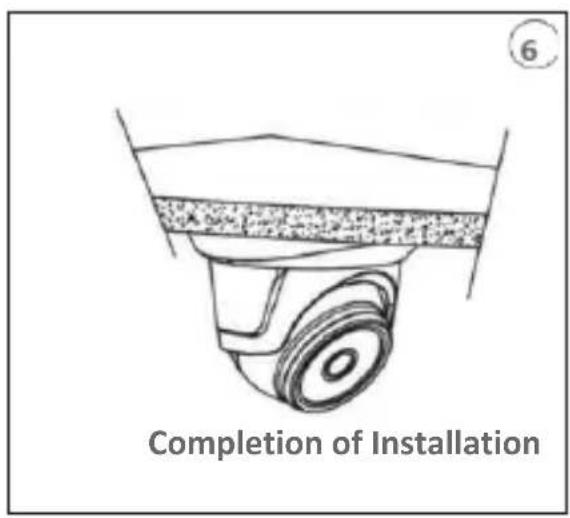
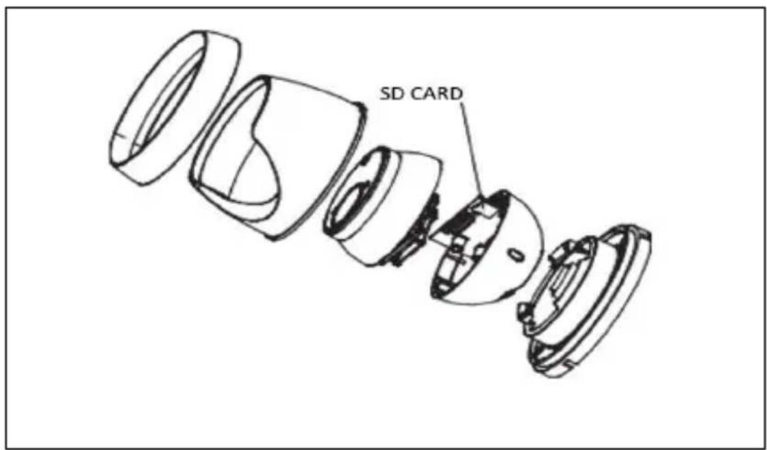
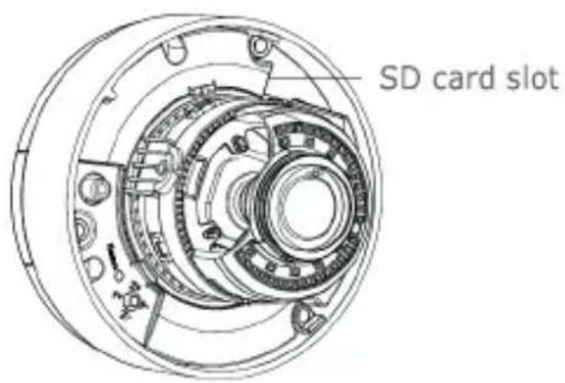
SD Card Installatio
MINI FLAT CAMERA INSTALLATION
Ceiling fixing
- Fasten the fixing bracket to the ceiling.
- Fasten the camera body to the ceiling.
- Correctly adjust the angle by rotating the camera body.
- Apply the dome cover of the camera

Installazione SD Card
Insert the SD Card in the slot indicated by the arrow
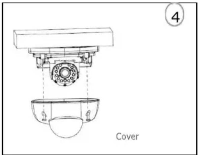
INSTALLATION OF VANDAL-PROOF DOME CAMERAS
Ceiling Mounting
- Paste the sticker in place at the proper position as selected.
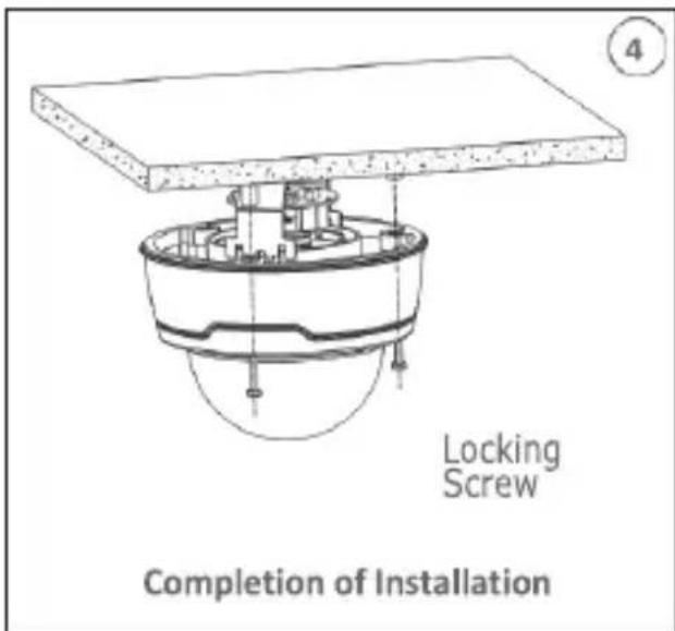
- Remove the front component by loosening the three locking screws with a screwdriver.
- Fix the pedestal by drilling locking holes around the sticker and inserting four expansion bolts into the holes and fastening it with four locking screws. Adjust it to an appropriate angle.
- x the front component on the pedestal by tightening the three locking screws.
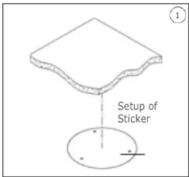
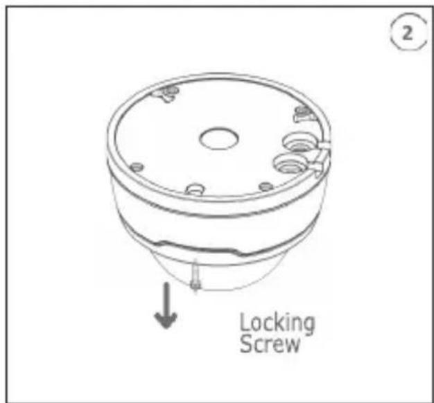
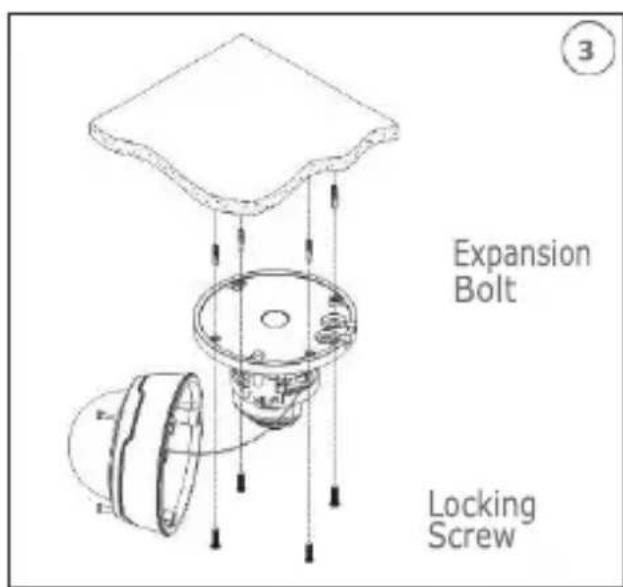
IP Camera Configurations
The camera must be configured for the home or office network after it has been powered. It is advisable to install and configure one camera at a time if you are installing multiple cameras on the same network.
CONNECTION TOIP NETWORK WITH DHCP SERVICE
For Quick installation about IP camera with dynamic host configuration (DHCP) on the network will be assigned an IP address automatically. IF DHCP Service is not supported, the default IP Address of IP Camera will be 192.168.1.168.
IP Camera Configuration:
- Install the Software "Device Config. Tool" provided by CD and follow the installation instructions displayed at monitor.
- Launch the "Device Config. Tool" Software, selecting it will be displayed automatically IP Address, Subnet Mask, Gateway, and MAC Address for each IP Camera detected in LAN, as shown in picture below.
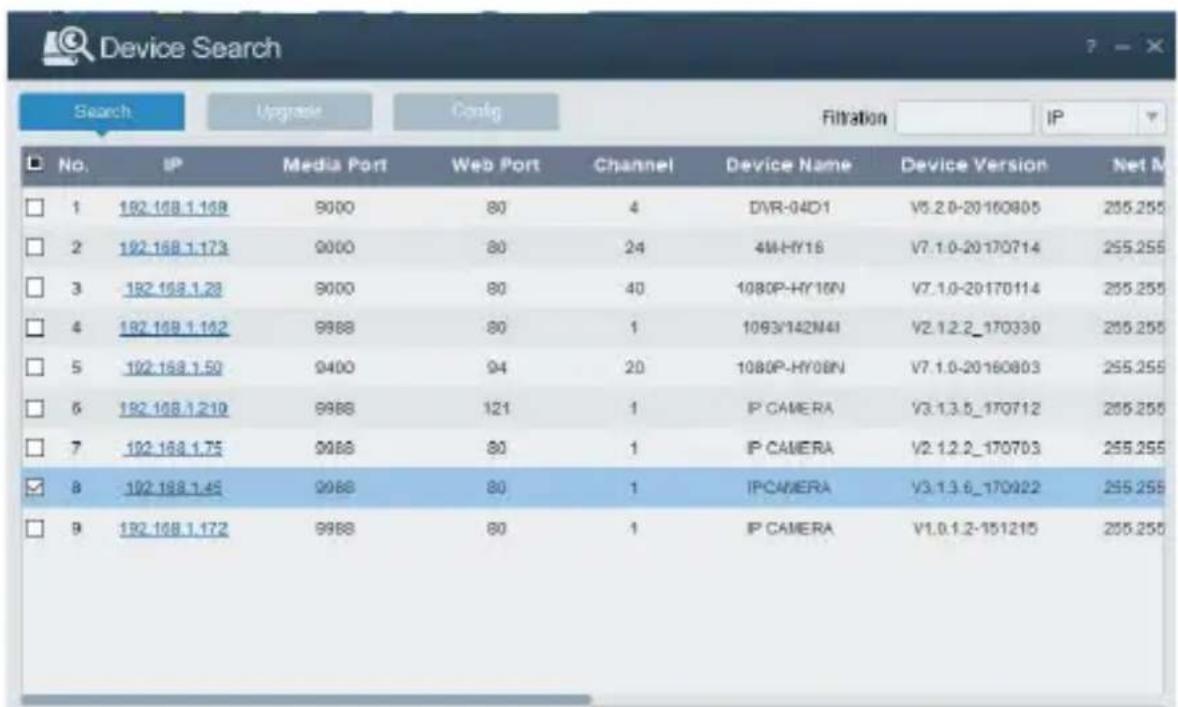
If the searched IP address and PC IP address are not in the same network segment, user may modify IP address, subnet mask, and other parameters of IP camera by using "Device Config. Tool" software.
First select the device to modify IP address and then input new IP address, subnet mask, gateway and username/password. Insert the password and click Modify button to change IP address of the device.

*IMPORTANT NOTE: IP camera Default Settings
Default Static IP Address:192.168.1.168
Username: admin
Password: admin
Media port: 9988
-
Before using IE (Internet Explorer) browser to access the IP camera for the first time, related plug-in components must be installed by following the procedure below:
-
Access IP address of the IP camera for installing plug-in only for the first time. In the Web Page opened select "Download", after that select "Run" in the pop-up below
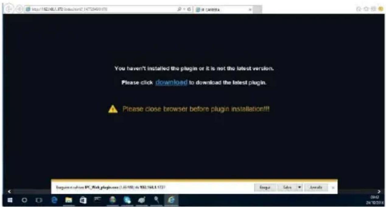
- Wait for plug-in download, after that confirm the ActiveX Installation.
- Select "Install" and wait for the installation is completed.
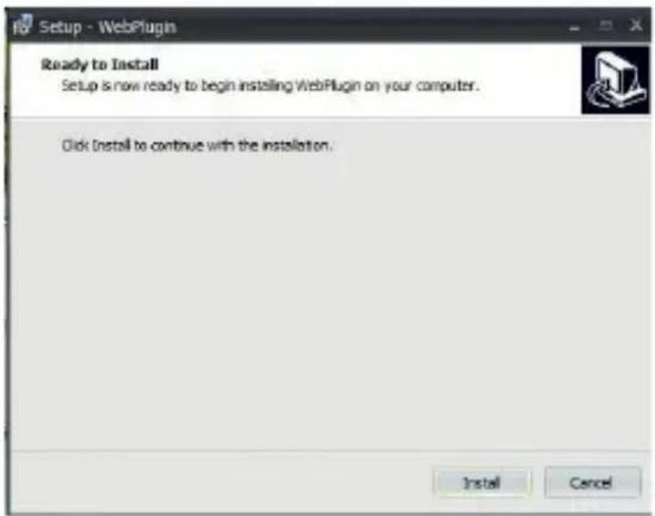
- After completed the Active X installation, close the Internet Explorer Web Page and launch it again, put the IP Camera Address and the Login screen will be displayed. SelectUsername (default:admin), a Password (default:admin) and Language.
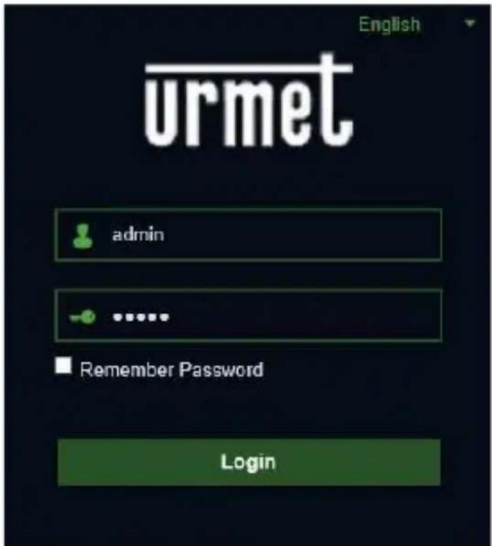
- Select "Login" in order to enter in LIVE screen.
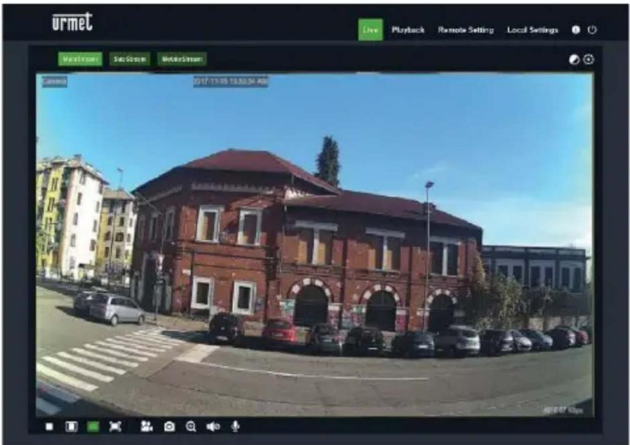
- Click the buttons on the top left corner in the Web Page to select the stream to display (Main Stream, Sub Stream or Mobile Stream)
PTZ CONTROL
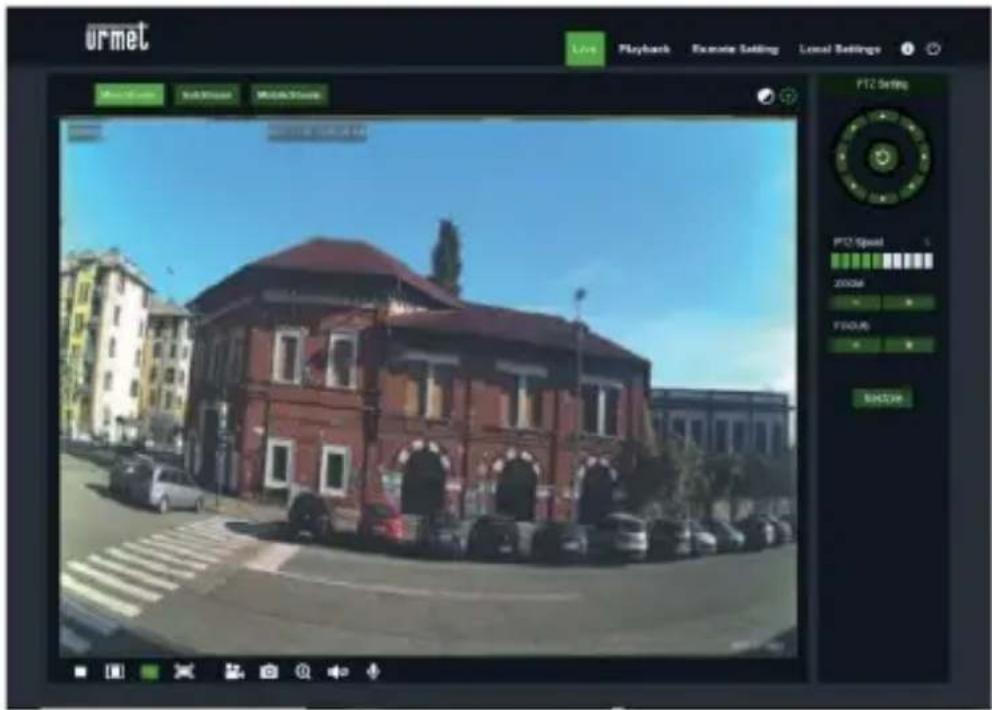
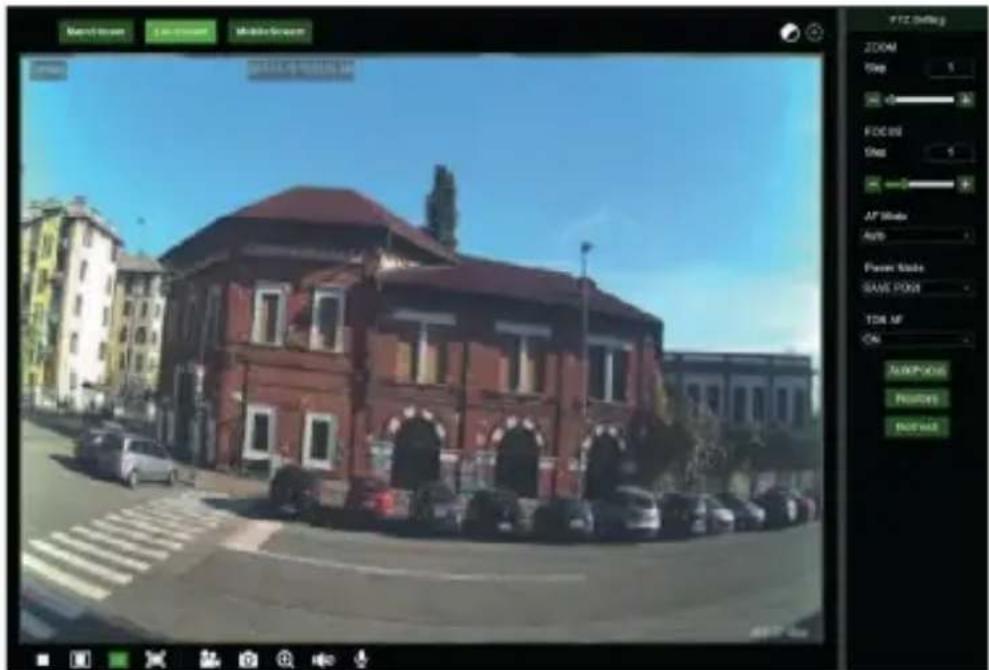

(PTZ control) select the icon to open the following window:
On Autofocus cameras with AF optics, the PTZ interface will be as follows:
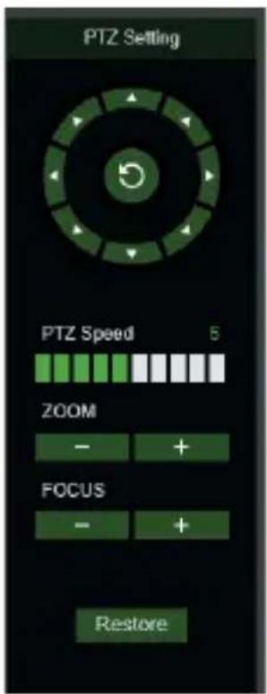
Eight different angles can be selected on the circular control:
- PTZ Speed: 0 - 10 indicates different PTZ speeds.
- ZOOM zooms in and out.
FOCUS increases or decreases FOCUS - Restore resets default settings.
On Auto Focus cameras with DF optics, the PTZ interface will be as
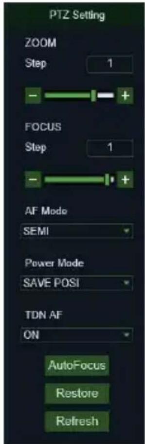
follows:
| Option | Value | Explanation |
| Zoom | Step/-/+ | Manually adjusts zoom (+ zoom in / - zoom out) Step: defines zooming speed |
| Focus | Step/-/+ | Manually adjusts focus (+ increase / - decrease) Step: defines focusing speed |
| AF MODE | SEMI + AUTO + MANUAL + OFF | This function is used to customise the camera focusing mode. Possible options are: SEMI: focusing is performed only after the zooming operations are finished. AUTO: focusing is adjusted automatically. MANUAL: focusing is adjusted manually. OFF: focusing and zoom are deactivated. Activate this option after having adjusted focus and zoom as required |
| ONE SHOT AF | / | Function not available. |
| TDN AF | ON + OFF | This function, when activate, allows automatic focus adjustment at each day -> night or night -> day switch. |
| LENS INIT | / | This re-initialises the optics and obtained optical calibration. To be performed when the camera is installed for the first time and in case of movements with consequent change of the framed picture. IMPORTANT: do not use with AF MODE equal to OFF |
| POWER MODE | SAVE POSI + OFF + WIDE | This is used to adjust the zoom whenever the camera is switched back on. SAVE POSI: this holds the zoom position set before the camera was switched off. OFF: do not save the settings stored before switch-off. WIDE: the camera is switched on in Wide mode. |
| AutoFocus | / | Adjusts focus automatically |
| Restore | / | Resetset PTZ interface default settings (including focus) |
| Refresh | / | Updates the PTZ interface with changes to parameters (including focus) |
MOTION ALARM MANAGEMENT
The camera is capable of generating alarms when it detects movements.
It is possible to enable this function, in the Remote Setting, within the Alarm Motion menu
PIR ALARM MANAGEMENT
The camera is equipped with an infrared (PIR) sensor capable of generating presence detection alarms.
To enable and configure this function, select the AlarmPIR menu in the Remote Setting
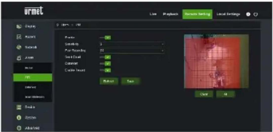
The configuration parameters are as follows:
- Enable: allows you to enable detection using the PIR sensor
Sensitivity: establishes the sensitivity of the alarm detection
Post Recording: establishes the number of seconds of recording
Send Email: establishes whether to send an email in case of alarm
Deterrent: establishes whether to activate the deterrent actions - Enable record: establishes and enables video recording
DETERRENCE FUNCTION CHECK (only for model 1099/208)
This function allows the camera to emit visual and audible signals in the event of an alarm.
To enable and configure this function, select the Alarm> Deterrence menu in the Remote Setting
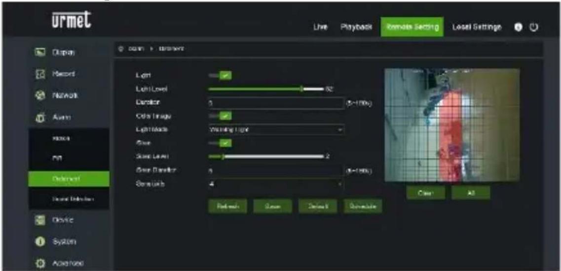
The configuration parameters are as follows:
Light: allows you to enable the alarm light emission
Light Level: establishes the light intensity value of the flash
Duration: establishes the duration of the light signal
Color image: establishes whether the image examined to generate the alarm is in color or in black / white
Light Mode: establishes the type of light emission, fixed or stroboscopic
Siren: allows you to enable the alarm sound emission
Siren Level: establishes the sound intensity value of the signal
Siren Duration: : establishes the duration of the sound signal
Sensitivity: : establishes the sensitivity of the alarm detection
SOUND ALARM MANAGEMENT
The camera is equipped with a microphone capable of generating alarms in the presence of noises.
To enable and configure this function, select the Alarm Sound Detection menu in the Remote Setting
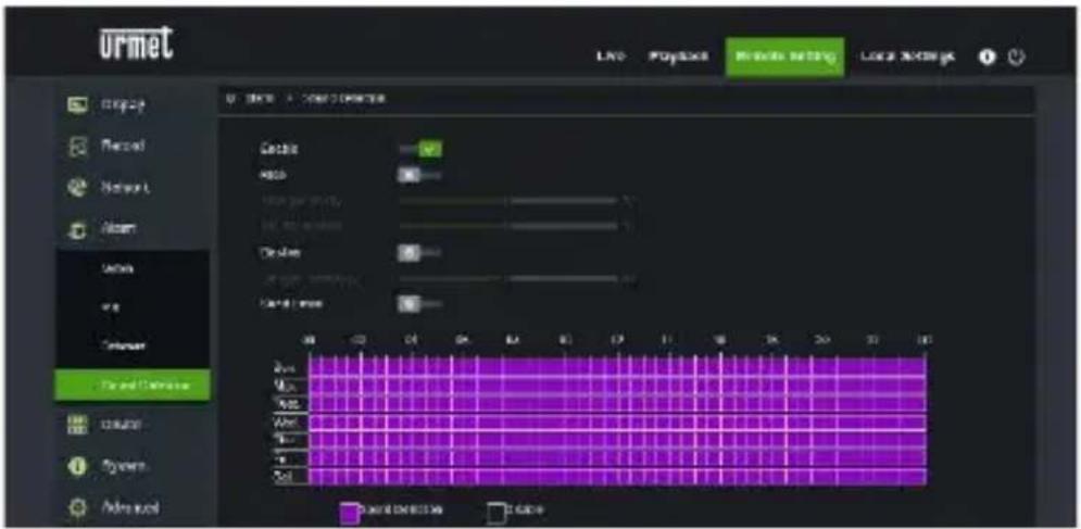
The configuration parameters are as follows:
- Enable: allows you to enable noise detection
- Rise: establishes that the alarm is generated with a sound of increasing intensity
- Decline: establishes that the alarm is generated with a sound of decreasing intensity
- Send Email: determines whether to send an email in the event of an alarm
Finally, the scheduler allows you to enable detection based on time schedule
Mobile software
Mobile Software is used for the iOS (iPhone, iPad) and Android platforms (Android Smartphone, Tablet). The following is a description of the Mobile Client Software.
SMARTPHONE DEVICE
Uromet iUVS plus Mobile Software
Uromet iUVS plus is a TVCC application for iOS and Android on smartphones, pads and tablets that is compatible with all URMET devices, both IPCam (CodecH265) and DVR/NVR/HVR (all codecs).
iUVS Plus can be downloaded from Play Store to the following link:
iUVS Plus can be downloaded from Apple Store to the following link:
Main features:
- Multichannel audio/video live streaming
- Multichannel remote playback
Double stream playback - Fisheye Camera support in Live and Playback modes
Alarm notifications - Custom single video stream configuration
Video signal format management 4:3-16:9 - Local playback
- Video signal in portrait or landscape mode
Device list export function - Image sharing on social media/remote drives and personal clouds
- PTZ
- Image and Video capture
Multi-device support
IMPORTANT NOTE
For more details about how to use the App and the features description please refer to the IP Camera user manual or online support available in UmetiUVS Plus.
CORRECT DISPOSAL OF THIS PRODUCT
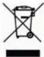
DIRECTIVE 2012/19/EU OF THE EUROPEAN PARLIAMENT AND OF THE COUNCIL of 4 July 2012 on waste electrical and electronic equipment (WEEE) The symbol of the crossed-out wheeled bin on the product or on its packaging indicates that this product must not be disposed of with
your other household waste.
Instead, it is your responsibility to dispose of your waste equipment by handing it over to a designated collection point for the recycling of waste electrical and electronic equipment.
The separate collection and recycling of your waste equipment at the time of disposal will help to conserve natural resources and ensure that it is recycled in a manner that protects human health and the environment.
For more information about where you can drop off your waste equipment for recycling, please contact your local city office, your household waste disposal service or the shop where you purchased the product

The updated version of this quick start guide, the complete manual, the software and firmware of the devices are available for download at www.urmet.com. Open the page dedicated to the product by scanning the QR code below with your smartphone and then select the section DOCUMENTATION AND RESOURCES.
Guide rapide
H.265 IP CAMERA SERIES
INDICE
INDICE 50
Generalites 51
AVERTISSEMENTS 51
Installation 54
INSTALLATION BULLET CAMERA 54
INSTALLATION MINI DOME CAMERA 57
INSTALLATIONCAMERAMINIDOME 58
INSTALLATION VANDAL-PROOF DOME CAMERA 60
Configurations IP de l'unite de filmage 61
Nutzername (UserName): admin
Password (Password): admin
Media Port: 9988
For assistance and information about Umet products and systems you can scan this QR code with your smartphone or visit
www.urmet.com >> Contacts >> Export Sales Network
Umet S.pA. reserves the right to make changes to its products at any time, without prior notice.
Released in July 2019.
www.urmet.com | info@urmet.com
All Uromet products bear the markC E
Made in China to Umet specifications.
urmet
urmet