Eagle Tempo - Coffee machine Victoria Arduino - Free user manual and instructions
Find the device manual for free Eagle Tempo Victoria Arduino in PDF.


User questions about Eagle Tempo Victoria Arduino
0 question about this device. Answer the ones you know or ask your own.
Ask a new question about this device
Download the instructions for your Coffee machine in PDF format for free! Find your manual Eagle Tempo - Victoria Arduino and take your electronic device back in hand. On this page are published all the documents necessary for the use of your device. Eagle Tempo by Victoria Arduino.
USER MANUAL Eagle Tempo Victoria Arduino
text_image
Victoria ArduinoINSPIRED BY YOUR PASSION.
natural_image
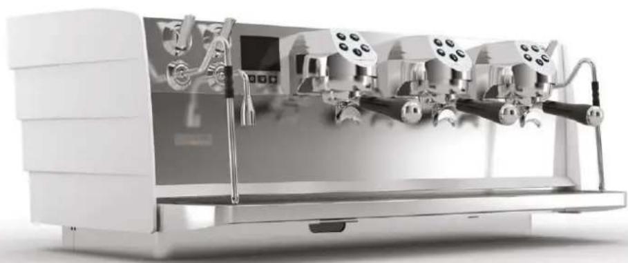
Exterior view of a modern espresso machine with three main levers (no visible text or labels)EAGLE TEMPO

natural_image
Simple beige V-shaped graphic with a central V-shaped notch, no text or symbols present.EN USER HANDBOOK (Translation of the Original Instructions)
FR MANUEL D'INSTRUCTIONS (Traduction des Instructions Originales)
natural_image
Symbol of a light bulb inside a black circle (no text or numbers present)text_image
Safety warning illustration showing a yellow warning sign with an exclamation mark and a cross symbol over a snowy landscape.text_image
Prohibition sign with crossed-out trash bin and no text or symbolstext_image
Safety warning illustration showing a person using a tool to lock a device with warning symbols and hazard signstext_image
Safety warning illustration showing hazard symbols and a cross symbol over a landscape with mountains, trees, and a warning sign.EN SAFETY INDICATIONS
- The present manual is an integral and essential part of the product and is to be delivered to the user. Carefully read all warnings in the manual as they provide important information required to install, use and maintain the coffee machine safely. Keep this manual in a safe place for further consultation.
- This coffee machine must only be used for the purposes described in the present manual. The manufacturer cannot be held responsible for any damages caused by improper, mistaken and unreasonable use.
- Before using the machine, read this manual in its entirety or, at the very least, read the safety and set up instructions.
- This appliance can be used by children aged from 8 years and above and persons with reduced physical, sensory or mental capabilities or lack of experience and knowledge if they have been given supervision or instruction concerning use of the appliance in a safe way and understand the hazards involved. Children must not play with the appliance. Cleaning and maintenance must not be carried out by children unless supervised.
• After having removed the packaging, make certain that the coffee machine is not damaged in any way. If you have any doubts, do not use the coffee machine and contact a professionally qualified person. Always keep all packaging (plastic bags, polystyrene foam, nails, etc.) out of the reach of children as they are a potential source of danger and never loiter the environment with such materials. - The machine can be used with ground coffee only.
- The coffee machine can be installed only in places where the use and maintenance is limited to trained personnel.
- The access to the service area is restricted to persons having knowledge and practical experience of the appliance, in particular as far as safety and hygiene are concerned.
- The machine must be installed on a horizontal surface at appropriate height so that the top of the machine is higher than 1.2 m.
- The appliance must not be installed where it may be used water jets.
• The noise level of the machine is less than 70db(A). - To facilitate aeration of the coffee machine, position the aeration portion of the machine 15 cm from walls or other machinery.
- Remember that to install, maintain, unload and regulate the coffee machine, the qualified operator must always wear work gloves and safety shoes.
- Before turning ON the coffee machine make certain that the rating indicated on the label matches the available power supply. The nameplate can be seen inside the machine when removing the water collection tray. The machine must be installed according to the applicable federal, state and local standards (codes) in force with regard to plumbing systems including back-flow prevention devices. For this reason, the plumbing connections must be carried out by a qualified technician. The warranty expires if the characteristics of the power supply do not correspond to the nameplate data.
- When installing the coffee machine, it is necessary to use the parts and materials supplied with the machine itself. Should it be necessary to use other parts, the installation engineer needs to check
their suitability for use in contact with water for human consumption. The installer must Make the hydraulic connections respecting the rules of hygiene and water safety to environmental protection in force in the place of installation. So for the hydraulic plant contact an authorized technician. Always utilise the new hose supplied for connection to the water supply. Old hoses must not be utilised.
- On installation, the qualified electrician must fit a circuit breaker switch as foreseen by the safety norms in force that has a contact open distance that permits the complete disconnection under conditions of overload category III, which must be installed in the power supply system in accordance with the wiring regulations. For the Australian and New Zealand markets, the disconnector must be installed in accordance with AS/NZS 3000.
- In case of installation in kitchens, connect the equipotential conductor to the terminal on the machine indicated by the symbol .

natural_image
Pure electrical circuit symbol for a lamp, no text or numbers present- It is advisable to install a mains earth leakage circuit breaker with a rated differential current not exceeding 30mA.
- The manufacturer cannot be held responsible for any damages incurred if the system is not grounded. For electrical safety, this machine requires a ground system. Contact a technically certified electrician who must check that the line electrical capacity is adequate for the maximum capacity indicated on the coffee machine label.
- There are some basic rules for the use of any electrical appliance. In particular:
- Never touch the coffee machine with wet hands or feet;
- Never use the coffee machine with bare feet;
- Never use extension cords in areas equipped with baths or showers;
- Never pull on the power supply cord to unplug the coffee machine;
- Never leave the coffee machine exposed to atmospheric agents (rain, direct sunlight, etc..);
- Never let children, unauthorized personnel or anyone who has not read this manual operate the coffee machine.
- The qualified electrician must also check that the section of the installation's cables is large enough for the absorbed power of the appliance.
- Never use adapters, multiple jacks or extension cords. When such items prove absolutely necessary, call in a qualified electrician.
- To prevent dangerous overheating, it is advisable to fully extend the power supply cord. Never block the intake and/or heat dissipation grills, in particular those for the cup warmer.
- The user must never replace the coffee machine's power supply cord. If this cord is damaged, turn OFF the coffee machine and have it replaced by a professionally qualified technician.
- Should it be necessary to replace the power cord, this replacement operation must only be performed by an authorized service centre or by the manufacturer.
- The coffee machine needs to be supplied with water that is suitable for human consumption and compliant with the regulations in force in the place of installation. The installation engineer needs
confirmation from the owner / manager of the system that the water complies with the requirements and standards stated above.
- For machines connected to the mains water supply, the minimum pressure must be 0.2 MPa (2 bar) and the maximum pressure for correct machine operation must not exceed 0.65 MPa (6,5 bar).
- The operating temperature must be within the range of [+5, +25]^ . In case of prolonged storage at a temperature below 2^ , empty the machine hydraulic system to prevent it from freezing. In case of freezing, do not switch the machine on before having reconditioned it for at least 1 hour at a suitable room temperature.
-
At the end of installation, the coffee machine is switched ON and taken to rated operating conditions, leaving it in a state in which it is “ready for operation”. After reaching the “ready for operation” condition, the following dispensing operations are carried out:
-
Dispense water from each group for at least 10 seconds;
- Dispense water from the hot water wand for at least 10 seconds;
- Empty the steam boiler completely. Repeat the whole operation at least 3 times.
At the end of installation, it is good practice to draw up a report of the operations.
- It is forbidden to leave the machine switched ON without the presence and surveillance of a qualified operator. Simonelli Group is not responsible for damages caused by failure to comply with this prohibition.
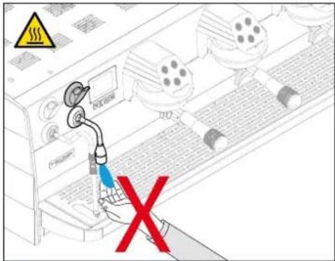
- Be extremely careful when using the steam nozzle. Never place your hands under the nozzle and never touch it right after use.
• Before cleaning the coffee machine follow the instructions given in this manual carefully. - Once started the washing machine, do not interrupt, the detergent residue may remain inside the dispensing group.
- In case of breakdown or poor function, turn OFF the coffee machine. Never tamper with the machine. Contact only professionally qualified personnel. Only the manufacturer or an authorized service center can make repairs and only using original spare parts. Non compliance with the above can compromise machine safety.
- In case of fire, disconnect power to the machine by turning off the main switch. Its absolutely avoid to extinguish the fire with water while power to the machine is on.
- When the machine is left unattended for a long period, close the water inlet tap.
- New hose set supplied with the appliance is to be used and that old set should not be reused.
- Before performing any sort of maintenance, the authorized technician must turn OFF the coffee machine and disconnect the power cable.
text_image
Safety warning sign with warning triangle, cross symbol, and warning symbols over landscape background- Should you decide to stop using this type of machine, we suggest you render it inoperable by unplugging it and cutting the power supply cord.
- Never dispose of the machine in the environment: to dispose of the machine, contact an authorized center or contact the manufacturer for pertinent indications.
INFORMATION TO THE USERS
natural_image
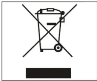
Symbol of a trash bin crossed with two crossed lines, no text or labels presentUnder the senses of the Directives 2015/863/EU concerning the reduction of the use of dangerous substances in electric and electronic equipment, as well as the disposal of wastes.
The symbol of the crossed large rubbish container that is present on the machine points out that the product at the end of its life cycle must be collected separately from the other wastes. The user for this reason will have to give the equipment that got to its life cycle to the suitable separate waste collection centres of electronic and electro-technical wastes, or to give it back to the seller or dealer when
buying a new equipment of equivalent type, in terms of one to one.
The suitable separate waste collection for the following sending of the disused equipment to recycling, the dealing or handling and compatible environment disposal contributes to avoid possible negative effects on the environment and on the people's health and helps the recycling of the materials the machine is composed of. The user's illegal disposal of the product implies the application of administrative fines as stated in Law Decree n.22/1997" (article 50 and followings of the Law Decree n.22/1997).
PREPARATION BY THE PURCHASER
Preparation of the installation site
The purchaser must prepare the surface on which the machine will stand suitable to support the machine weight (see the installation chapter).
Electrical requirements
The mains power installation must comply with the safely regulations and standards in force in the country of installation and must include an efficient earth system. An omnipolar cut-off device must be installed on the power line upstream of the machine.


The power wires must be sized according to the maximum current required by the machine to ensure a total voltage loss under full load of less than 2%.
Plumbing requirements
Prepare a suitable drain and a mains that supply water a maximum hardness of 5/6 French Degrees (50/60 ppm).
SYMBOLS

A

B

C

D

E
A General hazard
B Electrical shock hazard
C Burns hazard
D Hazard of damage to the machine
E Operation reserved for the qualified technician, in compliance with current standards
RESIDUAL RISKS
Although the manufacturer has provided mechanical and electrical safety systems, dangerous areas persist during the use of the machine:

• Coffee dispensing groups.
- Steam wand.
- Hot water wand.
- Cup warmer.
MACHINE RECEIVING
TRANSPORT
text_image
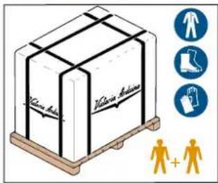
Klaus Aisha Klaus Aisha Human + HumanThe machine is transported on pallets containing several machines inside cartons strapped to the pallet.
Operators performing any shipping or handling operations must wear gloves, safety shoes and overalls with elasticized cuffs.
The machine must be moved by 2 or more operators.

Failure to respect current safety regulations and standards on lifting and handling materials absolves the Manufacturer from all liability for possible damage to person or things.
MOVEMENTS
text_image
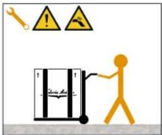
Safety warning illustration showing a person using a tool to lock a device with warning symbols and hazard signs- Slowly lift the pallet about 30 cm from the ground and reach the loading area.
• After checking that there are no obstacles, things or people, proceed with the loading.
- Once you arrive at your destination, always with a suitable lifting device (e.g. forklift), after making sure that there are no things or people in the unloading area, take the pallet to the ground and move it about 30 cm from the ground, until to the storage area.
STORED
text_image
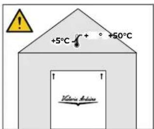
+5°C +50°C Victoria MedicineThe package containing the machine must be stored away from atmospheric agents.
Before performing the following operations, make certain that the load is in stable and will not fall when the straps are cut.
Wearing gloves and safety shoes, the operator must cut the straps and store the product. During this operation, see the product technical features for the weight of the machine being stored and proceed as necessary.
UNPACKING
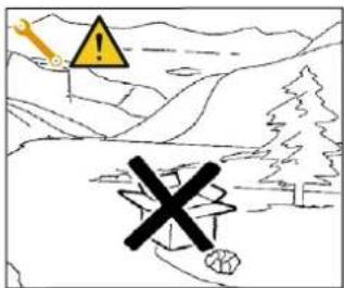
text_image
Safety warning illustration showing a warning sign with an exclamation mark and a warning light symbol above a landscape background.Once the machine has been released from the pallet or container, do not pollute the environment with these items.
CONTENTS CHECK
Upon receipt of the box, check that the packaging is intact and visually undamaged. Inside the packaging must be the instruction manual and the relative kit.
In case of damage or faults, contact your local dealer.
For any communication, always communicate the serial number.
The communication must be carried out within 8 days from the receipt of the machine.
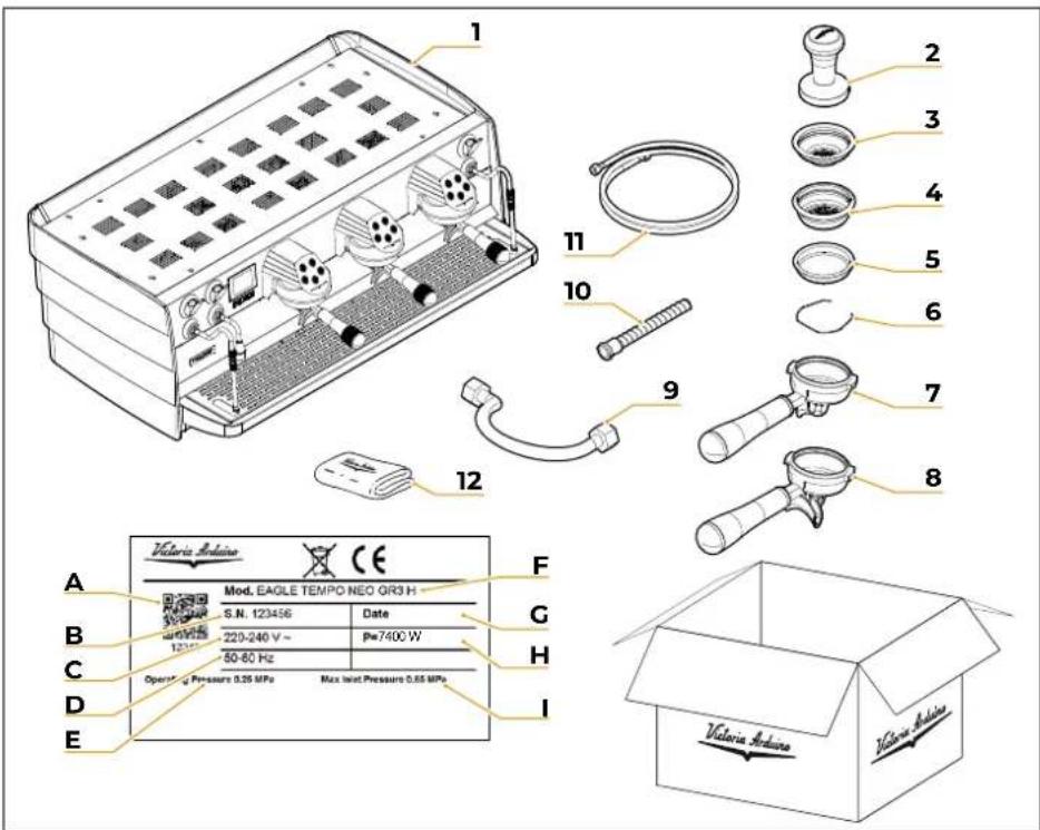
text_image
Victoria Edoine Mod. EAGLE TEMPO NEO QR3 H S.N. 123456 Date 220-240 V ~ Pw7400 W 50-60 Hz Operating Pressure 0.25 MPa Max Inlet Pressure 0.65 MPa Victoria Edoine A B C D E F G H I 2 3 4 5 6 7 8 9 10 11 121 Machine (example image)
2 Coffee tamper
3 Single filter
4 Double filter
5 Blind filter
6 Spring
7 Filter holder single coffee
8 Filter holder double coffee
9 Filling tube (L = 500 mm)
10 Draining pipe
11 Filling tube (L = 1500 mm)
12 Microfibre cloth
A QR Code
B Serial number
C Power supply
D Frequency
E Water main operating pressure
F Model and version
G Production date
H Power
Water main max pressure
FR PRESCRIPTIONS DE SÉCURITÉ
natural_image
Pure electrical circuit symbol for a lamp, no text or labels presenttext_image
Safety warning illustration showing a hazard symbol with an exclamation mark and warning sign, set against a landscape background.natural_image
Symbol of a trash bin crossed with two crossed lines, no text or labels presenttext_image
Safety warning illustration showing a person using a tool to lock a device with warning symbols and hazard signstext_image
Safety warning illustration showing hazard symbol with warning sign and cross symbol over landscapeCongratulations for purchasing a Victoria Arduino machine!
Read this booklet carefully to "prepare" your in the best possible way.
Thanks to the intelligence and practicality of this machine, you'll realise how easy it is to prepare excellent espressos and creamy cappuccinos. In time, you will also realise how efficient the new technologies we have developed are and how little maintenance is required.
Thank you for the preference.
With best wishes,
SIMONELLI | GROUP
FR
MACHINE À CAFÉ MODÈLE: EAGLE TEMPO NEO / DIGIT
2
DATI TECNICI
TECHNICAL DATA
DONNÉES TECHNIQUES
| ModelloModelModelé | NEO DIGIT | ||||
| GruppiGroupsGroupes | 2 | 3 | 2 | 3 | |
| VoltaggioVoltageVoltage | V | 220-240 / 380-415 | |||
| PotenzaPowerPuissance | W | 6000 7 | 400 4700 | 5200 | |
| Potenza con scaldatazzePower with cup warmerPuissance avec chauffe-tasse | W | 6400 7 | 900 5100 | 5700 | |
| Capacità caldaia vaporeSteam boiler capacityCapacité chaudière vapeur | I | 8 | 11 | 7 | |
| Capacità caldaia caffè (ciascuna)Coffee boiler capacity (each one)Capacité chaudière café (chacun) | I | 0,14 | / | ||
| Peso nettoNet weightPoids net | kg(lb) | 62(136,69) | 73(160,94) | 64(141,09) | 79(174,16) |
| Peso lordoGross weightPoids brut | kg(lb) | 79(174,17) | 96(211,64) | 84(185,19) | 102(224.87) |
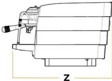
| DimensioniDimensionsDimensions | Xmm(inch) | 825(32,5) | 1055(41,5) | 825(32,5) | 1055(41,5) |
| Y 416 (16,4) | |||||
| Z 650 (25,6) | |||||
natural_image
Technical line drawing of a mechanical device with no visible text or symbols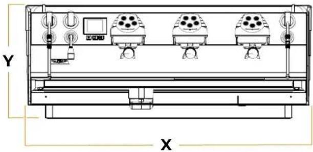
natural_image
Technical line drawing of a rectangular industrial or exhibition setup with four rows of lighting fixtures and control panels (no text or symbols)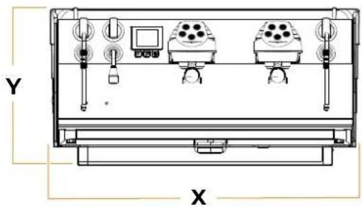
natural_image
Technical line drawing of a device chassis with labeled X and Y axes (no text or symbols on components)3
text_image
Technical diagram of a portable air purifier with numbered components and a digital display showing A.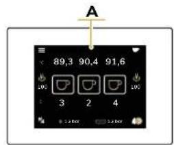
text_image
A 89,3 90,4 91,6 100 3 2 4 5:24:00 12:00:00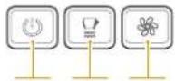
BCD
text_image
E I F H GIT
EN
FR
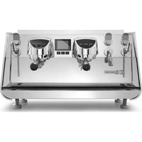
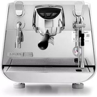
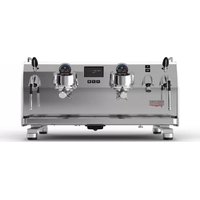
EAGLE TEMPO is a solid and compact intelligent professional coffee machine, suitable for all those who dedicate their lives to coffee.
1 Cup warmer surface
2 Right steam knob
3 Right steam wand / EasyCream 2
4 Filter holder
5 Cup grid
6 Water collecting dray
7 Hot water wand
8 Left steam wand / EasyCream 1
9 Left steam knob
10 Hot water knob
A Display
B Machine ON/OFF
C Cup warmer ON/OFF
D Cleaning
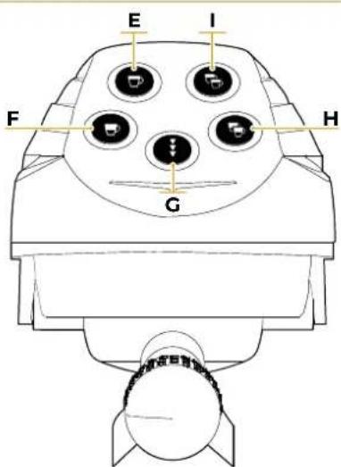
E Single long coffee button
F Single short coffee button
G Continuous coffee dispensing button
H Double short coffee button
Double long coffee button
A Écranw
B Machine ON/OFF
C Chauffe-tasses ON/OFF
D Lavage
E Touche simple café longue
F Touche simple café court
G Touche de distribution café en continu
H Touche double café longue
1 Touche double café court
IT
3.1
USO PREVISTO
- Machine designed and built respecting what is expressed in the declaration of conformity.
- It must be used by professionals in the sector for the supply of coffee, water and steam.
- The machine can only be used with ground coffee.
- An area for the preheating of the cups has been provided. Only for this use must be used, any other use is to be considered improper use and therefore dangerous.
FR
3.1
USAGE PRÉVU
This chapter lists a number of reasonably foreseeable improper uses.
The machine must, however, always be used in respect of the instructions given in this manual.
- Use by non-professional operators.
- Introduction of liquids other than softened drinking water with a maximum hardness of 5/6 French degrees (50/60 ppm).
- Touching the delivery areas with the hands.
- Introduction, into the filter holder, ground different than coffee.
- Placing objects other than cups on the cup warmer.
• Heating drinks or other non-food substances.
• Covering the cup warmer with cloths. - Obstructing the vents with cloths or other items.
• Using the machine if wet.
3.2
USAGE NON CONFORME
text_image
Victoria ArduinoIT
text_image
150 mm +5 +30°C >900mmEN
FR
To lift the machine are necessary 2 or more operators.
Before installing the machine, make sure the area where it will be installed is compatible for the size and weight of the machine.
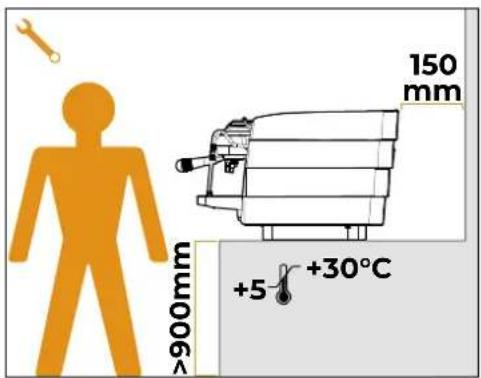
- Position the machine on a horizontal plane at least 900 mm high from the ground.
- Keep at least 150 mm around the machine for proper ventilation.
4.1
POSITIONNEMENT
text_image
Technical diagram of a water treatment or gas handling system with labeled components and directional arrows indicating flow.IT
EN
FR
4.2
4.2
4.2
Avoid throttling in the connecting tubes. Assess that the drain pipe is able to eliminate waste. It is forbidden to use connecting pipes already used in the past. Filter maintenance is the responsibility of the purchaser.


1 Mesh filter
2 Softener
3 Drain ∅ 50 mm
Prior to connecting the machine to the electrical mains, assess that the voltage shown on the machine's data plate corresponds with that of the mains.
text_image
60" 10" 10" 10" 10" 60" x 3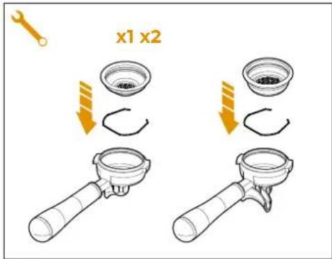
text_image
x1 x2IT
4.4
OPERAZIONI PRELIMINARI
At the end of installation, the machine is Switched ON and taken to rated operating conditions, leaving it in a state in which it is "ready for operation".
After reaching the "ready for operation" condition, the following dispensing operations are carried out:
- Dispense water from each group for at least 10 seconds;
- Dispense water from the hot water wand for at least 10 seconds;
- Empty the steam boiler completely by opening the steam wands for 1 minute.
Repeat the whole operation at least 3 times. At the end of installation, it is good practice to draw up a report of the operations.
4.5
PREPARING
THE ACCESSORIES
- Insert the ring inside the filter holder, in the space provided.
- Insert the single filter into the single coffee filter holder.
- Insert the double filter into the double coffee filter holder.
FR
4.4
OPÉRATIONS PRÉLIMINAIRE
natural_image
Illustration of a mechanical assembly with tools and components, no visible text or symbolsIT

The operations described below must be carried out only by specialized technicians.

The Manufacturer is not responsible for any damage to things or persons deriving from a failure to comply with the above.
FR

HOT WATER ECONOMISER ADJUSTMENT

Operation carried out whit the machine turned ON.
5.1
RÉGLAGE ÉCONOMISEUR EAU CHAUDE

Act with a screwdriver on the screw located at the top of the machine:
- Turn the adjustment screw CLOCKWISE to INCREASE the temperature of the hot water.
- Turn the adjustment screw ANTICLOCK-WISE to DECREASE the temperature of the hot water.
All models EAGLE TEMPO are equipped with a level gauge to keep the water level inside the boiler constant.
At the first start, the machine automatically loads water for 90 seconds, at the end of which it stops if it has reached the level.
If the machine still requires water, the continuous/stop buttons flash. Simply restart the machine to complete filling.
At the end of the installation, the qualified technician must provide the total replacement of the water contained in the boiler for at least three times before using effectively the machine.
text_image
Technical diagram showing a control panel with labeled components and directional arrows, likely illustrating a system or process flow.IT
Pressure switch setting
To adjust the service pressure of the boiler, thus regulating the water temperature, according to the various requirements or features of the coffee used, adjust the pressure gauge from the display on the page "Temperatures / Steam boiler settings". See the relevant paragraph for further information.
Recommended value: 1 - 1,4 bar (according to the type of coffee).
FR
5.3
RÉGLAGE
PRESSOSTAT / POMPE
Pump pressure setting
To adjust the pump pressure, use the setting knob A underneath the machine:
• INCREASE (clockwise).
- DECREASE (counter-clockwise).
Recommended value: 9 bar.
text_image
Diagram illustrating a mechanical assembly or inspection process with three identical views of a device and a highlighted orange box labeled '一' (one) being pointed to a tool.IT

text_image
EAGLE TEMPO 4"EN

Before starting to use the appliance, the operator must be sure to have read and understood the safety prescriptions contained in this booklet.
FR

All EAGLE TEMPO models have the power button at the bottom on the right-hand side. The button has two states:
- 0 = machine OFF;
- I = machine ON.
After performing the operations described in chapters 4 and 5, to switch the machine ON, press the power button to the 'I' position. The display will show the welcome page with the EAGLE TEMPO for 10 seconds.
With the machine in power, keep the switching on button pressed for 4 seconds to let the machine start.
If the self-diagnostics reports anomalies or failures, the operator MUST NOT intervene. Please contact the Service Centre.
6.1
ALLUMAGE ET
REMLISSAGE CHAUDIÈRE
text_image
Diagram illustrating a medical or laboratory procedure with labeled components and warning symbols, including a hand holding a device and a magnified inset showing a device with multiple pins.EN
For electronic card maintenance, turn the machine off by means of the external main switch or disconnect the plug.
FR
The water filling of the boiler starts automatically.
When the level is reached, the display indicates the start of heating.
When the display shows the main screen, the water is at temperature.
After water filling:
- Press a dispensing button until water flows out of the group.
- Dispense steam for a few seconds using the steam wand.
The preparation of the machine is finished and it is ready for use.
For an optimal result it is necessary for the machine to reach temperature in all its parts, the time required varies between 15 and 20 minutes from switching ON.
In case of pauses of more than 8 hours it is advisable to change the water.
The machine is equipped with an electronic autolevel, so it automatically restores the water in the boiler.
text_image
Diagram showing two cartoon characters interacting with a device, with upward arrows indicating flow or movement in a process.FR
6.2 EROGAZIONE CAFFÈ ESPRESSO
1 Select the desired filter holder (single or double coffee).
2 Fill with ground coffee up to the maximum level indicated by the line inside the filter.
3 Press the coffee in the filter uniformly using the appropriate tamper.
4 Clean the edge of the filter of coffee residues.
Before insert the filter holder, the group must be purged for at least 2 seconds to refresh the water present in the circuit, turning ON and OFF the supply.
5 Insert the filter holder in the dispensing group and turn it to fix it, as indicated by the arrows.
6.2 DISTRIBUTION CAFÉ ESPRESSO
natural_image
Illustration of two cartoon characters with pigtails standing on a patterned surface, surrounded by industrial equipment (no text or symbols)IT
6 Place the cups, or the cup, in the case of a single filter holder, correctly under the spouts.
FR
If pre-infusion is enabled in the selected recipe, the machine dispenses water for a time set by the operator (ON time), stops for a time set by the operator (OFF time), and then resumes dispensing until the end.
7 When the previously set quantity is reached, the pump switches off and dispensing ends automatically.
At the end of each coffee dispensing leave the filter holder inserted in the group so that it will keep warm for a successful delivery.
It will also prevent the head gasket inside the group head premature drying out.
text_image
Diagram showing three identical devices with circular components mounted on a rack, with a hand holding a red X symbol indicating no protection or damage.IT
text_image
Diagram showing three industrial equipment units with circular components and a hand holding a valve, indicating a process or inspection setup.EN
text_image
Diagram illustrating a mechanical testing setup with three identical devices and a labeled component 'A' using a tool.FR
6.3
EROGAZIONE VAPORE

While using the steam nozzle, you must pay attention to not place your hands beneath it or touch just after it has been used.
6.3
DISTRIBUTION VAPEUR

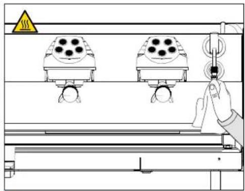
Before use the steam wand, cleaning out of the condensation for at least 2 seconds. Before and after use, clean the steam wand with a cloth moistened with warm water.
The two steam nozzles are articulated to guarantee their easy use.
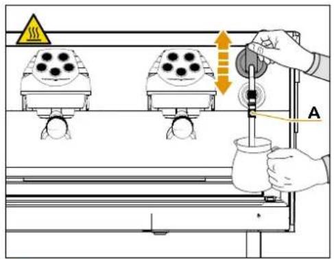
To use the steam:
1 Make certain that the spout of the nozzle is within the grill.
2 Raise or lower the knob.
3 When steam comes out, move the nozzle using the rubber protection A.
text_image
Technical diagram showing three identical mechanical components mounted on a platform with a hand adjusting one component, accompanied by a warning symbol and safety warning triangle.IT
6.4
PREPARAZIONE
DEL CAPPUCCINO
text_image
Diagram illustrating a coffee machine setup with warning symbols and a 1/3 speed indicator, showing components like a pitcher, feeding rod, and coffee cups.EN
6.4
MAKING
CAPPUCCINO
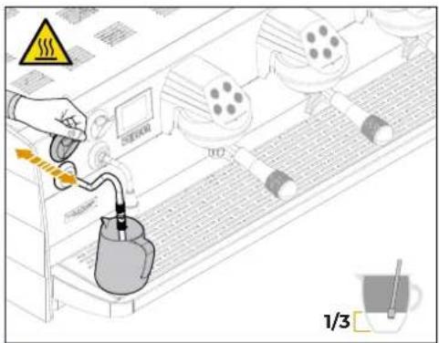
Before use the steam wand, cleaning out of the condensation for at least 2 seconds to remove any possible dirt.
Clean the steam wand with a cloth moistened with warm water.
Fill a stainless steel container, preferably a truncated cone shape, 1/3 full with cold milk.
Sample servings:
- 250 ml = single cappuccino
. 500 ml = double cappuccino
There are 3 steps to frothing milk.
1 Stretch:
To increase the volume of milk to 1/2 of the container, you must introduce air into it.
Immerse the steam wand while keeping the nozzle just below the surface of the milk and dispense steam using the knob.
FR
6.4
PRÉPARATION
DU CAPPUCCINO
- 500 ml = cappuccino double
natural_image
Illustration of a pitcher with a tool inside, showing liquid being poured into it (no text or symbols)EN
text_image
3 3/4 60 65°CFR
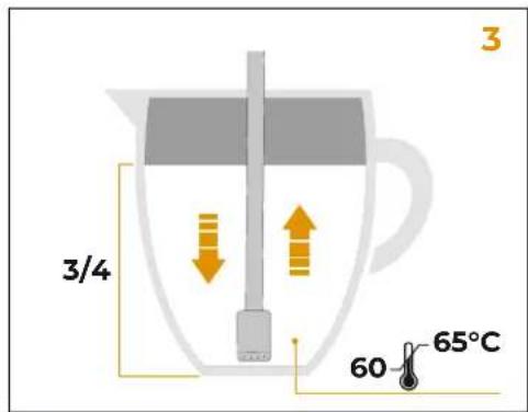
While the milk is being whipped, a gurgling sound will be heard and bubbles will be visible on the surface.
Keep the container stationary to avoid large bubbles and always keep the nozzle just below the surface of the milk.
Place the steam wand on one side of the container. This creates a vortex inside the milk which keeps it well mixed and reduces any bubbles.
2 Tournoyer:
When the volume of whipped milk has reached 3/4 of the container and the temperature has reached 60-65°C, turn OFF the steam by leaving the knob. It is necessary at this stage to be able to move the wand vertically until it touches the bottom of the container for no more than a couple of seconds.
3 Réchauffer:
text_image
Diagram showing a hand operating a control panel with three-mounted devices and warning symbols, likely illustrating a safety or industrial process.IT
natural_image
Illustration of a coffee cup pouring liquid into a container with a lid, showing a plus sign (no text or symbols)EN
FR
If there are large bubbles on the surface after whipping, knock gently on the outside of the bowl to remove them.
If there are still some bubbles, skim the top a couple of millimetres with a spoon.
Remove the steam wand and swirl the container to give the whipped milk a glossy shine.
The milk is ready to be served.
Do not delay the service or the mounting will lose its density.
When finished, purge the steam wand to remove milk residues and clean it thoroughly with a cloth moistened with hot water.
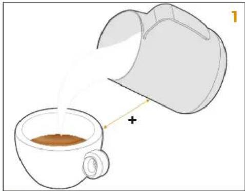
1 Start by gently pouring the heated milk into the centre of the coffee cup, ensuring that the coffee cream remains intact
6.5.1
ÉMULSION DU LAIT
natural_image
Illustration of a coffee cup and its open lid, showing a drop in the cup (no text or symbols)IT
natural_image
Illustration of a coffee cup and its open lid with orange arrows indicating flow or transformation (no text or symbols)EN
2 When the coffee and milk are well combined and the volume in the cup is about half full, speed up the pouring process by bringing the spout of the container closer to the cup and increasing the pouring angle.
3 Keep the container as close as possible to the surface of the cup. Shake the container from side to side to release the heavier milk into the cup. This is how you create shapes and patterns in the cup.
text_image
Safety warning diagram showing a hand holding a device with a blue cable and red X mark, indicating no readable text or symbols.FR
While using the hot water nozzle, pay careful attention not to place your hands beneath it or touch it just after it has been used.
The use of the hot water wand must always be preceded by the purge of the hydraulic circuit for at least 2 seconds.
Place a suitable container under the hot water nozzle.
6.5
DISTRIBUTION
EAU CHAUDE
text_image
Diagram showing a hand using a spray gun to interact with a device, labeled with parts 1 and 2, and warning symbol.IT
Pull the knob towards the front (DOWN) or push it towards the back (UP) to dispense hot water.
1 UP: Hot water dispensing dose 1
2 DOWN: Hot water dispensing dose 2
Wait for the end of the programmed dispensing or return the lever to its central rest position.
FR
Hot water can be delivered at the same time as coffee.
See chapter 7 "PROGRAMMING" for setting the water doses.
As an option, the machine can be fitted with the EasyCream steam wand instead of the standard steam wand.
The automatic steam nozzle can be used to deliver steam to foam milk or heat other liquids.
Place a suitable container with milk or another beverage inside it beneath the automatic steam nozzle.
6.6
LANCE À VAPEUR AVEC SONDE DE TEMPÉRATURE (EASYCREAM - OPTIONNEL)
text_image
Technical diagram showing a hand operating a water tap with warning symbols and warning labels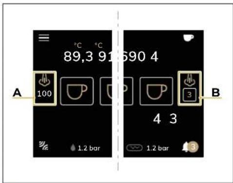
text_image
A 89,3 91 690 4 100 1.2 bar B 4 3 1.2 bar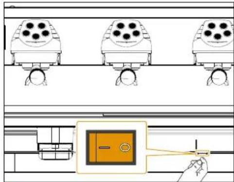
text_image
Diagram showing three rows of identical camera setups with four circular lenses, one highlighted in a box labeled '一' (one) and another pointing to a hand.IT
1 Make certain that the spout of the nozzle is within the grill.
2 Raise or lower the knob.
3 Steam will flow from the wand until the liquid reaches the set temperature.
On the display, according to the CPU settings, the home screen displays two modes:
A STD: Displays the steam temperature and the recipe selection is made from the specific recipe page.
B DIR / DIR (Auto): Displays the recipe number and allows the user to select it directly from here.
See chapter 7 "PROGRAMMING" for setting the EasyCream steam wand.
FR
To switch OFF the machine, press the power switch at the bottom on the right-hand side to the "0" position.
The display, the buttons and the lights will switch OFF.
6.7
ARRÊT DE LA MACHINE
For long pauses and for the safety of people, it is good practice to also disconnect the plug from the mains.
These icons and functions are repeated on display screens.
X To Home Page
Y Save settings
Z Previous page
J Scroll options / decrease
K Scroll options / increment
VISION DES ICONES
text_image
EAGLE TEMPO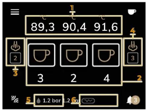
text_image
89,3 90,4 91,6 2 3 2 4 3 5 1.2 bar 1.2 sq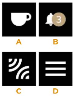
text_image
A B C DIT
7.1
ACCENSIONE DISPLAY
SWITCH ON THE DISPLAY
When Switched ON, the display shows the EAGLE TEMPO logo for 10 seconds.
FR
7.1
ALLUMAGE DE L'ÉCRAN
The Home Page shows:
1 Groups temperature (°C) (NEO only)
2 Dispensing time (s)
3 EasyCream 1 recipe (left-optional)
4 EasyCream 2 recipe (right-optional)
5 Coffee boiler pressure (bar) (NEO only)
6 Steam boiler pressure (bar)
7.2
ÉCRAN D'ACCUEIL
Moreover, the relevant icons allow access to:
A Recipes Menu
B Alarms Menu
C Connectivity Menu
D Main Menu
If there is an EasyCream steam wand (optional) and it is enabled in the "DIR" version, press the numbers below the icon to select the EasyCream recipe.
For more details, see Chapter 14 "DISPLAY PARAMETERS".
text_image
Recipe 1 Coffee Easycream 2


X
IT
7.3
MENU RICETTE
Press A on the Home Page to enter the Recipe Menu.
In this menu, the user can add, modify and/or view the recipes in the machine.
Press an icon to access the specific recipes:
1 Coffee recipes
2 Milk recipes (EasyCream - optional)
If the EasyCream option is not available, only the coffee recipes will be present.
Press X to return to the Home Page.
FR
7.3
MENU RECETTES
text_image
Recipe > Coffee 1 2 3 4 Arabica Custom 1 Custom 2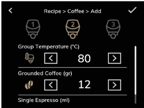
text_image
Recipe > Coffee > Add 1 2 3 Group Temperature (°C) < 80 > Grounded Coffee (gr) < 12 > Single Espresso (ml)IT
7.3.1
RICETTA CAFFÈ
Allows to manage the coffee recipes:
1 Adding a new recipe
2 Select recipe
3 Edit recipe
4 Delete recipe
The selected recipe is highlighted and has a mark in icon 2.
Press 1 to add a new recipe, or 3 to modify an existing recipe and set the parameters for each group with J and K.
If the set doses exceed 500 ml, the display will show the letter "C", which means continuous dose.
FR
7.3.1
RECETTES DE CAFÉ
For more details, see Chapter 14 "DISPLAY PARAMETERS".
To confirm press Y.
To go back press Z.
text_image
Recipe > Easycream 1 2 3 4 Arabica Custom 1 Custom 2
text_image
89,3 89,3 89,3 100 2 2 2 1.2 bar 1.2 barIT
7.3.2
RICETTA LATTE (EASYCREAM)
MILK RECIPE (EASYCREAM)
This function is active only if the optional EasyCream is present.
The management of milk-based recipes depends on the mode setting of the EasyCream: STD, DIR OR DIR (Auto).
For more details, see Chapter 14 'DISPLAY PARAMETERS'.
STD EasyCream:
Allows to manage the milk recipes:
1 Adding a new recipe
2 Select recipe
3 Edit recipe
4 Delete recipe
To select a recipe, press on the name of the recipe.
The selected recipe is highlighted and has a mark in icon 2.
Press 1 to add a new recipe, or 3 to modify an existing recipe and set the parameters with J and K.
For each lever, parameters can be set for the UP and DOWN positions.
To confirm press Y. To go back press Z.
FR
7.3.2
RECETTES DE LAIT (EASYCREAM)
text_image
Recipe > Easycream 1 2 3 Custom 1 Custom 2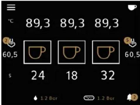
text_image
℃ 89,3 89,3 89,3 60,5 24 18 32 1.2 Bar 1.2 BarIT
EasyCream DIR:
Allows the user to manage milk recipes, numbered from 1 to 6:
1 Add a new recipe
2 Modify the recipe
3 Delete the recipe
If a recipe is deleted, the other recipes scroll down one position, and so they will be associated with a different number.
It is possible to select from 1 to 6 recipes independently between the right and left lever, by pressing the EasyCream icon on the home screen.
The number above the icon indicates the selected recipe.
Press 1 to add a new recipe, or 3 to modify an existing recipe and set the parameters with J and K.
The settable parameters refer only to the lever in the DOWN position.
In this mode, the lever in the UP position has only the purging function.
To confirm press Y.
To go back press Z.
FR
EasyCream DIR:
text_image
Recipe > Easycream 1 2 3 4 Arabica 1 Custom 2 Custom 3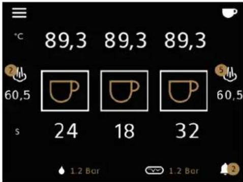
text_image
℃ 89,3 89,3 89,3 60,5 24 18 32 60,5 1.2 Bar 1.2 BarIT
EasyCream DIR (Auto):
Allows the user to manage milk recipes, numbered from 1 to 6:
1 Add a new recipe
2 Select the recipe
3 Modify the recipe
4 Delete the recipe
If a recipe is deleted, the other recipes scroll down one position, and so they will be associated with a different number.
If a default recipe 2 is not selected, recipe no.1 is automatically set as the default.
It is possible to select from 1 to 6 recipes independently between the right and left lever, by pressing the EasyCream icon on the home screen. The number above the icon indicates the selected recipe.
After 10 seconds from the end of the dispensing of a recipe other than the default, the machine automatically returns to the default.
Press 1 to add a new recipe, or 3 to modify an existing recipe and set the parameters with J and K.
The settable parameters refer only to the lever in the DOWN position.
In this mode, the lever in the UP position has only the purging function.
To confirm press Y.
To go back press Z.
FR
EasyCream DIR (Auto):
text_image
< Z ✓ Y 4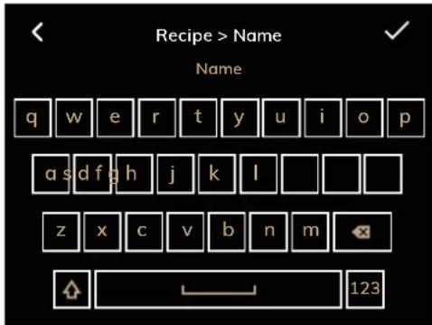
text_image
Recipe > Name Name q w e r t y u i o p a s d f g h j k l z x c v b n m 123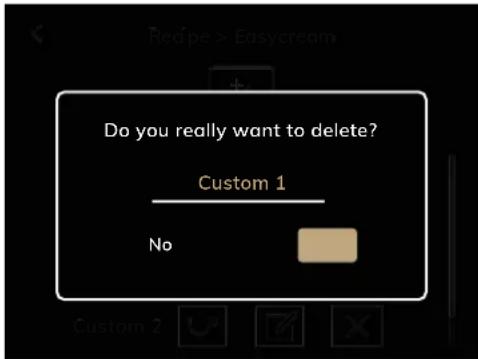
text_image
Do you really want to delete? Custom 1 NoIT
7.3.3
SALVA RICETTA
After setting the recipe parameters and confirming with Y, the recipe name can be entered using the alphanumeric keypad.
Enter the name and press Y to save a new recipe, which will be added to the list.
To go back press Z.
7.3.4
DELETE RECIPE
From the recipe list, press 4 to delete a recipe.
Then press:
- NO: to cancel the deletion.
• YES: to confirm deletion.
FR
7.3.3
SAUVER RECETTE
Press B on the Home Page to access the Alarm Menu, where all errors in the machine are described.
1 Error occurrence date
2 Type of error
3 Error description
4 Error reset
The B icon with the alarm number is only visible if an error is present.
Each number visible in combination with the B icon identifies a specific error.
If there are no active alarms, the B icon will be without a number, but access to the Alarm Menu is still allowed.
After resolving the problem, press 4 to reset the alarm.
To go back press Z.
FR
7.4
MENU ALARMES
text_image
Connectivity 1 Wifi 2 Bluetooth 3 Connections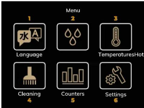
text_image
1 Language 2 Menu 3 TemperaturesHot 4 Cleaning 5 Counters SettingsIT
7.5
MENU CONNESSIONI
Press C on the Home Page to access the Connectivity Menu, which allows to:
1 Connect to WiFi network
2 Bluetooth switch ON
3 Access the connection page of the machine to the grinder (compatible models only)
If an icon is active it turns into golden colour, if not active it is coloured grey.
To go back press Z.
FR
7.5
MENU CONNECTIVITÉ
Press D on the Home Page to enter the Main Menu.
Press the icons to access:
1 Language Setting
2 Hot Water Setting
3 Temperature Setting
4 Cleaning Menu
5 Counters
6 Technical Settings (password required)
7.6
MENU PRINCIPAL
text_image
Language English >


IT
7.6.1
IMPOSTAZIONE LINGUA
Use keys J and K to select the desired display language:
• Italian
- French
- English
• German
- Spanish
- Russian
- Chinese
To go back press Z.
text_image
Hot Water Hot Water Up (s) < Off > Hot Water Down (s)< Off >FR
7.6.1
CONFIGURATION LANGUE
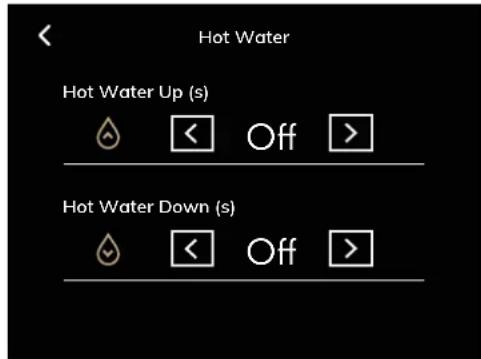
Use keys J and K to set the hot water delivery time:
1 Dispensing time with lever in UP position (s)
2 Dispensing time with lever in DOWN position (s)
The hot water dose can also be set by sampling, carrying out manual dispensing.
7.6.2
For more details, see Chapter 14 "DISPLAY PARAMETERS".
To go back press Z.
Allows setting with the J and K keys:
1 Cup warmer temperature (°C)
2 Steam boiler pressure (bar)
For more details, see Chapter 14 "DISPLAY PARAMETERS".
To go back press Z.
FR
7.6.3
CONFIGURATION TEMPÉRATURES
The Cleaning Menu allows access to:
1 Autopurge
2 Groups cleaning
To go back press Z.
7.6.4
MENU NETTOYAGE
Allows setting with the J and K keys:
1 Enable / disable autopurge
2 Autopurge start delay (s)
3 Autopurge duration (s)
To go back press Z.
The purge function let the groups dispense a small quantity of water to clean themselves before every dispensing.
FR
AUTOPURGE
text_image
Cleaning > Groups Group Washing Cycle 1 < 0 > Group Rinsing Cycle 2 < 4 > Washing Duration (s) 3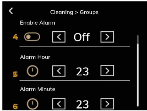
text_image
Cleaning > Groups Enable Alarm 4 << Off > Alarm Hour 5 << 23 > Alarm Minute 6 << 23 >IT
LAVAGGIO GRUPPI
Allows setting with the J and K keys:
1 Group washing cycle
2 Group rinsing cycle
3 Washing duration
FR
LAVAGE DU GROUPES
Moreover, it is possible to programme the appearance of the washing alarm on the display:
4 Enable/disable washing alarm
5 Alarm Hour
6 Alarm Minute
For more details, see Chapter 14 "DISPLAY PARAMETERS".
To go back press Z.
If the alarm is enabled and appears on the display, washing can be started by pressing button D.
During the washing cycle, continuous dispensing button G of the selected group flashes.
text_image
Counters Group 1 1 0 Group 2 2 0 Group 3 3 0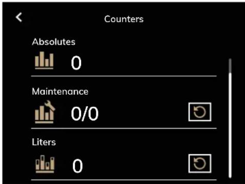
text_image
Counters Absolutes 0 Maintenance 0/0 Liters 0IT
7.6.5
CONTATORI
- Grups 1-2-3 counters: number of coffees dispensed for each group.
- Partial counter: number of coffees dispensed since last reset.
- Absolute counter: absolute number of dispensed beverages from the machine (non-resettable).
- Maintenance counter: number of cycles left before maintenance. When the threshold is reached, the alarm appears on the display. Reset this counter after maintenance.
- Litres counter: number of litres of water consumed. When the set threshold is reached, the alarm appears on the display.
FR
7.6.5
COMPTEURS
Permet de visualiser:
Where present, press R to reset the relevant counter.
To go back press Z.
This section of the touch screen display allows sensitive parameters to be set which, if incorrectly set, could cause the machine to malfunction.
text_image
Settings X Y Z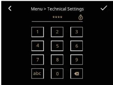
text_image
Menu > Technical Settings **** 1 2 3 4 5 6 7 8 9 abc 0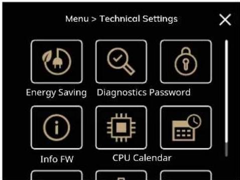
text_image
Menu > Technical Settings Energy Saving Diagnostics Password Info FW CPU CalendarIT
Access to the Technical Settings is possible only after entering the password, which consists of 4 numbers.
FR
The default password for the first login is 1111.
Enter the password using the numeric keypad and press Y to confirm.
After access, it is possible to enter the following menus:
1 Energy Saving
2 Diagnostic
3 Password
4 Info SW
5 CPU configuration
6 Calendar
7 Unit of measure
8 Maintenance
9 Offset
10 Keys and Leds
Press X to return to the Home Page.
text_image
Energy Saving 1 Weekly Program Standby 3 Power Man. Active Groups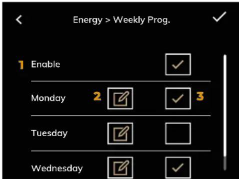
text_image
Energy > Weekly Prog. 1 Enable Monday 2 ✓ 3 Tuesday ✓ ✓ Wednesday ✓ ✓IT
8.1
RISPARMIO ENERGETICO
This menu enables eco-friendly management of machine consumption through the following functions:
1 Weekly Program
2 Standby
3 Power Management
4 Active Groups
To go back press Z.
Press X to return to the Home Page.
FR
8.1
ÉCONOMIE D'ÉNERGIE
This page allows the user to set the rest days and the days in which the machine is scheduled to be automatically turned on and off:
1 Enable or disable the machine's power management function.
2 Adjust the power management settings for the chosen day.
3 Enable or disable power management for the chosen day.
To confirm press Y.
To go back press Z.
8.1.1
PROGRAMMATION HEBDOMADAIRE
The edit screen, using buttons J and K, allows you to set up for the chosen day:
4 Start hour
5 Start minute
6 Stop hour
7 Stop minute
To confirm press Y.
To go back press Z.
FR
text_image
Energy > Standby 1 Enabled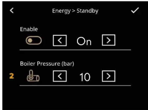
text_image
Energy > Standby Enable Boiler Pressure (bar) 2< 10 >IT
8.1.2
STANDBY
This function allows the user to enter or not enter an active Standby state 1, after a set time of inactivity, which allows the user to choose whether to completely turn off the machine or maintain it at a set pressure (lower than the operating pressure).
If enabled, allows to set with keys J and K, the lowering of steam boiler pressure 2 after 30 minutes of inactivity of the machine.
FR
8.1.2
VEILLE
For more details, see Chapter 14 "DISPLAY PARAMETERS".
To confirm press Y.
To go back press Z.
text_image
Energy > Power Man Enabled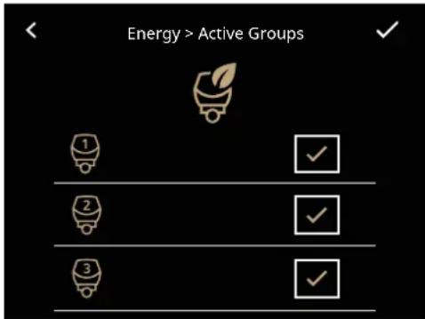
text_image
Energy > Active Groups 1 2 3IT
8.1.3
GESTIONE POTENZA
This function allows the user to activate specific functions for an "eco-friendly" management of the machine's energy consumption.
If enabled, allows the machine's power to be limited to 2500 W.
To go back press Z.
FR
8.1.3
GESTION PUISSANCE
Enables or disables the operation of individual dispensing groups for energy optimisation of the machine.
To confirm press Y.
To go back press Z.
8.1.4
GROUPES ACTIFS
text_image
Diagnostics Cup Warmer Heating Hot Water Valve Pump Enable Boiler Filling Valve Boiler Heating SSR1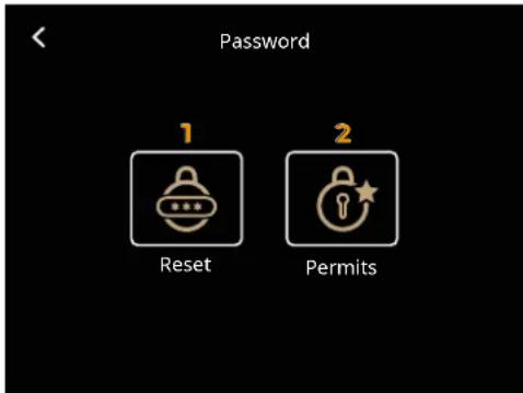
text_image
Password 1 Reset 2 PermitsIT
8.2
DIAGNOSTICA
This menu is used to check the correct functioning of individual machine components.
FR
8.2
DIAGNOSTIC
For more details, see Chapter 14 "DISPLAY PARAMETERS".
To go back press Z.
This menu allows access to:
1 Password reset
2 Permits management
To go back press Z.
8.3
MÔT DE PASSE
Allows to change the password for access to technical settings.
1 Enter the current password and press Y to continue.
For first login, the default password is 1111.
2 Then enter the desired new password and press Y to confirm.
If the password is not correct, the procedure cannot be completed.
To go back press Z.
FR
8.3.1
RÉINITIALISER MOT DE PASSE
text_image
Password > Permits Language ✓ Hot Water ✓ Temperatures ✓ Cleaning ✓
IT
8.3.2
GESTIONE PERMESSI
This screen allows you to choose to which person (user or technician) to assign access permissions to functions.
If the users tries to access a function to which they are not authorised, they will be asked for their password.
To go back press Z.
FR
8.3.2
GESTION AUTORISATIONS
text_image
Info FW 1 Firmware CPU V 1.4 2 Firmware display 12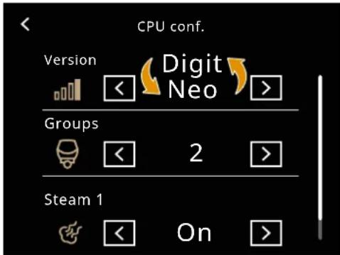
text_image
CPU conf. Version Digit Neo Groups 2 Steam 1 OnIT
8.4
INFO FW
This menu allows you to view:
1 CPU firmware version
2 Display firmware version
Updating the display firmware via the U icon is reserved for the Qualified Technician.
To go back press Z.
FR
8.4
INFO FW
Ce menu affiche:
This menu allows the machine configuration to be changed using keys J and K.
8.5
CONFIGURATION CPU
For more details, see Chapter 14 "DISPLAY PARAMETERS".
To go back press Z.
This menu allows using keys J and K to set the date and time visible on the display:
1 Day
2 Month
3 Year
4 Hour
5 Minute
To confirm press Y.
To go back press Z.
FR
8.6
DATA ET HEURE
This menu allows setting using the keys J and K:
1 Temperature unit (°C/°F)
2 Date format
To go back press Z.
FR
8.7
UNITÉS DE MESURE
This menu allows to select, with keys J and K, the mode in which maintenance is to be called up.
The maintenance alarm can be enabled by setting a maximum number of dispensing cycles, so that when this number is reached, the alarm is activated.
If the number of cycles is set to 0 (zero), a date can be programmed for the activation of the maintenance alarm.
1 Enable/disable alarm
2 Dispensing cycle counter
3 Day
4 Month
5 Year
To go back press Z.
FR
8.8
ENTRETIEN
text_image
Offsets Pump < 0.0 > Steam Boiler < 0.0 > CupwarmerIT
8.9
OFFSET
Offset indicates the difference between a measured value and a reference value.
Temperature probes may differ slightly from an external thermometer.
FR
8.9
OFFSET
We recommend using a Scace and Fluke device for these measurements.
This menu allows the machine offsets to be set using keys J and K.
For more details, see Chapter 14 "DISPLAY PARAMETERS".
To go back press Z.
text_image
Keys and Leds Display Brightness (%) 1 70 Keys Brightness (%) 2 12 Led Bar Enable 3 Off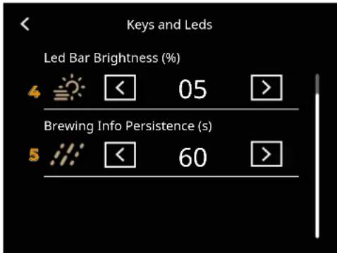
text_image
Keys and Leds Led Bar Brightness (%) 4 < 05 > Brewing Info Persistence (s) 5 < 60 >IT
8.10
TASTI E LED
This menu allows to set, with keys J and K:
[Non-Text]
1 Display Brightness
2 Keys Brightness
3 LED switching ON/OFF
4 Led brightness intensity
5 Persistence of dispensing time on display
To go back press Z.
FR
8.10
TOUCHES ET VOYANTS
Excluding the cleaning of the dispensing group (highlighted on the table below), any cleaning must be carried out with zero energy status (plug disconnected from the mains) and with the hot parts at environment temperature.
FR

Avoid to clean the machine using water jets or standing it in water.
Do not use solvents, chlorine-based products or abrasives.
| Item to be cleaned | After use Daily | Weekly | |
| Steam wand | √ | √ | |
| Filter and filter holder | √ | √ | |
| Body machine | √ | ||
| Cup grid | √ | ||
| Water collection tray | √ | ||
| Dispensing group diffuser | √ | ||
| Dispensing group gasket | √ | ||
| Dispensing group | √ |
FR
natural_image
Technical line drawing of a mechanical assembly with three identical components mounted on a base, no text or symbols present.IT
flowchart
graph TD
    A["Drain with funnel"] --> B["Water supply in beaker"]
    B --> C["Water bath with thermometer"]
    C --> D["Water outlet with + sign"]
    D --> E["Water tap with water level"]
    E --> F["Water outlet with water level"]
EN
FR
9.1
PULIZIA LANCIA VAPORE
Purge the steam wand of any residue and clean it with a cloth moistened with hot water and/or neutral detergent.
If some nozzles remain obstructed after purging, use a paper clip to unblock them.
9.1
NETTOYAGE LANCE VAPEUR
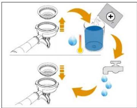
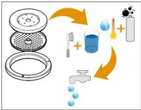
FILTER AND FILTER HOLDER CLEANING
1 Remove the filter from the filter holder, using a tool if necessary.
2 Place the manufacturer's recommended dose of the specific detergent powder in a container with hot water;
3 Put the filters and filter holder (take care not to put the handle in the container) into the container;
4 Wait 30 minutes;
5 Rinse thoroughly with running water; if necessary, clean the filter with a brush.
6 Insert again the filter into the filter holder.
9.2
text_image
Diagram illustrating a scientific apparatus with labeled components and a color-coded legend for chemical reaction or measurement.IT
natural_image
Line drawing of a hand cleaning a device with labeled components (no text or symbols)EN
9.3
PULIZIA CARROZZERIA
Pulizia zona lavoro
BODY MACHINE CLEANING
Work area cleaning
1 Remove the worktop, lifting it up from the front and sliding it out.
2 Remove the water collection dish underneath.
3 Clean everything with hot water and cleansers.
FR
9.3
NETTOYAGE CARROSSERIE
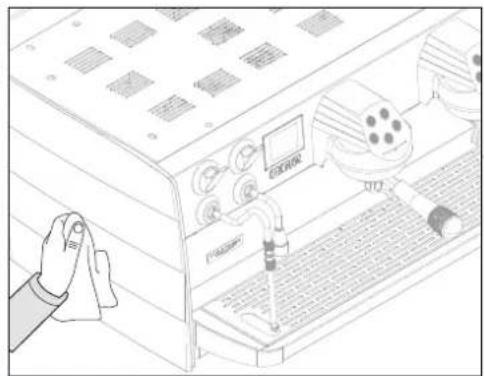
External body cleaning
To clean all external bodies, use a soft cloth moistened with hot water.
Never not use solvents, chlorine-based products and / or abrasives.
Nettoyage carène
natural_image
Illustration of a hand inserting a screw into a rack-mounted device with three rows of circular components (no text or symbols)IT
flowchart
graph TD
    A["Cleaner with lid"] --> B["Reinfection with brush and water bath"]
    B --> C["Water bath + heat source + water displacement"]
    C --> D["Discharge with water drop"]
    D --> E["Water displacement + water displacement"]
    E --> F["Water displacement + water displacement"]
    F --> G["Water displacement + water displacement"]
EN
9.4
PULIZIA
DOCCIA E GUARNIZIONECLEANING
1 Unscrew the screw placed in the centre of the diffuser and shower. Automatically the screw, diffuser and shower fall out.
2 Remove the gasket from the group. If necessary, use a screwdriver with due care not to damage it.
3 Place everything in a container with hot water and specific detergent for about 30 minutes.
4 Brush the shower and the diffuser.
5 Rinse everything thoroughly with running water.
6 Restore everything on the machine by proceeding in the opposite direction to resume normal operation.
FR
9.4
NETTOYAGE DOUCHETTE ET JOINT
text_image
AGLE TEMPO R13 R04 315 3 3 1 "3"IT
EN
FR
9.5
9.5
9.5
PULIZIA GRUPPO
GROUP CLEANING
NETTOYAGE DU GROUPE
Carrying out a washing cycle at least once a day.
With the machine switched ON, a coffee group can be washed by pressing the wash button for 3 seconds.
The continuous dose button for each group starts flashing. If pressed, washing starts for that group.
1 Insert the blind filter into the filter holder.
2 Insert the dose recommended by the manufacturer of the specific powder detergent into the blind filter.
3 Restore the filter holder in the dispensing group.
4 Press the continuous dose button of a group to start the washing cycle.
5 At the end of the washing cycle, the continuous dose button on the group in question starts flashing again to allow the rinsing cycle to begin.
6 Remove the detergent from the filter and press the continuous dose button to start the group rinsing.
7 At the end, restore normal operation of the machine.
When the automatic washing cycle is started, it cannot be interrupted before its end.
If the machine is stopped before the cycle has finished, it automatically resumes the rinsing cycle when it is switched ON again.
In the event of maintenance, switch OFF the machine using the switch and unplug the power cord.
During maintenance / repairs, the parts used must be able to guarantee compliance with the safety and hygiene requirements envisaged for the machine. Original replacement parts can offer this guarantee.
After the repair or replacement of any components of parts that come into contact with food or water, it is necessary to carry out the washing procedure as described in this manual or according to the manufacturer's instructions.
If the machine has been in use recently, wait for it to cool down before carrying out any kind of work on it.
Maintenance includes annual replacement of the group shower and gasket.
To carry out this operation, contact a qualified technician.
Failure to comply with these conditions will automatically invalidate the warranty.
For any additional work on the machine, please contact the dealer where you purchased the product.
If the machine must be shipped:
- Empty the water tank.
- Switch OFF the machine.
- Use the original packaging.
- Give your contact details or put them inside the box.
FR
text_image
Diagram showing a hand pressing down on a device with labeled buttons and a digital display showing icons and numbers.IT
10.1 CAMBIO DELL'ACQUA IN CALDAIA
It is necessary to change the water in the boiler daily at the end of its use, in order to always have the best quality water available.
Simply operate repeatedly with the hot water lever until at least one third of the total litres in the boiler have been extracted.
FR
10.1 CHANGER L'EAU DE LA CHAUDIÈRE
At the beginning of each day's activity and in any case if there are breaks of more than 8 hours, it is necessary to change 100% of the water contained in the circuits using the appropriate dispensers.
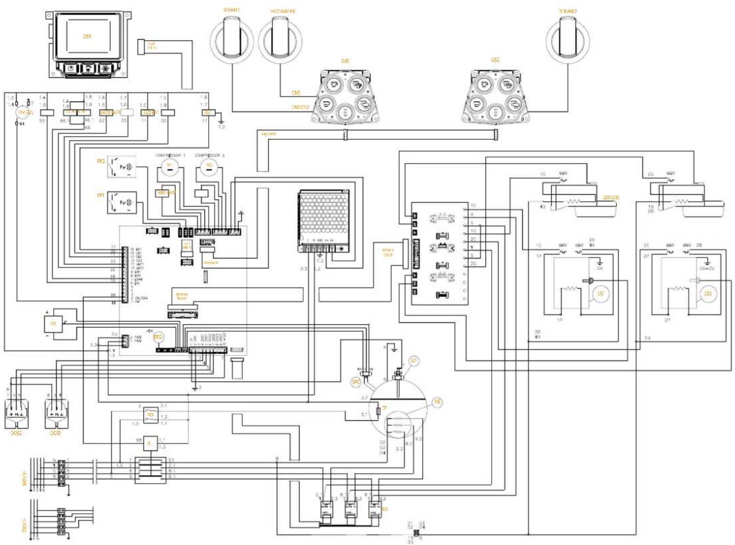
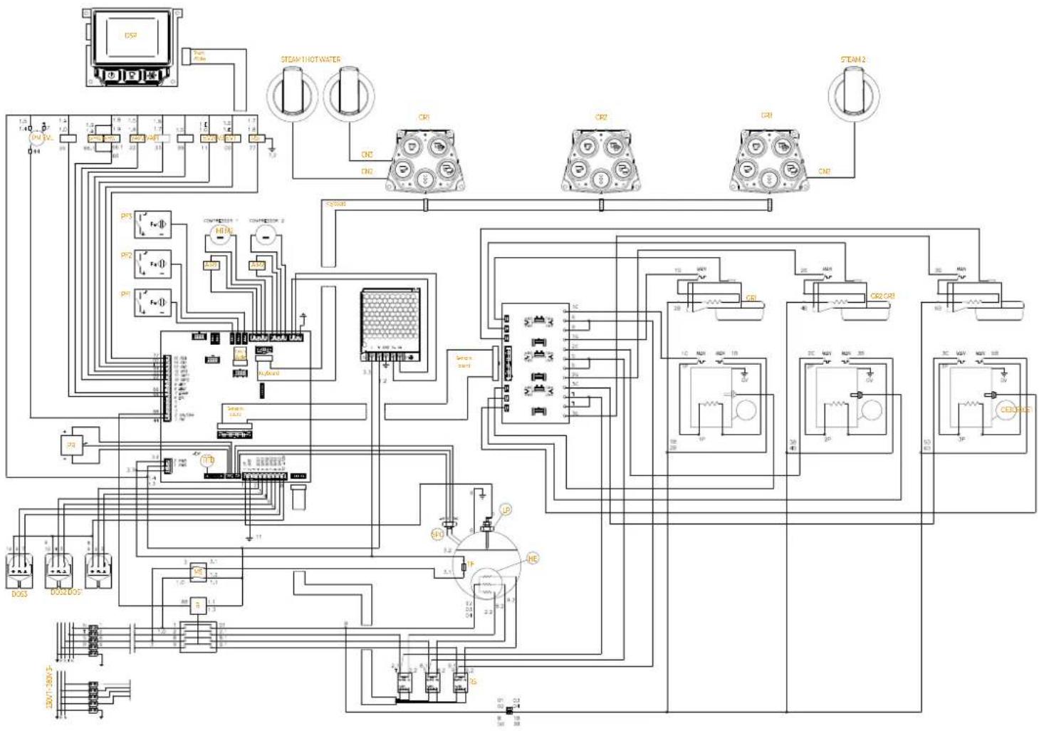
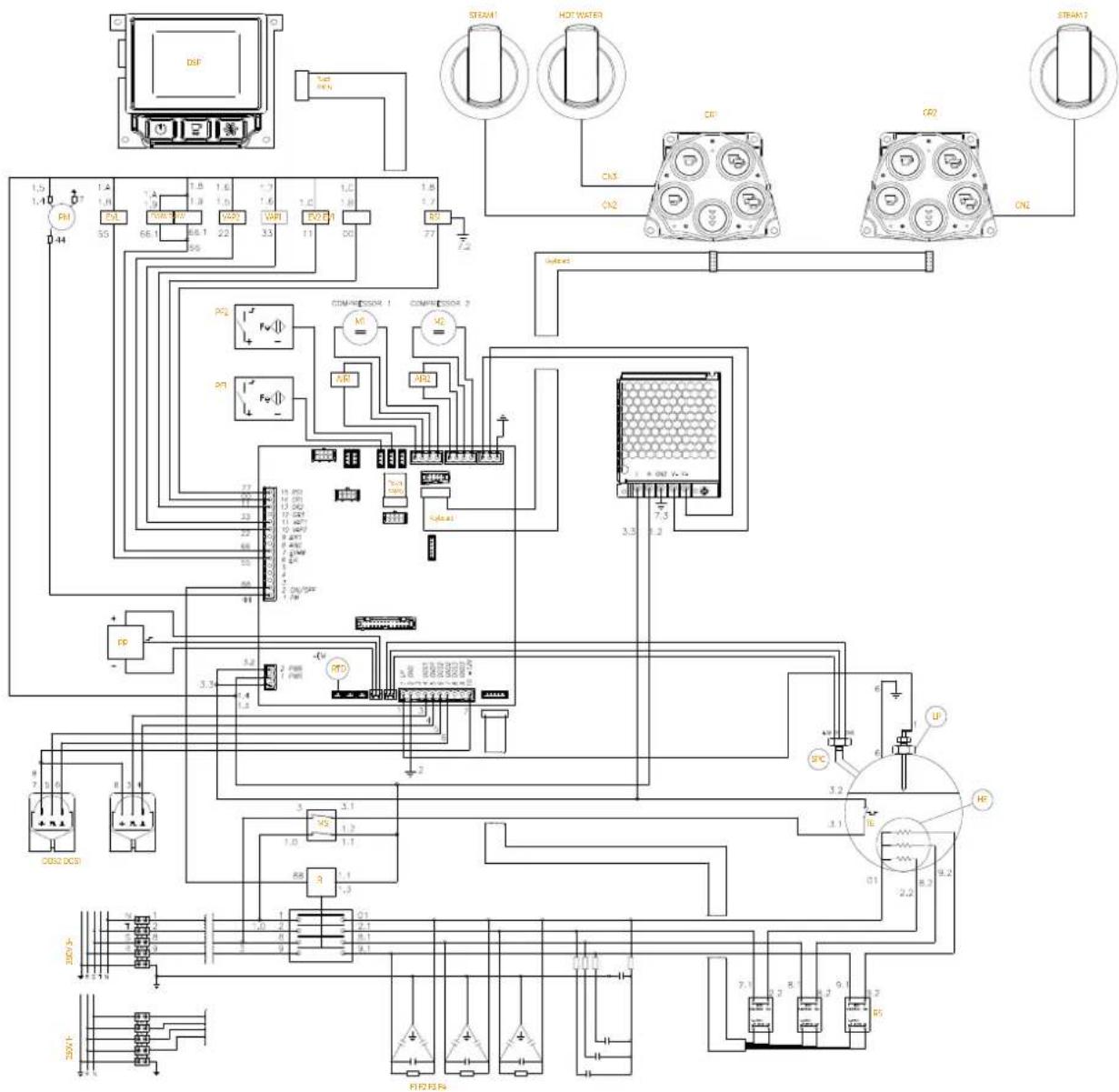
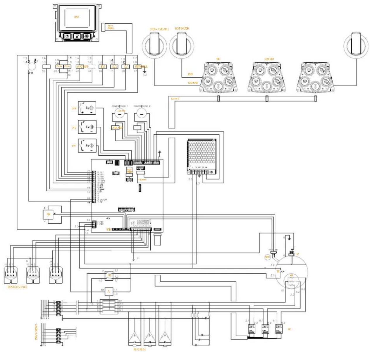
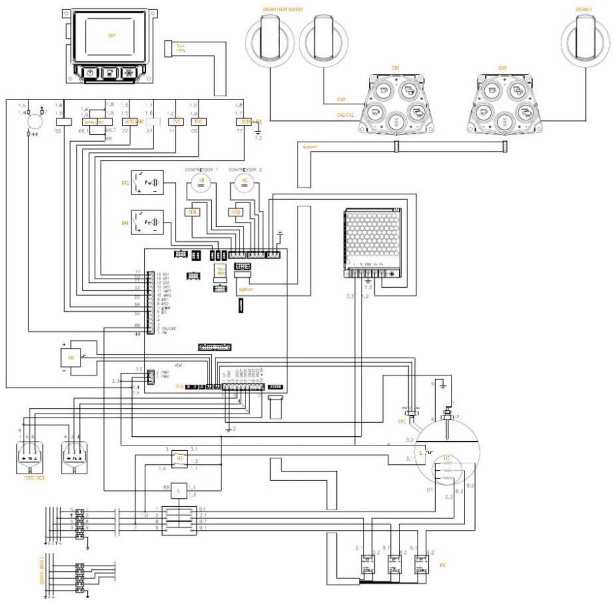
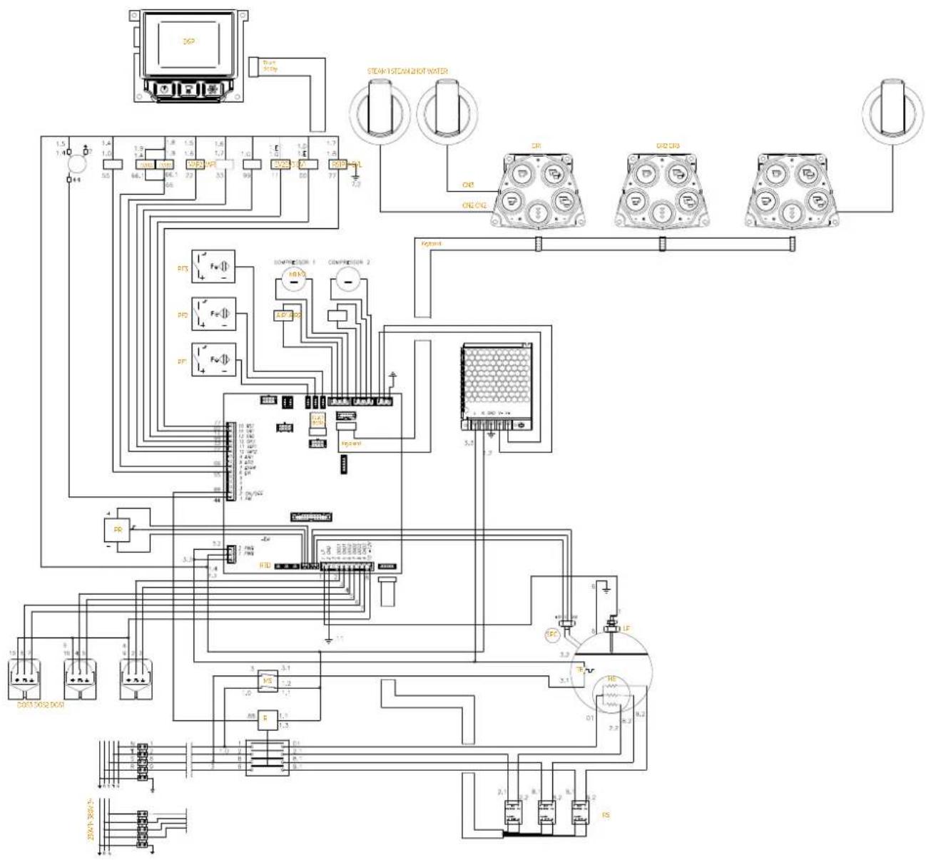
EVHW Hot water solenoid valve
EV1-2-3 Group dispensing solenoid valve
PM Pump motor
R Relay
EVL Level solenoid valve
LP Level probe
SPC Boiler pressure sensor
VAP1-2 Steam solenoid valve
TF Thermal fuse
TE Thermostat
PR Pressure switch
DOS1-2-3 Flow meter
F1-2-3-4 Fuses
RTD Resistive sensor
M1-2 Compressor
GR1-2-3 Dispensing group
DSP Touch Screen Display
HOT WATER Hot water wand
STEAM1-2 Steam wand
HE Steam boiler heating element
MS Main switch
CE1-2-3 Coffee boiler
AIR1-2 Air solenoid valve
RS1 Cup warmer heating element
RS Static relay
PF1-2-3 Filter holder sensor
CN1-2-3 Connectors
FR
LÉGENDE SCHÉMAS ÉLECTRIQUES
flowchart
graph TD
    A[" DSP "] --> B[" Steam1 "]
    A --> C[" HOT WATER "]
    A --> D[" CE CRIGR1 "]
    A --> E[" Steam2 "]
    B --> F[" Control Unit 1 "]
    C --> G[" Control Unit 2 "]
    D --> H[" Control Unit 3 "]
    E --> I[" Control Unit 4 "]
    F --> J[" Control Unit 5 "]
    G --> K[" Control Unit 6 "]
    H --> L[" Control Unit 7 "]
    I --> M[" Control Unit 8 "]
    J --> N[" Control Unit 9 "]
    K --> O[" Control Unit 10 "]
    L --> P[" Control Unit 11 "]
    M --> Q[" Control Unit 12 "]
    N --> R[" Control Unit 13 "]
    O --> S[" Control Unit 14 "]
    P --> T[" Control Unit 15 "]
    Q --> U[" Control Unit 16 "]
    R --> V[" Control Unit 17 "]
    S --> W[" Control Unit 18 "]
    T --> X[" Control Unit 19 "]
    U --> Y[" Control Unit 20 "]
    V --> Z[" Control Unit 21 "]
    W --> AA[" Control Unit 22 "]
    X --> AB[" Control Unit 23 "]
    Y --> AC[" Control Unit 24 "]
    Z --> AD[" Control Unit 25 "]
    AA --> AE[" Control Unit 26 "]
    AB --> AF[" Control Unit 27 "]
    AC --> AG[" Control Unit 28 "]
    AD --> AH[" Control Unit 29 "]
    AE --> AI[" Control Unit 30 "]
    AF --> AJ[" Control Unit 31 "]
    AG --> AK[" Control Unit 32 "]
    AH --> AL[" Control Unit 33 "]
    AI --> AM[" Control Unit 34 "]
    AJ --> AN[" Control Unit 35 "]
    AK --> AO[" Control Unit 36 "]
    AL --> AP[" Control Unit 37 "]
    AM --> AQ[" Control Unit 38 "]
    AN --> AR[" Control Unit 39 "]
    AO --> AS[" Control Unit 40 "]
    AP --> AT[" Control Unit 41 "]
    AQ --> AU[" Control Unit 42 "]
    AR --> AV[" Control Unit 43 "]
    AS --> AW[" Control Unit 44 "]
    AT --> AX[" Control Unit 45 "]
    AU --> AY[" Control Unit 46 "]
    AV --> AZ[" Control Unit 47 "]
    AW --> BA[" Control Unit 48 "]
    AX --> BB[" Control Unit 49 "]
    AY --> BC[" Control Unit 50 "]
    AZ --> BD[" Control Unit 51 "]
    BA --> BE[" Control Unit 52 "]
    BB --> BF[" Control Unit 53 "]
    BC --> BG[" Control Unit 54 "]
    BD --> BH[" Control Unit 55 "]
    BE --> BI[" Control Unit 56 "]
    BC --> BJ[" Control Unit 57 "]
    BD --> BK[" Control Unit 58 "]
    BE --> BL[" Control Unit 59 "]
    BC --> BM[" Control Unit 60 "]
    BD --> BN[" Control Unit 61 "]
    BE --> BO[" Control Unit 62 "]
    BC --> BP[" Control Unit 63 "]
    BD --> BQ[" Control Unit 64 "]
    BE --> BR[" Control Unit 65 "]
II.3 SCHEMA ELETTRICO (NEO - 2 gruppi - ETL)
II.3 ELECTRICAL DIAGRAM (NEO - 2 groups - ETL)
II.3 SCHÉMA ÉLECTRIQUE (NEO - 2 groupes - ETL)
text_image
Electrical schematic diagram with labeled components including resistors, capacitors, relays, and switchesII.4 SCHEMA ELETTRICO (NEO - 3 gruppi - ETL)
II.4 ELECTRICAL DIAGRAM (NEO - 3 groups - ETL)
II.4 SCHÉMA ÉLECTRIQUE (NEO - 3 groupes - ETL)
flowchart
graph TD
    A["DSP"] --> B["STEAM1/NOTWATER"]
    B --> C["CR1"]
    B --> D["CR2"]
    B --> E["CR3"]
    B --> F["STEAM2"]
    C --> G["CR1"]
    D --> H["CR2"]
    E --> I["CR3"]
    F --> J["CR4"]
    G --> K["COMPRESSOR 1"]
    G --> L["COMPRESSOR 2"]
    H --> M["RELUX"]
    I --> N["RELUX"]
    J --> O["RELUX"]
    K --> P["Control Unit"]
    L --> P
    M --> P
    N --> P
    O --> P
    P --> Q["CELOMS"]
    Q --> R["DCS"]
    Q --> S["DOS"]
    Q --> T["DOS2/DO5"]
    R --> U["Power Supply"]
    S --> V["Power Supply"]
    T --> W["Power Supply"]
    U --> X["Control Unit"]
    V --> X
    W --> X
    X --> Y["Control Unit"]
    Y --> Z["Control Unit"]
    Z --> AA["Control Unit"]
    AA --> AB["Control Unit"]
    AB --> AC["Control Unit"]
    AC --> AD["Control Unit"]
    AD --> AE["Control Unit"]
    AE --> AF["Control Unit"]
    AF --> AG["Control Unit"]
    AG --> AH["Control Unit"]
    AH --> AI["Control Unit"]
    AI --> AJ["Control Unit"]
    AJ --> AK["Control Unit"]
    AK --> AL["Control Unit"]
    AL --> AM["Control Unit"]
    AM --> AN["Control Unit"]
    AN --> AO["Control Unit"]
    AO --> AP["Control Unit"]
    AP --> AQ["Control Unit"]
    AQ --> AR["Control Unit"]
    AR --> AS["Control Unit"]
    AS --> AT["Control Unit"]
    AT --> AU["Control Unit"]
    AU --> AV["Control Unit"]
    AV --> AW["Control Unit"]
    AW --> AX["Control Unit"]
    AX --> AY["Control Unit"]
    AY --> AZ["Control Unit"]
    AZ --> BA["Control Unit"]
    BA --> BB["Control Unit"]
    BB --> BC["Control Unit"]
    BC --> BD["Control Unit"]
    BD --> BE["Control Unit"]
    BE --> BF["Control Unit"]
    BF --> BG["Control Unit"]
    BG --> BH["Control Unit"]
    BH --> BI["Control Unit"]
    BI --> BJ["Control Unit"]
    BJ --> BK["Control Unit"]
    BK --> BL["Control Unit"]
    BL --> BM["Control Unit"]
    BM --> BN["Control Unit"]
    BN --> BO["Control Unit"]
    BO --> BP["Control Unit"]
    BP --> BQ["Control Unit"]
    BQ --> BR["Control Unit"]
    BR --> BS["Control Unit"]
    BS --> BT["Control Unit"]
    BT --> BU["Control Unit"]
    BU --> BV["Control Unit"]
    BV --> BW["Control Unit"]
    BW --> BX["Control Unit"]
    BX --> BY["Control Unit"]
    BY --> BZ["Control Unit"]
II.5 SCHEMA ELETTRICO (DIGIT - 2 gruppi - CB)
II.5 ELECTRICAL DIAGRAM (DIGIT - 2 groups - CB)
II.5 SCHÉMA ÉLECTRIQUE (DIGIT - 2 groupes - CB)
text_image
Electrical schematic diagram of a power supply or control circuit with labeled components and connectionsII.6 SCHEMA ELETTRICO (DIGIT - 3 gruppi - CB)
II.6 ELECTRICAL DIAGRAM (DIGIT - 3 groups - CB)
II.6 SCHÉMA ÉLECTRIQUE (DIGIT - 3 groupes - CB)
flowchart
graph TD
    A["DSP"] --> B["TO:1 RENY"]
    B --> C["STEW/STEM2"]
    B --> D["HOT WATER"]
    C --> E["OR:0"]
    D --> F["OR:0"]
    E --> G["STEW/STEM2"]
    F --> H["STEW/STEM2"]
    G --> I["SWI/STEM2"]
    H --> J["SWI/STEM2"]
    I --> K["SWI/STEM2"]
    J --> L["SWI/STEM2"]
    K --> M["SWI/STEM2"]
    L --> N["SWI/STEM2"]
    M --> O["SWI/STEM2"]
    N --> P["SWI/STEM2"]
    O --> Q["SWI/STEM2"]
    P --> R["SWI/STEM2"]
    Q --> S["SWI/STEM2"]
    R --> T["SWI/STEM2"]
    S --> U["SWI/STEM2"]
    T --> V["SWI/STEM2"]
    U --> W["SWI/STEM2"]
    V --> X["SWI/STEM2"]
    W --> Y["SWI/STEM2"]
    X --> Z["SWI/STEM2"]
    Y --> AA["SWI/STEM2"]
    Z --> AB["SWI/STEM2"]
    AA --> AC["SWI/STEM2"]
    AB --> AD["SWI/STEM2"]
    AC --> AE["SWI/STEM2"]
    AD --> AF["SWI/STEM2"]
    AE --> AG["SWI/STEM2"]
    AF --> AH["SWI/STEM2"]
    AG --> AI["SWI/STEM2"]
    AH --> AJ["SWI/STEM2"]
    AI --> AK["SWI/STEM2"]
    AJ --> AL["SWI/STEM2"]
    AK --> AM["SWI/STEM2"]
    AL --> AN["SWI/STEM2"]
    AM --> AO["SWI/STEM2"]
    AN --> AP["SWI/STEM2"]
    AO --> AQ["SWI/STEM2"]
    AP --> AR["SWI/STEM2"]
II.7 SCHEMA ELETTRICO (DIGIT - 2 gruppi - ETL)
II.7 ELECTRICAL DIAGRAM (DIGIT - 2 groups - ETL)
II.7 SCHÉMA ÉLECTRIQUE (DIGIT - 2 groupes - ETL)
text_image
Electrical schematic diagram of a power supply or control circuit with labeled components and connectionsII.8 SCHEMA ELETTRICO (DIGIT - 3 gruppi - ETL)
II.8 ELECTRICAL DIAGRAM (DIGIT - 3 groups - ETL)
II.8 SCHÉMA ÉLECTRIQUE (DIGIT - 3 groupes - ETL)
flowchart
graph TD
    A["DCP"] --> B["Steam 345p"]
    B --> C["STEAV/STEAM/SHOT WATER"]
    C --> D["DR1"]
    C --> E["DR2"]
    C --> F["DR3"]
    D --> G["ON/OIL"]
    E --> H["ON/OIL"]
    F --> I["ON/OIL"]
    J["PTS"] --> K["POWER 1"]
    L["PTG"] --> M["POWER 2"]
    N["PTF"] --> O["POWER 3"]
    P["RS"] --> Q["Ground"]
    R["RTD"] --> S["Power 4"]
    T["FE"] --> U["Power 5"]
    V["FR"] --> W["Power 6"]
    X["WR"] --> Y["Power 7"]
    Z["IN"] --> AA["Power 8"]
    AB["IN"] --> AC["Power 9"]
    AD["IN"] --> AE["Power 10"]
    AF["IN"] --> AG["Power 11"]
    AH["IN"] --> AI["Power 12"]
    AJ["IN"] --> AK["Power 13"]
    AL["IN"] --> AM["Power 14"]
    AN["IN"] --> AO["Power 15"]
    AP["IN"] --> AQ["Power 16"]
    AR["IN"] --> AS["Power 17"]
    AT["IN"] --> AU["Power 18"]
    AV["IN"] --> AW["Power 19"]
    AX["IN"] --> AY["Power 20"]

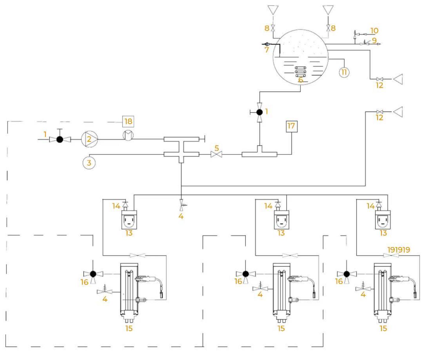
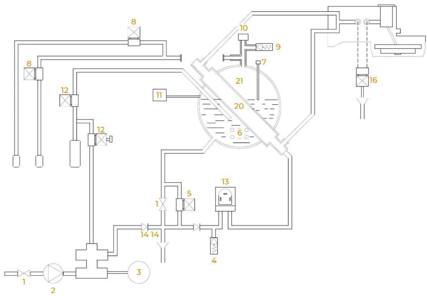
SCHEMA IDRAULICO HYDRAULIC DIAGRAM SCHÉMA HYDRAULIQUE
IT
LEGENDA SCHEMA IDRAULICO
1 Rubinetto
2 Pompa
6 Steam boiler heating element
7 Boiler level probe
8 Steam solenoid valve
9 Safety valve
10 Anti-vacuum valve
11 Digital pressostat (HP)
12 Hot water solenoid valve
13 Flow meter
14 Retain valve
15 Coffee boiler heating element
16 Delivery solenoid valve
17 Drain
18 Thermal Energy Recovery System (TERS)
19 Flow check valve
20 Heater exchange
21 Boiler
FR
LÉGENDE SCHÉMA HYDRAULIQUE
1 Robinet
2 Pompe
3 Pressostat digital (LP)
4 Vanne de décharge
11 Pressostat digital (HP)
12.1 SCHEMA IDRAULICO (NEO)
12.1 HYDRAULIC DIAGRAM (NEO)
12.1 SCHÉMA HYDRAULIQUE (NEO)
flowchart
graph TD
    A["1"] --> B["2"]
    B --> C["3"]
    C --> D["4"]
    D --> E["5"]
    E --> F["6"]
    F --> G["7"]
    G --> H["8"]
    H --> I["9"]
    I --> J["10"]
    J --> K["11"]
    K --> L["12"]
    L --> M["13"]
    M --> N["14"]
    N --> O["15"]
    O --> P["16"]
    P --> Q["17"]
    Q --> R["18"]
    R --> S["19"]
    S --> T["20"]
    T --> U["21"]
    U --> V["22"]
    V --> W["23"]
    W --> X["24"]
    X --> Y["25"]
    Y --> Z["26"]
    Z --> AA["27"]
    AA --> AB["28"]
    AB --> AC["29"]
    AC --> AD["30"]
12.2 SCHEMA IDRAULICO (DIGIT)
12.2 HYDRAULIC DIAGRAM (DIGIT)
12.2 SCHÉMA HYDRAULIQUE (DIGIT)
flowchart
graph TD
    A["1"] --> B["2"]
    B --> C["3"]
    C --> D["4"]
    D --> E["5"]
    E --> F["6"]
    F --> G["7"]
    G --> H["8"]
    H --> I["9"]
    I --> J["10"]
    J --> K["11"]
    K --> L["12"]
    L --> M["13"]
    M --> N["14"]
    N --> O["15"]
    O --> P["16"]
    P --> Q["17"]
    Q --> R["18"]
    R --> S["19"]
    S --> T["20"]
    T --> U["21"]
    U --> V["22"]
    V --> W["23"]
    W --> X["24"]
    X --> Y["25"]
    Y --> Z["26"]
    Z --> AA["27"]
    AA --> AB["28"]
    AB --> AC["29"]
    AC --> AD["30"]
13
SCHEMI CALDAIA
BOILER DIAGRAMS
SCHÉMA CHAUDIÈRE
IT
EN
FR
13.1
13.1
13.1
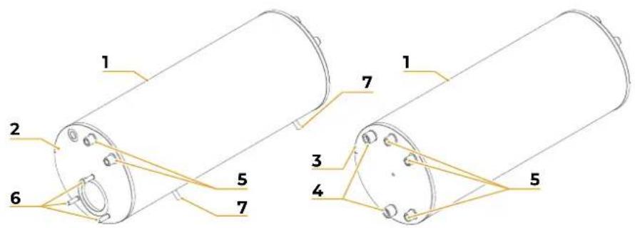
SCHEMA CALDAIA VAPORE (NEO - 2/3 GRUPPI)
STEAM BOILER DIAGRAM (NEO - 2/3 GROUPS)
SCHÉMA CHAUDIÈRE VAPEUR (NEO - 2/3 GROUPES)
DATI PROGETTO DIRETTIVA PED PROJECT DATA FOR DIRECTIVE PED DONNÉES PROJET DIRECTIVE PED
| 2014/68/CE | |
| VOLUMEVOLUMESVOLUMES | 8 l |
| TS 139°C | |
| P.V.S. 3,0 Bar | |
| PT 4,0 Bar | |
| FLUIDOFLUIDFLUIDE | H_2O |
text_image
1 2 6 5 7 3 4 5 1 7| Elemento Element Elément | Quantità Quantity Quantité | Numero Parte Part Number Numéro Partie | Descrizione Description Description | Materiale Material Matériau |
| 1 | 1 | 00051090 | Corpo caldaia Boiler body Corps chaudière | INOX AISI 316L |
| 2 | 1 | 00049622 | Flangia PR 161 PR Flange 161 Flasque PR 161 | INOX AISI 316L |
| 3 | 1 | 00049631 | Flangia PS 161 PS Flange 161 Flasque PS 161 | INOX AISI 316L |
| 4 | 2 | 00044360 | Raccordo G 3/8 M G 3/8 M fitting G 3/8 M Raccord | INOX AISI 316L |
| 5 | 5 | 00047050 | Raccordo G 1/8 M G 1/8 M fitting G 1/8 M Raccord | INOX AISI 316L |
| 6 | 3 | 00081410 | Prigioniero M6x20 M6x20 stud Boulon prisonnier M6x20 | INOX A2 |
| 7 | 2 | 00080730 | Prigioniero M6x15 M6x15 stud Boulon prisonnier M6x15 | INOX A2 |
IT
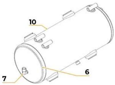
13.2
text_image
Technical diagram of a cylindrical mechanical component with numbered parts labeled 1 through 5| Elemento Element Elément | Quantità Quantity Quantité | Numero Parte Part Number Numéro Partie | Descrizione Description Description | Materiale Material Matériau |
| 1 | 1 | 00049500 | Corpo caldaia 42,5Boiler body 42,5Corps chaudière 42,5 | INOX AISI 316L |
| 2 | 1 | 00049521 | Flangia PR 42,5PR Flange 42,5Flasque PR 42,5 | INOX AISI 316L |
| 3 | 1 | 00049540 | Flangia 43,5Flange 43,5Flasque 43,5 | INOX AISI 316L |
| 4 | 4 | 00041530 | Raccordo G1/8 FC 1/8 F fittingG 1/8 F Raccord | INOX AISI 316L |
| 5 | 1 | 00080800 | Prigioniero M3x8M3x8 studBoulon prisonnier M3x8 | INOX A2 |
IT
13.3
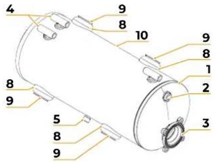
SCHEMA CALDAIA VAPORE (DIGIT - 2/3 GRUPPI)
DATI PROGETTO DIRETTIVA PED
PROJECT DATA FOR DIRECTIVE PED DONNÉES PROJET DIRECTIVE PED
| 2014/68/CE | |
| VOLUMEVOLUMESVOLUMES | 11,3 l |
| TS 130,5°C | |
| P.V.S. 1,8 Bar | |
| PT 2,7 Bar | |
| FLUIDOFLUIDFLUIDE | H_2O |
EN
13.3
STEAM BOILER DIAGRAM (DIGIT - 2/3 GROUPS)
text_image
10 7 6FR
13.3
SCHÉMA CHAUDIÈRE VAPEUR (DIGIT - 2/3 GROUPES)
text_image
4 9 8 10 9 8 1 2 8 9 5 8 9 3| Elemento Element Élement | Quantità Quantity Quantité | Numero Parte Part Number Numéro Partie | Descrizione Description Description | Materiale Material Matériau |
| 1 | 1 | 00016280 | Coppa PR ø 180PR cupø 180Coupe PR ø 180 | CU DHP 99.9 |
| 2 | 1 | 00030271 | Attacco G1/4" passante OT57G1/4" through-hole connection OT57Raccord G1/4" traversée OT57 | OT57 |
| 3 | 1 | 06200042 | Flangia 4 fori per resistenza4-hole flange for heating elementFlasque à 4 trous pour résistance | OT57 |
| 4 | 3 | 07300163 | Attacco vaporeSteam fittingRaccord de vapeur | OT58 |
| 5 | 1 | 07300071 | Attacco gasGas fittingRaccord de gaz | OttoneBrassLaiton |
| 6 | 1 | 03000070 | Fondo caldaiaBoiler bottomFond de chaudière | RameCopperCuivre |
| 7 | 1 | 07300165 | Raccordo a gomitoElbow fittingRaccordement coudé | / |
| 8 | 2 | 98030056 | Tubo scambiatoreExchanger hoseTube échangeur | RameCopperCuivre |
| 9 | 4 | 07300204 | Flangia scambiatoreExchanger flangeFlasque échangeur | OttoneBrassLaiton |
| 101/ | Corpo caldaiaBoiler bodyCorps chaudière | CU DHP 99.9 |

PARAMETRI DISPLAY DISPLAY PARAMETERS PARAMÉTRÉS ÉCRAN
IT
14.1
PARAMETRI DOSI CAFFÈ
If the set doses exceed 500ml, the letter "C" will be visible on the display, which stands for continuous dose.
By enabling pre-infusion, the machine dispenses water for a settable time (ON), stops for a settable time (OFF), and then continues dispensing coffee.
FR
14.1
PARAMÉTRÉS DOSES CAFÉ
In STD mode, the set recipe is valid for both EasyCream wands and the initial screen is the one shown in the figure.
FR
14.2
PARAMETRI DOSI LATTE
14.2.1
EASYCREAM STD
The parameters of the table refer only to the lever in the DOWN position. The lever in the UP position has only the purging function.
In DIR OR DIR (Auto) mode, it is possible to select different recipes between the two right and left levers and the initial screen is the one shown in the figure.
FR
14.2.2
EASYCREAM DIR - DIR (Auto)
The following parameters are not available for the DIGIT version:
- Set offset group 1-2-3 probe
- Set offset coffee boiler group 1-2-3 probe
FR
14.9
PARAMÉTRÉS OFFSET
The coffee boiler autofill parameter is not available for the DIGIT version.
The operating mode of the EasyCream STD / DIR wand means that:
• STD: The numbers of the active recipe are not visible on the display.
- DIR: The recipe numbers are visible on the display and it is possible to select the recipe from the initial screen.
- DIR (Auto): The recipe numbers are visible on the display and it is possible to select the recipe from the initial screen. After dispensing, the machine automatically returns to the first recipe.
FR
14.10
PARAMÉTRÉS CPU
14.Ⅱ DIAGNOSTICS CHECKS
Check the following operating phrases.
NEO / DIGIT:
• Cup warmer heating
• Hot water solenoid valve
- Pump functioning
- Steam boiler filling solenoid valve
- EasyCream 1 air valve (left-optional)
- Steam wand solenoid valve 1 (left)
- Compressor 1 (left)
- EasyCream 2 air valve (right-optional)
- Steam wand solenoid valve 2 (right)
- Compressor 2 (right)
• Safety solenoid valve
NEO:
- Group 1 coffee boiler heating
• Group 2 coffee boiler heating
• Group 3 coffee boiler heating
• 3-way solenoid valve group 1
• 3-way solenoid valve group 2
• 3-way solenoid valve group 3
• Heating group 1 - Heating group 2
- Heating group 3
FR
14.Ⅱ CONTRÔLES DIAGNOSTIC
Simonelli Group declares under its own responsibility that the espresso coffee machine identified as below complies with the directives specified below and meets the essential requirements indicated in attachment A Conformity evaluation: category 1, form A The following harmonized standards have been applied following the provisions of the directives specified below.
The technical file has been deposited at the company headquarters, at the address on the back.
The person in charge of collating and managing the technical file is Mr. Lauro Fioretti.
Model and production
See label on machine
Collections M, S, VSR editions '78 and '95 and available in the registered office
See the end of the Instruction Booklet
ATTENTION: This declaration is to be kept with the equipment at all times and must always go together with the equipment. Any use of the equipment than tor the purposes for which it was designed is prohibited. The integrity and efficiency of the equipment of the safety devices are the responsibility of the user. The declaration is null and void if the machine is modified without the express authorization of the manufacturer or if improperly installed and used in such a way that does not comply with indications in the user's manual and the instructions.
text_image
Victoria ArduinoINSPIRED BY YOUR PASSION.
Simonelli Group | Via E. Betti, 1 | 62020 Belforte del Chienti (MC) | Italy
T +39 0733 9501 | F +39 0733 950242 | info@victoriaarduino.com
www.victoriaarduino.com