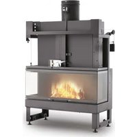
Ecomonoblocco EM16:9 3D - Frying Pan Palazzetti - Free user manual and instructions
Find the device manual for free Ecomonoblocco EM16:9 3D Palazzetti in PDF.


| Brand | Palazzetti |
| Model | Ecomonoblocco EM16:9 3D |
| Product type | Wood log insert |
| Recommended fuel | Well-dried beech/birch logs, humidity ≤25%, ideal length 35 cm |
| Ignition | Manual (ecological fire starters) or automatic via Scintilla option |
| Combustion system | Primary (adjustable) and secondary (automatic) with double combustion |
| Emission reduction | O₂Ring kit (optional) reduces harmful emissions by 80% |
| Flue gas evacuation | Connection to certified flue, minimum height 3.5-4 m, average draft 12 Pa |
| Door | Liftable and swinging, vitroceramic |
| Flue damper (VDF) | Micrometric adjustment, automatic opening when door is lifted |
| Optional ventilation | Electro-fan kit with manual/automatic control unit |
| Combustion air intake | External mandatory, insect screen, net surface area as per manual |
| Installation | Floor with adequate load capacity, self-supporting fireproof cladding, distance from combustible materials: rear 80 cm, front 170 cm |
| Routine maintenance | Cleaning the glass with ash, emptying the ash drawer, daily check |
| Periodic maintenance | Chimney sweeping at least once a year, cleaning heat exchanger and deflector |
| Safety | Do not touch hot glass, keep children away, do not use liquid fuels |
| Legal warranty | Directive EEC 1999/44/EC, subject to compliance with manual and regular maintenance |
| Spare parts | Original only, replace before complete wear |
| Delivery contents | Manual, product booklet, barcode label, hood ventilation kit, inspection hatch frame, protective glove |
Frequently Asked Questions - Ecomonoblocco EM16:9 3D Palazzetti
User questions about Ecomonoblocco EM16:9 3D Palazzetti
0 question about this device. Answer the ones you know or ask your own.
Ask a new question about this device
Download the instructions for your Frying Pan in PDF format for free! Find your manual Ecomonoblocco EM16:9 3D - Palazzetti and take your electronic device back in hand. On this page are published all the documents necessary for the use of your device. Ecomonoblocco EM16:9 3D by Palazzetti.
USER MANUAL Ecomonoblocco EM16:9 3D Palazzetti
IT
GENTILE CLIENTE,
DESIDERIAMO INNANZITUTTO RINGRAZIAR LA PER LA PREFERENZA CHE HA VOLUTO ACCORDARCI ACQUISTANDO IL NOSTRO PRODOTTO E CI CONGRATULIAMO CON LEI PER LA SCELTA.
PER CONSENTIRLE DI UTILIZZARE AL MEGLIO IL SUO ECOMONOblocco, LA INVITIAMO A SEGUIRE ATTENTAMENTE QUANTO DESCRITTO NEL PRESENTE MANUALE.
GB
DEAR CUSTOMER,
WE'D LIKE TO THANK YOU FOR HAVING PURCHASED ONE OF OUR PRODUCTS AND CONGRATULATE YOU ON YOUR CHOICE.
TO MAKE SURE YOU GET THE MOST OUT OF YOUR ECOMONOblocco, PLEASE CAREFULLY FOLLOW THE INSTRUCTIONS PROVIDED IN THIS MANUAL.
DE
7.1 KIT SCINT(SOALO PER I MODELLI
PREDISPOSTI)
7.2 RINGO
7.3 CONVOGLIATORE ARIA COMBURENTE
7.4 VENTILATORE CON CENTRALINA ESTERNA
8 MONTAGGIO REFRATTARI
9 MESSA IN SERVIZIO ED USO
9.2 PRIMA ACCENSIONE
9.3 CONTROLLO DELLA COMBUSTIONE
9.4 COME USARE LA PORTINA
9.5 VALVOLA FUMI (VDF ⑧)
-3.1-
6 INSTALLAZIONE
6.1 SCHEMA DI MONTAGGIO
←→=170cm
6.2 MESSA A TERRA
-6.5-
CONSIGLI Recommendations - Beratung:
COMIGNOLI, DISTANZE E POSIZIONAMENTO
Chimney tops, distances and positioning; Schornsteine, Abstände und Positionierung
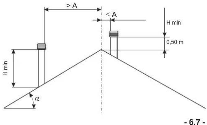
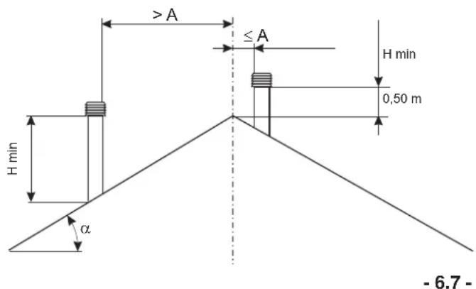
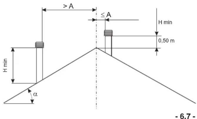
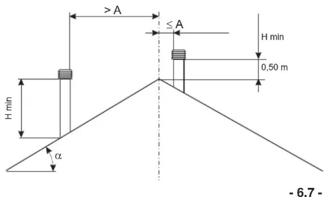
| Inclinazione del tetto Roof slant Neigung des Dachs | Distanza colmo-camino Distance ridge cap-chimney Abstand Dachfirst und Kamin | altezza min del camino (dallo sbocco) minimum chimney height Mindesthöhe des Kamins |
| α A[m] H[m] | ||
| 15° | < 1,85 | 0,5 oltre il colmo; above the ridge of the roof; über den Dachfirst |
| > 1.85 1 dal tetto; from the roof; vom Dach | ||
| 30° | < 1,5 | 0,5 oltre il colmo; above the ridge of the roof; über den Dachfirst |
| > 1,5 | 1,3 dal tetto; from the roof; vom Dach | |
| 45° | < 1,3 | 0,5 oltre il colmo; above the ridge of the roof; über den Dachfirst |
| > 1,3 | 2 dal tetto; from the roof ; vom Dach | |
| 60° | < 1,2 | 0,5 oltre il colmo; above the ridge of the roof; über den Dachfirst |
| > 1,2 | 2,6 dal tetto; from the roof; vom Dach | |
-6.10-
15x15
-6.11-
-6.12-
-6.13-
-6.14-
-6.15-
7 OPTIONAL
7.1 KIT SCINTILL®(SOLO PER I MODELLI PREDISPOSTI)

-8.1-
-8.2-

-8.3.1-
8 MONTAGGIO REFRATTARI
-8.3.2-
-8.4-
SOLO MODELLI VENTICINQUE NONI:
-8.5-
-8.6-
-8.7-
PER I MODELLI S78 3D E S66 3D:
-8.8-
-8.9-
-8.10-
PER I MODELLI S78 3D E S66 3D:
-8.11-
-8.12-
PER I MODELLI 16:9 3D:
-8.13-
-8.15--8.14-
9 MESSA IN SERVIZIO ED USO
9.2 PRIMA ACCENSIONE

9.4 COME USARE LA PORTINA
- 10.1 -
10.3 PULIZIA DEL FOCOLARE E CASSETTO CENERE
-10.2-
10.4 PULIZIA DEL CAMINO
INDEX
| 1 | GENERAL | 10 | MAINTENANCE | AND CLEANING | |
| 1.1 | SYMBOLS | 10.1 | SAFETY | PRECAUTIONS | |
| 1.2 | INTENDED | USE | 10.2 | CLEANING | THE GLASS |
| 1.3 | PURPOSE AND CONTENTS OF THE MANUAL | 10.3 | CLEANING THE FIRE BOX AND ASH BOX | ||
| 1.4 | KEEPING THE MANUAL | 10.4 | CLEANING THE FLUE PIPE | ||
| 1.5 | MANUAL | UPDATE | |||
| 1.6 | GENERAL | INFORMATION | |||
| 1.7 | MAIN ACCIDENT PREVENTION REGULATIONS TO COMPLY WITH | 11 | INFORMATION FOR DEMOLITION AND DISPOSAL | ||
| 1.8 | LEGAL | GUARANTEE | |||
| 1.9 | MANUFACTURER'S LIABILITY | ||||
| 1.10 | USER CHARACTERISTICS | ||||
| 1.11 | TECHNICAL | ASSISTANCE | |||
| 1.12 | SPARE PARTS | ||||
| 1.13 | ID PLATE | ||||
| 1.14 | DELIVERY OF THE FIREPLACE | ||||
2 SAFETY PRECUATIONS
| 2.1 | INSTRUCTIONS FOR THE INSTALLER |
| 2.2 | INSTRUCTIONS FOR THE USER |
| 2.3 | PRECAUTIONS FOR THE MAINTENANCE ENGINEER |
3 HANDLING AND TRANSPORT
4 TYPE OF FUEL
5 PREPARING THE PLACE OF INSTALLATION
| 5.1 | SAFETY | PRECAUTIONS |
| 5.2 | DRY | POSITIONING |
6 INSTALLATION
| 6.1 | ASSEMBLY | DIAGRAM | ||
| 6.2 | EARTHING | |||
| 6.3 | HEIGHT | ADJUSTMENT | ||
| 6.4 | SMOKE EXHAUST SYSTEM | |||
| 6.5 | CONNECTION TO FLUE PIPE | |||
| 6.6 | AIR INTAKE CONNECTION | |||
| 6.7 | HOT AIR DELIVERY CONNECTION | |||
| 6.8 | COUNTER-HOOD | AND | INSPECTION | PANEL |
7 OPTIONAL
| 7.1 | KIT | SCINT(DONLY FOR CERTAIN MODELS) |
| 7.2 | 2 RING | |
| 7.3 | COMBUSTION AIR INTAKE | |
| 7.4 | FAN WITH EXTERNAL CONTROL UNIT |
8 INSTALLATION OF THE REFRACTORY PARTS
9 COMMISSIONING AND USING THE ECOMONOBLOCCO
| 9.1 | DESCRIPTION OF THE PRODUCT |
| 9.2 | LIGHTING THE STOVE FOR THE FIRST TIME |
| 9.3 | CONTROLLING COMBUSTION |
| 9.4 | HOW TO USE THE DOOR |
| 9.5 | SMOKE VALVE (VDF ) |
| 9.6 | OPERATION |
1 GENERAL
Do not start using the stove until you have read and understood the contents of this manual. If you have any doubts at any time do not hesitate to call the PALAZZETTI specialized personnel who are there to help you.
Palazzetti reserves the right to modify the technical and/or functional specifications and features at any time without prior notice.
1.1 SYMBOLS
The important points in this manual are highlighted with the following symbols:

INDICATION: Indications concerning the correct use of the stove and the responsibilities of those using.

ATTENTION: A particularly important note is written here.
DANGER: Here you are warned of the possibility of bodily harm or material damages.
1.2 INTENDED USE
The PALAZZETTI Ecomonoblocco model is a fireplace suitable for burning logs of wood, used for home heating, consisting in a structure made completely of metallic material, with the firebox enclosed by ceramic glass.
The fireplace operates at its best when the firebox door is shut.
The intended use described above and configurations of the appliance described herein are the only ones allowed by the manufacturer: never use the fireplace in a way not described in the instructions provided.

The intended use described only applies to appliances that are structurally sound and installed correctly. The Palazzetti fireplace must only be installed and used inside the home.
1.3 PURPOSE AND CONTENTS OF THE MANUAL
Purpose
The purpose of the manual is to allow the user to take the necessary precautions and to have all the human and material means required for its correct, safe and lasting use.
Contents
This manual contains all the information necessary for installation, use and maintenance of the EMBL fireplace.
By complying scrupulously with the contents of this manual you will ensure a high degree of safety and productivity of the fireplace.
1.4 KEEPING THE MANUAL
keeping and consulting the manual
The manual must be kept in a safe, dry place and be available at all times for consultation by the user and by those who see to its installation and maintenance.
The instructions for use and maintenance manual is an integral part of the fireplace.
Deterioration or loss
If needed, ask Palazzetti for another copy of the manual.
Selling the fireplace
If the fireplace is sold the user must give the manual to the new owner as well.
1.5 MANUAL UPDATE
This manual reflects the state-of-the-art at the time the product was put on the market.
The products already on the market, together with their technical documentation, will not be considered by PALAZZETTI as wanting or inadequate simply because changes or adjustments have been made or new technologies have been applied to the next generation of products.
1.6 GENERAL INFORMATION
Information
If needing to provide information to the fireplace manufacturer, always refer to the product serial number marked underneath the barcode on the labels provided with this manual.
Liabilities
Upon delivery of this manual Palazzetti declines all liabilities, both civil and penal, for any accidents that may derive from the total or partial failure to comply with the specifications contained in it.

Palazzetti also declines all liabilities resulting from an improper use of the unit, incorrect use by the user or resulting from unauthorised alterations and/or repairs, or the use of spare parts that are either not genuine or not specific for this particular model.
Extraordinary maintenance
Extraordinary maintenance must be carried out by personnel qualified to work on the fireplace model to which this manual refers.
Responsibility for installation

not PALAZZETTI's responsibility to carry out the works needed to install the fireplace. Such works are entirely up to the installer who is requested to check the flue and air intake and to check if the installation solutions proposed are feasible.
All regulations required by local, national and European laws in force in the country where the appliance is installed must be observed.
Use
Use of the stove is subject to compliance with all the safety standards established by the relevant laws in force in the place of installation besides the prescriptions contained in this manual.
1.7 MAIN ACCIDENT PREVENTION REGULATIONS TO COMPLY WITH
A) Directive 2014/35 UE: "Electrical material to be used within certain voltage limits".
B) Directives 2014/30 UE: "Standardization of the legislation of member states concerning electromagnetic compatibility".
C) Directive 89/391/CEE: "Implementation of measures to promote improvement of the safety and health of workers during their working hours."
D) Directive 89/106/CEE: "Concerning the standardization of legislative, regulating and administrative guidelines of the member states on
the subject of construction products".
E) Directive 85/374/CEE: “Concerning the standardization of legislative, regulating and administrative guidelines of the state members on the subject of liability for damages due to faulty products”.
F) Directive 2014/53 UE: "Regarding radio equipment and telecommunication terminal equipment and the reciprocal recognition of their compliance".
1.8 LEGAL GUARANTEE
The user may only make use of the legal guarantee, as under the EEC directive 1999/44/CE, if he scrupulously complied with the regulations indicated in this manual, and more specifically:
• To work always within the fireplace's range of use;
- Maintenance must be constant and accurate;
- Only allow people who are capable and who have been suitably trained to use the fireplace.
Failure to comply with the regulations contained in this manual will invalidate the guarantee immediately.
1.9 MANUFACTURER'S LIABILITY
!he manufacturer declines all civil and penal liabilities, direct or indirect, due to:
- An installation that fails to comply with the laws in force in the country and with the safety rules and regulations;
- Failure to comply with the instructions given in the manual;
- An installation by unqualified and untrained personnel;
- Use that fails to conform to the safety directives;
• Alterations and repairs on the appliance not authorised by the manufacturer; - Use of spare parts that are either not genuine or specific for this particular model of fireplace
- Lack of maintenance;
• Exceptional events.
1.10 USER CHARACTERISTICS
The person who uses the fireplace must be an adult and responsible, with all the necessary technical know-how to carry out routine maintenance of the mechanical and electrical components of the fireplace.

Do not let children near the fireplace to play with it when it is working.
1.11 TECHNICAL ASSISTANCE
PALAZZETTI is able to solve any technical problem concerning the use and maintenance of the appliance's whole life cycle.
The main office will help you find the nearest authorised assistance centre.
1.12 SPARE PARTS
Use genuine spare parts only.
Do not wait until the components are worn from use before changing them.
Changing a worn component before it breaks makes it easier to prevent accidents that could otherwise lead to
serious injury to people or damage to things.
Carry out the routine maintenance checks as explained in the “MAINTENANCE AND CLEANING” chapter.
1.13 ID PLATE
The data plate under the fire floor on the right side of the fireplace includes all data on the product, including manufacturer identification, serial number and CE mark.
The serial number must always be specified for any type of request concerning the fireplace.
1.4 DELIVERY OF THE FIREPLACE
he fireplace is delivered perfectly packed in cardboard and fixed to a wooden pallet so it can be handled by forklifts and/or other means.
You will find the following items inside the fireplace:
• use, installation and maintenance manual;
- product booklet;
- bar code label
- hood ventilation kit
• inspection panel frame
- glove of protection.
2 SAFETY PRECUATIONS
2.1 INSTRUCTIONS FOR THE INSTALLER
- Make sure that the place of installation of the fireplace meets all local, national and European rules and regulations.
- Comply with the indications given in this manual.
- Check that the flue and air intake are suitable for the type of installation opted for and all local, national and European rules and regulations.
- The electrical connection must not be done using temporary or non-insulated leads.
- Check that the earthing of the electrical system is efficient.
• Always use the individual safety devices and the other protection gear as established by law.
2.2 INSTRUCTIONS FOR THE USER
- Prepare the place of installation of the fireplace in accordance with the local, national and European rules and regulations.
- Since the fireplace is an appliance that heats, its outer surfaces can get very hot.
-
For this reason we advise maximum caution when it is working, in particular:
A) Do not touch or go near the glass door as you could get burnt;
B) do not touch the smoke discharge;
C) do not empty the ashes;
D) do not do any type of cleaning;
E) make sure that children are kept away. -
Comply with the indications given in this manual.
- Comply with the instructions and warnings given on the plates on the fireplace.
- The plates are accident prevention devices and as such must be easily and perfectly legible at all times. Should they be damaged and rendered illegible it is compulsory to change them, asking the manufacturer for an original plate.
- Only use fuel that complies with the indications given in the chapter referring to fuel characteristics.
- Keep strictly to the routine and extraordinary maintenance programme to the fireplace and to the system.
- Do not use the fireplace without first having carried out the daily inspection as specified in the "Maintenance" chapter in this manual.
- Do not use the fireplace if there is a malfunction, a suspected breakage or noises.
- Do not throw water on the fireplace when it is lit or to put the fire out in the hearth.
- Do not lean against the open door during the cleaning operations.
- Do not use the fireplace as a support or anchor of any type.
- Do not clean the fireplace until the structure and ashes are completely cold.
- All work must be carried out in maximum safety and calmly.
• In the event of a chimney fire, attempt to extinguish
the fire by closing the primary air required for combustion, and then by smothering the flame. Immediately call for emergency assistance.
- The safety and filling pipes must be protected against freezing wherever this may occur.
- Do not use the fireplace as an incinerator for waste. Use only recommended fuel.
- If the stove malfunctions due to improper draught of the flue, clean it via the procedure set forth in paragraph 9.4 contacting qualified personnel.
The flue must in any case be cleaned at least once a year.
Imperfect draft of the flue may also be caused by especially severe weather conditions (typically low pressure). In this case the flue must be well heated. For this purpose, perform lighting correctly in accordance with the contents of paragraph 8.2.
2.3 PRECAUTIONS FOR THE MAINTENANCE ENGINEER
Comply with the indications given in this manual.
• Always use individual safety devices and other protection means.
- Before undertaking any maintenance, if the fireplace has been used, it must be completely cold.
Even if only one of the safety devices is not working, the fireplace is to be considered "not working".
- Disconnect from the electrical power supply before working on electrical or electronic parts or connectors.
3 HANDLING AND TRANSPORT
The fireplace is delivered with an assembled metal structure while the surround is in a separate package suitable for long-distance transport. It is advisable to wait until the fireplace arrives at the place where it will be installed before unpacking it.
The fireplace is supplied with all its parts.
Pay attention to the stove's tendency to oscillate.
Avoid sudden movements and sharp tugs when lifting the stove.
Make sure the lifting capacity of the lift truck is more than the weight of the stove. The person manoeuvring the lifting means is held completely responsible for lifting loads.

Do not let children play with the packaging materials (film, polystyrene). Suffocation hazard!
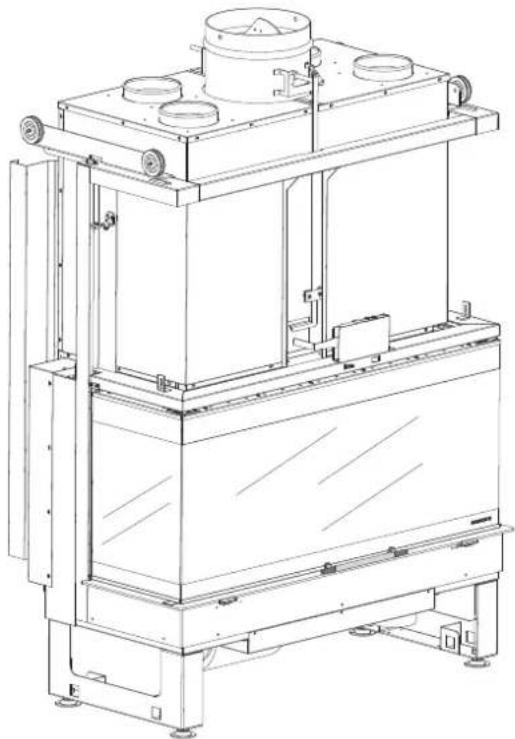
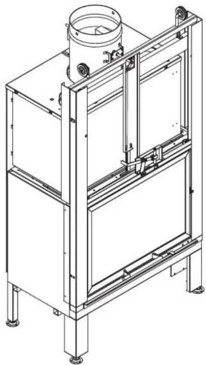
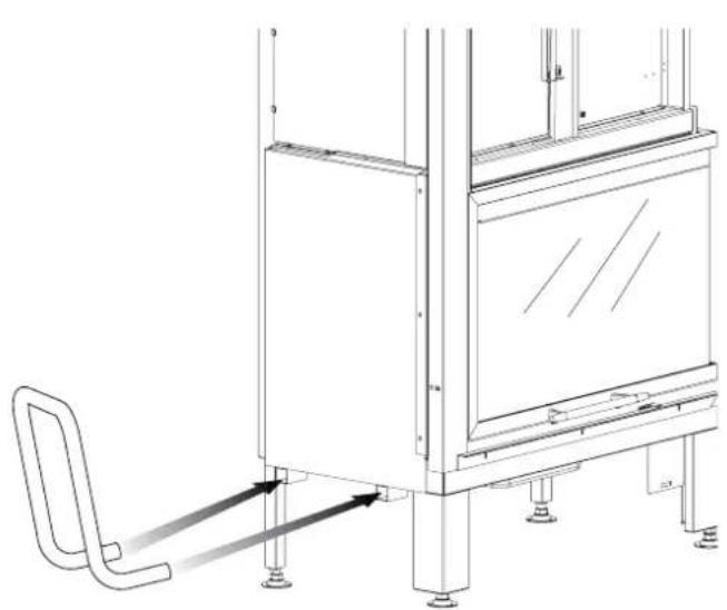
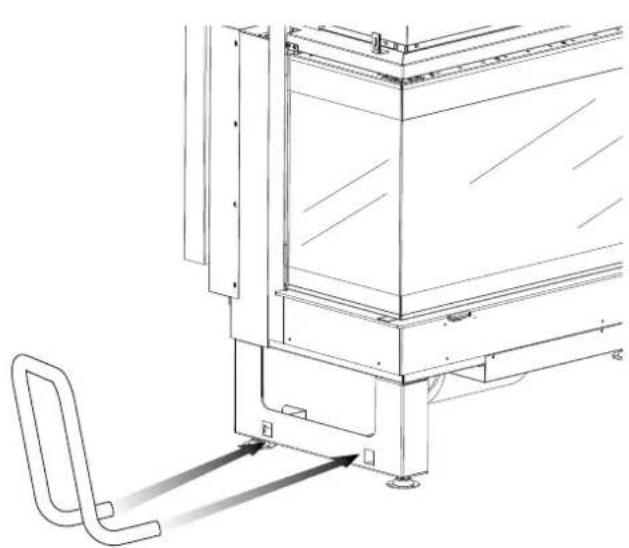
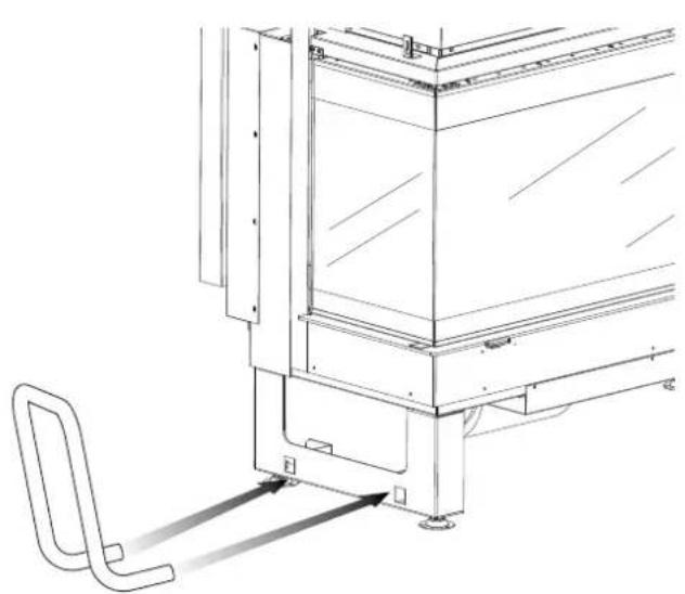
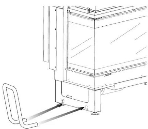
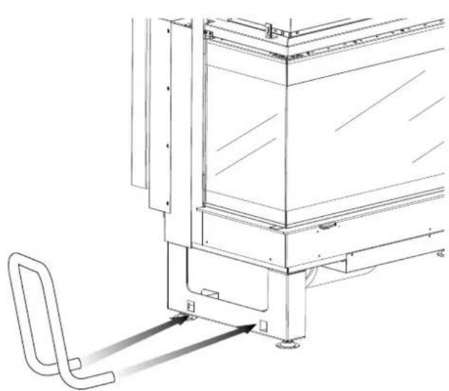
The Ecomonoblocco models are fitted with special anchor points for handling with special equipment (Fig. 3.1).
4 TYPE OF FUEL
Ecomonoblocco models are to be fed preferably with mature beech or birch wood or with wood briquettes.
Each type of wood has different characteristics that also influence combustion yield.
Use of pinewood (pine, fir) is not recommended contains high quantities of resin substances that quickly clog the flue.
It is forbidden to burn: pieces of bark, wood treated with varnish, pressed wood panels, coal, plastic materials; in this case, the guarantee on the appliance is no more valid.
IMPORTANT: the continuous and prolonged burning of wood types rich of aromatic oils (e.g. eucalyptus, myrth, etc.) will cause the rapid corrosion of the internal parts of the appliance.
The declared nominal yield of the chimney is obtained by burning the right quantity of wood, making sure not to overload the combustion chamber. The ideal length of the wood is provided by the length of the log holder.
The ideal length of the pieces of wood is of around 35 cm, which must be placed horizontally and not vertically.
Maximum allowable moisture content is 25%.
The reference standard for the fuel used is EN 14961-1 "Forest, plantation and other virgin wood".
5 PREPARING THE PLACE OF INSTALLATION
5.1 SAFETY PRECAUTIONS
The user is responsible for the work carried out in the area where the fireplace is installed; the user is likewise responsible for checking the various installation solutions proposed.

The user must comply with all the local, national and European rules and regulations.
If the floor does not have a sufficient load-bearing capacity, it is advisable to use a load-distributing plate of an appropriate size.

The appliance must be installed on a floor with an adequate carrying capacity
The stove assembly and disassembly operations must be carried out by skilled technicians only.
The qualifications and effective expertise of such skilled technicians should be verified.
Before starting the assembly or dismantling phases of the machine, the installer must comply with the safety precautions as established by law, and in particular as regards:
A) he must not work in adverse conditions;
B) he must be in perfect psychophysical condition to work and ensure that the individual and personal accident prevention devices are sound and in perfect working order;
C) he must wear accident prevention gloves;
D) he must wear safety shoes;
E) he must make sure that the area he is working in for assembling/dismantling the stove is free from obstacles.
5.2 DRY POSITIONING
- It is advisable to pre-assemble the fireplace dry so as to understand how much space the various components and air intake passageways take up.
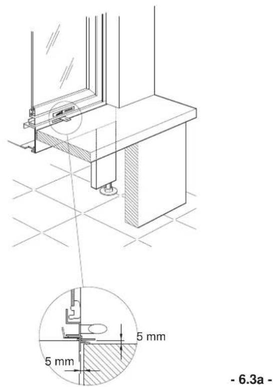
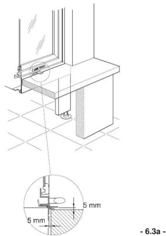
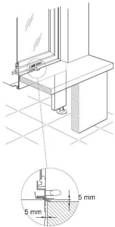
- It is necessary to match the front part of the unit with the inside edge of the marble slab, leaving a 5 mm slot so as to allow for free dilation of the Ecomonoblocco.

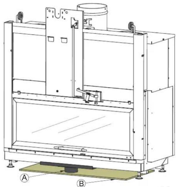
For the models with the height of the fire plan lower than 300 mm :
- remove the fresh air plenum (A)
- place the insulation plate (B) on the floor below the EMBL (Fig. 5.1)
Palazzetti claddings are realized in compliance safety and technical requirements as set forth by current standards.
5.2.1 Safety recommendations
The cladding of the fireplace, regardless of the material used, must be self-bearing with respect to the Ecomonoblocco and it must not be in contact with it.
Any wood beams, or any finishing in combustible material, must be suitably insulated (or placed outside the area of radiation of the fireplace), and must be at a distance form the Ecomonoblocco of at least 2 cm (fig. 6.1) to guarantee free air flow to avoid overheating.
Any coverings in combustible material located over the generator must be shielded by diaphragms in non-combustible insulating material.

In presence of floors made of combustible material must be placed between the fireplace and the floor a fireproof panel (already included on some models).
6 INSTALLATION
6.1 ASSEMBLY DIAGRAM
Fig. 6.1 illustrates an example assembly diagram.
- For proper installation, the smoke ducting between the fireplace and the flue must have all joints sealed using material suitable for high temperatures.
- If the fireplace is installed on a flue used previously with other fireplaces, it is necessary to clean thoroughly to avoid abnormal functioning and prevent a fire due to the combustible materials which deposit on the walls of the flue pipe.
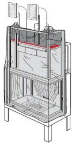
- On all Ecomonoblocco units, on the outer sides of the firebox and the hood, panels of rock wool must be installed with a thickness of 4 cm and a density of 40 kg/m 3 on an aluminium foil base, to thermally insulate the fireplace.
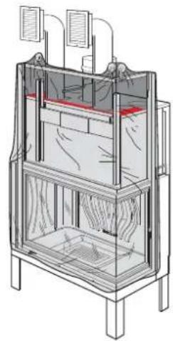
• Installation requirements include installation of a heat recovery grille as close as possible to the ceiling (around 20 cm). - Incorrect installation may compromise safety of the unit.
• The cladding must be made of fireproof material. - If there are flammable structures or materials on the back of the firebox, the distance from the combustible materials must be 80 cm.
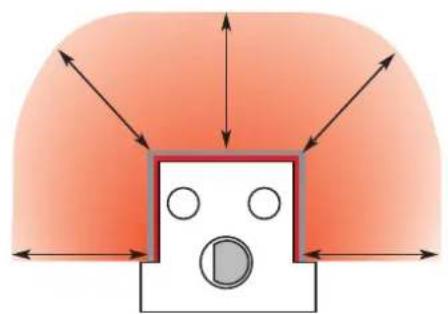
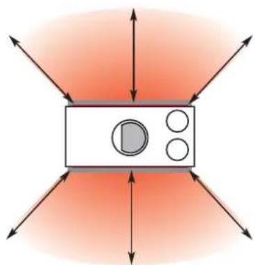
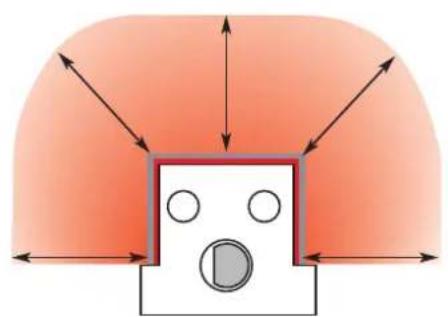
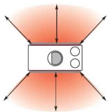
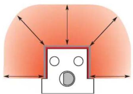
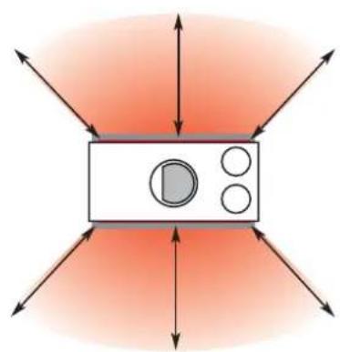
- All combustible materials must be placed at least 170 cm away from the area where heat radiates from the glass door. (Fig. 6.2).
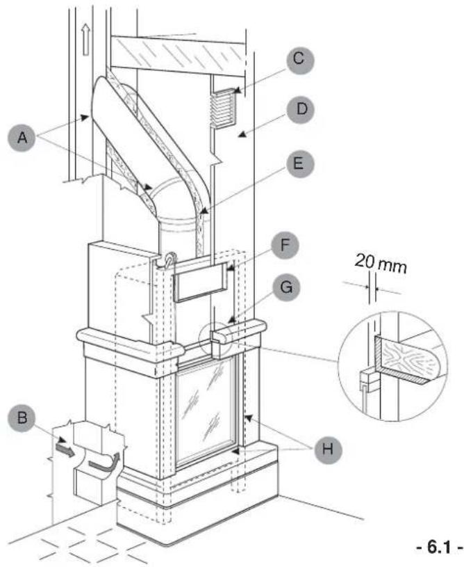
A) SEAL
B) EXTERNAL AIR INTAKE (UNDER FIRE BED)
C) HEAT RECOVERY GRILLE
D) COUNTER-HOOD AND FIREPROOF LOAD BEARING STRUCTURE
E) CLADDING IN CERAMIC FIBRE OR ROCK WOOL WITH EXTERNAL ALUMINIUM FOIL
F) INSPECTION PANEL
G) SHIELD THE WOOD PARTS WITH FIREPROOF MATERIAL
H) MINIMUM DISTANCE 5 mm BETWEEN CLADDING AND FIREPLACE STOVE
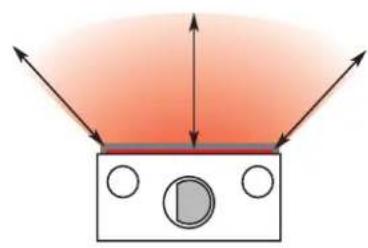

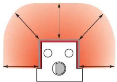
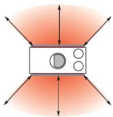
-6.2-

-6.3a-
A
-6.3b-
-6.4-
6.2 EARTHING
The Ecomonoblocco is equipped with a screw for the equipotential connection which can hold a cable with a section from 2.5 mm 2 to 6 mm 2 , to be used to obtain equipotentiality of the earth in compliance with current standards. This fixture is located on the lower part of the Ecomonoblocco and is indicated by the symbol ⏻.
Also the flue must be fitted with a own earth in compliance to the standards in force.
6.3 HEIGHT ADJUSTMENT
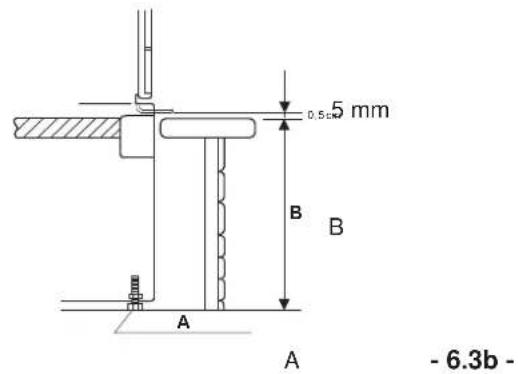
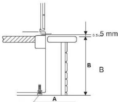
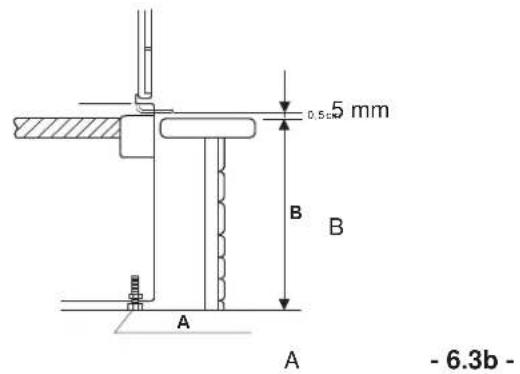
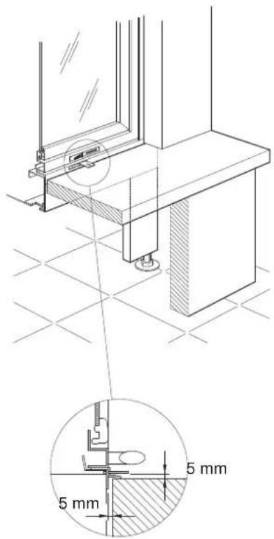
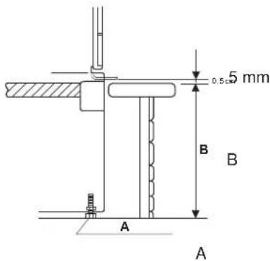
To adjust the final height of the Ecomonoblocco (cladding fire bed height), just turn the adjustment screws locted on the base. Adjsut the screws (Fig. 6.3a: A-adjustment screw, B-fire bed height), until the marble cover profile on the Ecomonoblocco is at the proper height compared to the cladding, making sure that the bottom of the fireplace is level. For cladding with fire bed H 30 cm, remove the adjustment screws. Where featured, the lever for the adjustment of combustion air must be about 0.5 cm over the cladding surface, so that it is easily usable. (Fig. 6.3b).
6.4 SMOKE EXHAUST SYSTEM
The Ecomonoblocco must be connected to a smoke exhaust system so as to ensure combustion products are suitably discharged into the atmosphere, in accordance with standards EN 1856-1-2 EN 1857, EN 1443 EN 13384-1-3, EN 12391-1 and UNI 10683, both as regards sizing and the construction materials used.
• The CHIMNEY must be sized as described on the datasheet (average draught 12 Pa with door closed).
- The components making up the combustion product exhaust system must be declared as being suitable for the specific operating conditions CE marked (declaration of conformity or European technical approval for the product).
- The flue must have a constant cross-section along its entire height.
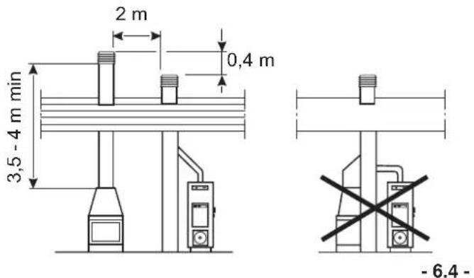
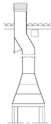
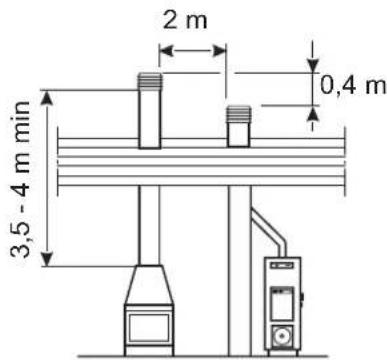
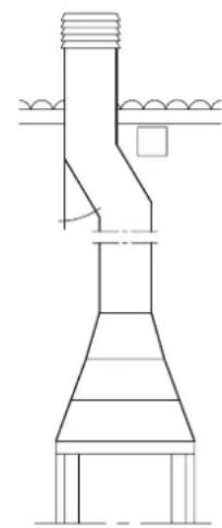
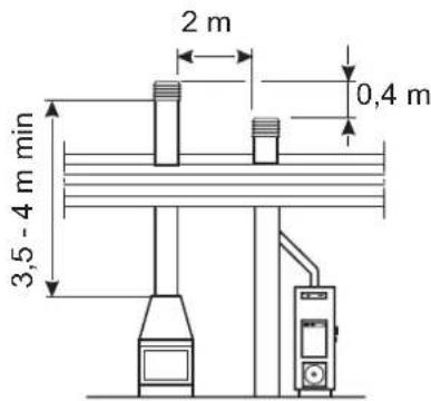
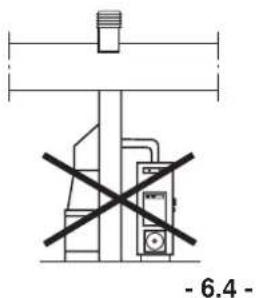
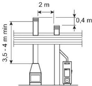
• The minimum recommended height is 3.5 to 4 m (Fig. 6.4).
- A collection chamber should be featured at the bottom of the flue to collect any solid residues and condensate. IMPROVISED flues made using unsuitable materials are illegal and affect correct operation of the Ecomonoblocco.
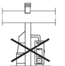
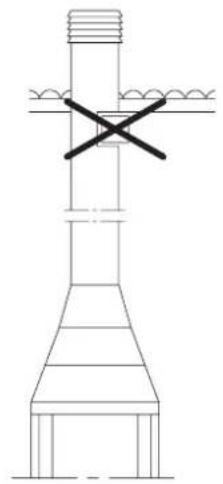
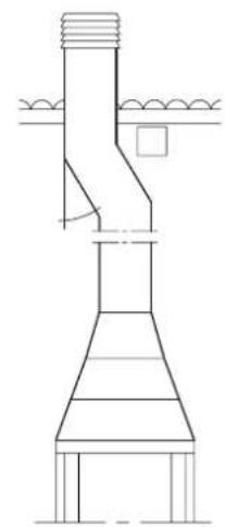
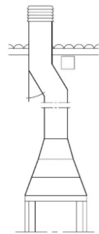
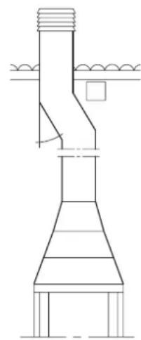
- A PERFECT DRAUGHT is above all the result of a flue that is clear of obstructions such as chokes, horizontal sections or corners; any axial displacements should be at a maximum angle of 45° compared to the vertical axis, (better still if it is only 30° ). These displacements should preferably be effected near the chimney top (Fig. 6.5).
- The SMOKE connection between the fireplace and flue should have the same cross section as the stove's smoke outlet. The smoke fitting must be sealed and the use of flexible metallic pipes is prohibited. Changes in direction in respect to the smoke outlet of the appliance must be executed using elbows not exceeding 45° in respect to vertical.
• The CHIMNEY TOP shall be the WINDPROOF type with an inside cross section equivalent to that of the flue and with a smoke outlet passage section at least
DOUBLE the internal one of the flue.
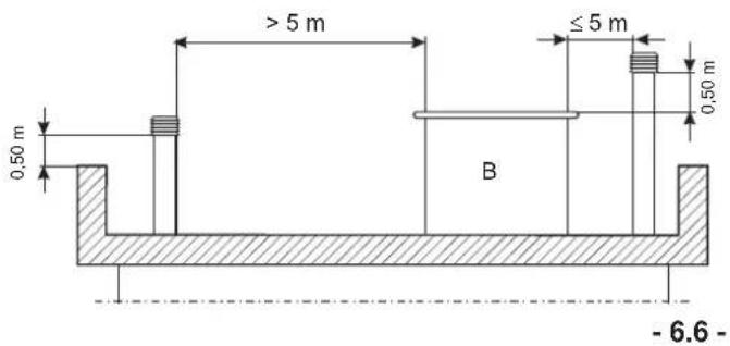
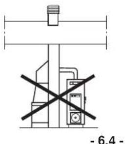
- To avoid draught problems, each stove should have its own flue. If there is more than one flue on the roof the others should be situated at a distance of at least 2 metres and the stove's chimney top should be at least 40 cm ABOVE the others (Fig. 6.4). If the chimney tops are near each other install some dividing panels.
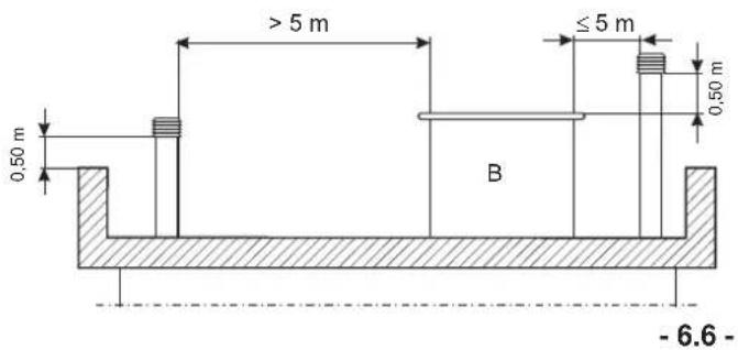
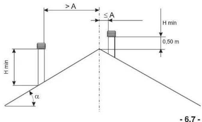
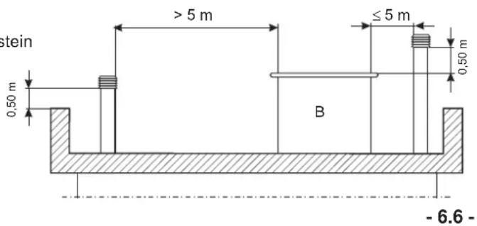
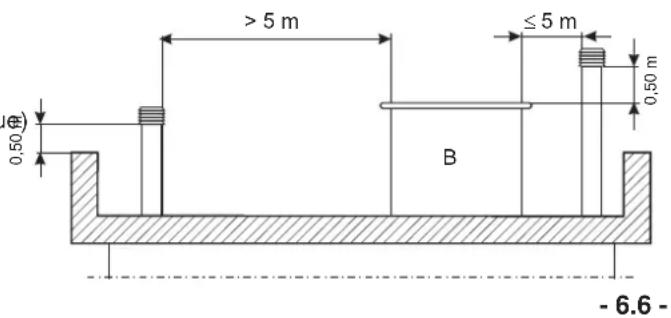
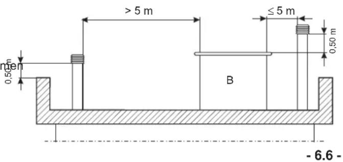
- Fig. 6.6 (FLAT ROOF; B service compartment) and Fig. 6.7 (SLOPING ROOF; B above the ridge) show suggestions on the minimum distances and chimney top positions.
- If the stove is installed with a flue that has already been used it should be cleaned thoroughly to avoid malfunctions and the danger of unburned parts deposited on the inside from catching fire.
• Under normal conditions of use of the stove the flue should be cleaned at least once a year except for different regulations.
-6.5-
CONSIGLI Recommendations - Beratung:
6.5 CONNECTION TO FLUE PIPE
Dimensioning the flue must be executed in accordance with EN 13384-1.
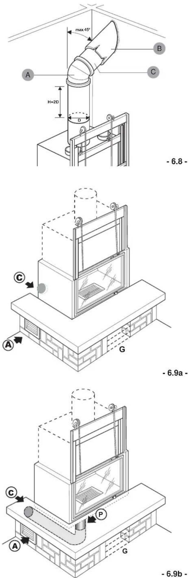
It is advisable to make the connection for smoke outlet between the fireplace and the flue pipe with curves and metallic pipes of a suitable thickness, taking care not to exceed and inclination of 45° (see Fig. 6.8:- A - curve, B - ceramic fibber rock wool insulation, C - short section) if the flue pipe is not perpendicular to the flue pipe.
When the connection has been made, it is advisable to insulate the metallic pipes of the smoke outlet with rock wool which may be externally covered with aluminium foil.
- Do not use fibre glass wool or insulation with a paper base: they may catch fire.
- All components making up the chimney system must be declared as being suitable for the specific operating conditions and CE marked.
6.6 AIR INTAKE CONNECTION
It is necessary to provide an external air intake to ensure the flow of combustion air to the fireplace (C).
The dimensions of the hole must comply with the values set forth in the table of technical data shown in the "Product booklet".
According to local standards in force, air intake could be taken directly from the room or connected to the fireplace.
- Is forbidden the intake of air for combustion from garages, rooms where flammable materials are stored or where there is danger of fire.
- The combustion air intake should be protected by an anti-insect grille and placed where it can not be accidentally obstructed, and made in such a way that the useful cross-section allows the right amount of oxygen to reach the fireplace.
In the room where the fireplace is located, if there are one or more extraction fans (exhaust hoods and the like), there may be problems with combustion due to lack of combustion air.
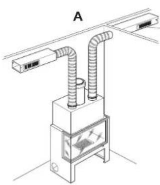
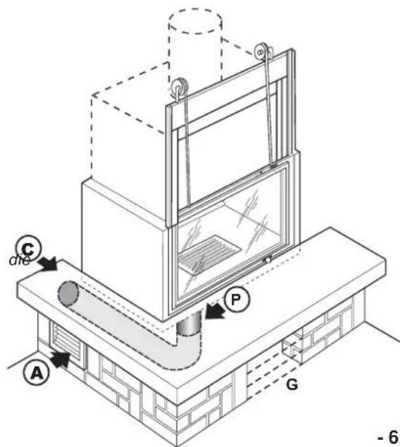
For rooms greater than 25 m 2 it is advisable to provide a room air recirculation grille (A) alongside the cladding or use the wood compartment if there is one (G) (Fig. 6.9a).
6.6.1 Combustion air intake
Some models of Ecomonoblocco may be fitted (as standard or as an option) with a special flange, located in the bottom compartment (P, Fig. 6.9b), for combustion air connection to the outside air intake (C) via suitable ductwork. For connections exceeding 1 m in length, the diameter of the combustion air intake duct must be increased.

On Ecomonoblocco models with smaller support feet, this solution is only available when applying the extension leg kit.
6.7 HOT AIR DELIVERY CONNECTION
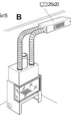
6.7.1 Connection in counter-hood for single-room heating
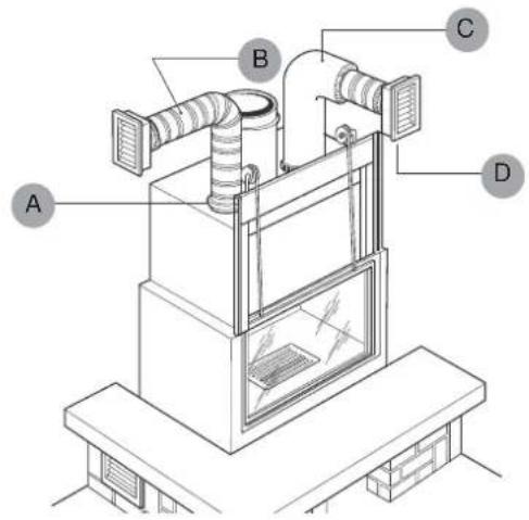
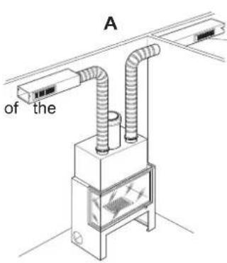
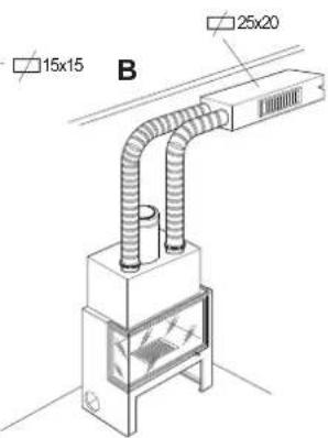
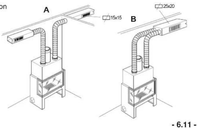
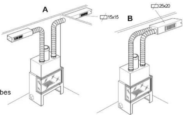
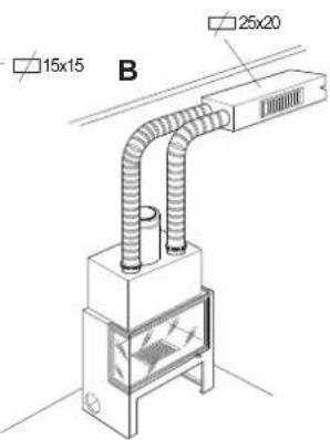
Install the flexible pipes (diameter 140 mm) for hot air distribution to the outlet nozzles, above the hood, securing them with the special clamps. Soundproof the pipes by cladding them with the insulating material (rock wool mat) (Fig. 6.10: A-clamps, B- distribution pipe, C-insulation, D-outlets).
6.7.2 Connection to ducting for multi-room heating
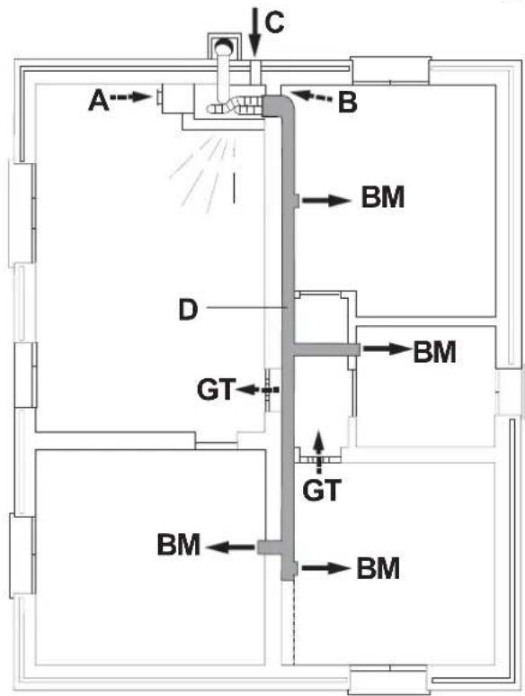
To heat more than one room it is possible to realize metallic conduits for air distribution in accordance with the following scheme:
- flexible aluminium pipe - maximum length 3-4 m per conduit
- smooth metallic pipe or ducting - length up to 12 m on a single conduit; 6+6 m on a dual conduit.
Install an outlet in the same room as the fireplace. The second conduit can be used to carry hot air to the other rooms of the home. As an alternative, connect the hot air delivery to a flexible pipe until the inlet distribution ducts. The conduits for air distribution must have an internal cross-section of 25x20 cm, made of smooth galvanized sheet metal and insulated with 30 mm of fiberglass wool to prevent heat dispersion and noise.
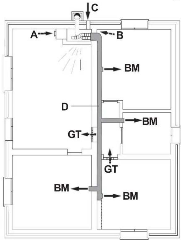
When the fireplace is used is used to heat 2 or more adjacent rooms, it is indispensable to allow for air circulation so as to have the same temperature in the various rooms. Therefore, place ventilation grilles on the doors or leave the doors ajar.
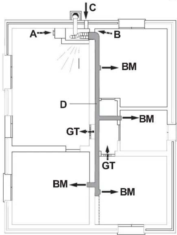
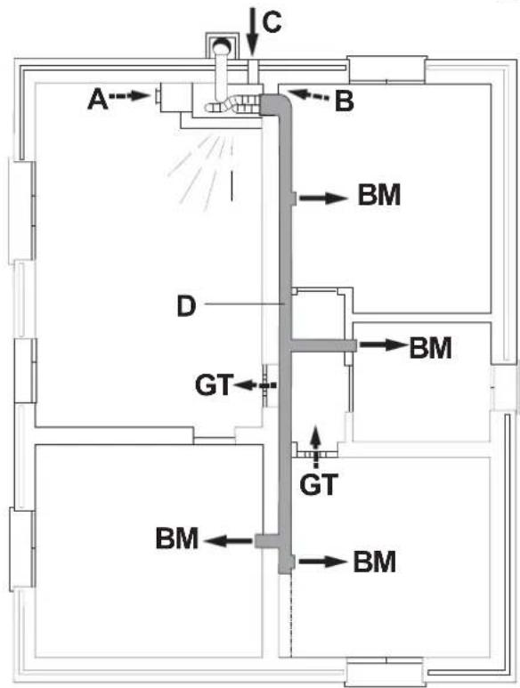
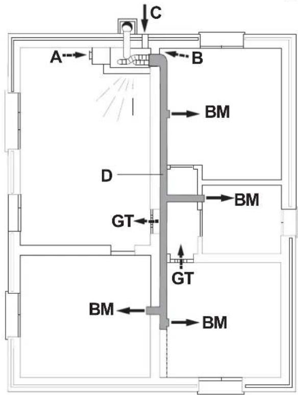
AIR DUCTING DIAGRAM (Fig. 6.12)
BM = Ceiling delivery outlet complete with calibration shuttle
GT= Ventilation grille in lower part of door
A+B = Room air intake grilles with 14 cm holes, connected with an aluminium flexible pipe to the fan container box, with or without fixed grille, without shutter
C = External air intake opening located under the grate for combustion, with fixed-slot grill, anti-insect mesh, air calibration shutter, 15-20 cm diameter hole, depending on fireplace model.
D = Hot air distribution with galvanized steel ducting located in the ceiling, net internal cross-section 25x20 cm, for a length of about 12 m, cladding with external insulation in fiberglass wool with a thickness of 3 cm, possible coveringin plasterboard.
-6.10-
-6.11-
-6.12-
6.8 COUNTER-HOOD AND INSPECTION PANEL
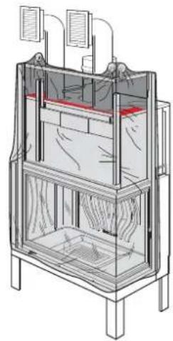
For the realization of the counter-hood, we recommend the use of plasterboard fireproof, because it is easy to work with and because it will keep from overloading with boards and beams the structure of the monobloc, the marble architrave and the wood beam which must NOT act as load-bearing structures
Before constructing the counter-hood, the control unit for the fan must be installed if it is included.
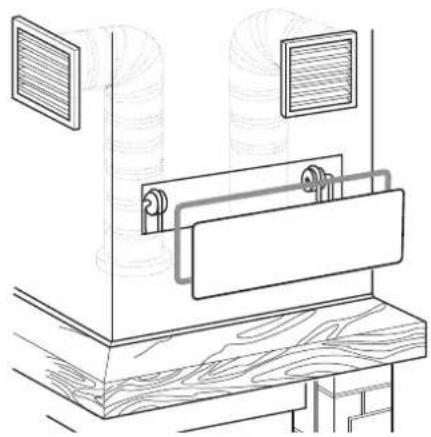
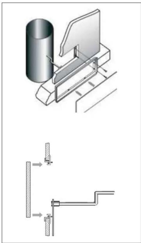
The inspection panel is to be attached to the external side of the counter-hood (see point 6.13).
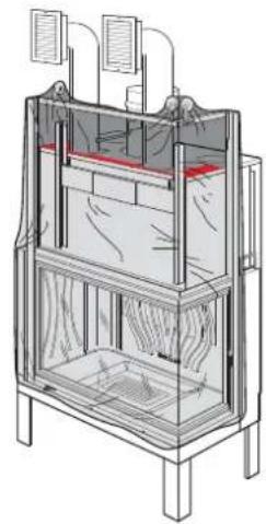
- During realization of the hood it is indispensable to protect the door sliding frame with nylon covering secured with adhesive tape (Fig. 6.14). This will keep dust, mortar or foreign objects from getting stuck between the outlets and the runners, thus keeping the door itself from sliding. Remove the protection when work is complete through the inspection grille.
- Before carrying out final assembly, it would be a good idea to make a smoke test, which means operating the fireplace both with the door open and with the door closed.
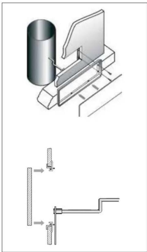
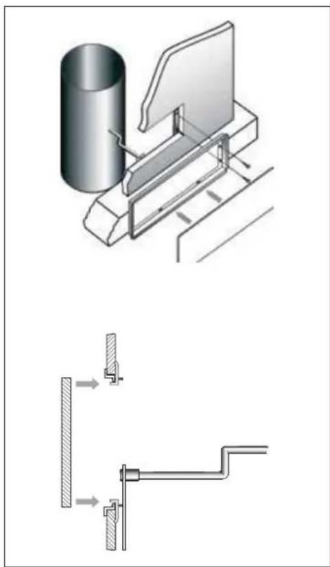
6.8.1 Inspection panel installation and VDF adjustment
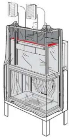
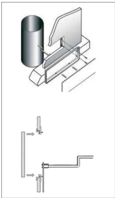
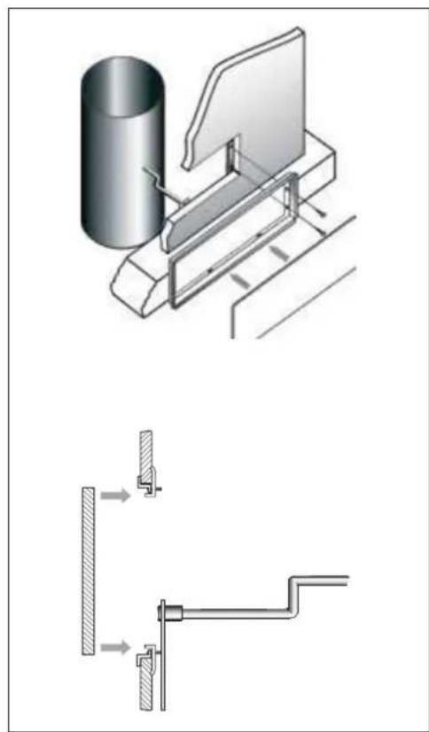
The panel must be installed on the counter-hood using the counter-frame provided. The panel is required for any inspections which may be necessary inside the counter-hood.
For installation follow these instructions:
A) On the plasterboard counter-hood, make a hole of about 37 x 13.8 cm centred on the axes of the smoke valve pin. Then insert the conter-frame and secure it with the two brackets (vertically or horizontally) by tightening the Philips-head screws as shown in figure 5.15. For masonry counter-hoods, cement the fixed counter-frame, respecting the centring of the VDF valve pin.
B) Place the panel so that it adheres to the counter-frame, then press until it is completely inserted on the counter-frame.
C) Also place the heat recovery grille, dimensions 31x8 (provided) in the upper part of the counter-hood (Fig 6.15).
-6.13-
-6.14-
-6.15-
7 OPTIONAL
7.1 KIT SCINTILL®(ONLY FOR CERTAIN MODELS)
Scintilla ® is a device that allows automatic ignition of the fireplaces in the Ecomonoblocco series. Ignition may take place by means of a switch which may or may not be timer-controlled, or by GSM with an optional actuator.
7.2 RONG ®
O2 Ring is the revolutionary system for reducing harmful emissions produced by combustion gases.
Installing the O2 Ring kit before the chimney connection reduces harmful emissions by up to 80%.
7.3 COMBUSTION AIR INTAKE
This component, installed underneath the Ecomonoblocco, is used to carry combustion air from the outside through suitable ductwork, directly into the fireplace. This avoids taking in cold outside air into the room.
7.4 FAN WITH EXTERNAL CONTROL UNIT
The kit is composed of the control unit, and electric fan and a minimum temperature thermostat or probe. The control unit is used to switch the fan on and off, manually or automatically, as well as to control motor speed manually, automatically or proportionally.
In Ecomonoblocco versions with low fire bed kit, the fan kit also includes the extension feet for installation of the fan.
In 16:9 3D model, before mounting the fan kit make sure to turn up the supporting feet of the stove at least 5 cm from the minimum size.
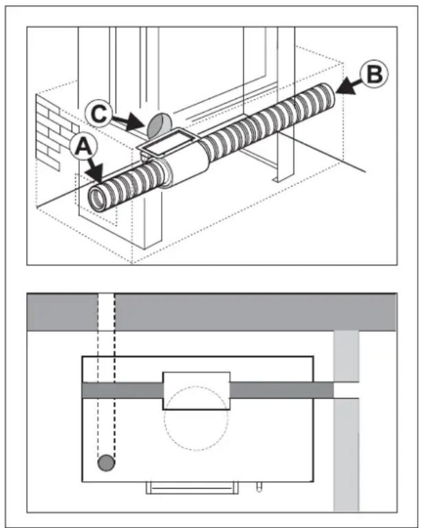
7.4.1 ELECTRIC FAN CONNECTION (OPTIONAL)
In addition to the combustion air intake → it is also necessary to provide air intakes for the fan.
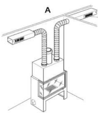
A→Room air intake to heating circuit fan, located laterally to the cladding (diameter 14 cm) with grille measuring □15x25.
B→Ambient air intake connected to an adjacent room (except kitchen, bathroom, sleeping room), dimensions ∅14cm □ 15x25) (fig. 7.1).
Connect the air convection fan (V) to the inlet pipes below the firebox.
On Ecomonoblocco models with smaller feet, this solution is only possible by installing the extension leg kit.
Is forbidden to avoid leaving the fan disconnected from the aspiration pipes under the fire draw in smoke from the fire box and heating circuit.
For further details, see the instructions included in the fan kit.
If installation is performed as shown in Figure 5.8b, make sure there is a distance of at least 50 cm between the combustion air intake and the fan intake.
-8.1-
-8.2-
-8.3.1-
8 INSTALLATION OF THE REFRACTORY PARTS
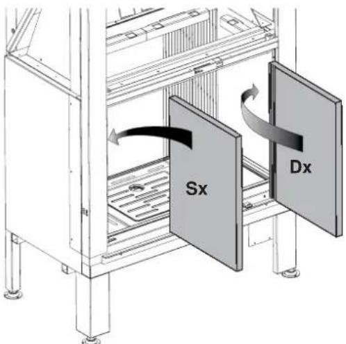
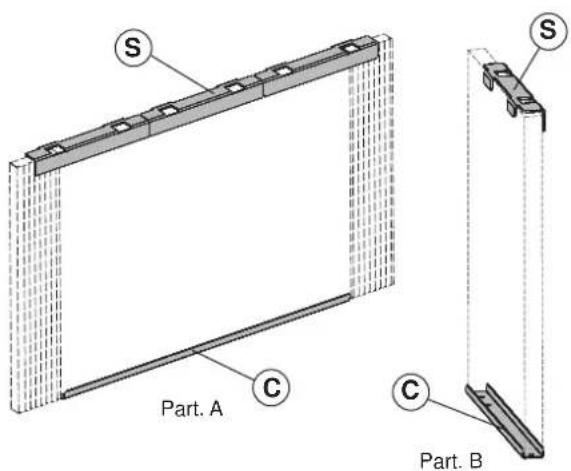
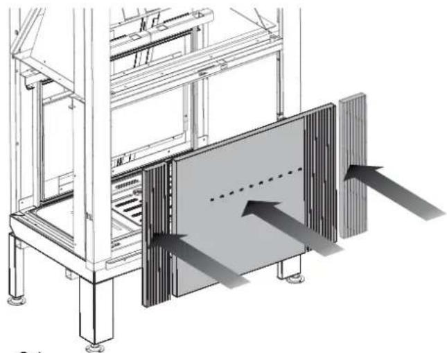
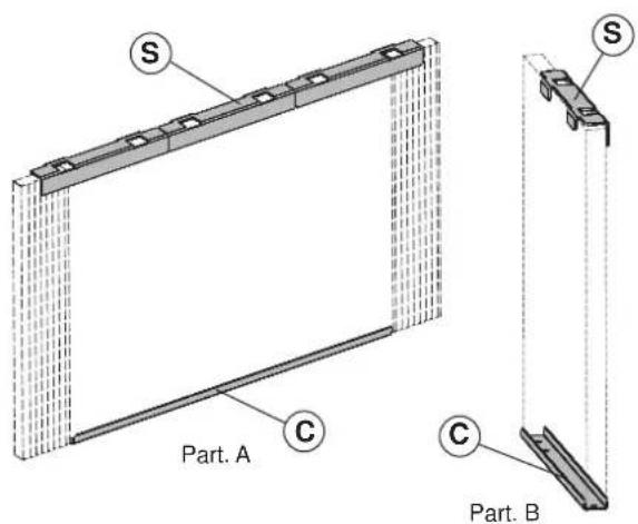
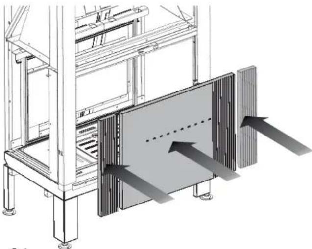
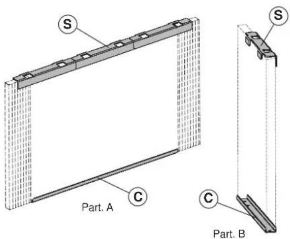
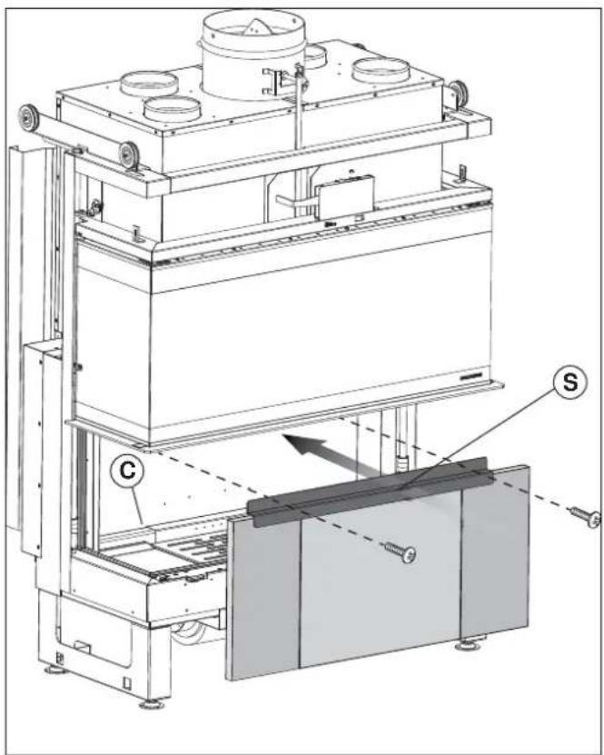
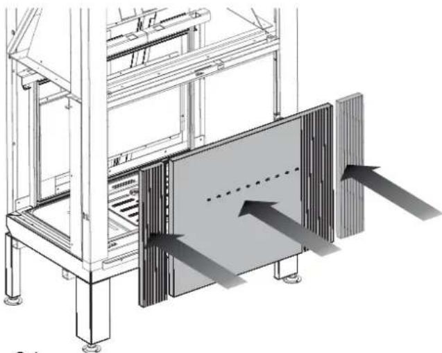
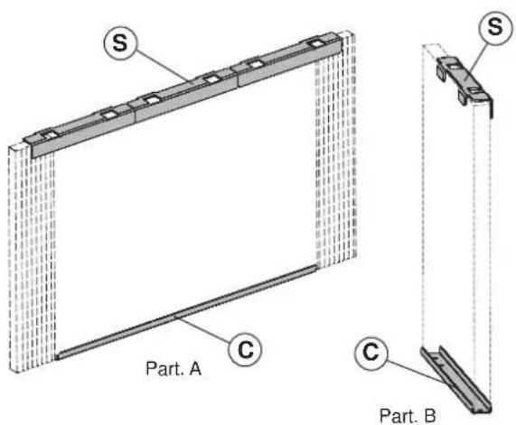
- Insert into the ECOMONOBLOCCO the refractory plates with the post-combustion holes and their respective extensions (according to the model) (Fig. 8.1), by placing them into their proper spaces (C, Fig. 8.3.1 Part. A), let them lean on the back side of the firebox and fix them through the upper bracket (S, Fig. 8.3.1 Part. A);
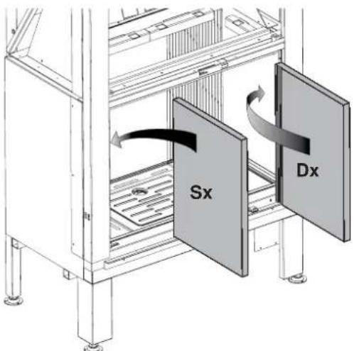
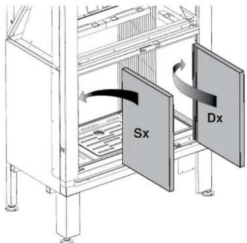
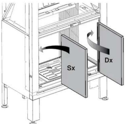
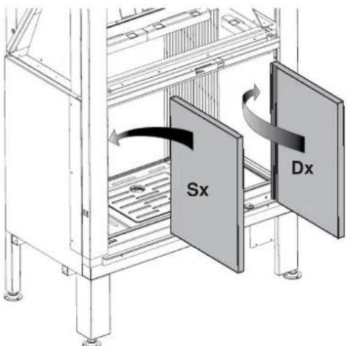
- Insert into the ECOMONOBLOCCO the right and left sides (according to the model) (Fig. 8.2) by placing them into their proper spaces (C, Fig. 8.3.1 Part. B), let them lean on the corresponding side of the firebox and fix them through the upper bracket (S, Fig. 8.3.1 Part. B).
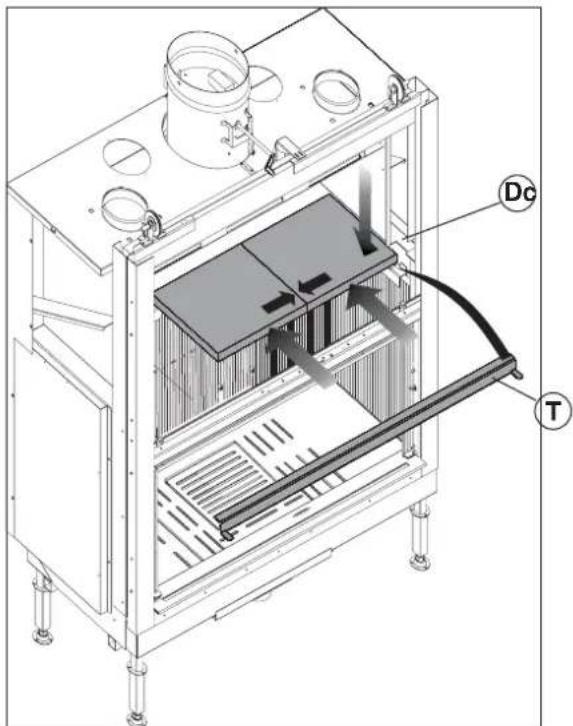
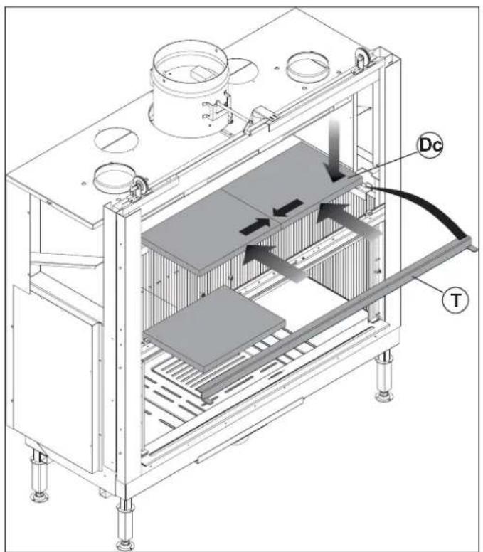
- Insert the central deflectors support (T) and place it towards the front part of the ECOMONOBLOCCO, place the central deflectors (Dc) by letting them lean on the back and lateral refractory plates, and insert the support in the proper holes. Joint the deflectors together in order to create an unique element, leaving the same space on both left and right ends (Fig. 8.3.2).
-8.3.2-
-8.4-
Models Venticinque Noni only :
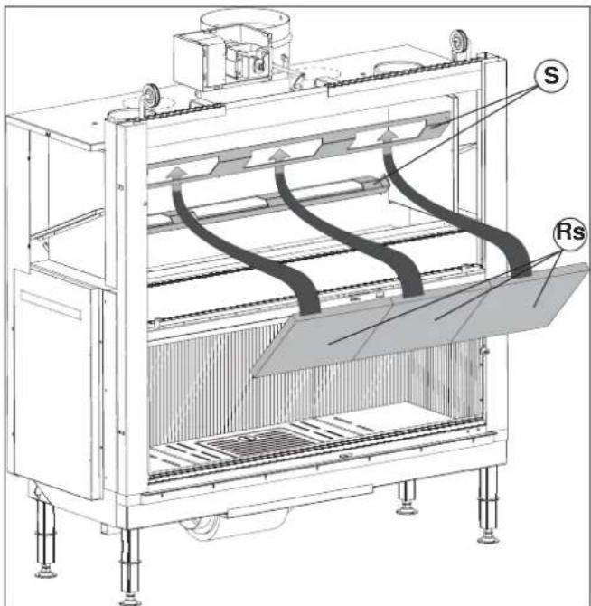
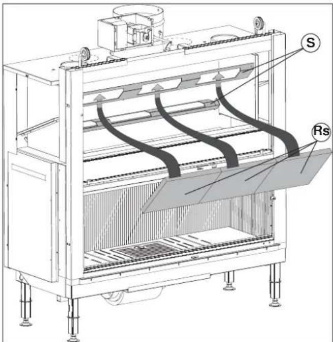
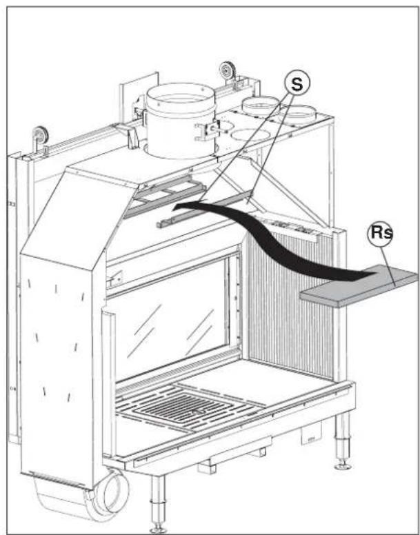
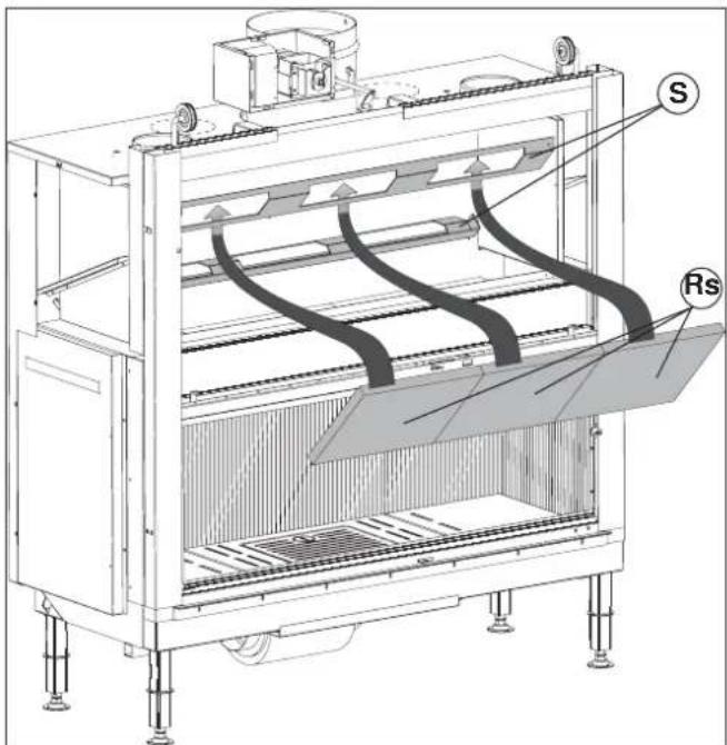
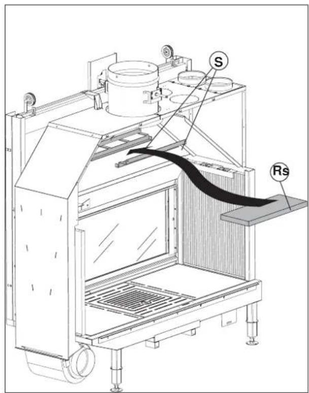
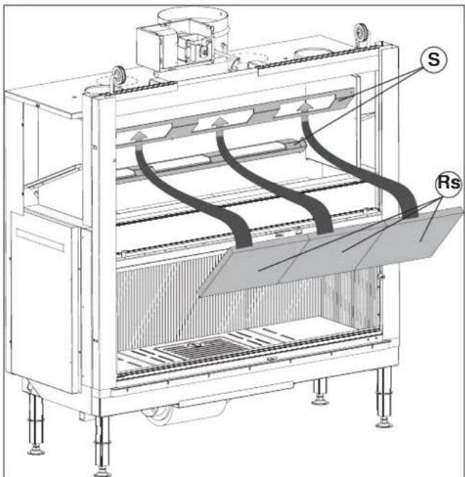
insert the upper refractory plates (Rs) (28,5x33 cm) in their corresponding location (S, Fig. 8.4);
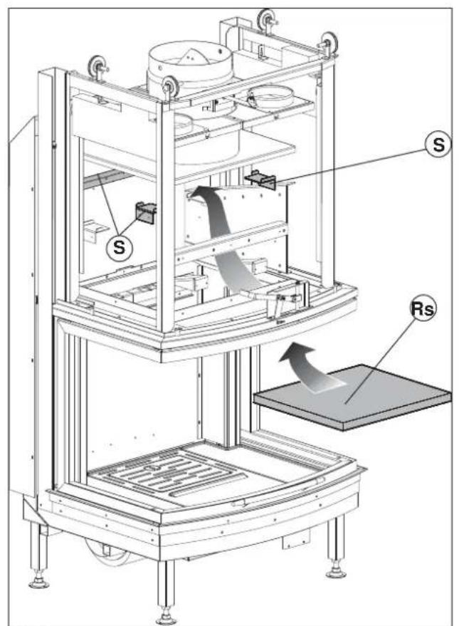
Mod. Venticinque Noni: insert the central deflectors support (T) and place it towards the front part of the ECOMONOBLOCCO, place the central deflectors (Dc) (28,5x 38 cm) by letting them lean on the back and lateral refractory plates, and insert the support in the proper holes. Joint the deflectors together in order to create an unique element, leaving the same space on both left and right ends (Fig. 8.5).
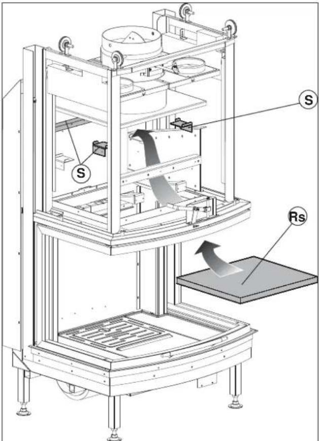
fig. 8.6: superior refractory installation - model Venticinque Noni double front.
-8.5-
-8.6-
-8.7-
For the 3D versions S78 and S66 :
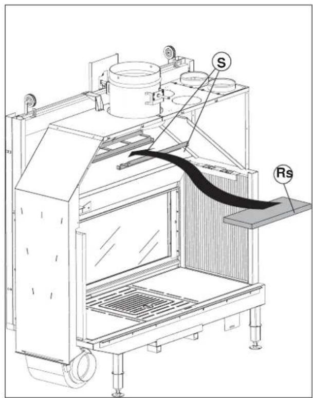
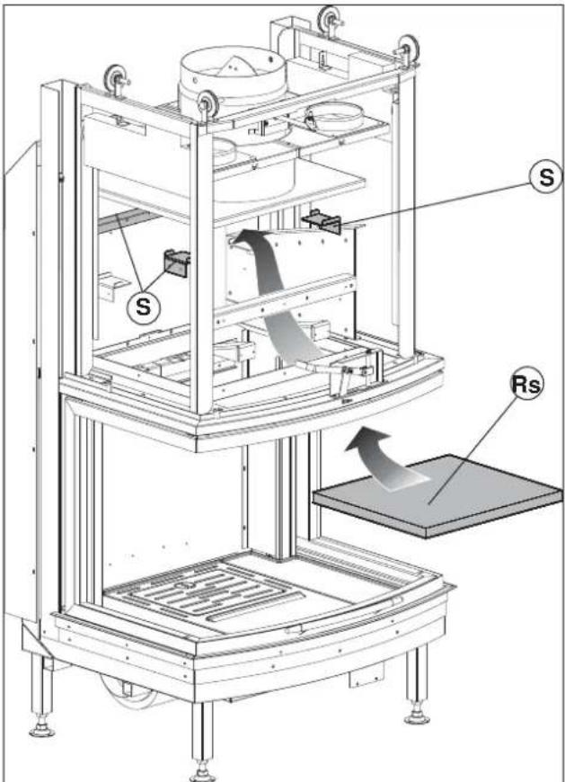
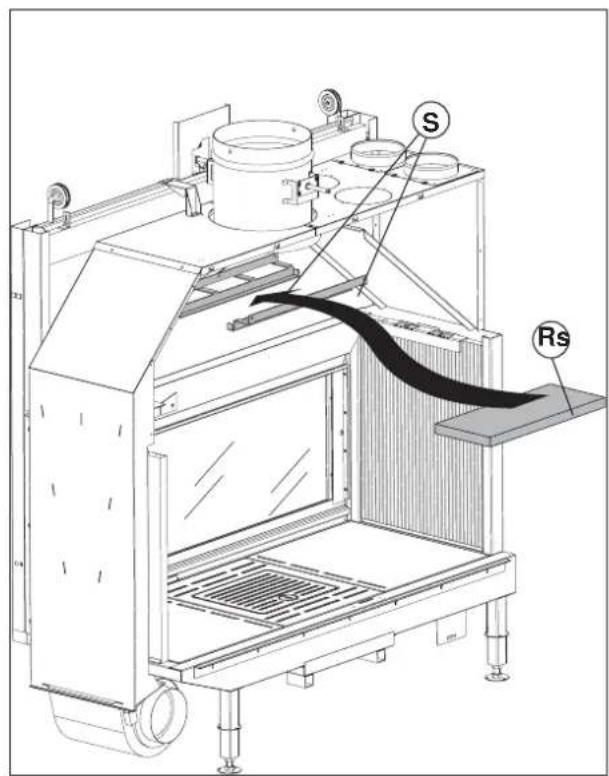
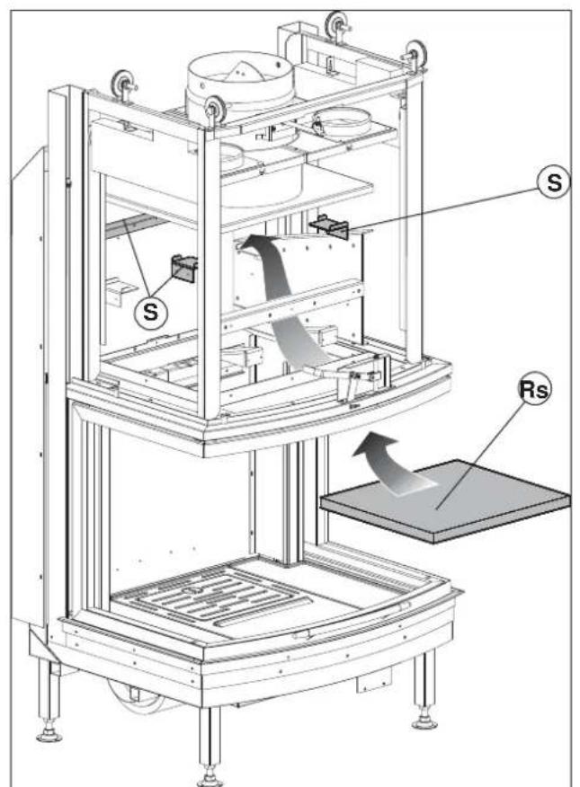
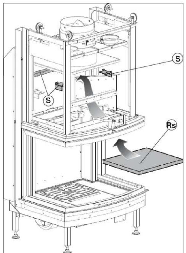
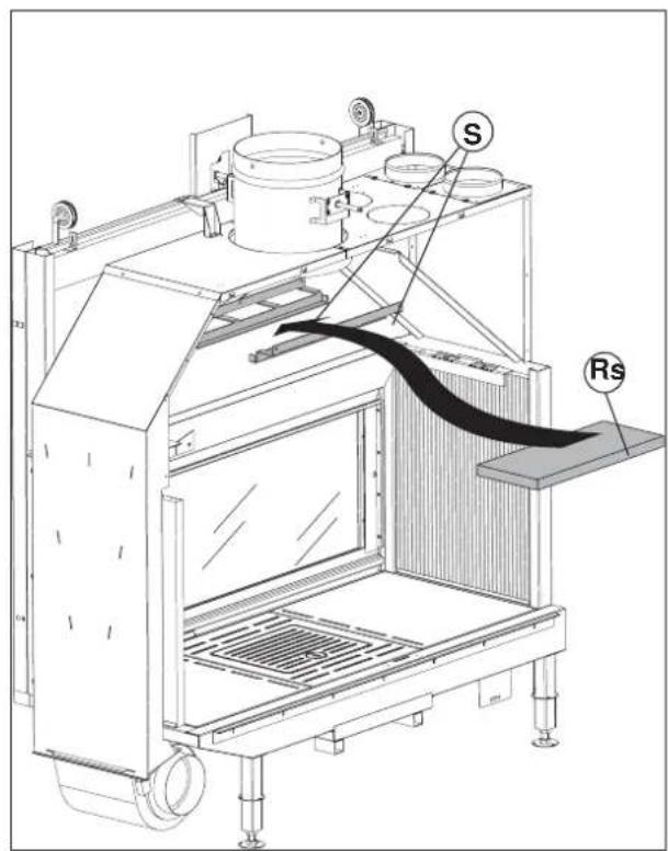
- insert the upper refractory diaphragm (Rs) by passing it through the hood, and then lodging it in the appropriate housings (S), Fig. 8.7;
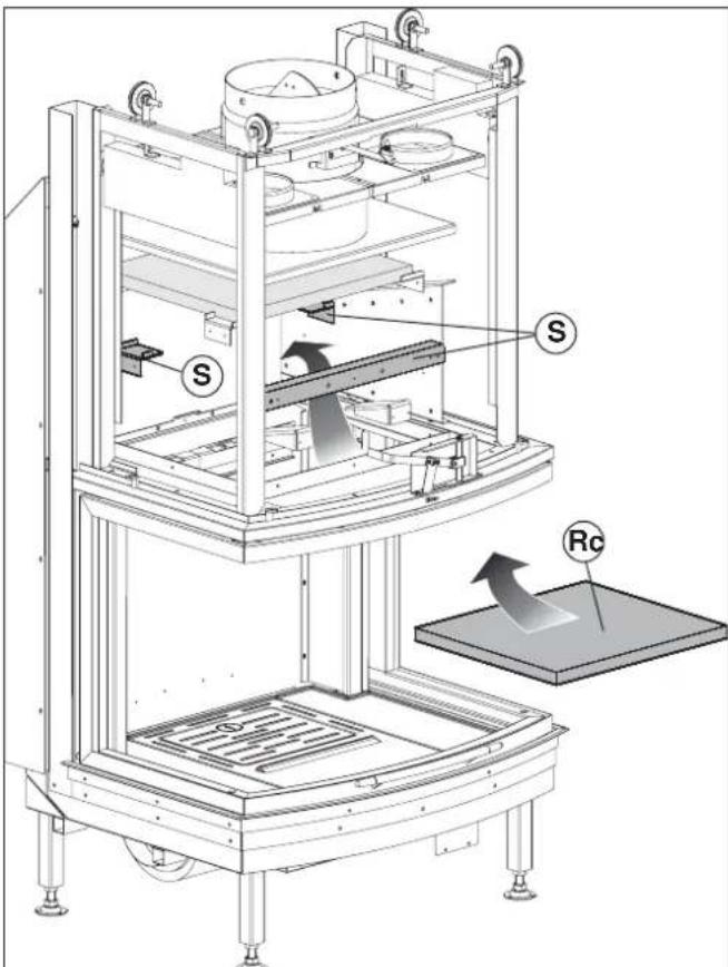
- insert the central refractory diaphragm (Rc) by passing it through the hood, and then lodging it in the appropriate housings (S), Fig. 8.8;
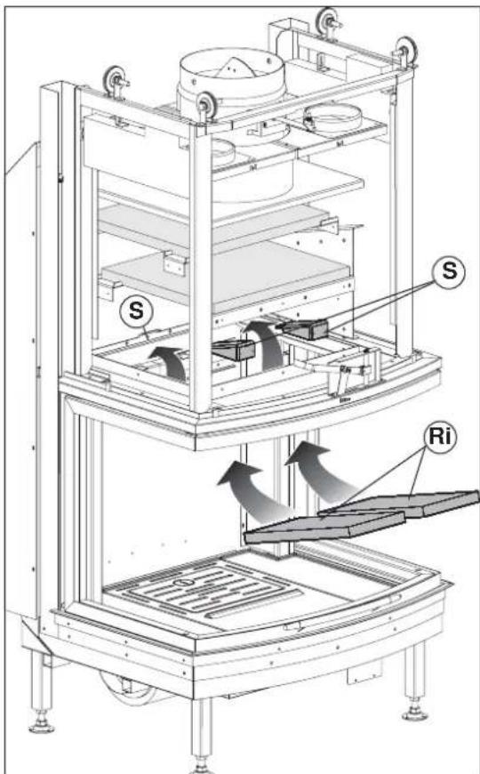
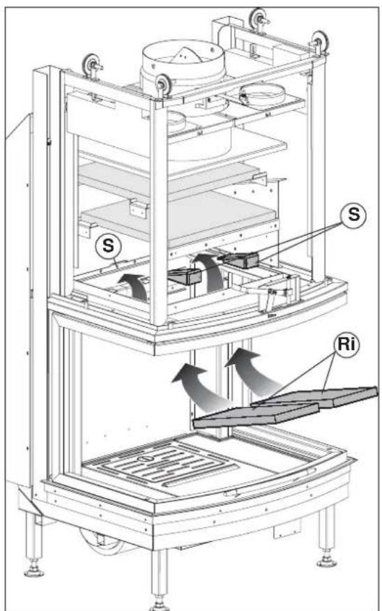
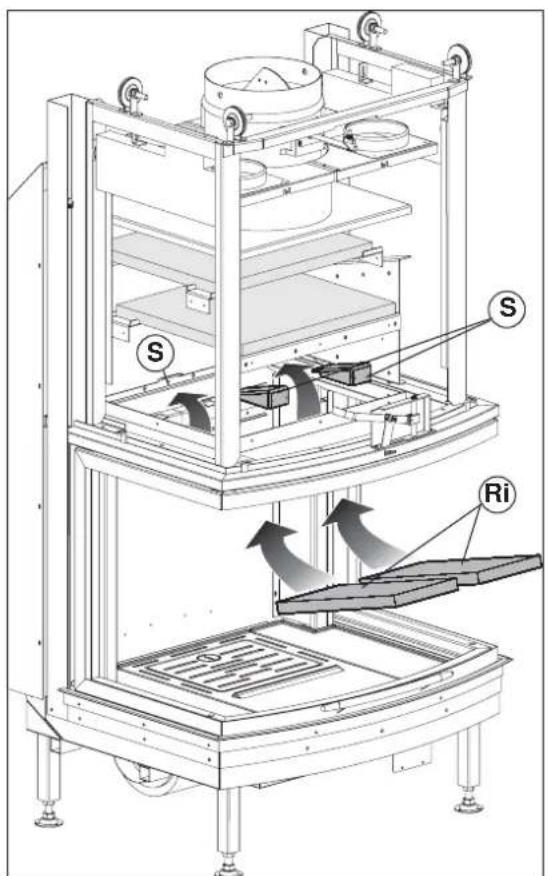
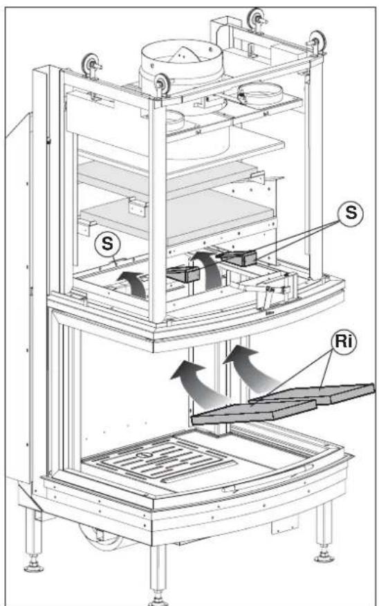
- insert the two lower refractory diaphragms (Ri) passing them through the hood, and then lodging them in the appropriate housings(S), Fig. 8.9.
-8.8-
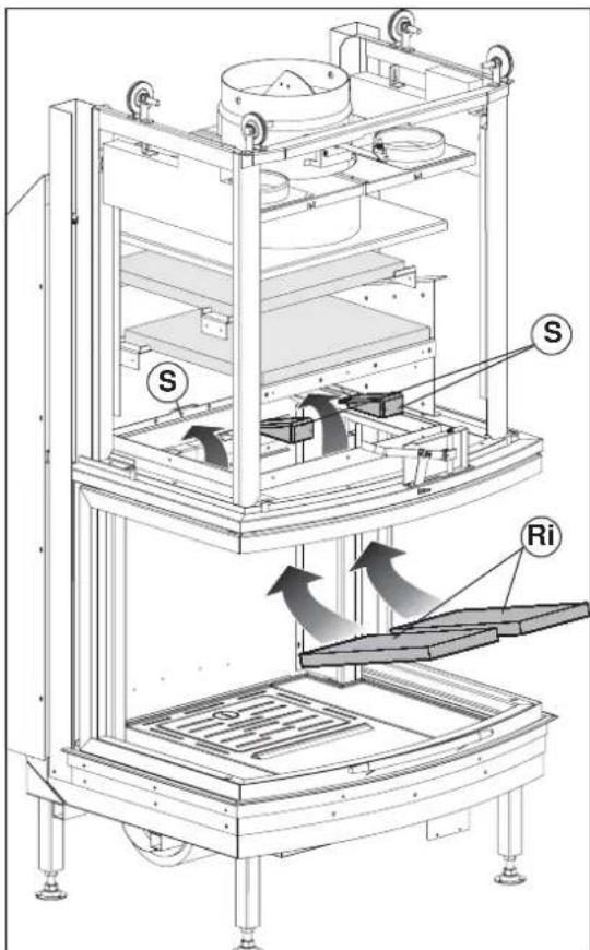
-8.9-
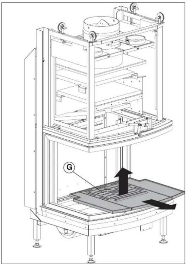
-8.10-
For the 3D versions S78 and S66:
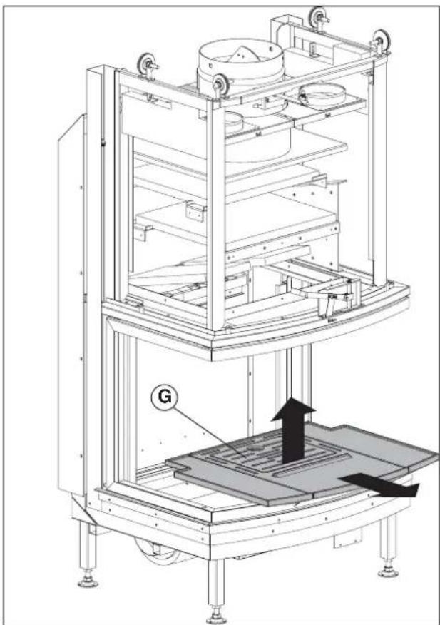
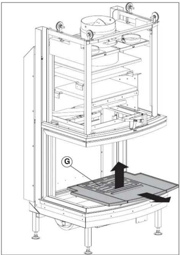
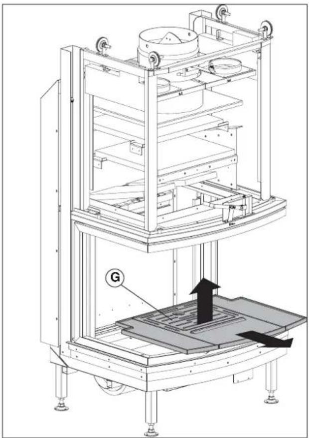
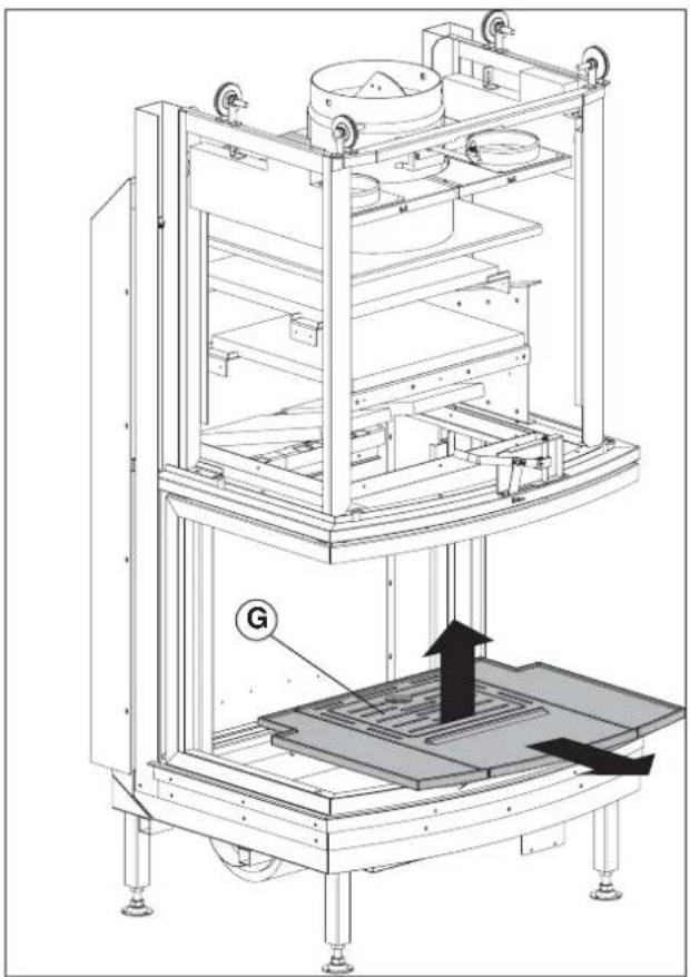
- Remove the cast iron parts (G) from the firebox (fig. 8.10).
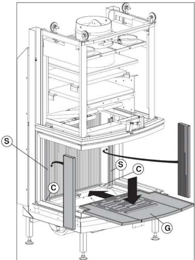
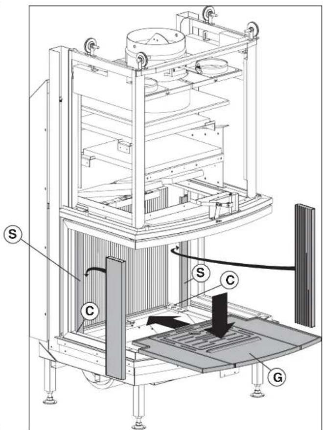
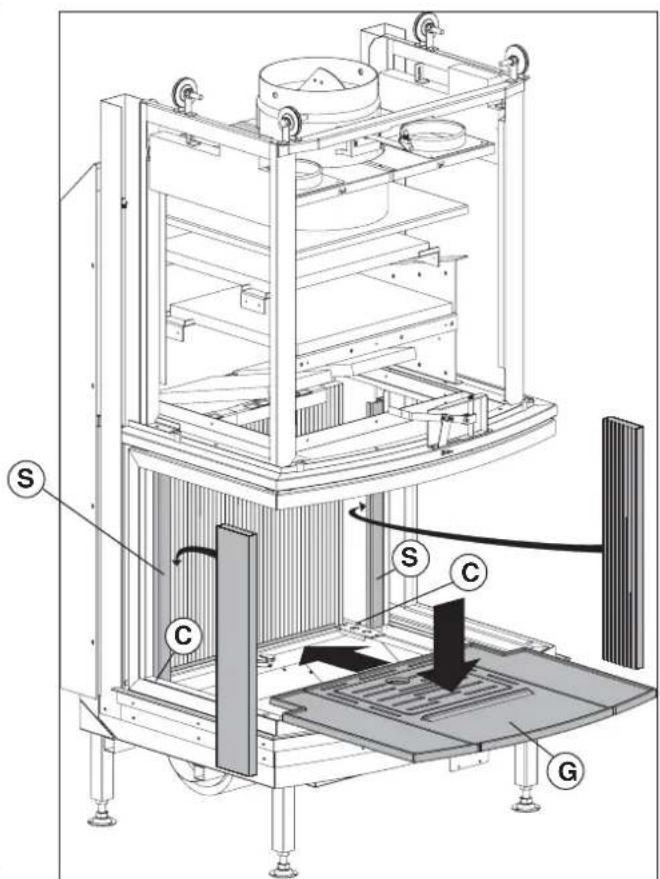
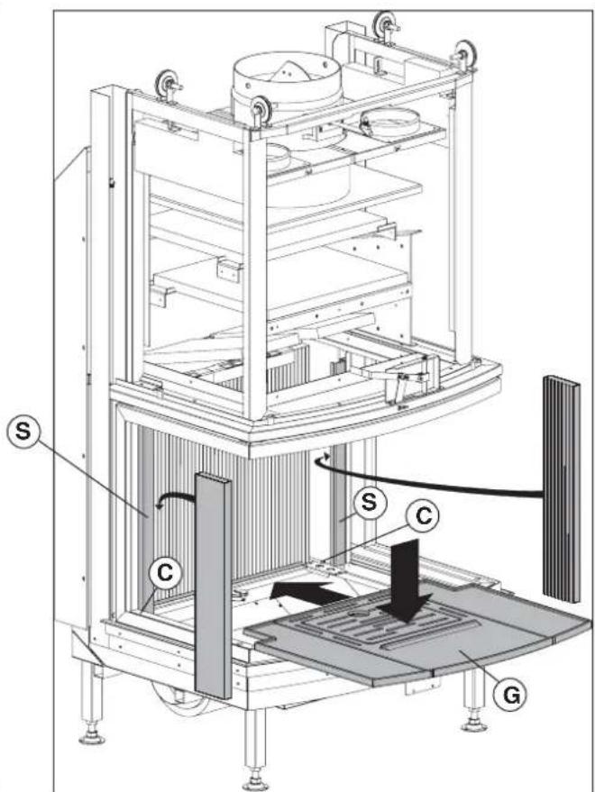
- Position the rear refractory in the cavity (C) and block it in place using the bracket (S) (Fig. 8.11, 8.9).
- Insert the lateral refractories on the right and left of the firebox, positioning them by rotating them into the appropriate housings (S), lodging them in the cast iron groove (C) (fig. 8.12).
- Reposition the cast iron parts (G) in the firebox (fig. 8.12).
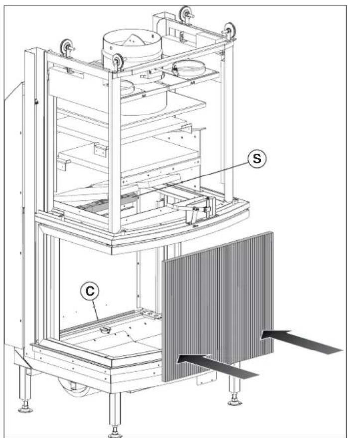
-8.11-
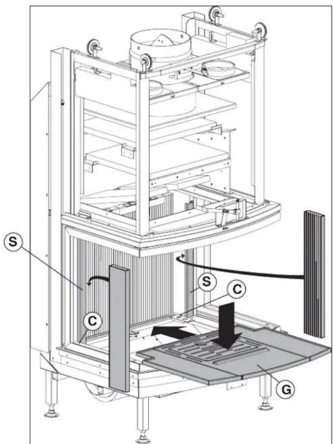
-8.12-
FOR 16: 9 3D MODEL:
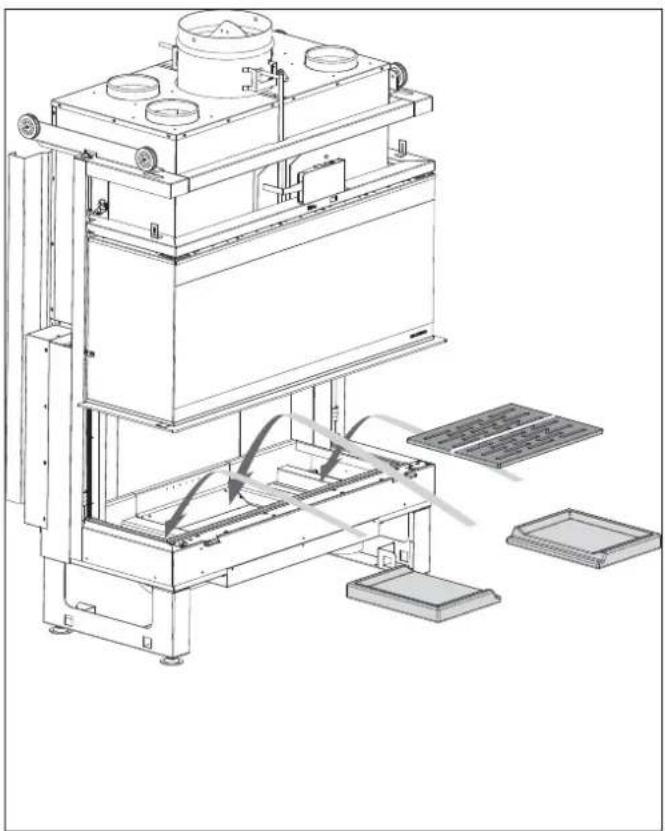
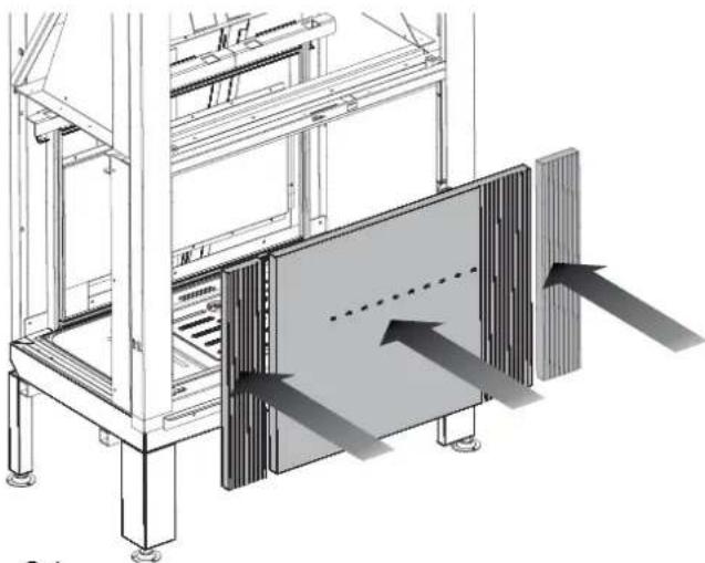
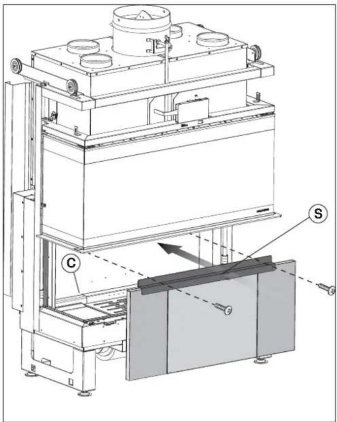
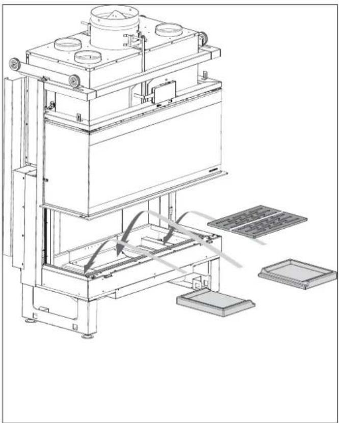
- Insert the upper baffles from the top down by placing them on their specific brackets (fig. 8.13).
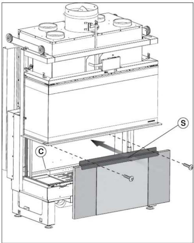
- Place the refractory panels on the back wall in the slot (C) and lock it with the special bracket (S) (fig. 8.14).
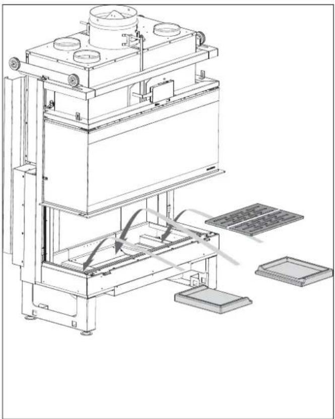
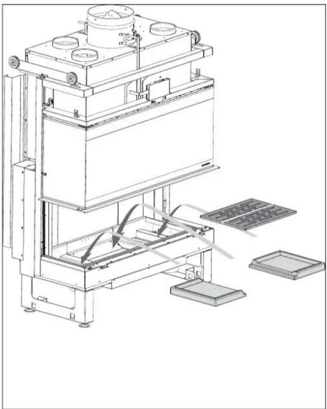
- Insert the two floors in refractory cement on both sides of the base and cast iron grate in the center (fig. 8.15).
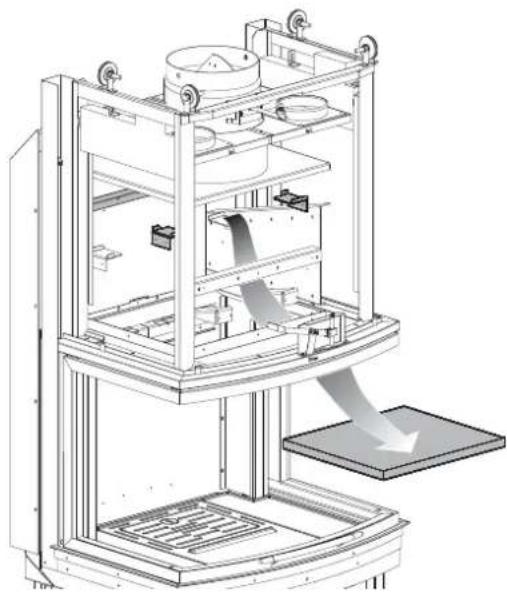
Place the fireproof panel supplied under the stove to protect the floor.
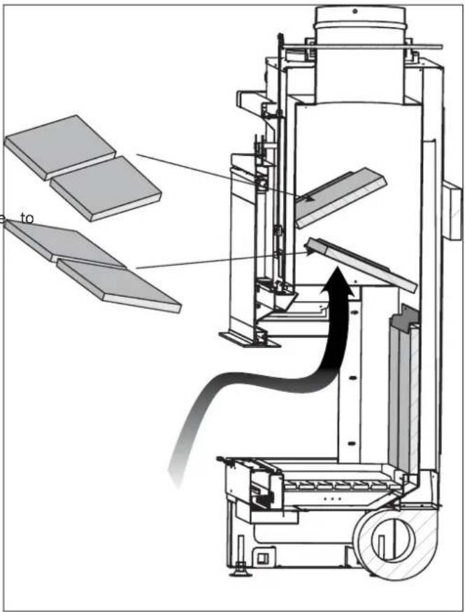
-8.13-
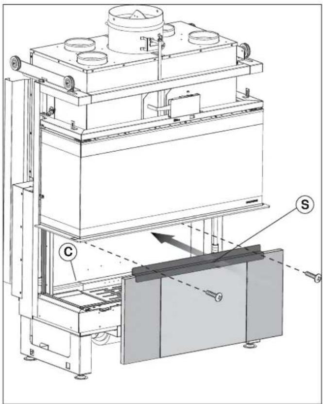
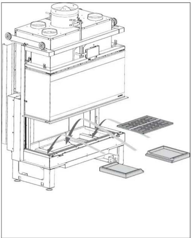
-8.15--8.14-
9 COMMISSIONING AND USING THE ECOMONOBLOCCO
9.1 DESCRIPTION OF THE PRODUCT
Before proceeding, check for any "specific features of the model" described for the Ecomonoblocco model in question in the enclosed "Product booklet".
9.2 LIGHTING THE STOVE FOR THE FIRST TIME
This recommended to do all manual operations using the glove provided.
LIGHT THE FIRE ONLY IN THE PROVIDED FIREWOOD HOLDER.
! The first ignition of the product (whether after installation or early season) must be made with reduced loads (\~ 2 kg / h) while the product is operating for at least 4 hours at low power. Proceed with these rhythms of charge for at least the next three days, before you can use the product to its full capacity. This will allow the evaporation of any moisture present in the firebox.
! When the stove is started the first time, unpleasant odours or smoke may be generated, caused by evaporation or drying of certain materials used. This phenomenon will gradually disappear.
The room should be well ventilated when starting the stove the first few times.
- Place rolled up balls of paper in the hearth, cover the paper with a small amount of twigs or fine pieces of old wood so that the fire takes nicely.
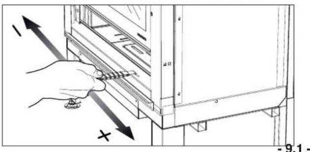
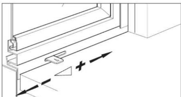
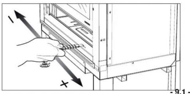
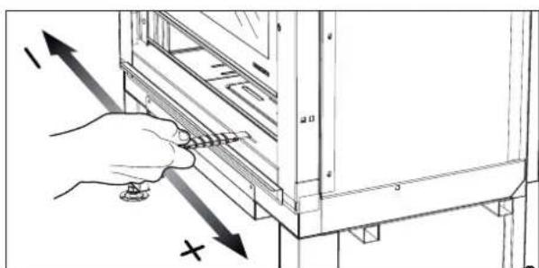
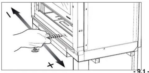
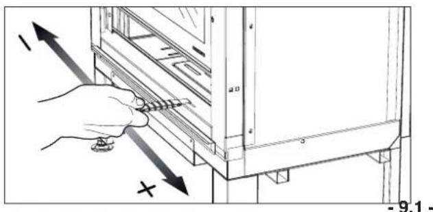
- Open the comburent air grid completely (Fig. 9.1: -CLOSED; +OPEN).
Light the paper and as the fire builds up add wood with approximately half the recommended quantity. As soon as the flames die down leaving a bed of ashes, load the fireplace with a normal amount of wood.
Never use alcohol, petrol, kerosene or other liquid fuels to light the fire. Keep these substances far away from the fire. Do not use petrol or chemical origin fire-lighters as they can seriously damage the hearth's walls. Only use ecological fire lighting aids.
When the appliance is working, possible inflammable materials must be placed at a distance of at least 170 cm from the radiation surface (glass sides of the hearth).
Do not touch the painted parts during first lightings to avoid damaging the paint finish and burn.
9.3 CONTROLLING COMBUSTION
PRIMARY COMBUSTION occurs by the intake of air into the fireplace, through the slits, adjusted using the knob located at the bottom right of the fireplace (Fig. 9.1):
- Moving the knob toward the + symbol, you have more rapid combustion;
- Moving the knob towards the - symbol, combustion will be slower.
Depending on time fro lighting greater will be the flame. For the first ignition of the day, or with damp wood, it is advisable to completely the primary air to the grate. Once the fire is burning it is advisable to adjust the air based on heating needs or how long you want the load of wood to last.
SECONDARY COMBUSTION, available on many Ecomonoblocco models, is obtained by placing preheated air in the fire box through the holes located in the upper part of the bottom wall. When it enters the fire box, the oxygen in the air ignites the unburned gases, especially the carbon monoxide, which formed during primary combustion, converting it to carbon dioxide. The effect is quite visible by the carpet of flame which forms where the secondary air inlet holes are located.
Secondary combustion, where available, is pre-calibrated and can only be activated when the fireplace is on and hot.
The fireplace is not suitable for continuous flame operation.
Check for any "specific features of the model" in the enclosed "product booklet".
9.4 HOW TO USE THE DOOR
The opening of the door is obtained by grasping the handle and pushing it up.
During operation of the fireplace it is required to keep the door completely lowered.
Fuel loading is to be carried out with the door completely open because any other intermediate positions may cause smoke to come out, or it may provoke a forge effect with violent combustion resulting in higher wood consumption. In case of abnormal functioning of the door, check the lifting mechanisms, accessing them through the inspection panel.
The sliding and lifting system of the door is handled by special sleeves that guarantee minimum friction and maximum silence. Once a year, make sure the system is working efficiently.
When the fire is lit, the door reaches very high temperatures.
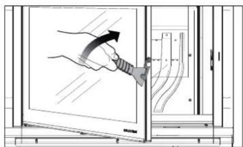
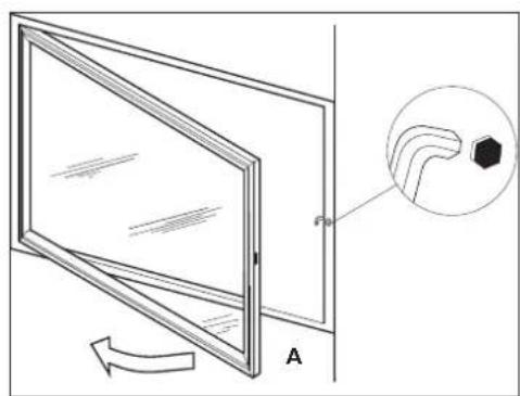
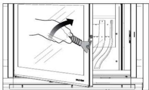
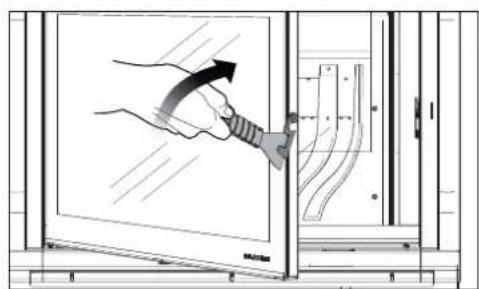
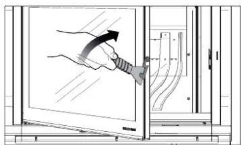
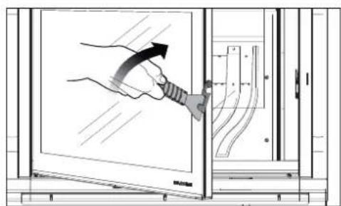
The door can be opened by swinging it out to clean the glass.
When loading wood into the fire box, door opening takes place in two steps:
- first slowly and partially (3-4 cm), to allow smoke from the fire box to be aspirated by the flue
- then completely, thus preventing smoke form coming out into the room.

Check for any "specific features of the model" in enclosed "product booklet".
9.5 SMOKE VALVE (VDF ® )
Ecomonoblocco models are equipped with the new control for the regulation of the quantity of combustion smoke outlet.
This adjustment makes it possible to control combustion by adjusting the draught based on installation conditions or atmospheric conditions.
The control also allows automatic opening of the smoke valve when the fire box door is lifted, thus preventing smoke form entering the room.
Normally, this adjustment is fixed and is performed when installing the fireplace.
Do not adjust the valve continuously. This does not control combustion.
9.6 OPERATION
The adjustment device lets you vary the position of the smoke valve from "fully closed" to "fully open" in an extremely gradual manner, thanks to the innovative micrometric selector.
To adjust the opening of the smoke valve turn the knurled knob to the left (closure) or to the right (opening). It will be possible to view the degree of opening on the graduated scale located to the left of the control (fig. 9.3).
Whatever adjustment is chosen, when the door of the fire box is lifted, the mechanism will automatically place the smoke valve in the "fully open" position, thus preventing smoke from getting into the room. When the door is closed again, the valve will again automatically return to the previously set position.

Check for any "specific features of the model" enclosed "product booklet".
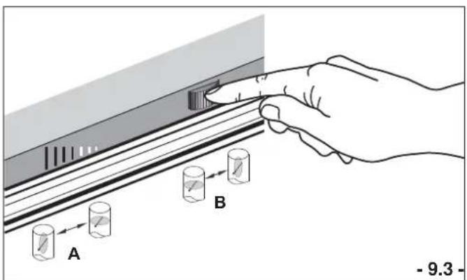
A- display of valve opening;
B- opening of valve in relation to the direction of rotation of the selector).
10 MAINTENANCE AND CLEANING
10.1 SAFETY PRECAUTIONS
Before carrying out any maintenance work, take the following precautions:
A) Ensure that all parts of the stove are completely cold.
B) Ensure that the ashes are completely out.
C) Use individual safety gear as set forth by directive 89/391/EEC.
D) Always use appropriate tools for maintenance.
10.2 CLEANING THE GLASS
To clean the internal surfaces of the glass, it is necessary to open the glass holding door as shown in the figure (Fig. 10.1):
- Clean the glass with a cloth or a damp roll of newspaper wiped in the ashes and then rubbed on the dirty parts until they are completely clean.
- Only carry out cleaning when the appliance is off and has cooled down.
- Do not lean on the door
- Pyroceram resists high temperatures very well, but it is fragile, so DO NOT STRIKE IT.
10.3 CLEANING THE FIRE BOX AND ASH BOX
The internal ash box (where provided) is spacious and easy to extract.
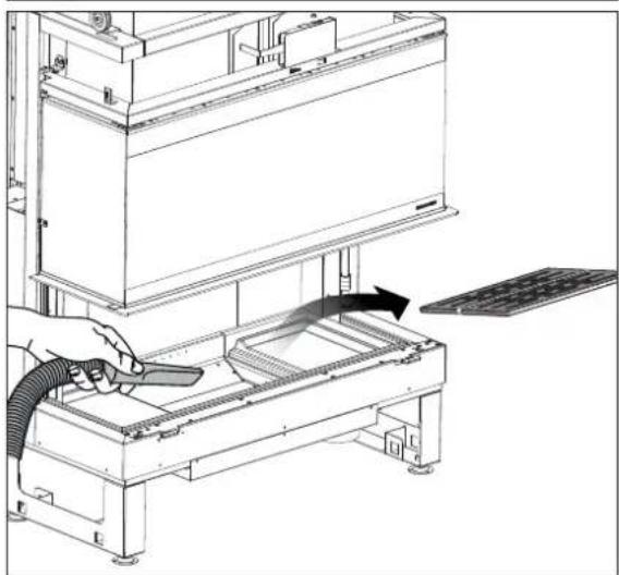
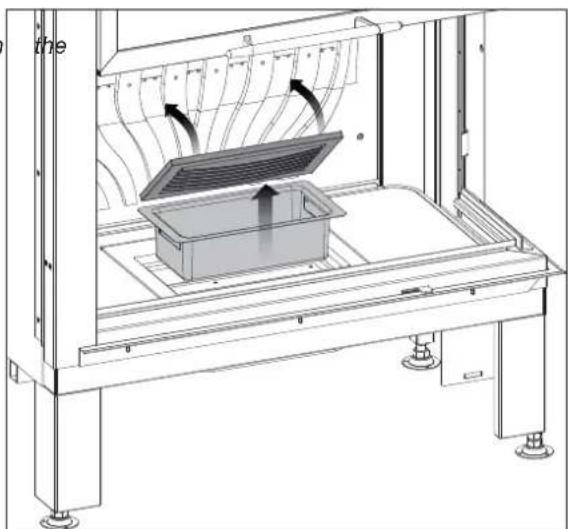
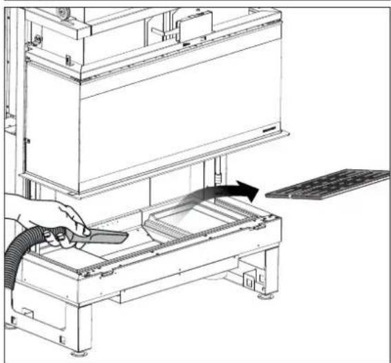
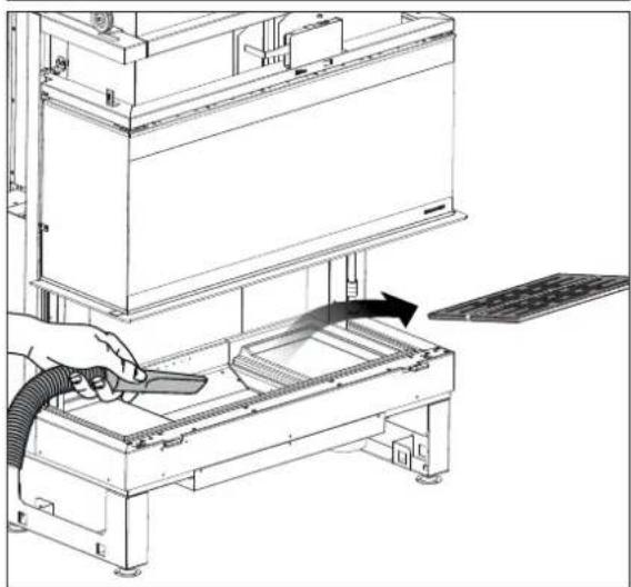
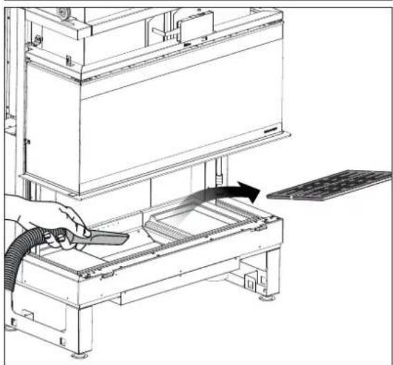
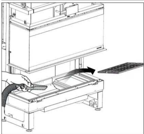
It is advisable to empty the ash box frequently to allow combustion air to get into the fire box. To empty the ash box, remove the grille located at the centre of the base of the firebox and extract the (Fig. 10.2).

Before carrying out this operation, make sure that the fireplace has cooled completely and make sure that are no burning embers in the ash box.
Warning: the ash may contain hot coals even after several hours.
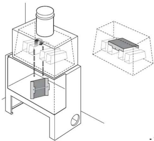
At least once a year, remove the smoke deflecto then clean thoroughly with a brush or appropriate tool in the inside to the outlet conduit, V.D.F. butterfly and heat exchanger pipes.

Check for any "specific features of the model" enclosed "product booklet".

Check for any "specific features of the model" in enclosed "product booklet".
10.1 -
-10.2-
10.4 CLEANING THE FLUE PIPE
he cleaning of the flue pipe, for excellent draught, must be carried out before the period the fireplace will be used and any time you notice a build-up of soot and tar, which are highly flammable.
The flue is cleaned by removing the metal smoke deflector (Fig 10.3) on cast-iron fireplaces, or the top panels on Magnofix fireplaces.
Incrustations, once they reach a thickness of 5-6 mm, in the presence of high temperatures and sparks may catch fire resulting in easily imaginable consequences for both the flue pipe and the dwelling.

It is therefore advisable to carry out cleaning at least once a year. Contact specialized personnel for this.

Check for any "specific features of the model" in the enclosed "product booklet".
11 INFORMATION FOR DEMOLITION
AND DISPOSAL
Demolition and disposal of the stove is the sole responsibility of the owner.
Dismantling and disposal may be entrusted to a third party provided we are talking about a company authorised to salvage and eliminate said materials.
In all cases you must abide by the laws in force in the country of installation as regards the disposal of materials and, if necessary, the report of disposal.
All dismantling operations for demolition must take place when the stove is at a standstill.
- contact the local authorised waste disposal company to scrap the stove structure.
Dumping the stove in accessible areas is a serious hazard for both people and animals.
he owner is always responsible for injury to people and animals.
When the stove is demolished, the EC mark, this manual and all the other documents relative to the stove must be destroyed.
-10.3-
INHALT
1 EINLEITUNG
6 INSTALLATION
6.1 MONTAGESCHEMA
←→=170cm
-6.2-

6.2 ERDUNG
-6.5-
BERATUNG:
-6.9a-
-6.9b-
-6.10-
-6.12-
6.8 GEGENHAUBE UND INSPEKTIONSPANEEL
-6.13-
-6.14-
-6.15-
7 ZUSÄTZLICH
7.1 KIT SCINTILLA(NUR FÜR BESTIMMTE MODELLE)
-8.1-
-8.2-
-8.3.1-
8 INSTALLATION DER MAGNOFIX PLATTEN
-8.3.2-
-8.4-
-8.5-
-8.6-
-8.7-
-8.8-
-8.9-
-8.10-
-8.11-
-8.12-
FÜR MODELL 16.9 3D:
-8.13-
-8.15--8.14-
-9.1-
9.5 VDF®-RAUCHVENTIL
10.1 -
-10.2-
INDEX
1 PREMESSA
1.1 SYMBOLES UTILISÉS DANS LE MANUEL
1.2 UTILISATION PRÉVUE
1.3 BUT ET CONTENU DU MANUEL
1.4 CONSERVATION DU MANUEL
1.5 MISE À JOUR DU MANUEL
1.6 INFORMATIONS GÉNÉRALES
1.7 PRINCIPALES NORMES DE SÉCURITÉ RESPECTÉES ET À RESPECTER
1.8 GARANTIE LÉGALE
1.9 LIMITES DE RESPONSABILITÉ DU FABRICANT
1.10 CARACTÉRISTIQUES DE L'UTILISATEUR
1.11 ASSISTANCE TECHNIQUE
1.12 PIÈCES DÉTACHÉES
1.13 PLAQUE D'IDENTIFICATION
1.14 LIVRAISON DU FOYER
10 ENTRETIEN ET NETTOYAGE
10.1 RECOMMANDATIONS DE SÉCURITÉ
10.2 NETTOYAGE DE LA VITRE
10.3 NETTOYAGE DU FOYER ET DU TIROIR À CENDRE
10.4 RAMONAGE DU CONDUIT DE FUMÉE
11 INFORMATIONS POUR LA DÉMOLITION ET L'ÉLIMINATION
2 CONSIGNES DE SÉCURITÉ
2.1 CONSIGNES POUR L'INSTALLATEUR
2.2 CONSIGNES POUR L'UTILISATEUR
2.3 CONSIGNES POUR LE RESPONSABLE DE L'ENTRETIEN
3 DÉPLACEMENT ET TRANSPORT
4 TYPE DE COMBUSTIBLE
5 PRÉPARATION
DU
LIEU
D'INSTALLATION
5.1 PRÉCAUTIONS POUR LA SÉCURITÉ
5.2 INSTALLATION À BLANC
6 INSTALLATION
6.1 SCHÉMA DE MONTAGE
6.2 MISE À LA TERRE
6.3 RÉGLAGE DE LA HAUTEUR
6.4 SYSTEME D'EVACUATION DES FUMEES
6.5 RACCORDEMENT AU CONDUIT DE FUMÉE
6.6 BRANCHEMENT À L'ARRIVÉE D'AIR
6.7 RACCORDEMENT BOUCHES DE SORTIE AIR CHAUD
6.8 CONTRE-HOTTE ET TRAPPE DE VISITE
7 OPTION
7.1 KIT SCINTISEALEMENT POUR CERTAINS
MODELES)
7.2 RINGO
7.3 MANCHON AIR DE COMBUSTION
7.4 VENTILATEUR AVEC BOÎTIER CENTRALE DE COMMANDE EXTÉRIEUR
8 MONTAGE PLAQUES REFRACTAIRES
9 MISE EN SERVICE ET UTILISATION
9.1 DESCRIPTION DU PRODUIT
9.2 PREMIER ALLUMAGE
9.3 CONTRÔLE DE LA COMBUSTION
9.4 COMMENT UTILISER LA PORTE
9.5 CLAPET FUMÉES (VDF)
1 PREMESSA
-3.1-
5 PRÉPARATION DU LIEU D'INSTALLATION
5.1 PRÉCAUTIONS POUR LA SÉCURITÉ
6 INSTALLATION
6.1 SCHÉMA DE MONTAGE

-6.2-
-6.3a-

-6.3b-
6.2 MISE À LA TERRE
-6.5-
CONSEILS: CHEMINÉES, DISTANCES ET POSITIONNEMENT
6.5 RACCORDEMENT AU CONDUIT DE FUMÉE
-6.10-
-6.11-
-6.12-
6.8 CONTRE-HOTTE ET TRAPPE DE VISITE
-6.13-
-6.14-
-6.15-
7 OPTION
7.1 KIT SCINTILLA(SEULEMENT POUR CERTAINS MODELES)
-8.1-
-8.2-
-8.3.1-
8 MONTAGE PLAQUES REFRACTAIRES
-8.3.2-

-8.4-
-8.5-
-8.6-
-8.7-
-8.8-
-8.9-
-8.10-
-8.11-
-8.12-
POUR LE MODELE 16:9 3D:
-8.13-
-8.15--8.14-
9 MISE EN SERVICE ET UTILISATION
9.1 DESCRIPTION DU PRODUIT

9.4 COMMENT UTILISER LA PORTE
10.1 -
10.3 NETTOYAGE DU FOYER ET DU TIROIR À CENDRE
-10.2-
10.4 RAMONAGE DU CONDUIT DE FUMÉE
ÍNDICE
-3.1-
6 INSTALACIÓN
6.1 ESQUEMA DE MONTAJE
- 6.3a -
-6.3b-
-6.5-
ASESORAMIENTO
CHIMENEAS, DISTANCIAS Y POSICIONAMIENTO:
-6.10-
-6.11-
-6.12-
-6.13-
-6.14-
-6.15-
7 OPCIONALES
7.1 KIT "SCINTILLA (SÓLO EN CIERTOS MODELOS)
-8.1-
-8.2-
-8.3.1-
8 MONTAJE PLACAS DE REFRACTARIO
-8.3.2-
-8.4-
Modelo Sedici Noni CX, Venticinque Noni, Venticinque Noni doble cara solamente:
-8.5-
-8.6-
-8.7-
Solo modelo S78 3D:
-8.8-
-8.9-
-8.10-
SOLO modelo S78 3D:
-8.11-
-8.12-
POR EL MODELO 16:9 3D:
-8.13-

-8.15--8.14-
9 PUESTA EN MARCHA Y USO
9.4 CÓMO SE USA LA PUERTA
- 10.1 -
10.3 LIMPIEZA DEL HOGAR Y DEL CAJÓN DE LA CENIZA
-10.2-
PALAZZETTI
IL CALORE CHE PIACE ALLA NATURA
Palazzetti Lelio s.p.a.
Via Roveredo, 103
cap 33080 - Porcia (PN) - ITALY
Internet: www.palazzetti.it
Palazzetti accepts no liability for any mistakes in this handbook and is free to modify the features of its products without prior notice.
- IT
- GB
- DE
- 8 MONTAGGIO REFRATTARI
- 9 MESSA IN SERVIZIO ED USO
- 6 INSTALLAZIONE
- 6.1 SCHEMA DI MONTAGGIO
- 6.2 MESSA A TERRA
- 7 OPTIONAL
- 7.1 KIT SCINTILL®(SOLO PER I MODELLI PREDISPOSTI)
- SOLO MODELLI VENTICINQUE NONI
- PER I MODELLI S78 3D E S66 3D
- PER I MODELLI 16:9 3D
- 9.2 PRIMA ACCENSIONE
- 9.4 COME USARE LA PORTINA
- 10.3 PULIZIA DEL FOCOLARE E CASSETTO CENERE
- 10.4 PULIZIA DEL CAMINO
- INDEX
- 2 SAFETY PRECUATIONS
- 3 HANDLING AND TRANSPORT
- 4 TYPE OF FUEL
- 5 PREPARING THE PLACE OF INSTALLATION
- 6 INSTALLATION
- 8 INSTALLATION OF THE REFRACTORY PARTS
- 9 COMMISSIONING AND USING THE ECOMONOBLOCCO
- 1 GENERAL
- 1.1 SYMBOLS
- 1.2 INTENDED USE
- 1.3 PURPOSE AND CONTENTS OF THE MANUAL
- PURPOSE
- CONTENTS
- 1.4 KEEPING THE MANUAL
- KEEPING AND CONSULTING THE MANUAL
- DETERIORATION OR LOSS
- SELLING THE FIREPLACE
- 1.5 MANUAL UPDATE
- 1.6 GENERAL INFORMATION
- INFORMATION
- LIABILITIES
- EXTRAORDINARY MAINTENANCE
- RESPONSIBILITY FOR INSTALLATION
- USE
- 1.7 MAIN ACCIDENT PREVENTION REGULATIONS TO COMPLY WITH
- 1.8 LEGAL GUARANTEE
- 1.9 MANUFACTURER'S LIABILITY
- 1.10 USER CHARACTERISTICS
- 1.11 TECHNICAL ASSISTANCE
- 1.12 SPARE PARTS
- 1.13 ID PLATE
- 1.4 DELIVERY OF THE FIREPLACE
- 2.1 INSTRUCTIONS FOR THE INSTALLER
- 2.2 INSTRUCTIONS FOR THE USER
- 2.3 PRECAUTIONS FOR THE MAINTENANCE ENGINEER
- 5.1 SAFETY PRECAUTIONS
- 5.2 DRY POSITIONING
- 5.2.1 SAFETY RECOMMENDATIONS
- 6.1 ASSEMBLY DIAGRAM
- 6.2 EARTHING
- 6.3 HEIGHT ADJUSTMENT
- 6.4 SMOKE EXHAUST SYSTEM
- DOUBLE THE INTERNAL ONE OF THE FLUE
- CONSIGLI RECOMMENDATIONS - BERATUNG
- 6.5 CONNECTION TO FLUE PIPE
- 6.6 AIR INTAKE CONNECTION
- 6.6.1 COMBUSTION AIR INTAKE
- 6.7 HOT AIR DELIVERY CONNECTION
- 6.7.1 CONNECTION IN COUNTER-HOOD FOR SINGLE-ROOM HEATING
- 6.7.2 CONNECTION TO DUCTING FOR MULTI-ROOM HEATING
- AIR DUCTING DIAGRAM (FIG. 6.12)
- 6.8 COUNTER-HOOD AND INSPECTION PANEL
- 6.8.1 INSPECTION PANEL INSTALLATION AND VDF ADJUSTMENT
- 7.1 KIT SCINTILL®(ONLY FOR CERTAIN MODELS)
- 7.2 RONG ®
- 7.3 COMBUSTION AIR INTAKE
- 7.4 FAN WITH EXTERNAL CONTROL UNIT
- 7.4.1 ELECTRIC FAN CONNECTION (OPTIONAL)
- ON ECOMONOBLOCCO MODELS WITH SMALLER FEET, THIS SOLUTION IS ONLY POSSIBLE BY INSTALLING THE EXTENSION LEG KIT
- IF INSTALLATION IS PERFORMED AS SHOWN IN FIGURE 5.8B, MAKE SURE THERE IS A DISTANCE OF AT LEAST 50 CM BETWEEN THE COMBUSTION AIR INTAKE AND THE FAN INTAKE
- MODELS VENTICINQUE NONI ONLY
- FOR THE 3D VERSIONS S78 AND S66
- FOR 16: 9 3D MODEL
- 9.1 DESCRIPTION OF THE PRODUCT
- 9.2 LIGHTING THE STOVE FOR THE FIRST TIME
- LIGHT THE FIRE ONLY IN THE PROVIDED FIREWOOD HOLDER
- 9.3 CONTROLLING COMBUSTION
- 9.4 HOW TO USE THE DOOR
- 9.5 SMOKE VALVE (VDF ® )
- 9.6 OPERATION
- 10 MAINTENANCE AND CLEANING
- 10.1 SAFETY PRECAUTIONS
- 10.2 CLEANING THE GLASS
- 10.3 CLEANING THE FIRE BOX AND ASH BOX
- 10.4 CLEANING THE FLUE PIPE
- 11 INFORMATION FOR DEMOLITION
- AND DISPOSAL
- INHALT
- 1 EINLEITUNG
- 6.1 MONTAGESCHEMA
- 6.2 ERDUNG
- 6.8 GEGENHAUBE UND INSPEKTIONSPANEEL
- 7 ZUSÄTZLICH
- 7.1 KIT SCINTILLA(NUR FÜR BESTIMMTE MODELLE)
- 8 INSTALLATION DER MAGNOFIX PLATTEN
- FÜR MODELL 16.9 3D
- 9.5 VDF®-RAUCHVENTIL
- 1 PREMESSA
- 10 ENTRETIEN ET NETTOYAGE
- 11 INFORMATIONS POUR LA DÉMOLITION ET L'ÉLIMINATION
- 2 CONSIGNES DE SÉCURITÉ
- 3 DÉPLACEMENT ET TRANSPORT
- 4 TYPE DE COMBUSTIBLE
- 5 PRÉPARATION
- 7 OPTION
- 8 MONTAGE PLAQUES REFRACTAIRES
- 9 MISE EN SERVICE ET UTILISATION
- 5 PRÉPARATION DU LIEU D'INSTALLATION
- 5.1 PRÉCAUTIONS POUR LA SÉCURITÉ
- 6.1 SCHÉMA DE MONTAGE
- 6.2 MISE À LA TERRE
- 6.5 RACCORDEMENT AU CONDUIT DE FUMÉE
- 6.8 CONTRE-HOTTE ET TRAPPE DE VISITE
- 7.1 KIT SCINTILLA(SEULEMENT POUR CERTAINS MODELES)
- POUR LE MODELE 16:9 3D
- 9.1 DESCRIPTION DU PRODUIT
- 9.4 COMMENT UTILISER LA PORTE
- 10.3 NETTOYAGE DU FOYER ET DU TIROIR À CENDRE
- 10.4 RAMONAGE DU CONDUIT DE FUMÉE
- ÍNDICE
- 6 INSTALACIÓN
- 6.1 ESQUEMA DE MONTAJE
- ASESORAMIENTO
- 7 OPCIONALES
- 7.1 KIT "SCINTILLA (SÓLO EN CIERTOS MODELOS)
- 8 MONTAJE PLACAS DE REFRACTARIO
- MODELO SEDICI NONI CX, VENTICINQUE NONI, VENTICINQUE NONI DOBLE CARA SOLAMENTE
- SOLO MODELO S78 3D
- POR EL MODELO 16:9 3D
- 9 PUESTA EN MARCHA Y USO
- 9.4 CÓMO SE USA LA PUERTA
- 10.3 LIMPIEZA DEL HOGAR Y DEL CAJÓN DE LA CENIZA
- PALAZZETTI
Brand : Palazzetti
Model : Ecomonoblocco EM16:9 3D
Category : Frying Pan