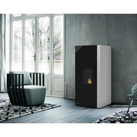
Ecofire Dadò Idro 10 - Frying Pan Palazzetti - Free user manual and instructions
Find the device manual for free Ecofire Dadò Idro 10 Palazzetti in PDF.


| Product type | Hydraulic pellet stove |
| Brand | Palazzetti |
| Model | Ecofire Dadò Idro 10 |
| Total thermal output | 4.6 - 10.3 kW |
| Water thermal output | 3.9 - 9.5 kW |
| Efficiency | 96% |
| Hourly pellet consumption | 1 - 2.23 kg/h |
| Hopper capacity | 45 kg |
| Estimated autonomy | Up to 20 h at minimum power |
| Flue gas temperature | 59.3 - 78 °C |
| CO emissions (at 13% O2) | 82 - 276 mg/Nm³ |
| Flue outlet diameter | 80 mm |
| Combustion air inlet diameter | 60 mm |
| External air intake diameter | 100 mm |
| Required draft | 12 ± 2 Pa |
| Minimum room volume | 40 m³ |
| Maximum operating pressure | 2.5 bar |
| Boiler water content | 42.3 L |
| Power supply | 220-240 V, 50 Hz |
| Power consumption (operation) | 45 W |
| Power consumption at ignition | 360 W |
| Dimensions (H x W x D) | 1341 x 615 x 604 mm |
| Weight | 223 kg |
| Fuel | Wood pellets |
| Hydraulic connection | 3/4" male gas pipes (supply and return) |
| Routine maintenance | Weekly cleaning of burner and ash pan |
| Chimney sweeping frequency | Annual (mandatory) |
| Safety | Thermal safety, pressure safety, electronic ignition |
| Warranty | 2 years |
Frequently Asked Questions - Ecofire Dadò Idro 10 Palazzetti
User questions about Ecofire Dadò Idro 10 Palazzetti
0 question about this device. Answer the ones you know or ask your own.
Ask a new question about this device
Download the instructions for your Frying Pan in PDF format for free! Find your manual Ecofire Dadò Idro 10 - Palazzetti and take your electronic device back in hand. On this page are published all the documents necessary for the use of your device. Ecofire Dadò Idro 10 by Palazzetti.
USER MANUAL Ecofire Dadò Idro 10 Palazzetti
natural_image
Technical line drawing of an electrical enclosure or enclosure with internal components and mounting brackets (no text or symbols)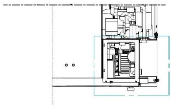
natural_image
Architectural floor plan showing room layouts and staircases (no text or labels)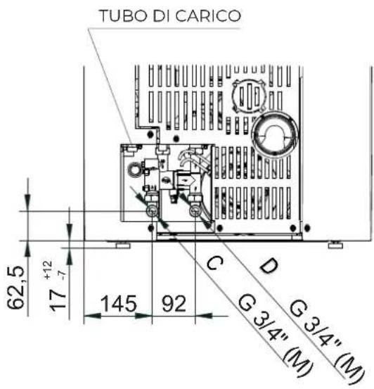
Fig. 2
D
natural_image
Technical line drawing of a computer tower case with visible internal components and mounting holes (no text or labels)Fig. 3
natural_image
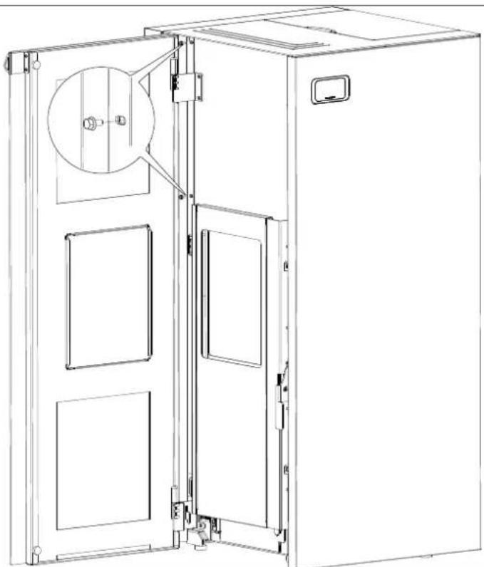
Technical line drawing of a double door with internal compartments and mounting brackets (no text or symbols)Fig. 4
natural_image
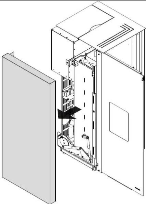
Technical line drawing of an open industrial machine with internal components and a door panel (no text or symbols)Fig. 5
natural_image
Technical line drawing of a server rack unit with internal panel and ventilation slots (no text or labels)Fig. 6
natural_image
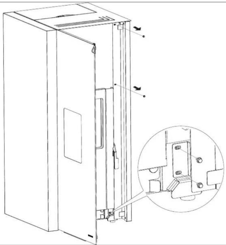
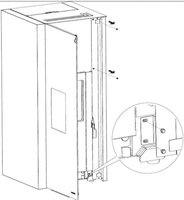
Technical line drawing of a door frame with an inset close-up showing internal components (no text or symbols)Fig. 7
natural_image
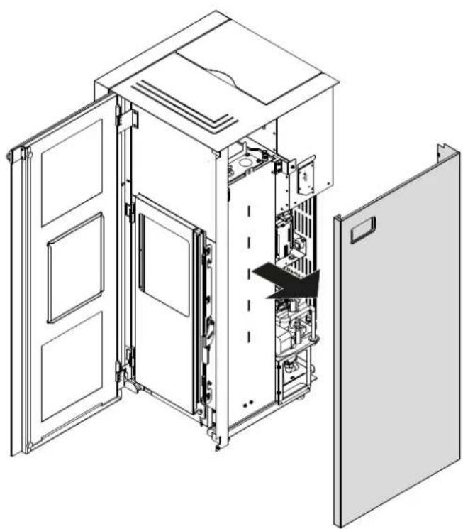
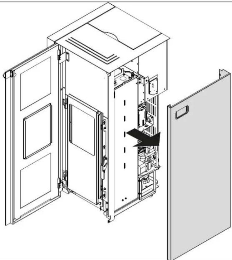
Technical line drawing of an open industrial refrigerator with internal compartments and door opening (no text or symbols)Fig. 8
natural_image
Technical line drawing of an internal server unit with visible internal components and ventilation slots (no text or labels)Fig. 9
1.1 Technical features 17
2 DISASSEMBLY AND ASSEMBLY OF PANELS 21
2.1 Disassembly of left side panel 21
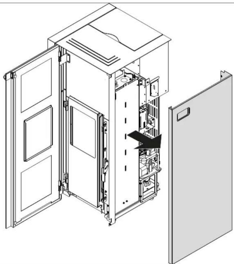
2.2 Disassembly of right side panel 22
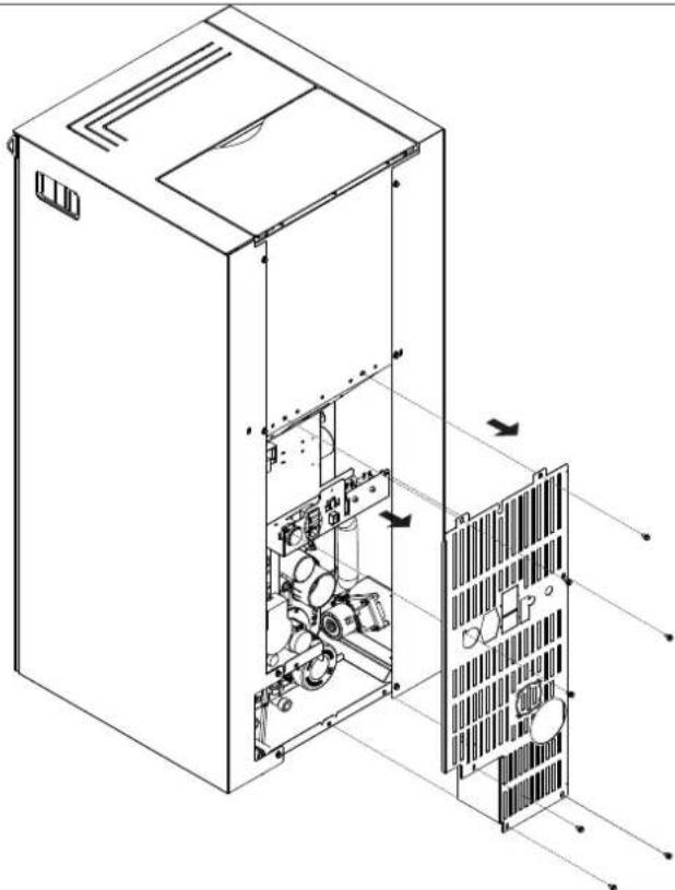
2.3 Disassembly of back panel 24
1 GENERAL DESCRIPTION
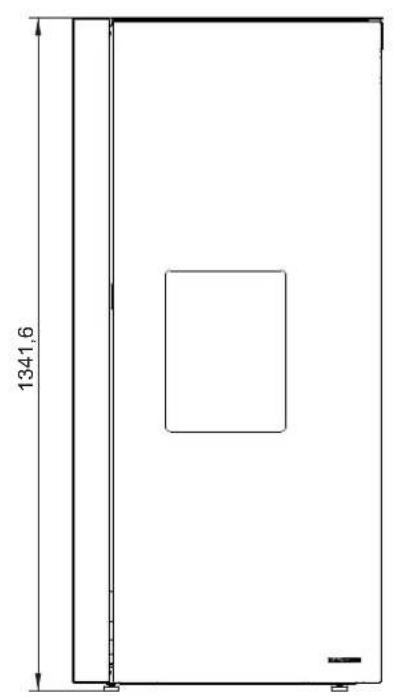
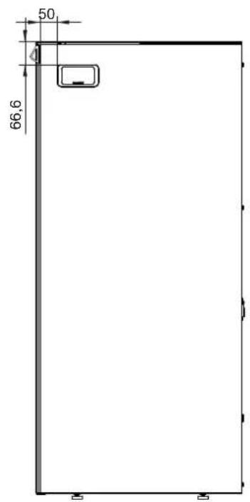
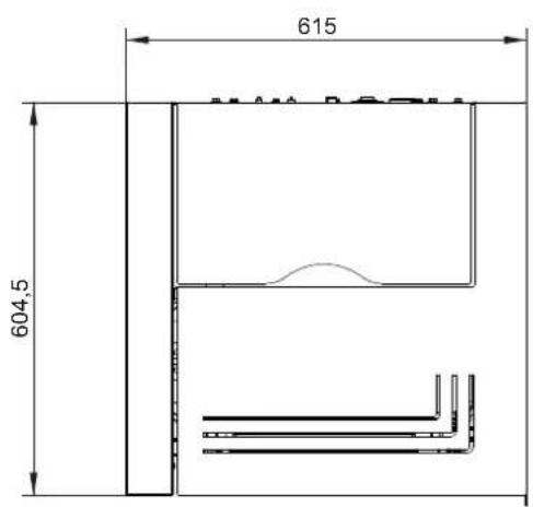
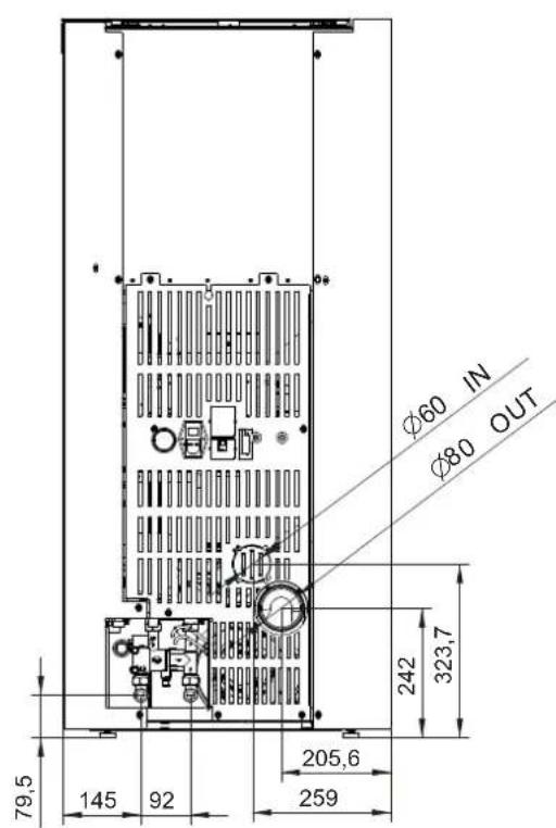
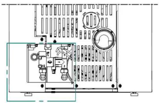
Fig.1
natural_image
Technical line drawing of an electronic device interior with circuitry and mounting points (no text or symbols)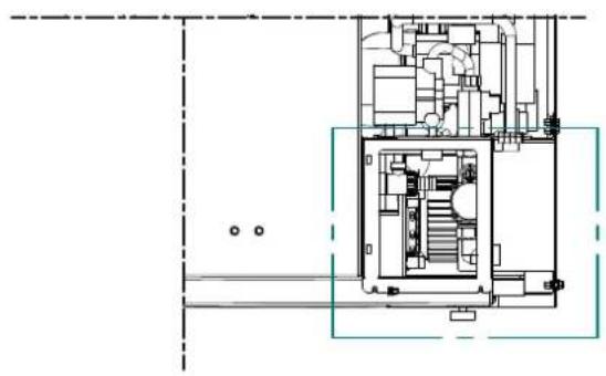
natural_image
Architectural floor plan showing room layouts and structural elements (no text or labels)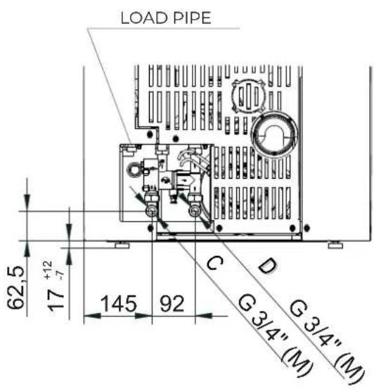
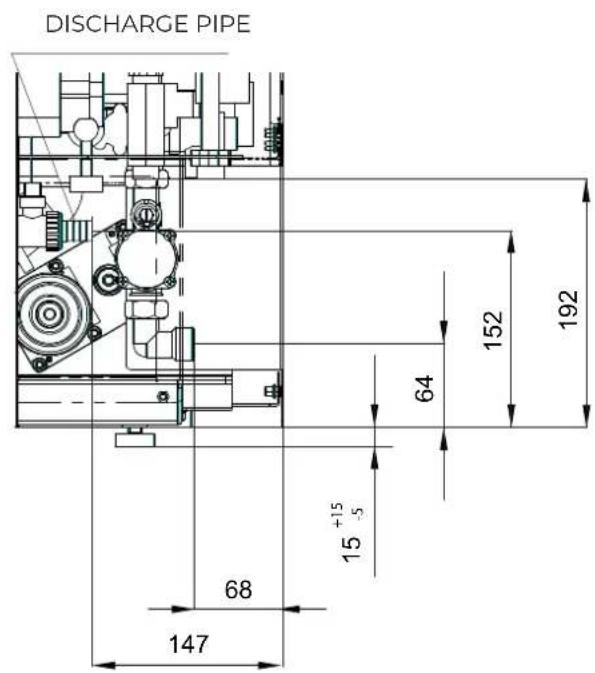
Fig. 2
D Flow pipe (3/4' gas M)
C Return pipe (3/4' gas M)
1.1 Technical features
| ECOFIRE DADÒ | IDRO 10 | ||
| Min Max | |||
| Overall thermal power (output) kW 4.6 10.3 | |||
| Thermal power to water kW 3.9 9.5 | |||
| Yield % 96.4 96 | |||
| Flue gas temperature | °C | 59.3 | 78 |
| Flue gas flow rate | g/s | 4.56 | 7.11 |
| Hourly fuel consumption | kg/h | 1 | 2.23 |
| Emissions of CO (at 13% of O2) | mg/Nm3 | 276 | 82 |
| Flue gas outlet | mm | ∅ 80 | |
| Combustion air inlet | mm | ∅ 60 | |
| Outside air intake | mm | ∅ 100 | |
| Fuel | Wooden pellets | ||
| Flue draught | Pa | 12 ± 2 | |
| Minimum draught for chimney sizing | Pa | 0.0 | |
| Stove suitable for rooms no smaller than | m3 | 40 | |
| Feeding tank capacity | kg | 45 | |
| Weight | kg | 223 | |
| No. of room fans | no. | - | |
| Room fan flow rate | m3/h | - | |
| Maximum operating pressure | bar 2.5 (200000 Pa) | ||
| Water content in the boiler | litres | 42.3 | |
| Electrical data | DADÔ 10 | ||
| Voltage V 220-240 | |||
| Frequency | Hz | 50 | |
| Max power absorbed during operation W | 45 | ||
| Power absorbed at electric ignition | W | 360 | |
| ECOFIRE DADÒ | IDRO 15 | ||
| Min Max | |||
| Overall thermal power (output) kW 4.6 15 | |||
| Thermal power to water kW 3.9 14.1 | |||
| Yield % 96.4 95.3 | |||
| Flue gas temperature °C 59.3 95.6 | |||
| Flue gas flow rate | g/s | 4.56 | 9.43 |
| Hourly fuel consumption | kg/h | 1 | 3.27 |
| Emissions of CO (at 13% of O2) | mg/Nm ^3 | 276 | 58 |
| Flue gas outlet | mm | ∅ 80 | |
| Combustion air inlet | mm | ∅ 60 | |
| Outside air intake | mm | ∅ 100 | |
| Fuel | Wooden pellets | ||
| Flue draught | Pa | 12 ± 2 | |
| Minimum draught for chimney sizing | Pa | 0.0 | |
| Stove suitable for rooms no smaller than m | ^3 | 40 | |
| Feeding tank capacity | kg | 45 | |
| Weight | kg | 223 | |
| No. of room fans | no. | - | |
| Room fan flow rate | m ^3 /h | - | |
| Maximum operating pressure | bar | 2.5 (200000 Pa) | |
| Water content in the boiler | litres | 42.3 | |
| Electrical data | DADÔ 15 | ||
| Voltage V 220-240 | |||
| Frequency | Hz | 50 | |
| Max power absorbed during operation | W | 45 | |
| Power absorbed at electric ignition | W | 360 | |
| ECOFIRE DADÒ | IDRO 20 | ||
| Min Max | |||
| Overall thermal power (output) kW 4.6 20 | |||
| Thermal power to water kW 3.9 18.9 | |||
| Yield % 96.4 94.7 | |||
| Flue gas temperature | °C | 59.3 | 114.4 |
| Flue gas flow rate | g/s | 4.56 | 11.28 |
| Hourly fuel consumption | kg/h | 1 | 4.39 |
| Emissions of CO (at 13% of O2) | mg/Nm3 | 276 | 66 |
| Flue gas outlet | mm | ∅ 80 | |
| Combustion air inlet | mm | ∅ 60 | |
| Outside air intake | mm | ∅ 100 | |
| Fuel | Wooden pellets | ||
| Flue draught | Pa | 12 ± 2 | |
| Minimum draught for chimney sizing | Pa | 0.0 | |
| Stove suitable for rooms no smaller than | m3 | 40 | |
| Feeding tank capacity | kg | 45 | |
| Weight | kg | 223 | |
| No. of room fans | no. | - | |
| Room fan flow rate | m3/h | - | |
| Maximum operating pressure | bar | 2.5 (200000 Pa) | |
| Water content in the boiler | litres | 42.3 | |
| Electrical data | DADÒ 20 | ||
| Voltage V 220-240 | |||
| Frequency | Hz | 50 | |
| Max power absorbed during operation W | 45 | ||
| Power absorbed at electric ignition | W | 360 | |
| ECOFIRE DADÒ | IDRO 26 | ||
| Min Max | |||
| Overall thermal power (output) kW 4.6 26 | |||
| Thermal power to water kW 3.9 24.6 | |||
| Yield % 96.4 94 | |||
| Flue gas temperature °C 59.3 137 | |||
| Flue gas flow rate | g/s | 4.56 | 13.2 |
| Hourly fuel consumption | kg/h | 1 | 5.75 |
| Emissions of CO (at 13% of O2) | mg/Nm ^3 | 276 | 94 |
| Flue gas outlet | mm | ∅ 80 | |
| Combustion air inlet | mm | ∅ 60 | |
| Outside air intake | mm | ∅ 100 | |
| Fuel | Wooden pellets | ||
| Flue draught | Pa | 12 ± 2 | |
| Minimum draught for chimney sizing | Pa | 0.0 | |
| Stove suitable for rooms no smaller than m | ^3 | 40 | |
| Feeding tank capacity | kg | 45 | |
| Weight | kg | 223 | |
| No. of room fans | no. | - | |
| Room fan flow rate | m ^3 /h | - | |
| Maximum operating pressure | bar 2.5 (200000 Pa) | ||
| Water content in the boiler | litres | 42.3 | |
| Electrical data | DADÒ 26 | |
| Voltage V 220-240 | ||
| Frequency | Hz | 50 |
| Max power absorbed during operation W | 45 | |
| Power absorbed at electric ignition | W | 360 |
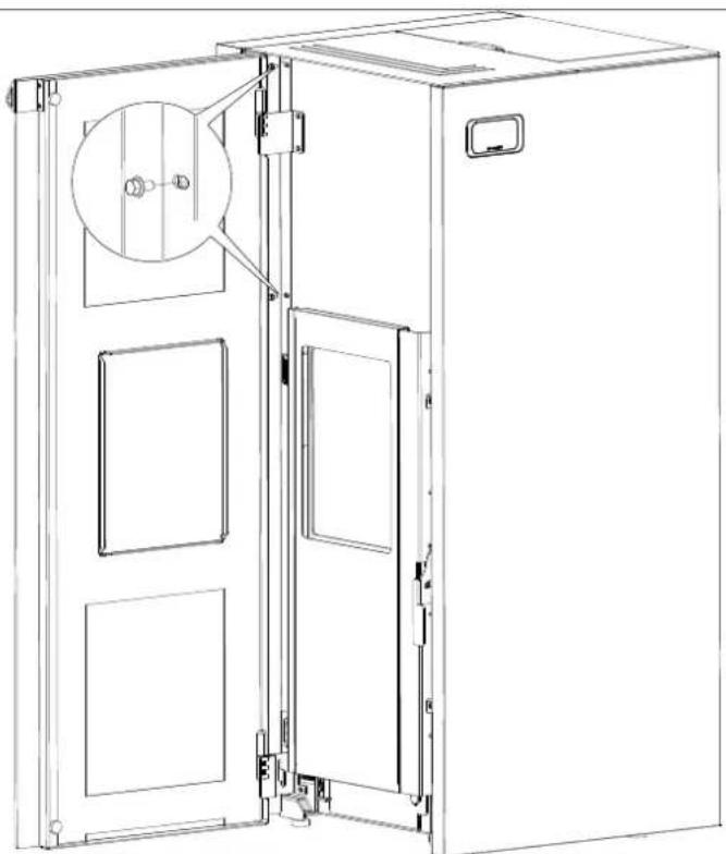
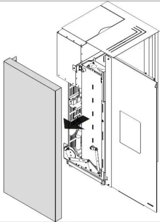
2 DISASSEMBLY AND ASSEMBLY OF PANELS
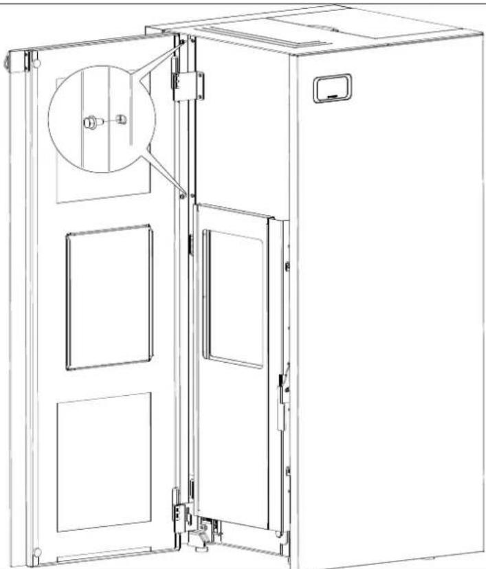
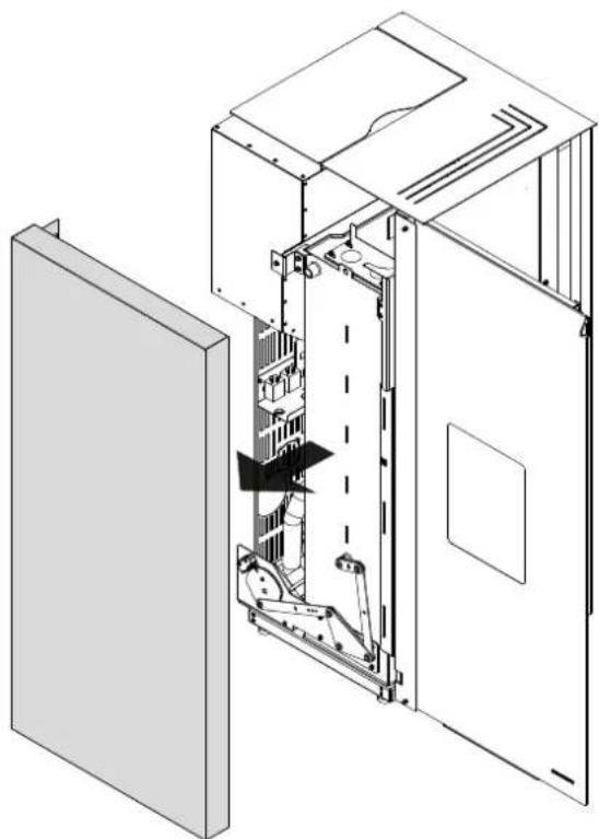
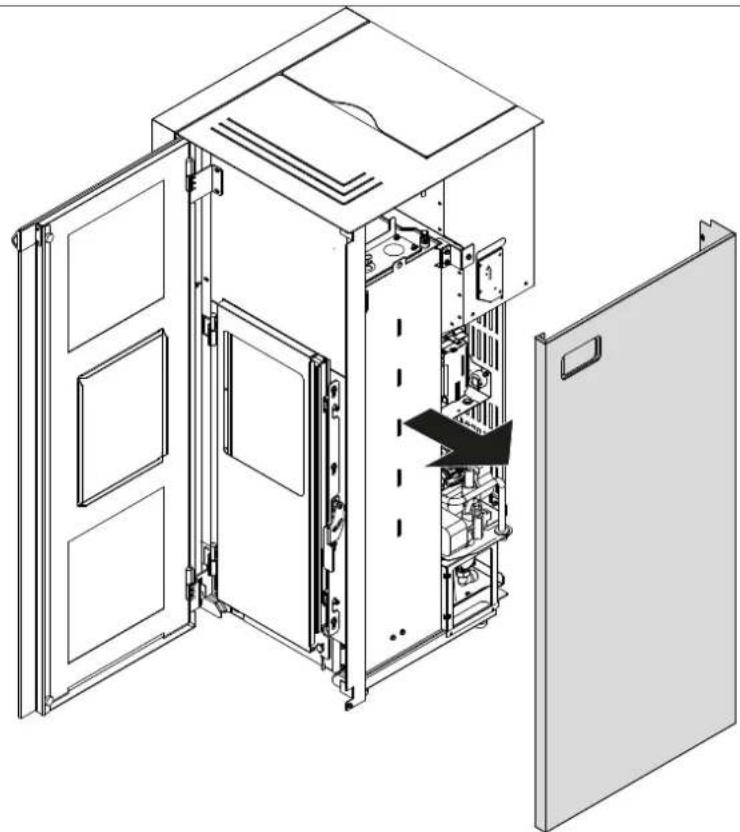
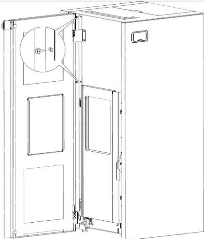
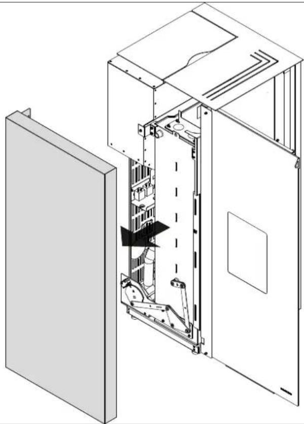
2.1 Disassembly of left side panel

natural_image
Technical line drawing of a computer tower internal structure showing ventilation slots and drive ports (no text or labels)Fig. 3
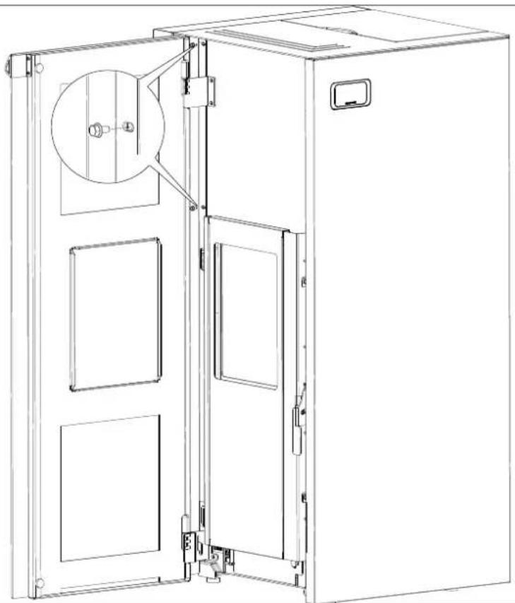
natural_image
Technical line drawing of a cabinet with open doors and internal compartments, showing internal components and a magnified inset (no text or symbols)Fig. 4
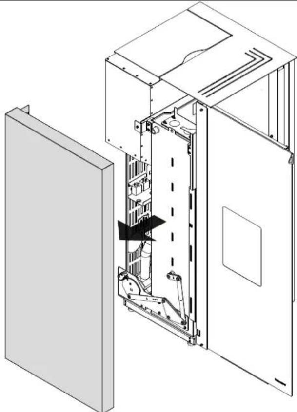
natural_image
Technical line drawing of an open industrial refrigerator with internal components and a door panel (no text or symbols)Fig. 5
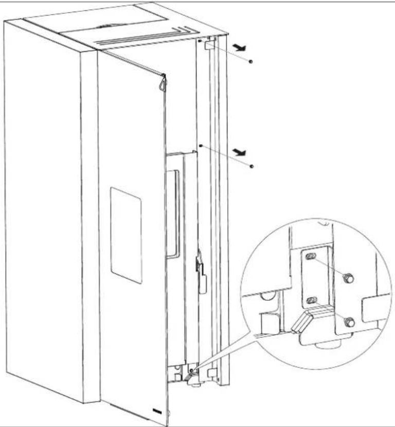
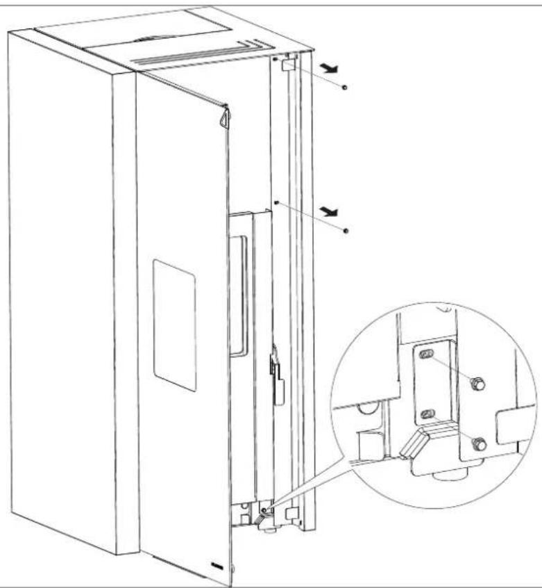
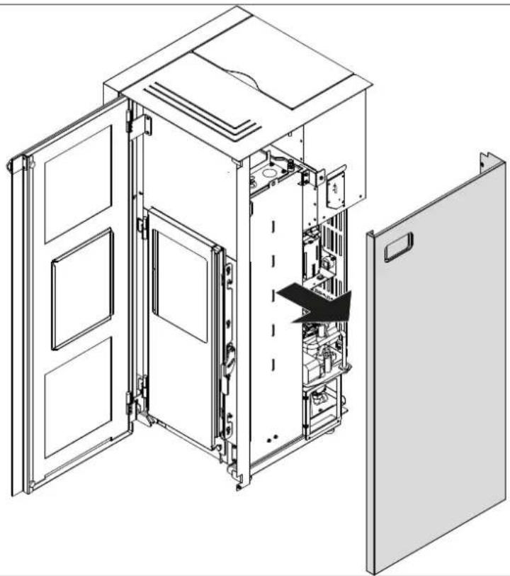
2.2 Disassembly of right side panel
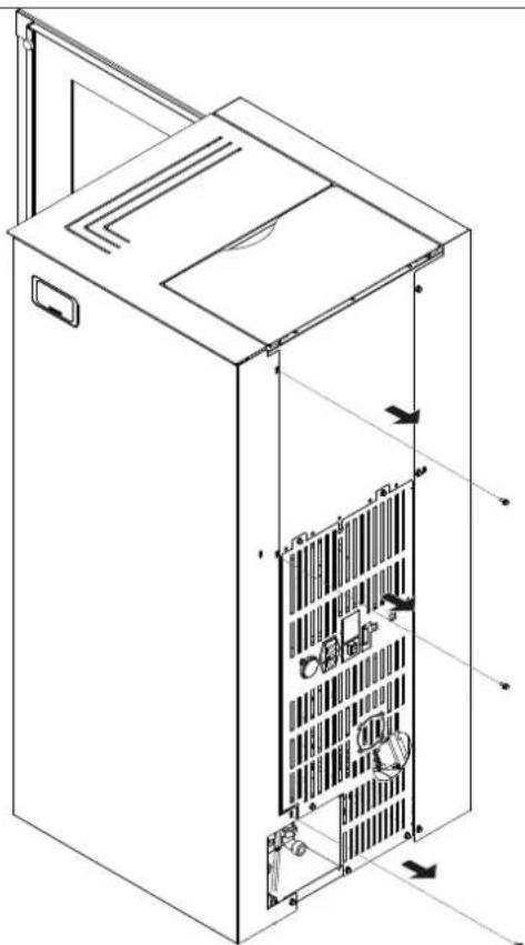
natural_image
Technical line drawing of a server rack unit with ventilation grilles and internal components (no text or labels)Fig. 6
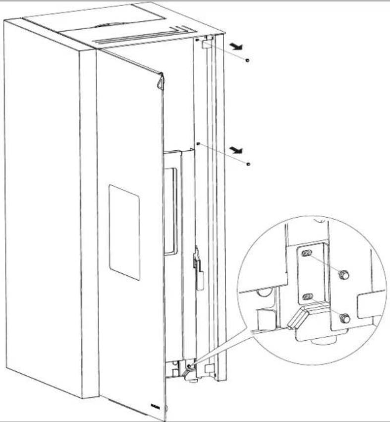
natural_image
Technical line drawing of a door frame with an inset close-up showing internal components (no text or symbols)Fig. 7
natural_image
Technical line drawing of an open industrial refrigerator with internal compartments and a door (no text or symbols)Fig. 8
2.3 Disassembly of back panel
natural_image
Technical line drawing of an internal server unit with internal components and ventilation slots (no text or labels)Fig. 9
To assemble the components, follow the operations shown in the disassembly figures in reverse order.
INHALTSVERZEICHNIS
natural_image
Technical line drawing of an electrical enclosure with internal components and wiring (no text or symbols)
natural_image
Architectural floor plan showing room layouts and staircases (no text or labels)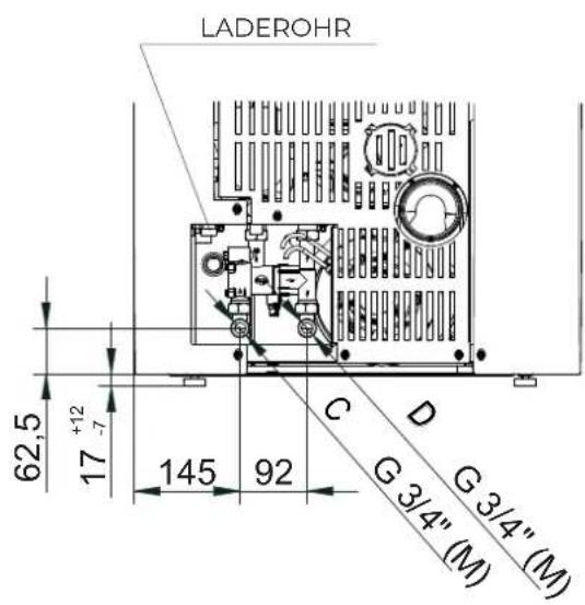
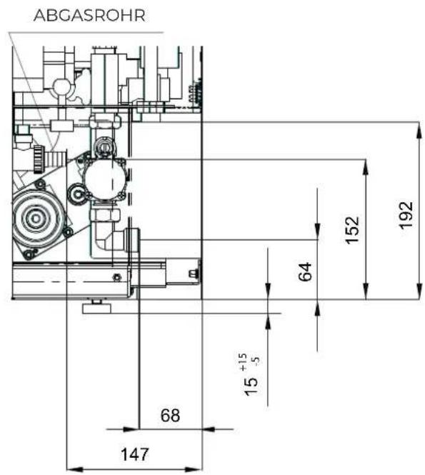
Abb. 2
natural_image
Technical line drawing of a computer tower internal structure showing ventilation slots and drive ports (no text or labels)Abb. 3
natural_image
Technical line drawing of a double door with internal compartments and a circular inset showing a bolt (no text or symbols)Abb. 4
natural_image
Technical line drawing of an internal device housing with internal components and a door panel (no text or symbols)Abb. 5
natural_image
Technical line drawing of a server rack unit with internal components and ventilation ducts (no text or labels)Abb. 6
natural_image
Technical line drawing of a cabinet or enclosure with internal components and an inset close-up showing a bracket detail (no text or symbols present)Abb. 7
natural_image
Technical line drawing of an open industrial refrigerator with internal compartments and a door handle (no text or symbols)Abb. 8
natural_image
Technical line drawing of an internal server unit with visible internal components and ventilation slots (no text or labels)Abb. 9
natural_image
Technical line drawing of an electrical enclosure with internal components and wiring (no text or symbols)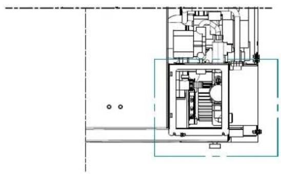
natural_image
Architectural floor plan showing room layouts and staircases (no text or labels)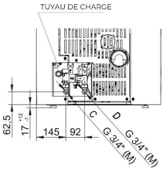
Fig. 2
D
natural_image
Technical line drawing of a computer tower internal structure showing ventilation slots and drive ports (no text or labels)Fig. 3
natural_image
Line drawing of a double door with an inset showing a circular component (no text or symbols)Fig. 4
natural_image
Technical line drawing of an internal device housing with visible internal components and mounting brackets (no text or symbols)Fig. 5
natural_image
Technical line drawing of a server rack unit with internal panel and ventilation slots (no text or labels)Fig. 6
natural_image
Technical line drawing of a refrigerator with an inset close-up showing internal components (no text or symbols)Fig. 7
natural_image
Technical line drawing of an open industrial refrigerator with internal components and a door open (no text or symbols)Fig. 8
natural_image
Technical line drawing of an internal server unit with internal components and ventilation duct (no text or symbols)Fig. 9
natural_image
Technical line drawing of an electrical enclosure with internal components and wiring (no text or symbols)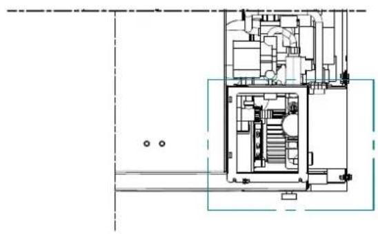
natural_image
Architectural floor plan showing room layouts and staircases (no text or labels)
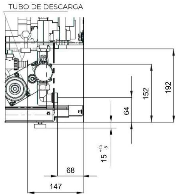
Fig. 2
natural_image
Technical line drawing of a computer tower internal structure showing ventilation grilles and drive bays (no text or labels)Fig. 3
natural_image
Line drawing of a double door with internal doors and a circular inset showing a component (no text or symbols)Fig. 4
natural_image
Technical line drawing of an open industrial machine casing with internal components and a door panel (no text or symbols)Fig. 5
natural_image
Technical line drawing of a server rack unit with internal panel and ventilation slots (no text or labels)Fig. 6
natural_image
Technical line drawing of a cabinet or enclosure with internal components and a magnified inset showing a close-up detail (no text or symbols present)Fig. 7
natural_image
Technical line drawing of an open refrigerator internal compartments, showing internal structure and door opening (no text or labels)Fig. 8
natural_image
Technical line drawing of an internal server unit with visible internal components and ventilation slots (no text or labels)Fig. 9
Palazzetti reserves the right to change its products at any time and without notice in order to improve them without compromising their essential characteristics.
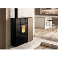
Brand : Palazzetti
Model : Ecofire Dadò Idro 10
Category : Frying Pan