
AEX16 - Switch Lorex - Free user manual and instructions
Find the device manual for free AEX16 Lorex in PDF.

| Product Type | 16-Port PoE Switch |
| Number of Ethernet Ports | 16 ports RJ45 10/100 Mbps (PoE), 1 port RJ45 10/100/1000 Mbps, 1 combo SFP port 10/100/1000 Mbps |
| PoE Standard | IEEE 802.3af/at |
| Total PoE Budget | 250 W |
| Maximum Power per PoE Port | 30 W |
| Long Range Ports | 8 ports (9-16) up to 600 m with Ethernet cable |
| Network Function | Auto MDI/MDIX, auto-negotiation 10/100/1000 Mbps |
| Power Supply | 100-240 V AC, 50/60 Hz |
| Grounding | Grounding column for surge protection |
| Installation | Desktop (rubber feet) or 19-inch rack mount (brackets included) |
| LED Indicators | PWR, LNK/ACT, PoE-in-Use, PoE Max |
| Safety | Do not disassemble, avoid water and damp areas, allow ventilation space, use specified voltage |
| Maintenance | Clean with dry cloth, disconnect before cleaning, do not use liquids or chemical cleaners |
| Package Contents | 4 rubber feet, 2 rack mount brackets, 8 screws, SFP dust cap |
| Compatibility | IP cameras, access points, PoE IP phones (IEEE 802.3af/at) |
| Automatic Detection | Automatic detection and powering of compatible powered devices (PD) |
| ePoE Long Range Function | Compatible with Lorex ePoE cameras (e.g., Nocturnal Series N4) |
Frequently Asked Questions - AEX16 Lorex
User questions about AEX16 Lorex
0 question about this device. Answer the ones you know or ask your own.
Ask a new question about this device
Download the instructions for your Switch in PDF format for free! Find your manual AEX16 - Lorex and take your electronic device back in hand. On this page are published all the documents necessary for the use of your device. AEX16 by Lorex.
USER MANUAL AEX16 Lorex
natural_image
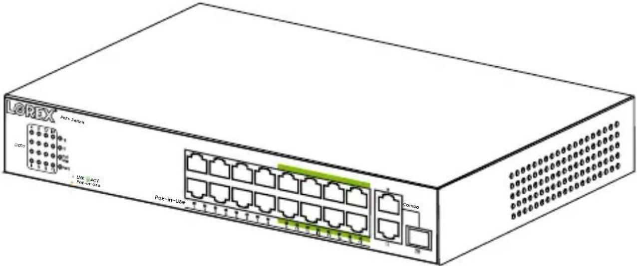
Illustration of a network switch device with multiple ports and ventilation slots (no text or labels)PoE Switch Commutateur PoE Commutador PoE
natural_image
Line drawing of a coiled cable with a power plug (no text or symbols)Power Cord Câble d'alimentation Cable de alimentación
- Follow all instructions for safe use and best performance.
- Use the switch within given temperature, humidity and voltage levels noted in the switch specifications.
- Do not disassemble the switch.
- You may need to clean periodically using a cloth. If you need to clean the switch, disconnect it from its power source first. Do not clean the switch with any liquid, harsh, chemical-based cleaners, or damp materials.
- Keep the switch away from water and out of damp areas.
- Not intended for submersion in water. Installation in a sheltered location recommended.
- Do not place the switch on unstable surfaces or underneath heavy objects, and avoid dropping the switch.
- Allow for adequate space for ventilation between the device and objects around it.
- Ensure that the operating voltage is the same as labeled in the switch.
This 16-port PoE switch contains 8 ports supporting long-range PoE transmission up to 600 m when using a single Ethernet cable connecting with a network IP camera (sold separately). Each port supports MDI/MDIX auto-flip and wire speed forwarding function. Its PoE ports automatically detect and supply power up to 30 W with IEEE 802.3af/at compliant Powered Devices (PDs). The total PoE budget of this switch can support up to 250 W. The electrical power is transmitted along with data in one single cable allowing you to expand your network where there are no powerlines or outlets, and use AP and IP cameras or IP phones.
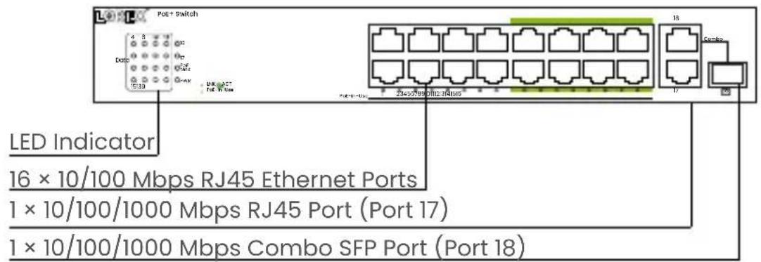
The front panel consists of Ethernet ports and LED indicators.
| PWR Off | The switch has no power supply. | |
| [5x23] | The switch has power. | |
| LNK/ACT Off | The network is not connected. | |
 | A device is successfully connected. | |
 | The switch is actively sending or receiving data over that port. | |
| PoE-in-Use | Off No | PoE powered device (PD) connected. |
 | PoE PD connected to the port is supplying power. | |
| PoE Max Off | PoE power is less than 80% of total power. | |
 | PoE power is more than 80% of total power. | |
10/100/1000 Mbps RJ45 Ports
These RJ45 ports support 10 Mbps, 100 Mbps, 1000 Mbps rate adaptive functions, and (Auto-MDI/MDIX) functions depending on the port. Ports 1-16 support a 10/100 Mbps transmission rate, and the 18 ports support a 10/100/1000 Mbps transmission rate. Each port has a corresponding indicator.
Combo Port
The combo port is located on the right side of the panel, and is an optical multiplex port, which refers to two Ethernet interfaces (usually one optical and one electrical) on the device panel. Users can choose one of them to use according to the actual networking situation, but they cannot work at the same time. Two ports share one indicator. There is only one forwarding interface inside the device. Combo port 18 is a SFP port. RJ45 or SFP connections can be used here, but not simultaneously.
Note: Ports 9-16, are long range PoE ports that can connect to a Lorex ePoE camera (e.g., Nocturnal Series - N4) using a single Ethernet cable up to 2000 feet / 600 meters without a PoE repeater needed in-between. This can save costs and simplify whole network deployment architectures.
Back Panel
The switch's back panel features an AC power port that accepts a voltage input range of 100-240V (50/60Hz) AC, along with surge protection grounding column and a fan port.
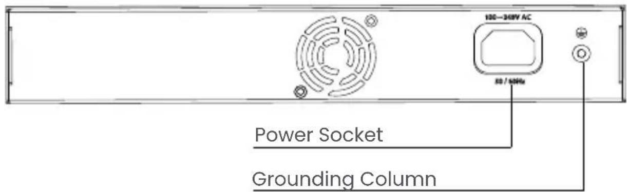
Connect the female power connector to the power socket, and the male connector to the AC power outlet.
The switch includes a lightning protection mechanism. The switch can also be grounded using the PE (Protecting Earth) cable of an AC cord, or with a ground cable.
FR - Aperçu
Panneau avant
Ports RJ45 10/100/1000 Mo/s
Install in an area that can support the total weight of the camera and accessories.
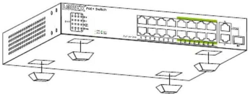
Desktop installation:
Attach the provided rubber feet at each bottom corner of the switch.
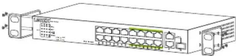
Rack mount installation:
Your switch can be installed on an EIA-19" (48.26 cm) equipment rack.
-
Install the mounting brackets on each of the switch's side panels using the provided screws.
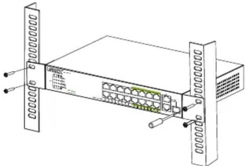
-
Use the provided screws to mount the switch to the rack.
natural_image
Diagram of a network switch device with ports and connectors (no text labels or symbols)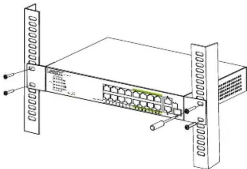
natural_image
Technical line drawing of a server rack with ports and connectors (no text or symbols)FR - Installation

natural_image
Technical line drawing of a server rack with ports and connectors (no text or symbols)ES - Instalación

natural_image
Line drawing of a network switch device with ports and connectors (no text or symbols)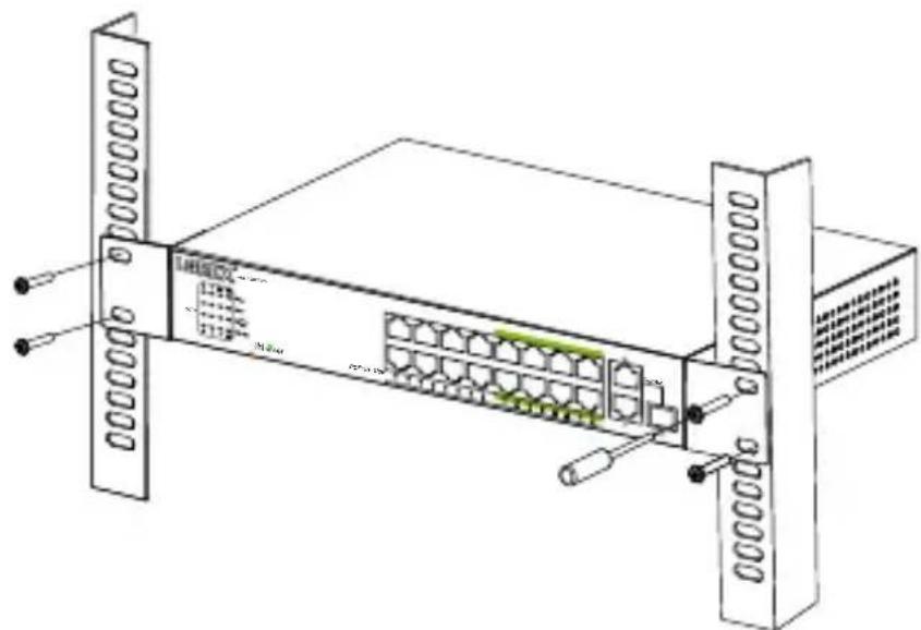
natural_image
Technical line drawing of a server rack with ports and connectors (no text or symbols)EN - Powering On The Switch
Please connect the AC power cord to the back of the switch and to an electrical outlet (preferably grounded). When powered on, the LED indicators flash for one second, representing system start-up. The power LED indicator will then turn green.
For the product compatibility chart, please visit:
lorex.com/compatibility
LOREX
Copyright © 2024 Lorex Technology Inc.
As our products are subject to continuous improvement, Lorex reserves the right to modify product design, specifications and prices, without notice and without incurring any obligation. E&OE. All rights reserved.
pro.lorex.com
help.lorex.com/AEX16-series
AEX16_QSG_EN-FR-ES_R2