
WH-WXG16ME8 - Air Conditioning PANASONIC - Free user manual and instructions
Find the device manual for free WH-WXG16ME8 PANASONIC in PDF.

| Product type | Reversible air conditioning / Air-to-water heat pump |
| Brand | Panasonic |
| Model | WH-WXG16ME8 |
| Heating capacity (nominal) | 16 kW |
| Cooling capacity (nominal) | 14 kW |
| Domestic hot water (DHW) capacity | 5.6 kW (DHW) |
| Outdoor unit dimensions (W × H × D) | 1050 × 1350 × 370 mm |
| Outdoor unit weight | 98 kg |
| Power supply | Single phase 230 V / 50 Hz |
| Refrigerant | R32 |
| Noise level (outdoor unit) | ~55 dB(A) |
| Operating temperature range | -15 °C to 35 °C (heating), -10 °C to 46 °C (cooling) |
| Maintenance and cleaning | Clean air filters every month; have the refrigerant circuit checked every 2 years |
| Safety | Overvoltage protection, refrigerant leakage detection, automatic shutdown in case of overheating |
| Spare parts and repairability | Available from Panasonic authorized dealers; repairability index: 7.4/10 |
| Warranty | 2 years (parts and labor) |
| General information | High-performance heat pump with integrated domestic hot water production. Compatible with solar thermal panels and app control |
Frequently Asked Questions - WH-WXG16ME8 PANASONIC
User questions about WH-WXG16ME8 PANASONIC
0 question about this device. Answer the ones you know or ask your own.
Ask a new question about this device
Download the instructions for your Air Conditioning in PDF format for free! Find your manual WH-WXG16ME8 - PANASONIC and take your electronic device back in hand. On this page are published all the documents necessary for the use of your device. WH-WXG16ME8 by PANASONIC.
USER MANUAL WH-WXG16ME8 PANASONIC
Operating Instructions
Air-to-Water Heatpump Outdoor Unit /
Air-to-Water Heatpump Outdoor Unit and Indoor Unit
natural_image
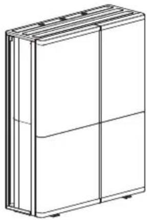
Line drawing of a rectangular box with vertical panels and horizontal connectors (no text or symbols)Model No.
Outdoor Unit
WH-WXG09ME8
WH-WXG12ME8
WH-WXG16ME8

natural_image
Line drawing of a rectangular industrial or electrical cabinet with multiple terminals and a window (no text or symbols)Applicable Indoor Unit
Hydromodule + Tank
WH-ADC0316M9E82
WH-ADC0316M9E8AN2
ENGLISH
Before operating the system, please read these operating instructions thoroughly and keep them for future reference.
Thank you for purchasing Panasonic product.
Installation Instructions attached.
Serial number and production year please refer to name plate.
Table of contents
System overview 3
Operating conditions 3
Safety precautions 4-16
Protective zone 17
Remote Controller buttons and display 18-19
Initialization 20
Quick Menu 21
How to use the Quick Menu 22-26
Menus 27-51
For user
1 Function setup 27-28
1.1 Weekly timer
1.2 Holiday timer
1.3 Quiet timer
1.4 Quiet priority
1.5 Room heater
1.6 Tank heater
1.7 Sterilization
1.8 DHW mode
2 System check 29
2.1 Energy monitor
2.2 System information
2.3 Error history
2.4 Compressor
2.5 Heater
3 Personal setup 30-31
3.1 Remote control No.
3.2 Touch sound
3.3 LCD contrast
3.4 Backlight
3.5 Backlight intensity
3.6 Clock format
3.7 Date & Time
3.8 Language
3.9 Unlock password
4 Service contact ....31
4.1 Contact 1 / Contact 2
For installer
5 Installer setup > System setup ....32-44
5.1 Optional PCB connectivity
5.2 Zone & Sensor
5.3 Heater capacity
5.4 Anti freezing
5.5 Tank connection
5.6 DHW capacity
5.7 Buffer tank connection
5.8 Tank heater
5.9 Base pan heater
5.10 Alternative outdoor sensor
5.11 Bivalent connection
5.12 External SW
5.13 Solar connection
5.14 External error signal
5.15 Demand control
5.16 SG ready
5.17 External compressor SW
5.18 Circulation liquid
5.19 Heat-Cool SW
5.20 Force heater
5.21 Force defrost
5.22 Defrost signal
5.23 Pump flowrate
5.24 DHW Defrost
5.25 Heating control
5.26 External meter
5.27 Electrical anode
5.28 Extra pump
5.29 External heater
5.30 Static pressure
5.31 Cooling capacity
6 Installer setup > Operation setup .....45-49
6.1 Heat
6.2 Cool
6.3 Auto
6.4 Tank
7 Installer setup > Service setup 49-50
7.1 Pump maximum speed
7.2 Zone2 pump speed
7.3 Dry concrete
7.4 Service contact
8 Installer setup > Remote control setup ....51
Cleaning instructions ....52-53
Troubleshooting 54-55
Information 56-57

Before use, make sure the system has been installed correctly by an authorised dealer/specialist according to the given instructions.
- Panasonic Air-to-Water is a system that consists of a single outdoor unit or two units: an indoor unit and an outdoor unit. The indoor unit consists of the Hydromodule and a sanitary water tank.
• These operating instructions describe how to operate the system using a single outdoor unit or the indoor and outdoor units. - As for the operation of other products such as radiator, external thermo controller, and underfloor units, refer to the operating instructions of each product.
- System could be locked to operate in HEAT mode and disable COOL mode.
- Some functions described in this manual may not be applicable to your system.
- Ensure that incoming water is clean. When water tapped from a private well or spring water, it may be necessary to supplement with an extra water filter.
- Do avoid using water containing salt, acid, and other impurities which may corrode the tank and its component.
- Consult your nearest authorised dealer/specialist for further information.
• Install the outdoor unit outdoors.
System overview
(Structure of units varies by models.)
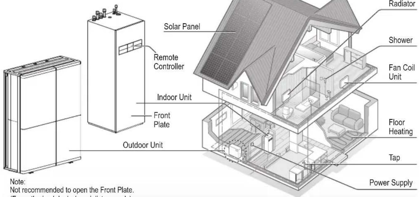
Note:
Not recommended to open the Front Plate.
(For authorised dealer/specialist use only)
The illustrations in this manual are for explanation purposes only and differ from the actual unit.
They are subject to change without notice for future improvement.
In the future explanations, there will be parts that will explain the outdoor unit alone or in combination with the indoor unit, but the content will differ depending on the user's system.
Children aged from 3 to 8 years are only allowed to operate the tap connected to the water heater.
Operating conditions
| HEATING (TANK) HEATING (CIRCUIT) * | 1, *2 COOLING (CIRCUIT) | ||
| Water outlet temperature (°C)(Min. / Max.) | - / 65*3 | 25 / 55 (Below Ambient -25 °C) *125 / 75 (Above Ambient -15 °C) *4 | 5 / 20 |
| Outdoor ambient temperature (°C)(Min. / Max.) | -28 / 43 -28 / 35 | 10 / 43 | |
When the outdoor temperature is out of the range in the table, the heating capacity will drop significantly and the unit may stop operating for its protection.
The unit will restart automatically after the outdoor temperature returns to the specified range.
*1 The system is locked to operate without COOL mode. It can be unlocked only by authorised installers or our authorised service partners.
*2 Only displayed when COOL mode is unlocked (This means when COOL mode is available)
*3 When outdoor ambient is under -15 °C, only the backup heater operate above 55 °C. (Outdoor unit don't have backup heater.)
*4 Between outdoor ambient -15 °C and -25 °C, the water outlet temperature gradually decreases from 75 °C to 55 °C.
To prevent personal injury, injury to others or property damage, please comply with the following: Incorrect operation due to failure to follow instructions below may cause harm or damage, the seriousness of which is classified as below:

WARNING
This sign warns of death or serious injury.

CAUTION
This sign warns of injury or damage to property.
The instructions to be followed are classified by the following symbols:

This symbol denotes an action that is PROHIBITED.


These symbols denote actions COMPULSORY.

WARNING
Indoor unit and outdoor unit

This appliance can be used by children aged from 8 years and above and persons with reduced physical, sensory or mental capabilities or lack of experience and knowledge if they have been given supervision or instruction concerning use of the appliance in a safe way and understand the hazards involved. Children shall not play with the appliance. Cleaning and user maintenance shall not be made by children without supervision.
Please consult an authorised dealer or specialist to clean the internal parts, repair, install, remove, disassemble and reinstall the unit. Improper handling may cause leakage, electric shock or fire.
Confi rm with authorised dealer or specialist on usage of any specified refrigerant type. Using refrigerant type other than the specified may cause product damage, burst and injury etc.

Do not use means to accelerate the defrosting process or to clean, other than those recommended by manufacturer.
Any unfit method or using incompatible material may cause product damage, burst and serious injury.
Do not install the unit in a potentially explosive or fl ammable atmosphere. Otherwise, fi re may be caused.

Do not insert your fingers or other objects into the Air to water indoor or outdoor unit, rotating parts may cause injury.

Do not touch the outdoor unit during lightning, it may cause electric shock.
Do not sit or step on the unit, you may fall down accidentally.

Do not install the indoor unit outdoors. Indoor unit is designed for indoor installation only.
Power supply

Do not use a modified cable, joint cable, extension cable or unspecified cable to prevent overheating and fire.


To prevent overheating, fire or electric shock:
- Do not share the same power outlet with other equipment.
- Do not operate with wet hands.
- Do not over bend the power supply cable.

If the supply cable is damaged, it must be replaced by the manufacturer, service agent or similarly qualified persons in order to avoid a hazard.
This unit is equipped with Residual Current Circuit Breaker/Earth Leakage Circuit Breaker (RCCB/ELCB). Ask an authorised dealer/specialist to check RCCB/ELCB operation regularly, especially after installation, inspection, and maintenance. RCCB/ELCB malfunction may result in electric shock and/or fi re.

It is strongly recommended that Install Residual Current Device (RCD) on-site to prevent electric shock and/or fire.
Before obtaining access to terminals, all supply circuits must be disconnected.
Stop using the product if any abnormality/failure occurs and disconnect the power supply. (Risk of smoke/fi re/electric shock) Examples of abnormality/failure
• RCCB/ELCB trips frequently.
- Burning smell is observed.
- Abnormal noise or vibration of the unit is observed.
- Hot water leaks from the indoor unit or outdoor unit.
Contact your local dealer/specialist immediately for maintenance/repair.
Wear gloves during inspection and maintenance.

This equipment must be earthed to prevent electrical shock or fire.

Prevent electric shock by switching off the power supply: - Before cleaning or servicing, - When extended non-use.
To avoid electric shock, burn and/or fatal injury, make sure to disconnect all power supplies before accessing any terminal in the indoor unit and outdoor unit.

CAUTION
Indoor unit and outdoor unit

Do not wash the indoor unit with water, benzine, thinner or scouring powder to avoid damage or corrosion at the unit.
Do not install the unit close to any combustibles or at bathroom. Otherwise, it may cause electric shock and/or fi re.
Do not touch the sharp aluminium fi n, sharp parts may cause injury.

Do not use the system during sterilisation in order to prevent scalding with hot water, or overheating of shower.
Do not dismantle the unit for cleaning purpose to avoid injury.
Do not step onto an unstable bench when cleaning the unit to avoid injury.
Do not place a vase or water container on the unit. Water may enter the unit and degrade the insulation. This may cause an electric shock.

Prevent water leakage by ensuring drainage pipe is:
-Connected properly,
-Kept clear of gutters and containers, or
-Not immersed in water
After a long period of use or use with any combustible equipment, aerate the room regularly.
After a long period of use, make sure the installation rack does not deteriorate to prevent the unit from falling down.

Water piping in the occupied space shall be installed in such a way to protect against accidental damage in operation and service.
Precautions shall be taken to avoid excessive vibration or pulsation to Water piping.
Protect the Water piping from accidental rupture due to moving furniture or reconstruction activities.
Remote Controller

Do not wet the Remote Controller. Failure to do so may result in electric shock and/or fi re.
Do not press the buttons on the Remote Controller using hard and sharp objects. Failure to do so may cause damage to the unit.
Do not wash the Remote Controller using water, benzine, thinner or scouring powder.
Do not inspect or maintain the Remote Controller by yourself. Consult an authorised dealer/specialist in order to prevent personal injury caused by incorrect operation.

WARNING
This appliance is fi lled with R290 (Extremely fl ammable gas, safety A3 group per ISO 817). If the refrigerant is leaked and exposed to an external ignition source, there is a risk of fi re.
Indoor unit and outdoor unit

Protective zone is defined near the product. See section Protective zone.
Be aware that refrigerant may not contain an odour, highly recommended to ensure suitable fl ammable refrigerant gas detectors are present, operating and able to warn of a leak.
Keep any required ventilation openings clear of obstruction.

Do not pierce or burn as the appliance is pressurized. Do not expose the appliance to heat, flame, sparks, or other sources of ignition. Else it may explode and cause injury or death.
Precaution for using R290 refrigerant

The mixing of different refrigerants within a system is prohibited.
- Operation, maintenance, repairing and refrigerant recovery should be carried out by trained and certified personnel in the use of flammable refrigerants and as recommended by the manufacturer. Any personnel conducting an operation, servicing or maintenance on a system or associated parts of the equipment should be trained and certified.
- Any part of refrigerating circuit (evaporators, air coolers, AHU, condensers or liquid receivers) or piping should not be located in the proximity of heat sources, open flames, operating gas appliance or an operating electric heater.
- The user/owner or their authorised representative shall regularly check the alarms, mechanical ventilation and detectors, at least once a year, where as required by national regulations, to ensure their correct functioning.
- A logbook shall be maintained. The results of these checks shall be recorded in the logbook.
- In case of ventilations in occupied spaces shall be checked to confirm no obstruction.

- Before a new refrigerating system is put into service, the person responsible for placing the system in operation should ensure that trained and certified operating personnel are instructed on the basis of the instruction manual about the construction, supervision, operation and maintenance of the refrigerating system, as well as the safety measures to be observed, and the properties and handling of the refrigerant used.
- The general requirement of trained and certified personnel are indicated as below:
a) Knowledge of legislation, regulations and standards relating to fl ammable refrigerants; and,
b) Detailed knowledge of and skills in handling fl ammable refrigerants, personal protective equipment, refrigerant leakage prevention, handling of cylinders, charging, leak detection, recovery and disposal; and,
c) Able to understand and to apply in practice the requirements in the national legislation, regulations and Standards; and,
d) Continuously undergo regular and further training to maintain this expertise.
e) Ensure protection devices, refrigerating cycle are well protected against adverse environmental effects (such as the danger of water collecting and freezing in relief pipes or the accumulation of dirt and debris).

1. Installation (Space)
- Must ensure that water pipe-work shall be protected from physical damage.
- Must ensure mechanical connections be accessible for maintenance purposes.
- In cases that require mechanical ventilation, ventilation openings shall be kept clear of obstruction.
- Must comply with national gas regulations, state municipal rules and legislation. Notify relevant authorities in accordance with all applicable regulations.
- When disposal of the product, do follow to the precautions in #12 and comply with national regulations. Always contact to local municipal offi ces for proper handling.

2. Servicing
2-1. Service personnel
- The system is inspected, regularly supervised and maintained by a trained and certified service personnel who is employed by the person user or party responsible.
- Ensure refrigerant charge not to leak.
- Any qualified person who is involved with working on or breaking into a refrigerant circuit should hold a current valid certifi cate from an industry-accredited assessment authority, which authorizes their competence to handle refrigerants safely in accordance with an industry recognised assessment specifi cation.
- Servicing shall only be performed as recommended by the equipment manufacturer. Maintenance and repair requiring the assistance of other skilled personnel shall be carried out under the supervision of the person competent in the use of flammable refrigerants.
- Servicing shall be performed only as recommended by the manufacturer.

2-2. Work
- Prior to beginning work on systems containing fl ammable refrigerants, safety checks are necessary to ensure that the risk of ignition is minimised. For repair to the refrigerating system, the precautions in #2-2 to #2-8 must be followed before conducting work on the system.
• Work shall be undertaken under a controlled procedure so as to minimize the risk of a flammable gas or vapour being present while the work is being performed. - All maintenance staff and others working in the local area shall be instructed and supervised on the nature of work being carried out.
- Avoid working in confined spaces. Always ensure away from source, at least 2 meter of safety distance, or zoning of free space area of at least 2 meter in radius.
- Wear appropriate protective equipment, including respiratory protection, as conditions warrant.
- Keep all sources of ignition and hot metal surfaces away.

2-3. Checking for presence of refrigerant
- The area shall be checked with an appropriate refrigerant detector prior to and during work, to ensure the technician is aware of potentially fl ammable atmospheres.
- Ensure that the leak detection equipment being used is suitable for use with fl ammable refrigerants, i.e. non sparking, adequately sealed or intrinsically safe.
- In case of leakage/spillage happened, immediately ventilate area and stay upwind and away from spill/release.
- In case of leakage/spillage happened, do notify persons down wind of the leaking/spill, isolate immediate hazard area and keep unauthorized personnel out.

2-4. Presence of fi re extinguisher
- If any hot work is to be conducted on the refrigerating equipment or any associated parts, appropriate fire extinguishing equipment shall be available at hand.
- Have a dry powder or CO_2 fi re extinguisher adjacent to the charging area.

2-5. No ignition sources
- No person carrying out work in relation to a refrigerating system shall use any sources of ignition in such a manner that it may lead to the risk of fire or explosion. They must not be smoking when carrying out such work.
- All possible ignition sources, including cigarette smoking, should be kept sufficiently far away from the site of installation, repairing, removing and disposal, during which fl ammable refrigerant can possibly be released to the surrounding space.
- Prior to work taking place, the area around the equipment is to be surveyed to make sure that there are no fl ammable hazards or ignition risks.
- "No Smoking" signs shall be displayed.

2-6. Ventilated area
- Ensure that the area is in the open or that it is adequately ventilated before breaking into the system or conducting any hot work.
- A degree of ventilation shall continue during the period that the work is carried out.
- The ventilation should safely disperse any released refrigerant and preferably expel it externally into the atmosphere.

2-7. Checks to the refrigerating equipment
- Where electrical components are being changed, they shall be fit for the purpose and to the correct specification.
- At all times the manufacturer's maintenance and service guidelines shall be followed.
- If in doubt consult the manufacturer's technical department for assistance.
- The following checks shall be applied to installations using fl ammable refrigerants.
-The ventilation machinery and outlets are operating adequately and are not obstructed.
-If an indirect refrigerating circuit is being used, the secondary circuit shall be checked for the presence of refrigerant.
-Marking to the equipment continues to be visible and legible. Markings and signs that are illegible shall be corrected.
-Refrigerating pipe or components are installed in a position where they are unlikely to be exposed to any substance which may corrode refrigerant containing components, unless the components are constructed of materials which are inherently resistant to being corroded or are properly protected against being so corroded.

2-8. Checks to electrical devices
- Repair and maintenance to electrical components shall include initial safety checks and component inspection procedures.
- Initial safety checks shall include but not limit to:-
-That capacitors are discharged: this shall be done in a safe manner to avoid possibility of sparking.
-That there are no live electrical components and wiring are exposed while charging, recovering or purging the system.
-That there is continuity of earth bonding.
- At all times the manufacturer's maintenance and service guidelines shall be followed.
- If in doubt consult the manufacturer's technical department for assistance.
- If a fault exists that could compromise safety, then no electrical supply shall be connected to the circuit until it is satisfactorily dealt with.
- If the fault cannot be corrected immediately but it is necessary to continue operation, an adequate temporary solution shall be used.
- The owner of the equipment must be informed or reported so all parties are advised thereinafter.

3. Repairs to sealed components
- During repairs to sealed components, all electrical supplies shall be disconnected from the equipment being worked upon prior to any removal of sealed covers, etc.
- If it is absolutely necessary to have an electrical supply to equipment during servicing, then a permanently operating form of leak detection shall be located at the most critical point to warn of a potentially hazardous situation.
- Particular attention shall be paid to the following to ensure that by working on electrical components, the casing is not altered in such a way that the level of protection is affected. This shall include damage to cables, excessive number of connections, terminals not made to original specification, damage to seals, incorrect fi tting of glands, etc.
- Ensure that apparatus is mounted securely.
- Ensure that seals or sealing materials have not degraded such that they no longer serve the purpose of preventing the ingress of flammable atmospheres.
- Replacement parts shall be in accordance with the manufacturer's specifications.
NOTE: The use of silicon sealant may inhibit the effectiveness of some types of leak detection equipment.
Intrinsically safe components do not have to be isolated prior to working on them.

4. Repairs to intrinsically safe components
- Do not apply any permanent inductive or capacitance loads to the circuit without ensuring that this will not exceed the permissible voltage and current permitted for the equipment in use.
- Intrinsically safe components are the only types that can be worked on while live in the presence of a flammable atmosphere.
- The test apparatus shall be at the correct rating.
- Replace components only with parts specified by the manufacturer. Unspecified parts by manufacturer may result ignition of refrigerant in the atmosphere from a leak.

5. Cabling
- Check that cabling will not be subject to wear, corrosion, excessive pressure, vibration, sharp edges or any other adverse environmental effects.
- The check shall also take into account the effects of aging or continual vibration from sources such as compressors or fans.

6. Detection of fl ammable refrigerants
- Under no circumstances shall potential sources of ignition be used in the searching or detection of refrigerant leaks.
- A halide torch (or any other detector using a naked flame) shall not be used.

7. The following leak detection methods are deemed acceptable for all refrigerant systems
- No leaks shall be detected using detection equipment with sensitivity to detect leakage of 5g/year of refrigerant or better under a pressure of at least 0.25 times the maximum allowable pressure (>0.98 MPa, max 3.90 MPa), for example, a universal sniffer.
- Electronic leak detectors may be used to detect fl ammable refrigerants, but the sensitivity may not be adequate, or may need re-calibration. (Detection equipment shall be calibrated in a refrigerant-free area.)
- Ensure that the detector is not a potential source of ignition and is suitable for the refrigerant used.
- Leak detection equipment shall be set at a percentage of the LFL of the refrigerant and shall be calibrated to the refrigerant employed and the appropriate percentage of gas (25 % maximum) is confirmed.
- Leak detection fluids are also suitable for use with most refrigerants, for example, bubble method and fluorescent method agents. The use of detergents containing chlorine shall be avoided as the chlorine may react with the refrigerant and corrode the copper pipe-work.
- If a leak is suspected, all ignition sources shall be removed/extinguished.
- If a leakage of refrigerant is found which requires brazing, all of the refrigerant shall be recovered from the system. The precautions in #8 must be followed to remove the refrigerant.

8. Removal and evacuation
- When breaking into the refrigerant circuit to make repairs – or for any other purpose – conventional procedures shall be used. However, it is important that best practice is followed since flammability is a consideration. The following procedure shall be adhered to: remove refrigerant -> purge the circuit with inert gas -> evacuate -> purge with inert gas -> open the circuit by cutting. Brazing must not be used.
- The refrigerant charge shall be recovered into the correct recovery cylinders.
- The system shall be purged with OFN to render the appliance safe.
$$ \begin{array}{l} \text { OFN } = \text { oxygen free nitrogen, type of } \ \text { inert gas. } \end{array} $$
• This process may need to be repeated several times.
- Compressed air or oxygen shall not be used for this task.
- Purging shall be achieved by breaking the vacuum in the system with OFN and continuing to fi ll until the working pressure is achieved, then venting to atmosphere, and fi nally pulling down to a vacuum.
- This process shall be repeated until no refrigerant is within the system (Until the concentration of purge gas is 0.25 LFL or less by the leak detector).
$$ \text {※} 0.25 \mathrm{LFL} = 0.525 \mathrm{Vol} $$
- When the fi nal OFN charge is used, the system shall be vented down to atmospheric pressure to enable work to take place.
- This operation is absolutely vital if brazing operations on the pipe work are to take place.

- Ensure that the outlet for the vacuum pump is not close to any potential ignition sources and there is ventilation available.

9. Charging procedures
• In addition to conventional charging procedures, the following requirements shall be followed.
-Ensure that contamination of different refrigerants does not occur when using charging equipment.
-Hoses or lines shall be as short as possible to minimize the amount of refrigerant contained in them.
-Cylinders shall be kept in an appropriate position according to the instructions.
-Ensure that the refrigerating system is earthed prior to charging the system with refrigerant.
-Label the system when charging is complete (if not already).
-Extreme care shall be taken not to over fill the refrigerating system.
- Prior to recharging the system it shall be pressure tested with OFN (refer to #8).
- The system shall be leak tested on completion of charging but prior to commissioning.
- A follow up leak test shall be carried out prior to leaving the site.
- Electrostatic charge may accumulate and create a hazardous condition when charging and discharging the refrigerant. To avoid fire or explosion, dissipate static electricity during transfer by grounding and bonding containers and equipment before charging/discharging.

10. Decommissioning
- Before carrying out this procedure, it is essential that the technician is completely familiar with the equipment and all its details.
- It is recommended good practice that all refrigerants are recovered safely.
- Re-use of recovered refrigerant is prohibited.
- It is essential that electrical power is available before the task is commenced.
a) Become familiar with the equipment and its operation.
b) Isolate system electrically.
c) Before attempting the procedure ensure that:
- mechanical handling equipment is available, if required, for handling refrigerant cylinders;
- all personal protective equipment and leak detectors are available and being used correctly;
• the recovery process is supervised at all times by a competent person;
• recovery equipment and cylinders conform to the appropriate standards.
d) Make sure that cylinder is situated on the scales before recovery takes place.
e) Start the recovery machine and operate in accordance with instructions.
f) Do not over fi ll cylinders. (No more than 80 % volume liquid charge).
g) Do not exceed the maximum working pressure of the cylinder, even temporarily.

h) When the cylinders have been filled correctly and the process completed, make sure that the cylinders and the equipment are removed from site promptly and all isolation valves on the equipment are closed off.
- Electrostatic charge may accumulate and create a hazardous condition when charging or discharging the refrigerant. To avoid fire or explosion, dissipate static electricity during transfer by grounding and bonding containers and equipment before charging/discharging.

11. Labelling
• Equipment shall be labelled stating that it has been de-commissioned and emptied of refrigerant.
• The label shall be dated and signed.
- Ensure that there are labels on the equipment stating the equipment contains fl ammable refrigerant.

12. Recovery
- When removing refrigerant from a system, either for servicing or decommissioning, it is recommended good practice that all refrigerants are removed safely.
- When transferring refrigerant into cylinders, ensure that only appropriate refrigerant recovery cylinders are employed.
- Ensure that the correct number of cylinders for holding the total system charge are available.
- All cylinders to be used are designated for the recovered refrigerant and labelled for that refrigerant (i.e. special cylinders for the recovery of refrigerant).
- Cylinders shall be complete with pressure relief valve and associated shut-off valves in good working order.
- Recovery cylinders are evacuated and, if possible, cooled before recovery occurs.
- The recovery equipment shall be in good working order with a set of instructions concerning the equipment that is at hand and shall be suitable for the recovery of fl ammable refrigerants.
- Make sure the recovery equipment is not a potential ignition source and is suitable for the refrigerant you are using.
- In addition, a set of calibrated weighing scales shall be available and in good working order.
- Hoses shall be complete with leak-free disconnect couplings and in good condition.

- Before using the recovery machine, check that it is in satisfactory working order, has been properly maintained and that any associated electrical components are sealed to prevent ignition in the event of a refrigerant release. Consult manufacturer if in doubt.
- The recovered refrigerant shall be returned to the refrigerant supplier in the correct recovery cylinder, and the relevant Waste Transfer Note arranged.
- Do not mix refrigerants in recovery units and especially not in cylinders.
- If compressors or compressor oils are to be removed, ensure that they have been evacuated to an acceptable level to make certain that fl ammable refrigerant does not remain within the lubricant.
- The evacuation process shall be carried out prior to returning the compressor to the suppliers.
- Only electric heating to the compressor body shall be employed to accelerate this process.
- When oil is drained from a system, it shall be carried out safely.
This outdoor unit is filled with R290 (Extremely flammable gas, safety A3 group per ISO 817). Note that this refrigerant has a higher density than air. In case of a refrigerant leak, the leaked refrigerant may accumulate near the ground.
Prevent accumulation of refrigerant in any way that is potentially dangerous, explosive or risk suffocation. Prevent refrigerant from entering the building through building openings. Prevent accumulation of refrigerant in the drain grooves.
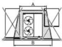
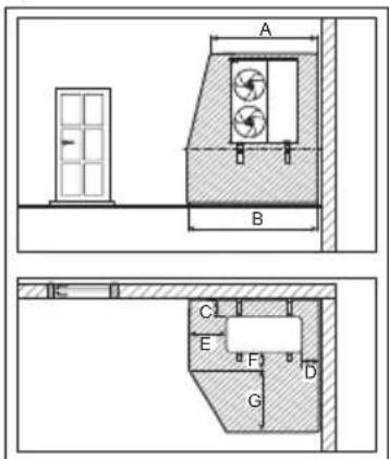
A protective zone is defined around this outdoor unit. There must be no building openings, windows, doors, light shafts, cellar entrances, escape hatches, flat-roof windows or ventilation openings in the protective zone.
There must be no ignition sources, such as heat above 360 °C, sparks, open flame, plug sockets, light switches, lamps, electrical switches or other permanent ignitions sources, in the protective zone.
The protective zone must not extend to adjacent buildings or public traffic areas (boundaries of neighbors, the public road, neighbor's private roads, subsidence area, depressions, pump shafts, sewers intakes, waste water shafts and so on.).
In the protective zone, you are not permitted to make any subsequent structural alterations which infringe the stated rules for the protective zone.
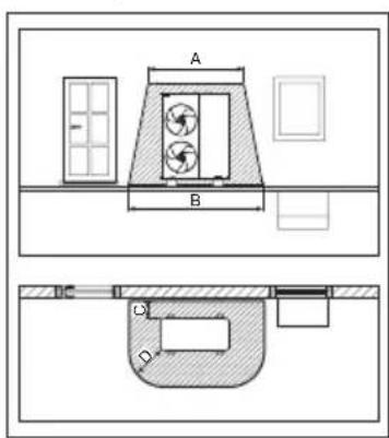
1) Protective zone for ground installation (or fl at-roof installation) at the open areas
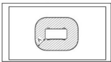
natural_image
Simple diagram showing a shaded oval shape with an internal rectangle and label 'A' (no text or symbols beyond the label)A 1000 mm
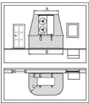
2) Protective zone for ground installation in front of a building wall
A 2200 mm
B 3200 mm
C 300 mm
D 1000 mm
3) Protective zone for ground installation in a building corner
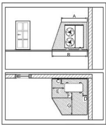
A 2200 mm
B 2700 mm
C 300 mm
D 500 mm
E 1000 mm
F 500 mm
G 1800 mm
4) Protective zone for wall installation in front of a building wall
A 2200 mm
B 3200 mm
C 300 mm
D 1000 mm
The protective zone under the product extends to the floor.
5) Protective zone for wall installation in a building corner
A 2200 mm
B 2700 mm
C 300 mm
D 500 mm
E 1000 mm
F 500 mm
G 1800 mm
The protective zone under the product extends to the floor.
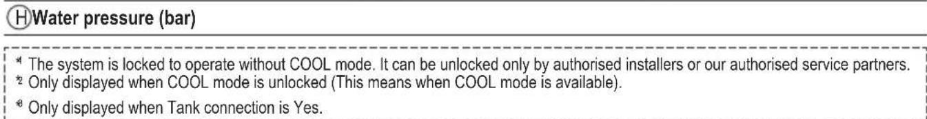
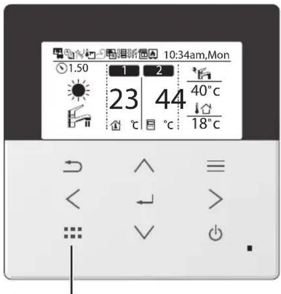
Remote Controller buttons and display
The LCD display as shown in this manual are for instructional purpose only, and may differ from the actual unit.
Buttons / Indicator
① Quick Menu button
Back button
Returns to the previous screen
LCD Display
(Actual - Dark background with white icons)
Main Menu button
For function setup
5 ON/OFF button
Starts/Stops operation
Operation indicator
⑥ Illuminates during operation, blinks during alarm.
When the backlight is off, press any button to turn it on.
(Do not press button ⑤)
The time until the backlight turns off can be changed in the Menu (Personal setup)
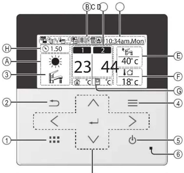
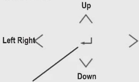
Cross key buttons
Selects an item.

Press centre

No glove

natural_image
Illustration of a hand pointing to the left (no text or symbols present)Enter button
Fixes the selected content.

No pen
natural_image
Hand holding a pen writing on paper (no text or symbols present)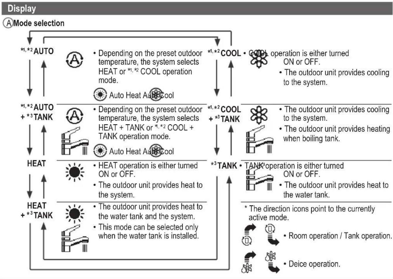
flowchart
graph TD
    A["Mode selection"] --> B["*1,*2 AUTO"]
    B --> C["HEAT + *3 TANK"]
    C --> D["*1,*2 AUTO + *3 TANK"]
    D --> E["HEAT"]
    E --> F["*1,*2 AUTO"]
    F --> G["COOL + *3 TANK"]
    G --> H["*1,*2 COOL + *3 TANK"]
    H --> I["TANK operation is either turned ON or OFF."]
    I --> J["The outdoor unit provides cooling to the system."]
    H --> K["TANK operation is either turned ON or OFF."]
    K --> L["The outdoor unit provides heating when boiling tank."]
    H --> M["TANK operation is either turned ON or OFF."]
    M --> N["The outdoor unit provides heat to the water tank."]
    H --> O["Room operation / Tank operation."]
    H --> P["Deice operation."]
    style A fill:#f9f,stroke:#333
    style B fill:#ccf,stroke:#333
    style C fill:#cfc,stroke:#333
    style D fill:#fcc,stroke:#333
    style E fill:#ffc,stroke:#333
    style F fill:#cfc,stroke:#333
    style G fill:#cfc,stroke:#333
    style H fill:#cfc,stroke:#333
    style I fill:#cfc,stroke:#333
    style J fill:#cfc,stroke:#333
    style K fill:#cfc,stroke:#333
    style L fill:#cfc,stroke:#333
    style M fill:#cfc,stroke:#333
    style N fill:#cfc,stroke:#333
    style O fill:#cfc,stroke:#333
    style P fill:#cfc,stroke:#333
| ℃Temperature of each zone | ||||
| DTime and day | ||||
| EWater Tank temperature (with electric anode operation icon) | ||||
| FOutdoor temperature | ||||
| G Sensor type/Set temperature type icons | ||||
| Water Temperature →Compensation curve | Water Temperature →Direct | |||
| Room Thermostat →External | Room Thermostat →Internal | |||
| Pool only | ||||
| Room Thermistor | ||||
Before starting to install the various menu settings, please initiate the Remote Controller by selecting the language of operation and installing the date and time correctly.
When power is turned on for the first time, it becomes the setting screen automatically. It can also be set from personal setting of the menu.
Selecting the language
Wait while the display is initializing.
When initializing screen ends, it turns to normal screen.
When any button is pressed, language setting screen appears.
① Scroll with √ and ↑ to select the language.
② Press to confirm the selection.
Setting the clock
① Selectwith √ or how to display the time, either 24h or am/pm format (for example, 15:00 or 3:00pm).
② Press to confirm the selection.
③ Use √ and to select year, month, day, hour and minutes. (Select and move with > and press to confirm.)
④ Once the time is set, time and day will appear on the display even if the Remote Controller is turned OFF.
Checking the front grilles
Final precaution step to check and confi rm whether outdoor front grille is fi xed before operating the unit for safety purpose. Select Yes if outdoor front grille is already fi xed. Then it will proceed to main screen. Select No if outdoor front grille is not yet fi xed. A caution message will pop up to remind on the installation.
*The display will not appear once you set it.
![Initialization 12:00pm,Mon LCD blinking Initializing ... 12:00pm,Mon Start Language 12:00pm,Mon ENGLISH FRANÇAIS DEUTSCH ITALIANO Select Confir[a-]](/content/2026/04/699368/images/6ef16cb26fa81d43b9db07d44fe2bdeadb95c15efcc7f3983a8da4a9ba353a10.jpg)
![Clock format 12:00pm,Mon 24h am/pm Select Confirm [←] Date & Time 12:00pm,Mon Year/Month/Day Hour : Min / 01 / 01 12 : 00 pm Select Confirm [→]](/content/2026/04/699368/images/d1de52eb1d18cc7e25ce9ef493e60e873637cea50fabf0c6eca3efe42bc5515a.jpg)
![Front grille 12:00pm,Mon Is O/D front grille fixed? No Yes Select Confirm[~] Front grille Caution To prevent injury, fix front grille before ope. [→] Close Select Confirm[~] 12:00pm,Mon Start](/content/2026/04/699368/images/b68fa26e76b9dd20d67834d356c22fb4cc21920170bef59c874f0d35d21946c8.jpg)
After the initial settings have been completed, you can select a quick menu from the following options and edit the setting.
① Press to display the quick menu.

![Select [←] ON/OFF](/content/2026/04/699368/images/9e20001584da588911b885244c46b721111d4fba53a64d19c7e4a6d9c37d190f.jpg)
② Use ^ to select menu.
③ Press ← to turn on/off the select menu.
![Quick Menu *1 Force DHW Powerful Quiet Force Heater *2 Weekly Timer Force Defrost Error Reset Lock Select [←] ON/OFF Select each setting and confirm the setting according to the instructions displayed at the bottom of the screen. (The icons refer to each selection key.)](/content/2026/04/699368/images/237e2456b43cbdfc84350de362a348702820ce273063a404ec0362984a6ba93e.jpg)
To return to the Main Screen,
Press or .
*1 Only displayed when Tank connection is Yes.
*2 It is not displayed when the outdoor unit is used alone. When the indoor unit has the heater, it is displayed even if set not to operate the heater.

Force DHW
Select this icon to turn the Tank DHW on or off.
Press ← to confirm your selection.
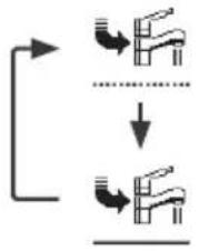
flowchart
graph TD
    A["Start"] --> B{Condition}
    B -->|Yes| C["Valve Icon"]
    B -->|No| D["Valve Icon"]
    C --> E["Downward Arrow"]
    D --> F["Downward Arrow"]
- Force DHW is turned off.
- Force DHW is turned on.
Note:
- Force DHW is disabled when Force Heater is turned on.
- When Force DHW is turned off, operation & mode should change back to the previous memorized status.

Powerful
Select this icon to operate the heating system powerfully.
Press ← to confirm your selection.
(The powerful operation starts approximately 1 minute after ← is pressed.)
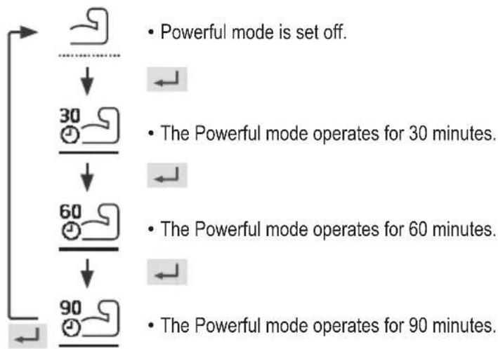
flowchart
graph TD
    A["Start"] --> B{Powerful mode is set off.}
    B --> C["30 minutes"]
    C --> D["The Powerful mode operates for 30 minutes."]
    D --> E["60 minutes"]
    E --> F["The Powerful mode operates for 60 minutes."]
    F --> G["90 minutes"]
    G --> H["The Powerful mode operates for 90 minutes."]
Note:
- Powerful is disabled when operation is turned OFF.

Quiet
Select this icon to operate quietly.
Press ← to confirm your selection.
(The quiet operation starts approximately 1 minute after ← is pressed.)
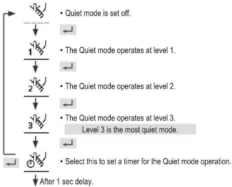
flowchart
graph TD
    A["Start"] --> B{Quiet mode is set off.}
    B --> C["Level 1"]
    C --> D{The Quiet mode operates at level 1.}
    D --> E["Level 2"]
    E --> F{The Quiet mode operates at level 2.}
    F --> G["Level 3"]
    G --> H{The Quiet mode operates at level 3. Level 3 is the most quiet mode.}
    H --> I["Select this to set a timer for the Quiet mode operation."]
    I --> J["After 1 sec delay."]
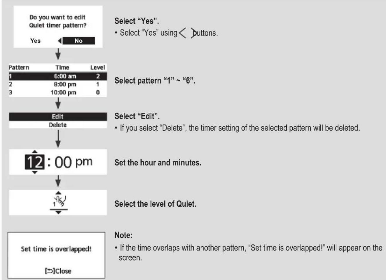
flowchart
graph TD
A["Do you want to edit Quiet timer pattern?"] --> B{Yes}
B -->|No| C["Select "Yes". Select "Yes" using < > buttons."]
C --> D["1 6:00 am 2"]
D --> E["2 8:00 pm 1"]
E --> F["3 10:00 pm 0"]
F --> G["Edit\nDelete"]
G --> H["12:00 pm"]
H --> I["Set the hour and minutes."]
I --> J["Select the level of Quiet."]
J --> K["Set time is overlapped!\n[→"]Close]

Force Heater
Select to force the Heater on.
Press ← to confirm your selection.
(The Force Heater mode starts approximately 1 minute after is pressed.)
- Force Heater is turned off.
- Force Heater is turned on.
Note:
- Force Heater is disabled whenever operation is already on and "Disabled due to operation ON!" will be displayed.
- It is not displayed when the outdoor unit is used alone, and when the heater is set to OFF even if the indoor unit is connected.
Disabled due to operation ON!
[→]Close

Weekly Timer
Select this icon to delete (cancel) or change the pre-set Weekly Timer.
Press ← to confirm your selection.
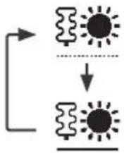
flowchart
graph TD
    A["Timer is set"] --> B["Timer is not ON"]
    B --> C["7"]
    C --> D["7"]
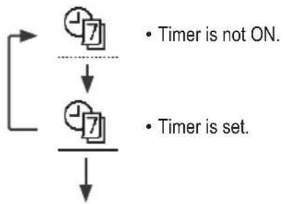
flowchart
graph TD
    A["Do you want to edit Weekly timer pattern?"] --> B{Yes}
    B -->|No| C["Timer setup"]
    C --> D["Timer copy"]
    D --> E["Sun Mon Tue Wed Thu Fri Sat"]
    E --> F{All 6 patterns are not set! Do you want to edit?}
    F -->|Yes| G["No"]
    F -->|No| H["End"]
Select "Yes".
- If you select "No", the screen will return to the Main Screen.
- Timer setup: Select Timer setup to edit the Weekly Timer.
- Timer copy: Select to copy a timer setting.
[Example of a Timer setup]
Select the day(s) which you wish to edit using ^buttons.
If all 6 patterns are not preset, this screen will be displayed.
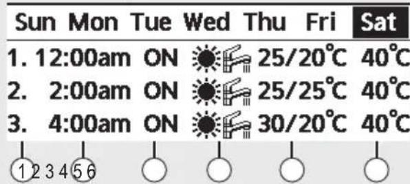
① Select pattern “1” \~ “6”.
② Set the hour and minutes of the Timer.
③ Select ON/OFF of the Timer.
④ Select the operation mode.
- Select mode using ^buttons.
⑤ Set the temperature for both Zone 1 and 2 (if your system has the 2-Zone setting).
![PANASONIC WH-WXG16ME8 - [Example of a Timer setup] - 2](/content/2026/04/699368/images/bc3bd5eeb77583d05fc10e7458c90374dfb1670325934b496cb4448cc46760a3.jpg)
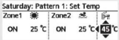
⑥ Set the Tank temperature.
Note:
- Timer is disabled when Force Heater is turned on or Heat-Cool SW is enabled.
- If you have preset the Weekly Timer on 2 zones, you must repeat the same procedure with Zone 2.

Force Defrost
Select to defrost the frozen pipes.
Press ← to confirm your selection.
(When the mode is accepted, below screen will be displayed.)
Request accepted!
[→]Close

Error Reset
Select to restore the previous settings when error has occurred.
Press ← to confirm your selection.
(When the mode has been accepted, below screen will be displayed.)
Request accepted!
[→]Close
- Make sure all units are turned off before selecting this mode which restores the whole system to the previous settings.

R/C Lock
Select to lock the Remote Controller.
Press ← to confirm your selection.
(When the mode has been accepted, below screen will be displayed.)
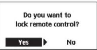
Select "Yes".
(The Main Screen will be locked.)
- If "No" is selected, the screen will return to the Main Screen.
To unlock the Remote Controller
Press any key.
(When the mode has been accepted, below screen will be displayed.)
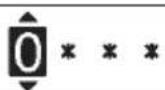
Enter any 4 digits of number (if the number is correct, the screen will be unlocked).
To reset forgotten password (under operation OFF screen)
Press , and continuously for 5 seconds.
(When the mode has been accepted, below screen will be displayed.)
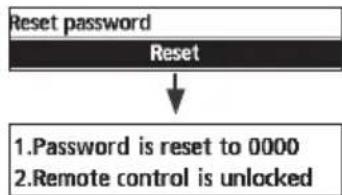
flowchart
graph TD
    A["Reset password"] --> B["Reset"]
    B --> C["1. Password is reset to 0000\n2. Remote control is unlocked"]
Select "Reset".
(The screen will be off after 3 seconds.)
Select menus and determine settings according to the system available in the household. All initial settings must be done by an authorised dealer or a specialist. It is recommended that all alterations of the initial settings are also done by an authorised dealer or a specialist.
• After initial installation, you may manually adjust the settings.
- The initial setting remains active until the user changes it.
- The Remote Controller can be used for multiple installations.
- Ensure the operation indicator is OFF before setting.
• The system may not work properly if set wrongly.
Please consult an authorised dealer/specialist.
To display

To select menu: ^ ∨ < >
To confirm the selected content:

![Main Menu 10:34am, Mon Function setup System check Personal setup Service contact Select [+] Confirm](/content/2026/04/699368/images/bc0edf3a79b740253abbc224d0af3ee3e4a4aed3058da04a7c68cc965ef10f11.jpg)
Menu Default Setting Setting Options / Display
1 Function setup
1.1 > Weekly timer
Once the weekly timer is set up, User can edit from Quick Menu. To set up to 6 patterns of operation on a daily basis.
- Disabled if Heat-Cool SW is select "Yes" or if Force Heater is on.
Timer setup
Select day of the week and set the patterns needed (Time / Operation ON/OFF / Mode)
Timer copy
Select day of the week
Weekly timer 10:34am, Mon
Sun Mon Tue Wed Thu Fri Sat
- 8:00am ON 40°C
2.12:00pm ON 24/28°C 40°C
- 1:00pm ON 12/10°C
Day Pattern [←]Edit
1.2 > Holiday timer
To save energy, a holiday period may be set to either turn OFF the system or lower the temperature during the period.
OFF
ON
OFF
>ON
Holiday start and end. Date and time
OFF or lowered temperature
Holiday: End 10:34am, Mon
Year/Month/Day Hour:Min

Select Confirm [←]
1.3 >Quiet timer
To operate quietly during the preset period.
6 patterns may be set.
Level 0 means the mode is off.
Time to start Quiet : Date and time
Level of quietness: 0 \~ 3
Quiet 10:34am, Mon
Pattern Time Level
| 1 | 8:00 am | 0 |
| 2 | 5:00 pm | 1 |
| 3 | 11:00 pm | 3 |
Select [←]Edit
| Menu Default Setting Setting Options / Display | ||
| 1.4 > Quiet priority | ||
| • To select priority during Quiet mode between Sound and Capacity.• If Sound priority is selected, unit will operate in quiet condition only.• If Capacity priority is selected, unit will operate in quiet condition but it will prioritize on providing required capacity at the same time. | Sound | 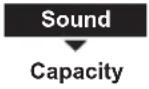 |
| 1.5 > *1 Room heater | ||
| To set the room heater ON or OFF. | OFF | 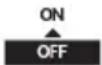 |
| 1.6 > *2 Tank heater | ||
| To set the tank heater ON or OFF. | OFF | ON |
| 1.7 > *2 Sterilization | ||
| To set the auto sterilization ON or OFF. | ON |  |
| • Do not use the system during sterilization in order to prevent scalding with hot water, or overheating of shower.• Ask an authorised dealer/specialist to determine the level of sterilization function field settings according to the local laws and regulations. | ||
| 1.8 > *3 DHW mode (Domestic Hot Water) | ||
| To set the DHW mode to Standard or Smart.• Standard mode have faster DHW Tank heat up time. Meanwhile Smart mode take longer time to heat up DHW time with lower energy consumption. | Standard | 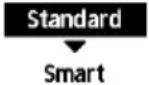 |
| To set the tank sensor to Top or Center.• Selection of the tank sensor to top slow down the start of boiling up the tank and reduce power consumption.Please change this selection to “Center” when the hot water becomes insufficient. | Top |  |
*1 It is not displayed when the outdoor unit is used alone or depending on the settings.
^*2 Only displayed when Tank connection is Yes.
*3 Only displayed when connect Panasonic AIR-TO-WATER HYDROMODULE+TANK.
Menu Default Setting Setting Options / Display
| 2 System check | ||
| 2.1 > Energy monitor | ||
| Present or historical chart of energy consumption, generation or COP. | PresentSelect and retrieve | Total consumption (1year)0.0kWh1year 1 2 3 4 5 6 7 8 9 1 0 1 CMBJan, 2024: 0.0 kWh Approx. Month Mode *6 |
| Historical chartSelect and retrieve | ||
| ·COP= Coeffi cient of Performance.·For historical chart, the period is selected from 1 day/1 week/1year.·Energy consumption (kWh) of heating, *1, *2 cooling, *5 tank and total may be retrieved.·The total power consumption is an estimated value based on AC 230 V and may differ from value measured by precise equipment. | ||
| 2.2 >*3 System information | ||
| Shows all system information in each area. | Actual system information of 11 items:Inlet / Outlet / Zone 1 / Zone 2 / Tank /Buffer tank / Solar / Pool / COMPfrequency / Pump flowrate / Water pressure*7 Select and retrieve | System information 10:34am, Mon1. Inlet : 0°C2. Outlet : 0°C3. Zone 1 : 0°C4. Zone 2 : 0°CPage |
| 2.3 >Error history | ||
| ·Refer to Troubleshooting for error codes.·The most recent error code is displayed at the top. | Select and retrieve | Error history 10:34am, Mon1. --2. --3. --4. --[--]Clear history |
| 2.4 >Compressor | ||
| Shows the compressor performance. | Select and retrieve | Compressor 10:34am, Mon1. Current frequency : 0 Hz2. (OFF-ON) counter : 03. Total ON time : 0 h[→]Back |
| 2.5 >Heater | ||
| Total hours of ON time for *4 Room heater/ *5 Tank heater. | Select and retrieve | Heater 10:34am, MonTotal ON time: Oh[→] Back |
(NOTE) : If [Approx.] is shown on Energy Monitor display, data displayed on the remote controller is obtained through heat pump's internal calculation.
If [Approx.] is NOT shown on Energy Monitor display, data** displayed on the remote controller is obtained by External Meters.
Data stored on the Aquarea unit can be mixed between internal calculation and External Meters.
**In order to know the exact consumption or generation, please use as reference always the External Meters' data.
*1 The system is locked to operate without COOL mode. It can be unlocked only by authorised installers or our authorised service partners.
*2 Only displayed when COOL mode is unlocked (This means when COOL mode is available).
*3 The items displayed differ depending on the Appliance and connected units.
*4 It is not displayed when the outdoor unit is used alone.
*5 Only displayed when Tank connection is Yes.
*6 If [Approx.] is shown on Energy Monitor display, data displayed on the remote controller is obtained through heat pump's internal calculation.
If [Approx.] is NOT shown on Energy Monitor display, data displayed on the remote controller is obtained by External Meters.
*7 Only displayed when each connection is Yes.
Menu Default Setting Setting Options / Display
| 3 Personal setup | |||
| 3.1 > Remote control No. | |||
| • To display remote control number of a particular remote controller so that installer and end user are well informed.• Main remote controller is displayed as RC-1. Second remote controller is displayed as RC-2. | Select and retrieve | RC No. 10:34am,Mon [←] Confirm [←] Confirm | |
| 3.2 > Touch sound | |||
| Turns the operation sound. | 3 OFF / 1 / 2 / 3 / 4 | Touch sound 9:53am,MonLevel  | |
| 3.3 > LCD contrast | |||
| Sets the screen contrast. | 3 | 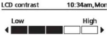  | |
| 3.4 > Backlight | |||
| Sets the duration of screen backlight. | 1 min |   | |
| 3.5 > Backlight intensity | |||
| Sets screen backlight brightness. | 4 | 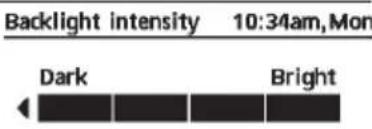 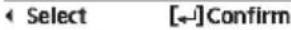 | |
| 3.6 > *1 Clock format | |||
| Sets the type of clock display. | am/pm |   | |
| 3.7 > Date & Time | |||
| Sets the present date and time. | Year / Month / Day / Hour / Min | 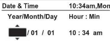  | |
*1 The default setting is am/pm, but 24h is displayed on the selection screen.
| Menu Default Setting Setting Options / Display | |||
| 3.8 >Language | |||
| Sets the display language for the top screen. | ENGLISH / FRANÇAIS / DEUTSCH / ITALIANO / ESPAÑOL / DANISH / SWEDISH / NORWEGIAN / POLISH / CZECH / NEDERLANDS / TÜRKÇE / SUOMI / MAGYAR / SLOVENŠČINA / HRVATSKI / LIETUVIŲ / PORTUGUĖS / БЪЛГАРСКИ / EESTI / LATVIEŠU / ROMÂNĂ / SHQIP / SLOVENČINA / MAKEDОНСКИ / УКРАЇНСЬКА / ЕЛАННИКА | Language 10:34am, Mon | |
| ENGLISH | |||
| FRANÇAIS | |||
| DEUTSCH | |||
| ITALIANO | |||
| Select [←] Confirm | |||
| 3.9 >Unlock password | |||
| 4 digit password for all the settings. | 0000 | Unlock password 10:34am, Mon | |
 | |||
| Select [←] Confirm | |||
| 4 Service contact | |||
| 4.1 >Contact 1 / Contact 2 | |||
| Preset contact number for installer. | Select and retrieve | Service setup 10:34am, Mon | |
| Contact 1 | |||
| Name : Bryan Adams | |||
 : 08812345678 : 08812345678 | |||
| Select | |||
Menu Default Setting Setting Options / Display
5 Installer setup System setup
5.1 > \*1 Optional PCB connectivity
| To connect to the external PCB required for servicing. | No | YesNo |
- If the external PCB is connected (optional), the system will have following additional functions:
① Control over 2 zones (including the swimming pool and the function to heat water in it).
② Solar function (the solar thermal panels connected to either the DHW (Domestic Hot Water) Tank or the Buffer Tank.
• DHW is not applicable for WH-ADC *models.
③ External compressor switch.
④ External error signal.
⑤ SG ready control.
⑥ Demand control.
⑦ Heat-Cool SW
5.2 > Zone & Sensor
| To select the sensors and to select either 1 zone or 2 zone system. | Zone | Zone & Sensor 10:34am, Mon |
| After selecting 1 or 2 zone system, proceed to the selection of room or swimming pool.If the swimming pool is selected, the temperature must be selected for T temperature between 0^ 10^ . | Zone1 Zone system2 Zones systemSelect [←] Confirm | |
| Sensor | ||
| * For room thermostat, there is a further selection of external or internal.If select internal, there is a further selection of RC-1 or RC-2 (only available when Zone selection is 1 zone system).Select RC-1 if main remote controller's thermistor is to be used for room temperature control and vice versa. | Zone & Sensor 10:34am, MonSensorWater temperatureRoom thermostatRoom thermistorSelect [←] Confirm |
5.3 > \*1 Heater capacity
| To reduce the heater power ifunnecessary.*3 kW / 6 kW / 9 kW* Options of kW vary dependingon the model. | Heater capacity 10:34am,Mon3 kW[-]Confirm |
5.4 > Anti freezing
| To activate or deactivate the water freeze prevention when the system is OFF | Yes |
5.5 > \*2 Tank connection
| To connect tank to the system. | No | YesNo |
*1 It is not displayed when the outdoor unit is used alone.
*2 It is not displayed when connect Panasonic AIR-TO-WATER HYDROMODULE+TANK.
| Menu Default Setting Setting Options / Display | |||
| 5.6 >*1 DHW capacity | |||
| To select tank heating capacity to variable or standard. Variable capacity heat up tank with fast mode and keep the tank temperature with effi cient mode. While standard capacity heat up tank with rated heating capacity. | Variable |  | |
| 5.7 >*2 Buffer tank connection | |||
| To connect tank to the system and if selected YES, to set △T temperature. | No | Yes  | |
| >Yes | |||
| 5 °C | Set △T for Buffer Tank | Buffer tank 10:34am,Mon △T for Buffer tank Range: (0°C~10°C) Steps: ±1°C  Select Confirm[-] Select Confirm[-] | |
| 5.8 >*1 Tank heater | |||
| To select external or internal tank heater and if External is selected, set a timer for the heater to come on.* This option is available if Tank connection is selected (YES). | External | Tank heater 10:34am,Mon  Select Confirm[-] Select Confirm[-] | |
| >External | |||
| 1:30 | Tank heater 10:34am,Mon Tank heater: ON time Range: (0:20~3:00) Steps: ±0:05  Select Confirm[-] Select Confirm[-] | ||
| 5.9 >Base pan heater | |||
| To select whether or not optional base pan heater is connected.* Type A - The base pan heater activates only during deice operation.* Type B -The base pan heater activates when outdoor ambient temperature is 5 °C or lower. | No |  | |
| >Yes | |||
| A | Set base pan heater type*. Base pan heater type 10:34am,Mon  Select [-] Confirm Select [-] Confirm | ||
| 5.10 >*3 Alternative outdoor sensor | |||
| To select an alternative outdoor sensor. | No | Yes  | |
*1 Only displayed when Tank connection is Yes.
*2 It is not displayed when the outdoor unit is used alone and Panasonic AIR-TO-WATER HYDROMODULE+TANK 2 Zone model.
*3 It is not displayed when the outdoor unit is used alone.
| Menu Default Setting Setting Options / Display | ||
| 5.11 > Bivalent connection | ||
| To select to enable or disable bivalent connection. | No |  |
| > Yes | ||
| To select either auto control pattern or SG ready input control pattern or smart control pattern.* This selection only display to select when optional pcb connection set to Yes. | Auto |  |
| To select a bivalent connection to allow an additional heat source such as a boiler to heat-up the buffer tank and domestic hot water tank when heatpump capacity is insufficient at low outdoor temperature. The bivalent feature can be set-up either in alternative mode (heatpump and boiler operate alternately), or in parallel mode (both heatpump and boiler operate simultaneously), or in advance parallel mode (heatpump operates and boiler turns on for buffer-tank and/or domestic hot water depending on the control pattern setting options). | > Yes > Auto | |
| -5 °C | Set outdoor temperature for turn ON Bivalent connection. | |
| Yes > After selecting the outdoor temperature | ||
| Control pattern | ||
| Alternative / Parallel / Advanced parallel | ||
| • Select advanced parallel for bivalent use of the tanks. | ||
| Control pattern > Alternative | ||
| OFF | Option to set external pump either ON or OFF during bivalent operation. Set to ON if system is simple bivalent connection. | |
| Control pattern > Advanced parallel | ||
| Heat Selection of the tank | ||
| • “Heat” implies Buffer Tank and “DHW” implies Domestic Hot Water Tank. | ||
| Control pattern > Advanced parallel > Heat Yes | ||
| • Buffer Tank is activated only after selecting “Yes”. | ||
| -8 °C | Set the temperature threshold to start the bivalent heat source. | |
| Menu Default Setting Setting Options / Display | |||
Menu Default Setting Setting Options / Display
| >Yes >Smart >After selecting for the external pump >Energy price | ||
| - Select Electricity to set on electricity price.- Select Boiler to set on boiler price and its effi ciency. | Bivalent connection 10:34am,MonEnergy price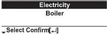 | |
| >Yes >Smart >After selecting for the external Electricity |  Bivalent connection 10:34am,Mon Bivalent connection 10:34am,Mon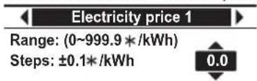 | |
| 0.0 * / kWh- There are total 10 different prices can be set for Electricity:Electricity price 1 ~ Electricity price 10- Range is 0 ~ 999.9 * / kWh- Press or to enter a setting screen as shown in Figure 1. Then start setting the value of electricity price.- After fi nish setting a particular electricity price (eg. Electricity price 1), press <or to go and set for other electricity price.* Set the price according to value provided by electrical supply company. |  Figure 1 Figure 1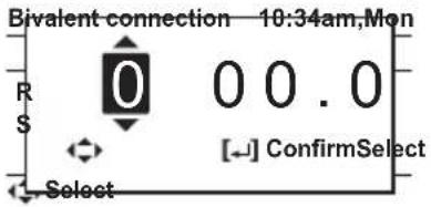 | |
| >Yes >Smart >After selecting for the external pump >Energy price >Boiler | ||
| 0.0 * / kWh- Refer to method of Electricity price setting above for setting of boiler price.- After fi nish setting of boiler price, set the boiler effi ciency (Range : 0 ~ 99%).0%* Set the price according to value provided by boiler or gas supply company. | Bivalent connection 10:34am,MonBoiler priceRange: (0~999.9 * /kWh)Steps: ±0.1*/kWhSelect Confirm[-]Bivalent connection 10:34am,MonBoiler efficiencyRange: (0~99%)Steps: ±1%Select Confirm[-] | |
Remark: * Currency setting depends on where you use this product.
Menu Default Setting Setting Options / Display
Yes > Smart > After selecting for the external pump > Schedule > Season setting
| Season 1 : Dec (Refers to Winter season) | Bivalent connection 10:34am,Mon |
| Schedule | |
| Season 2 : Mar (Refers to Spring season) | Season setting |
| Schedule setting | |
| Season 3 : Jun (Refers to Summer season) | Select Confirm[←] |
| Season 4 : Oct (Refers to Autumn season) | Bivalent connection 10:34am,Mon |
| - There are total 4 seasons to be set | Season 1: Start month |
| - Set the starting month for each season. | Range: (Jan~Dec) |
| (Eg. when Season 1 is set to Dec and Season 2 is set to Mar, month of December to February will be treated as Season 1). | Steps: ±1month |
| Select Confirm[←] |
Yes > Smart > After selecting for the external pump > Schedule > Schedule setting
| Start time (Pattern 1) : 3:00am | Bivalent connection 10:34am,Mon |
| Start time (Pattern 2) : 9:00am | Schedule setting |
| Start time (Pattern 3) : 4:00pm | Season 1 |
| Start time (Pattern 4) : 9:00pm | Season 2 |
| - For each season, there are total 4 patterns can be set. | Season 3 |
| Select Confirm[←] |
Price (Pattern 1/2/3/4) : 1
- Set the target start time and the appropriate electricity price for each pattern.
- Select "1" to edit both start time and electricity price. Select "2" to edit electricity price only.
| Season 1 | 10:34am,Mon | |
| Start time | Price(*/kWh) | |
| 1. | 3:00am | 0.0 |
| 2. | 9:00am | 0.0 |
| 3. | 4:00pm | 0.0 |
| Select Edit [←] | ||
| Bivalent connection 10:34am,Mon | |
| Sc | Select |
| 1: To edit time & price | |
| 2: To edit price only | |
| 1 | 2 |
| Select Confirm | |
Menu Default Setting Setting Options / Display
| - Range of start time displayed can be in “24h” or “am/pm” format depend on setting of “Clock format”. | Season 1 10:34am,Mon | |
| Pattern 1: Start time | ||
| Range: (0.00~23.00)Steps: ±1hour3.00 | ||
| Select Confirm[←] | ||
| - Range of electricity price is 0 ~ 10 which refers back to the 10 different electricity price set previously (under “Energy price > Electricity”: Electricity price 1 ~ Electricity price 10). The price displayed on the upper right corner indicates the previous set value of Electricity price 1 to Electricity price 10.* When the price is set to “0”, the electricity price will be treated as 0.0 * / kWh. It is for the convenience of installer when 0.0 is the desired setting value for a particular time. | Season 1 10:34am,Mon | |
| Pattern 1: Price /kWh 0.0 * | ||
| Range: (0~10)Steps: ±10 | ||
| Select Confirm[←] |
5.12 > * External SW
| No |  | |
| 5.13 >*2 Solar connection | ||
| The optional PCB connectivity must be selected YES to enable the function.If the optional PCB connectivity is not selected, the function will not appear on the display.DHW is not applicable for WH-ADC models. | No |  |
| >Yes | ||
| Buffer tank Selection of the tank | Solar connection 10:34am,Mon Select [-]Confirm Select [-]Confirm | |
| >Yes >After selecting the tank | ||
| 10°C | Set △T ON temperature Solar connection 10:34am,Mon△T Turn ONRange: (6°C~15°C)Steps: ±1°C  Select [-]Confirm Select [-]Confirm | |
| >Yes >After selecting the tank >ON temperature | ||
| 5°C | Set △T OFF temperature Solar connection 10:34am,Mon△T Turn OFFRange: (2°C~9°C)Steps: ±1°C  Select [-]Confirm Select [-]Confirm | |
*1 It is not displayed when the outdoor unit is used alone.
*2 It is not displayed when the outdoor unit is used alone and Panasonic AIR-TO-WATER HYDROMODULE+TANK 2 Zone model.
Menu Default Setting Setting Options / Display
| >Yes >After selecting the tank >T.ON temperature T.OFF temperature | |||
| 5°C | Set Antifreeze temperature | Solar connection 10:34am, Mon Anti freeze Range: (-20°C~10°C) Steps: ±1°C  Select [-] Confirm Select [-] Confirm | |
| >Yes >After selecting the tank >T.ON temperature T.OFF temperature >After setting the antifreeze temperature | |||
| 80°C Set Hi limit | 80°C Set Hi limit | Solar connection 10:34am, Mon Hi limit Range: (70°C~90°C) Steps: ±5°C  Select [-] Confirm Select [-] Confirm | |
| 5.14 >*1 External error signal | |||
| No | Yes No | ||
| 5.15 >*1 Demand control | |||
| No | Yes No | ||
| 5.16 >*1 SG ready | |||
| No | Yes No | ||
| >Yes >After selecting Capacity | |||
| 120% | SG ready 10:34am, Mon Capacity [1-0]: DHW Range: (50%~150%) Steps: ±5% 120% Select [-] Confirm | ||
| >Yes >After selecting Power consumption >*HPU stop consumption | |||
| *2,*4 3.6kW | *HPU stop consumption | SG ready 10:34am, Mon HPU stop consumption Range: (0.5kW~10.0kW) Steps: ±0.1kW 3.6 Select Confirm[-] | |
| >Yes >After selecting *HPU stop consumption >Consumption | |||
| *3 3.6kW | Consumption (1) & (2) of DHW (in kW), Heat (in kW) and Cool (in kW) | SG ready 10:34am, Mon Consumption [1-0]: DHW Range: (0.5kW~10.0kW) Steps: ±0.1kW 3.6 Select Confirm[-] | |
Remark: * HPU means Heat pump unit (Outdoor unit).
*1 It is not displayed when the outdoor unit is used alone.
^*2 Depending on the model, it may be less than 3.6kW.
*3 Depending on the model, it may be less than 3.6kW or more than 3.6kW.
*4 Even though the setting value is lower than 3.0kW, actual power consumption can be 3.0kW caused by back-up heater operation.
| Menu Default Setting Setting Options / Display | ||
| 5.17 >*1 External compressor SW | ||
| No | 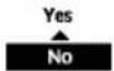 | |
| >Yes | ||
| Heat source | Ext. compressor SW 11:34am,MonHeater *Select Confirm[--] *Select Confirm[--] | |
| 5.18 >Circulation liquid | ||
| To select whether to circulate water or glycol in the system. | Water | Circulation liquid 10:34am,Mon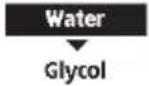 Select [--]Confirm Select [--]Confirm |
| 5.19 >*1, *2 Heat-Cool SW | ||
| No |  | |
| 5.20 >*1 Force heater | ||
| To turn on Force heater either manually (by default) or automatically. | Manual | Force heater 10:34am,MonAuto ^Select [--]Confirm ^Select [--]Confirm |
| 5.21 >Force defrost | ||
| If auto selection is set, outdoor unit will start defrost operation if long heating hour operate during low outdoor temperature. | Manual | 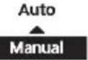 |
| 5.22 >*1 Defrost signal | ||
| To turn on defrost signal to stop fan coil during defrost operation.(If defrost signal set to yes, bivalent function will not available to use) | No |  |
*1 It is not displayed when the outdoor unit is used alone.
*2 Only displayed when COOL mode is unlocked. (This mean when COOL mode is available)
| Menu Default Setting Setting Options / Display | ||
| 5.23 > Pump fl owrate | ||
| To set variable flow pump control or fi x pump duty control. | △T | 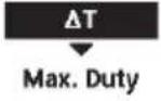 |
| 5.24 > DHW Defrost | ||
| Allow system to run defrost by using hot water instead of room unit for better room comfort. | Yes |  |
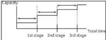
| 5.25 > Heating control | ||
| To select unit operation condition whether to achieve set temperature faster or to save energy.When "Efficiency" is selected, the time setting will transition to 1st, 2nd, and 3rd stage.Increasing the time will slowly increase the capacity. | Comfort | Comfort |
| > Efficiency | ||
| 0:20 | Heating control 10:34am,MonEfficiency: Stage 1Range: (0:00~1:00)Steps: ±0:05  Select Confirm[-] Select Confirm[-] | |
 | ||
| 5.26 > External meter | ||
| To set which external meter to be used depends on meter connection.There are generation meters and various types of electricity meters.For generation meters, there are two connection systems :-a) One generation meter system :Heat-cool meter onlyb) Two generation meter system :Heat-cool meter and Tank meter | Heat-cool meter : No* Tank meter : NoElec. meter HP : NoElec. meter 1 (PV) : NoElec. meter 2 (Building) : NoElec. meter 3 (Reserve) : No* Only available if both Heat-cool meter and Tank connection are set to Yes. | External meter 10:34am,MonHeat-Cool meterTank meterElec. meter HPElec. meter 1 (PV)Select Confirm[-]External meter 10:34am,MonElec. meter HPElec. meter 1 (PV)Elec. meter 2 (Building)Elec. meter 3 (Reserve)*Select Confirm[-] |
| > Heat-cool meter | ||
| - Set Heat-cool meter to Yes when this generation meter is connected.- It is to measure energy generation of heat pump unit during heating and cooling only operation (one generation meter system) or during heating, cooling and DHW operation (two generation meter system). |  | |
Remark: Elec. means "Electricity"
HP means "Heat pump"
Menu Default Setting Setting Options / Display
| > Tank meter | ||
| - Set Tank meter to Yes when this generation meter is connected.- It is to measure energy generation of heat pump unit during DHW operation*.* Only available if both Heat-cool meter and Tank connection are set to Yes.Only set Tank meter to Yes when the connection is two generation meter system. | YesNo | |
| > Elec. meter HP | ||
| - Set Elec. meter HP to Yes when this electricity meter is connected.- It is to measure energy consumption of heat pump unit. | YesNo | |
| > Elec. meter 1 (PV) | ||
| - Set Elec. meter 1 (PV) to Yes when this electricity meter is connected.- It is to measure energy generation of solar system. This data will be displayed only on Cloud system. | YesNo | |
| > Elec. meter 2 (Building) | ||
| - Set Elec. meter 2 (Building) to Yes when this electricity meter is connected.- It is to measure energy consumption of the building. This data will be displayed only on Cloud system. | YesNo | |
| > Elec. meter 3 (Reserve) | ||
| - Set Elec. meter 3 (Reserve) to Yes when this electricity meter is connected.- It is to measure energy consumption. This data will be displayed only on Cloud system. | YesNo |
5.27 > Electrical anode
| To enable or disable operation of electrical anode. | Yes (for -AN models)No (for non -AN models)Yes : displayNo : no displayerror : blinking | 40°C | YesNo |
Remark: Elec. means "Electricity"
HP means "Heat pump"
Menu Default Setting Setting Options / Display
5.28 > * Extra pump
| Selects whether the extra pump is used in the circulation circuit for heating or in the circulation circuit for DHW, or it is not used. If set to “No”, the pump is not used. If set to “Heat”, the extra pump is used as a pump for the circulation circuit (for heating/ cooling). If set to “DHW”, the extra pump circulates domestic hot water in the circuit for DHW to prevent the domestic hot water from getting cold. - If set to “Comfort”, hot water is continuously circulated during DHW operation. - If set to “Effi ciency”, the extra pump turns ON and OFF alternatively following ON/OFF time setting. | No | No Heat DHW | |
| >DHW | |||
| 8:00 am / 8:00 Set Pump ON time | DHW 11:34pm,MonPump ON time8:00 amSelect [-] Confirm | ||
| 8:00 pm / 20:00 Set Pump OFF time | DHW 11:34pm,MonPump OFF time8:00 pmSelect [-] Confirm | ||
| Effi ciency | Select Comfort or Effi ciency | DHW 11:34pm,MonComfortEfficiencySelect Confirm | |
| >DHW >After selecting Effi ciency | |||
| 0:15 Set ON time | DHW 11:34pm,MonON timeRange: (0:05~1:00)Steps: ±0:050:15Select Confirm | ||
| 0:15 Set OFF time | DHW 11:34pm,MonOFF timeRange: (0:05~1:00)Steps: ±0:050:15Select Confirm | ||
5.29 > External heater
| Set to “YES” after an external heater is installed.(This menu is only displayed for the Control Module model (indoor unit)) | No |
5.30 > Static pressure
| If set to “No”, the fans in the outdoor unit rotate at a normal speed.If set to “YES”, the fans in the outdoor unit rotate at a higher speed than normal for response to high static pressure. | No |
*1 It is not displayed when the outdoor unit is used alone.
Menu Default Setting Setting Options / Display
5.31 > *1 Cooling capacity
| Selects the cooling capacity. If set to “Efficiency”, the cooling operation is performed at rated capacity for efficient cooling. If set to “Comfort”, the cooling operation is performed at maximum capacity. | Efficiency | |
| 6 Installer setup Operation setup | ||
| To access to the four major functions or modes. | 4 main modesHeat / *1, *2 Cool / *1, *2 Auto / *3 Tank | Operation setup 10:34am, MonHeatCoolAutoTankSelect [-/-] Confirm |
| 6.1 > Heat | ||
| To set various water & ambient temperatures for heating. | Water temp. for heating ON /Outdoor temp. for heating OFF /△T for heating ON /Heater ON/OFF | Operation setup 10:34am, MonHeatWater temp. for heating ONOutdoor temp. for heating OFF△T for heating ONSelect [-/-] Confirm |
| > Water temp. for heating ON | ||
| Compensation curve | Operation setup 10:34am, MonHeat ON: Water temp.Compensation curveDirectSelect [-/-] Confirm | |
| > Water temp. for heating ON > Compensation curve | ||
| X axis: -5 °C, 15 °CY axis: 55 °C, 35 °C | Input the 4 temperature points (2 on horizontal X axis, 2 on vertical Y axis).Heat ON: Water temp.:Zone155°C7535°C-20155°C15°C[←]- [←] ConfirmSelect | |
| Temperature range: X axis: -20 °C ~ 15 °C, Y axis: See belowTemperature range for the Y axis input:WH-WXG model: 25 °C ~ 75 °CRegardless of the above setting, there is a limit to the water temperature. Refer to the operating condition on page 3.If 2 zone system is selected, the 4 temperature points must also be input for Zone 2."Zone 1" and "Zone 2" will not appear on the display if only 1 zone system. | ||
| > Water temp. for heating ON > Direct | ||
| 35 °C | Temperature for heating ONOperation setup 10:34am, MonHeat ON: Water temp.:Zone2Range: (25°C~75°C)Steps: ±1°C35°CSelect Confirm[-/-] | |
| Min. ~ Max. range is 25 °C ~ 75 °C:WH-WXG model: 25 °C ~ 75 °CRegardless of the above setting, there is a limit to the water temperature. Refer to the operating condition on page 3.If 2 zone system is selected, temperature set point must input for Zone 2."Zone 1" and "Zone 2" will not appear on the display if only 1 zone system. | ||
*1 The system is locked to operate without COOL mode. It can be unlocked only by authorised installers or our authorised service partners.
*2 Only displayed when COOL mode is unlocked (This means when COOL mode is available).
*3 Only displayed when Tank connection is Yes.
Menu Default Setting Setting Options / Display
| >Outdoor temp. for heating OFF | |||
| >Outdoor temp. for heating OFF >Heat OFF outdoor temp. | |||
| 24°C | Set outdoor temp to stop heating.Setting range is 6°C~35°C | Operation setup 10:34am, Mon Heat OFF: Outdoor temp.Range: (6°C~35°C)Steps: ±1°C  Select [-] Confirm Select [-] Confirm | |
| >Outdoor temp. for heating OFF >Heat ON outdoor temp. | |||
| 23°C | Set outdoor temp to start heating.Setting range is 5°C~X°C (X is heating OFF temp. -1) | Operation setup 10:34am, Mon Heat ON: Outdoor temp.Range: (5°C~23°C)Steps: ±1°C  Select Confirm[-] Select Confirm[-] | |
| >Outdoor temp. for heating OFF >Heat ON Delay time. | |||
| 0:30 min | Set delay time from heating OFF to heating ON. | Operation setup 10:34am, Mon Heat ON: Delay timeRange: (0:30~24:00)Steps: ±0:30  Select Confirm[-] Select Confirm[-] | |
| >Δ for heating ON | |||
| 5°C | Set ΔT for heating ON.* This setting will not available to set when pump flowrate set to Max. duty. | Operation setup 10:34am, Mon Heat ON: ΔTRange: (1°C~15°C)Steps: ±1°C  Select [-] Confirm Select [-] Confirm | |
| >*1 Heater ON/OFF | |||
| >Heater ON/OFF >Outdoor temp. for heater ON | |||
| 0°C | Temperature for heater ON | Operation setup 10:34am, Mon Heater ON: Outdoor temp.Range: (-20°C~15°C)Steps: ±1°C  Select [-] Confirm Select [-] Confirm | |
| >Heater ON/OFF >Delay time for heater ON | |||
| 0:30 min | Delay time for heater to turn on | Operation setup 10:34am, Mon Heater ON: Delay timeRange: (0:10~1:00)Steps: ±0:10  Select [-] Confirm Select [-] Confirm | |
| >Heater ON/OFF >Water temperature for heater ON | |||
| -4°C | Setting of water temperature to turn on from water set temperature. | Operation setup 10:34am, Mon Heater ON: ΔT of target Temp.Range: (-10°C~2°C)Steps: ±1°C  Select [-] Confirm Select [-] Confirm | |
*1 It is not displayed when the outdoor unit is used alone.
| Menu Default Setting Setting Options / Display | ||
| >Heater ON/OFF >Water temperature for heater OFF | ||
| -2°C | Setting of water temperature to turn off from water set temperature. Operation setup 10:34am, MonHeater OFF: ΔT of target Temp.Range: (-8°C~0°C)Steps: ±1°C  Select [-] Confirm Select [-] Confirm  | |
| 6.2 >*1, *2 Cool | ||
| To set various water & ambient temperatures for cooling. | Water temperatures for cooling ON and △T for cooling ON. | Operation setup 10:34CoolWater temp. for cooling ON  ΔT for cooling ON ΔT for cooling ON  Select [-] Confirm Select [-] Confirm  |
| >Water temp. for cooling ON | ||
| Compensation curve | Cooling ON temperatures in compensation curve or direct input. Operation setup 10:34Cool ON: Water temp.Compensation curveDirect   Select [-] Confirm Select [-] Confirm   | |
| >Water temp. for cooling ON >Compensation curve | ||
| X axis: 20°C, 30°CY axis: 15°C, 10°C | Input the 4 temperature points (2 on horizontal X axis, 2 on vertical Y axis) Cool ON: Water temp: Zone  15°C 2010°C 15°C 2010°C  10°C 10°C  5 15 20°C 30°C [677D]Select [-] Confirm [30TH]W7GC 5 15 20°C 30°C [677D]Select [-] Confirm [30TH]W7GC | |
| • If 2 zone system is selected, the 4 temperature points must also be input for Zone 2. “Zone 1” and “Zone 2” will not appear on the display if only 1 zone system. | ||
| >Water temp. for cooling ON >Direct | ||
| 10°C | Set temperature for Cooling ON Operation setup 10:34Cool ON: Water temp.: Zone Range: (5°C~20°C) Steps: ±1°C [6TSC]  [G03Y] [G03Y]  Select [-] Confirm Select [-] Confirm   | |
| • If 2 zone system is selected, temperature set point must input for Zone 2. “Zone 1” and “Zone 2” will not appear on the display if only 1 zone system. | ||
| >△T for cooling ON | ||
| 5°C | Set △ for cooling ON * This setting will not available to set when pump flowrate set to Max. duty. Operation setup 10:34Cool ON: ΔT  [GXSG]Range: (1°C~15°C) Steps: ±1°C [GXSG]Range: (1°C~15°C) Steps: ±1°C  [XGHS] [XGHS] Select [-] Confirm Select [-] Confirm  [3TB5] [3TB5] | |
Menu Default Setting Setting Options / Display
| 6.3 >*1, *2 Auto | |||
| Automatic switch from Heat to Cool or Cool to Heat. | Outdoor temperatures for switching from Heat to Cool or Cool to Heat. Outdoor temp. for (Heat to Cool) / Outdoor temp. for (Cool to Heat) | Operation setup 10:34am, Mon AutoOutdoor temp. for (Heat to Cool)Outdoor temp. for (Cool to Heat)Select [-] Confirm | |
| >Outdoor temp. for (Heat to Cool) | |||
| 15 °C | Set outdoor temperature for switching from Heat to Cool. | Operation setup 10:34am, MonAuto: Outdoor temp.(Heat to Cool)Range: (11°C~25°C)Steps: ±1°C  Select [-] Confirm Select [-] Confirm | |
| >Outdoor temp. for (Cool to Heat) | |||
| 10 °C | Set outdoor temperature for switching from Cool to Heat. | Operation setup 10:34am, MonAuto: Outdoor temp.(Cool to Heat)Range: (5°C~14°C)Steps: ±1°C  Select [-] Confirm Select [-] Confirm | |
| 6.4 >*3 Tank | |||
| Setting functions for the tank. | Floor operation time (max) / Tank heat up time (max) / Tank re-heat temp. / Sterilization | Operation setup 10:34am, MonTankFloor operation time (max)Tank heat up time (max)Tank re-heat temp.Select [-] Confirm | |
| The display will show 3 functions at a time. | |||
| >Floor operation time (max) | |||
| 8:00 | Maximum time for floor operation (in hours and minutes) | Operation setup 10:34am, MonTank: Floor ope. time (max)Range: (0:30~10:00)Steps: ±0:30  Select [-] Confirm Select [-] Confirm | |
| >Tank heat up time (max) | |||
| 1:00 | Maximum time for heating the tank (in hours and minutes) | Operation setup 10:34am, MonTank: Heat up time (max)Range: (0:05~4:00)Steps: ±0:05  Select [-] Confirm Select [-] Confirm | |
| >Tank re-heat temp. | |||
| -8 °C | Set temperature to perform reboil of tank water. | Operation setup 10:34am, MonTank: Re-heat temp.Range: (-12°C~-2°C)Steps: ±1°C  Select [-] Confirm Select [-] Confirm | |
*1 The system is locked to operate without COOL mode. It can be unlocked only by authorised installers or our authorised service partners.
*2 Only displayed when COOL mode is unlocked (This means when COOL mode is available).
* Only displayed when Tank connection is Yes.
Menu Default Setting Setting Options / Display
| > Sterilization | ||||||||
| Monday | Sterilization may be set for 1 or more days of the week.Sun / Mon / Tue /Wed / Thu / Fri / Sat | Operation setup 10:34am,MonSterilization: Day | ||||||
| Sun | Mon | Tue | Wed | Thu | Fri | |||
| - | ✓ | - | - | - | - | |||
| Day | [←] Confirm | |||||||
| > Sterilization: Time | ||||||||
| 12:00 | Time of the selected day(s) of the week to sterilize the tank0:00 ~ 23:59 | Operation setup 10:34am,MonSterilization: Time12:00 pmSelect [←]Confirm | ||||||
| > Sterilization: Boiling temp. | ||||||||
| 65 °C | Set boiling temperatures for sterilize the tank. | Operation setup 10:34am,MonSterilization: Boiling temp.*1Range: (55°C~65°C)Steps: ±1°C65 °CSelect [←]Confirm | ||||||
| > Sterilization: Ope. time (max) | ||||||||
| 0:10 | Set sterilizing time (in hours and minutes) | Operation setup 10:34am,MonSterilization: Ope. time (max)Range: (0:05~1:00)Steps: ±0:050:10Select [←]Confirm | ||||||
| 7 Installer setup Service setup | ||
| 7.1 > Pump maximum speed | ||
| To set the maximum speed of the pump. | Setting the flow rate, max. duty and operation ON/OFF of the pump. | Service setup 10:34am,Mon |
| Flow rate Max. Duty Operation | ||
| Flow rate: XX.X L/minMax. Duty: 0x40 ~ 0xFE,Pump: ON/OFF/Air Purge | 46.0 L/min 0xCE OFFSelect | |
| 7.2 > *2 Zone2 pump speed | ||
| To set the zone2 pump speed. | Flow rate: XX.X L/minMax. Duty: 0x46 ~ 0xC5,Pump: ON/OFF | Service setup 11:34pm,Mon |
| Flow rate Max. Duty Operation | ||
| 10.0 L/min 0x50 OFFSelect | ||
*1 When using external heater, 55°C \~ 75°C.
*2 Only displayed when Panasonic AIR-TO-WATER HYDROMODULE+TANK 2Zone model.
Menu Default Setting Setting Options / Display
7.3 > Dry concrete
| To dry the concrete (floor, walls, etc.) during construction.Do not use this menu for any other purposes and in period other than during construction | Edit to set the temperature of dry concrete.ON / Edit | Service setup 10:34am, MonDry concreteONEditSelect [←] Confirm | |
| > Edit | |||
| Stages: 1Temperature: 25 °C | Heating temperature for drying the concrete.Select the desired stages: 1 ~ 10,range: 1 ~ 99 | Service setup 10:34am, MonDry concrete: 1/10Range: (25°C~55°C)Steps: ±1°C25 °C^Select [←] Confirm | |
| > ON | |||
| Confir rm the setting temperatures of dry concrete for each stage. | Service setup 10:34am, MonDry concrete: StatusStage : 1/10Water set temp. : 25°CActual water temp.:25°C/25°C[○] OFF | ||
7.4 > Service contact
| To set up to 2 contact names and numbers for the User. | Service engineer's name and contact number.Contact 1 / Contact 2 | Service setup 10:34am, Mon |
| Service contact:Contact 1Contact 2Select [←] Confirm | ||
| > Contact 1 / Contact 2 | ||
| Contact name or number.Name / phone icon | Service contact 10:34am, MonContact 1Name : Bryan Adams: 08812345678Select [←] Edit | |
| Input name and numberContact name: alphabet a ~ z.Contact number: 1 ~ 9 | Contact-1ABC/abc 0-9/OtherABCDEFGHIJKLMNOPQRSpaceSTUVWXYZ abcdefghi BSjklmnopqrstuvwxyz Conf<->Select [←] EnterNumber:1 2 3 (4 5 6 )7 8 9 - BSx 0 # _ Conf<->Select [←] Enter | |
Menu Default Setting Setting Options / Display
| 8 Installer setup Remote control setup | |||
| • To select whether to use one remote controller or two remote controllers.• Select Single when one remote controller is connected. Select Dual when two remote controllers are connected. Second remote controller can be used for zone 2 room temperature control. | Single | Selection of one or two remote controllers. | SingleDual |
| When Dual is selected, Main remote controller (RC-1) will start to communicate with second remote controller (RC-2) and display “RC-1 & RC-2 sync. in progress”. They are ready to be used after this pop up screen disappears. | RC-1 & RC-2 sync. in progress! | ||
| When both remote controllers have communication failure, it will display “Communication with RC-2 failed”. | Communication with RC-2 failed![→] Close | ||
Cleaning instructions
To ensure optimal performance of the system, cleaning has to be carried out at regular intervals. Consult an authorised dealer/specialist.
- Disconnect the power supply before cleaning.
- Do not use benzine, thinner, scouring powder or hydrocarbon based solvent.
- Use only soap (≈ pH7) or neutral household detergent.
- Do not use water hotter than 40^ .
Regular Checks
Water pressure check

- Ensure that the water pressure is between 0.5 bar and 4.0 bar.
- In case the water pressure is out of the above range, consult an authorised dealer/specialist.
• Water pressure can be checked through following method:-
-See 'Remote Controller buttons and display'① -Go to System check > System information > Water pressure
Outdoor unit
- Do not obstruct the air inlet and outlet vents. Failure to do so may result in low performance or system breakdown. Remove any obstruction to ensure the ventilation.
- When it snows, clean and remove snow around the outdoor unit to prevent the air inlet and outlet vents from being covered with snow.
- Safety relief valve in this water circuit must be completely closed and most not normally release any water.
safety relief valve
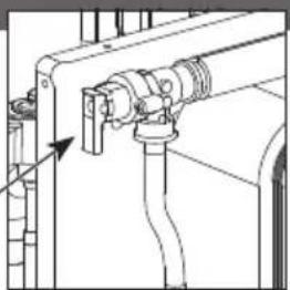
natural_image
Technical line drawing of a mechanical assembly with pipes and a valve (no text or symbols)Water fi Iter
- Clean the water filter at least once a year. Failure to do so may cause the filter to clog up, which may lead to system breakdown. Consult an authorised dealer/specialist.
- Please remove the magnet, after that please remove the accumulated dust inside.
* See section Maintenance in the AIR-TO-WATER HEATPUMP OUTDOOR UNIT Installation Manual.
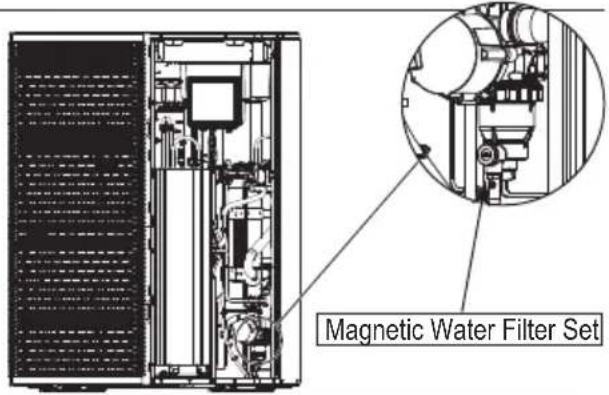
Indoor unit
- Do not splash water directly.
Wipe the unit gently with a soft dry cloth. - Please ensure the front plate is put back in place after servicing or maintenance.

natural_image
Simple line drawing of a rectangular industrial or storage unit with top and bottom ports, no text or symbols present.Safety relief valve
This Air-to-Water Hydromodule + Tank has one safety valves.
- The TANK's safety relief valve sometimes releases a little water after hot water usage. This is because the cold water, which enters the water heater, expands
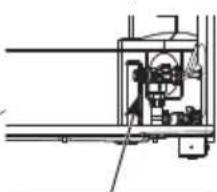
natural_image
Pure mechanical assembly diagram without any text, numbers, or symbolswhen heated, causing the pressure to rise and the safety valve to open.
safety relief valve
Tips: For extended non-use
Do not switch off the power supply.
Switching off the power supply will stop the automatic water pump operation and will occur water leakage or breakage of parts due to water freezing.
Info: Non serviceable criteria
Disconnect the power supply
then please consult an authorised dealer/specialist under the following conditions:
- Abnormal noise during operation.
• Water/foreign particles have entered the Remote Controller.
• Water leak from the indoor unit. - Circuit breaker switches off frequently.
- Power supply cable becomes excessively warm.
Maintenance
If the pressure is too low in the CIRCUIT system, it needs to be topped up. See the installation Manual for more information.
VENTING THE CIRCUIT SYSTEM
In the event of repeated filling of the CIRCUIT system, or if bubbling sounds are heard from the indoor module, the system may need venting. This is done as follows:
- Turn off the power supply to the indoor module.
- Vent the indoor module via the vent valves and the rest of the climate system via the relevant vent valves.
- Keep topping up and venting until all air has been removed and the pressure is correct.
The climate system may require topping up after venting.
In rare cases, flammable gas may be mixed in, so when venting, keep ignition sources away and ventilate well.
User
- In order to ensure optimal performance of units, user may inspect and clear any obstruction on the air inlet and outlet vents of the outdoor unit.
- User should not try to service or replace parts of the unit.
- Contact authorised dealer/specialist for scheduled inspection.
- Contact authorised dealer/specialist in case that the Network Adaptor is built in the indoor unit and therefore user cannot operate it.
Dealer/Specialist
- In order to ensure safety and optimal performance of the units, seasonal inspections on the units, functional check of RCCB/ELCB, field wiring and piping have to be carried out at regular intervals by authorised dealer/specialist.
- If the Water Filter Set installed specific to the Sanitary Water Tank, it is important to service the Water Filter Set periodically.
The following symptoms do not indicate malfunction.
| Symptom Cause | |
| Water flowing sound during operation. | • Refrigerant flow inside the unit. |
| Operation delayed for a few minutes after restarting. | • The delay is a protection for the compressor. |
| The outdoor unit emits water/steam. | • Condensation or evaporation occurring in the pipes. |
| Steam comes out of the outdoor unit in the heating mode. | • It is caused by defrost operation in the heat exchanger. |
| The outdoor unit does not operate. | • It is caused by the protection control of the system when outdoor temperature is out of the operating range. |
| The system operation switches off. | • It is caused by the protection control of the system. When the water inlet temperature is lower than 18 °C, the compressor stops and the backup heater power turns on. |
| The system is hard to heat up. | • When the panel and the floor are heated simultaneously, warm water temperature may decrease, which may reduce the heating ability of the system.• When the outdoor air temperature is low, the system may need longer time to heat up.• Discharge outlet or intake inlet in the outdoor unit is blocked by some obstacle, such as a pile of snow.• When the preset water outlet temperature is low, the system may need longer time to heat up. |
| The system does not heat up instantly. | • System will take some time to heat up the water if it starts to operate at cold water temperature. |
| Backup heater is automatically turned ON when it is disabled. | • It is caused by the protection control of the heat exchanger and water circuit. |
| Operation starts automatically even though the timer is not set. | • Sterilization timer has been set.• Anti-stick mode runs automatically at 3:00am every Monday. |
| Loud refrigerant noise continues for several minutes. | • It is caused by protection control during deice operation at outdoor ambient temperature lower than -10 °C. |
| *1,*2 COOL mode is unavailable. | • System has been locked to operate in HEAT mode only. |
Check the following before calling for servicing.
| Symptom Check | |
| Operation in HEAT/^*1, *2 COOL mode is not working efficiently. | Set the temperature correctly.Check the panel heater/cooler valve is opened.Clear any obstruction in the air inlet and air outlet vents of the outdoor unit. |
| Noisy during operation. | Outdoor unit or indoor unit has been installed at an incline.Close the cover properly. |
| System does not work. • Circuit breaker | has tripped/activated. |
| Operation LED is not lit or nothing is displayed on the Remote Controller. | Power supply is working correctly, or a power failure has occurred. |
*1 The system is locked to operate without COOL mode. It can be unlocked only by authorised installers or our authorised service partners.
*2 Only displayed when COOL mode is unlocked (This means when COOL mode is available).
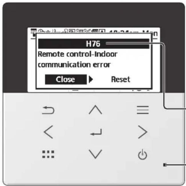
Below is a list of error codes that may appear on the display when there is some trouble with the system setting or operation.
When the display shows an error code as indicated below, contact the number registered in the Remote Controller or a nearest authorised installer.
All switches are disabled except < > and .
Error number
Blinking
Error No. Error explanation
| H12 Capacity mismatch | |
| H15 Compressor sensor error | |
| H17 Zone 2 pump error | |
| H20 Pump error | |
| H21 Water pressure error | |
| H22 Tank sensor 2 error | |
| H23 Refrigerant sensor error | |
| H27 Service valve error | |
| H28 Solar sensor error | |
| H31 Pool sensor error | |
| H36 Buffer tank sensor error | |
| H42 Low pressure protection | |
| H43 Zone 1 sensor error | |
| H44 Zone 2 sensor error | |
| H62 Water flow error | |
| H64 High pressure sensor error | |
| H65 Deice water circulation error | |
| H67 External thermistor 1 error | |
| H68 External thermistor 2 error | |
| H70 Back-up heater OLP error | |
| H72 Tank sensor 1 error | |
| H74 PCB communication error | |
| H75 Low water temp protection | |
| H76 | RC-1 & Indoor communication errorRC-1 & RC-2 communication error |
| H90 Indoor-Outdoor communication error | |
| H91 Tank heater OLP error | |
| H98 High pressure protection | |
| H99 Indoor freeze prevention | |
| Error No. | Error explanation |
| F12 | Pressure switch activated |
| F14 | Poor compressor rotation |
| F15 | Fan motor lock error |
| F16 | Current protection |
| F20 | Compressor overload protection |
| F22 | Transistor module overload protection |
| F23 | DC peak |
| F24 | Refrigerant cycle error |
| F25 * | ^1,*2 Cool / heat cycle error |
| F27 | Pressure switch error |
| F30 | Water outlet sensor 2 error |
| F32 | RC-1's internal thermostat errorRC-2's internal thermostat error |
| F35 | External meter communication error |
| F36 | Outdoor ambient sensor error |
| F37 | Water inlet sensor error |
| F40 | Outdoor discharge sensor error |
| F41 | Power factor correction error |
| F42 | Outdoor heat exchanger sensor error |
| F45 | Water outlet sensor error |
| F46 | Current transformer disconnection |
| F48 | Evaporator outlet sensor error |
| F49 | Bypass outlet sensor error |
| F50 | Water inlet 2 sensor error |
| F51 | Economizer outlet sensor error |
| F52 | Bypass inlet sensor error |
| F53 | Main expansion valve overcurrent protection |
| F54 | Bypass expansion valve overcurrent protection |
| F55 | Electrical anode error |
| F56 | Outdoor heat exchanger middle sensor error |
| F95 * | ^1,*2 Cooling high pressure error |
* Some error code may not be applicable to your model. Consult authorised dealer/specialist for clarification.
*1 The system is locked to operate without COOL mode. It can be unlocked only by authorised installers or our authorised service partners.
*2 Only displayed when COOL mode is unlocked (This means when COOL mode is available).
Information when connect to Network Adaptor (Accessories parts for Outdoorunit, Bundled Accessories parts for Panasonic AIR-TO-WATER HYDROMODULE + TANK)

WARNING
Before use, check the safety around the Air-to-Water system. Confirm human and living objects at surrounding before operation.
Incorrect operation due to failure to follow instructions may cause harm and damage.

Confir rm the below before operation (inside premises)
- Timer setting condition. Unpredictable on/off operation may cause serious injury or damage to human and living objects.
Confir rm the below before and during operation (outside from premises)
- If is known someone in the premises, notify the person from outside of new operation setting prior executing. This is to avoid sudden shock to the person and any serious health breakdown duly from operation changed.
- Please do not use this appliance when infant, physical disability person or elderly who unable to operate the appliance by themselves in the premises.
- Check the setting and operation status frequently.
- Stop the operation when error code is displayed and consult an authorised dealer or specialist.
Please confi rm before use
- The system may not usable when communication condition is bad. Please check "Operation Status" from the application display after operation. The following condition may happen in the remote operation.
- Cannot operate, operation time is not reflected.
- Air-to-Water operation is not reflected when operation is set outside of premises.
- It is recommended to lock screen the smart phone device to prevent miss-operation.
- Do not use other remote control, communication and operation device not specified by an authorised dealer or specialist.
- Use under the agreement of "Terms of Service" and "Handling of Personal Information" of Panasonic Smart Application.
- For extended non-use of Panasonic Smart Application, disconnect the network adaptor from the device.
Information for Users on Collection and Disposal of Old Equipment
Only for European Union and countries with recycling systems
These symbols on the products, packaging, and/or accompanying documents mean that used electrical and electronic products and batteries must not be mixed with general household waste.
For proper treatment, recovery and recycling of old products and used batteries, please take them to applicable collection points in accordance with your national legislation.
By disposing of them correctly, you will help to save valuable resources and prevent any potential negative effects on human health and the environment.
For more information about collection and recycling, please contact your local authority.
Penalties may be applicable for incorrect disposal of this waste, in accordance with national legislation.
For business users in the European Union and some other European countries
If you wish to discard electrical and electronic equipment, please contact your dealer or supplier for further information.
[Information on Disposal in other Countries outside the European Union]
These symbols are only valid in the European Union. If you wish to discard these items, please contact your local authority or dealer and ask for the correct method of disposal.
Symbols: Explanation of symbols that may be present in this manual.
 WARNING WARNING | This symbol shows that this equipment uses a fl ammable refrigerant with safety A3 group per ISO 817. If the refrigerant is leaked, together with an external ignition source, there is a possibility of fi re / explosion. |  | This symbol shows that the Operation Instructions should be read carefully. |
 | This symbol shows that a service personnel should be handling this equipment with reference to the Installation Instructions. |  | This symbol shows that there is information included in the Operation Instructions and/or Installation Instructions. |
| Country Hotline Phone Number | Country Hotline Phone Numb |
| Austria 0800 - 700666 Hungary +36 1 382 60 60 | |
| Baltic +46 8 680 26 50 Netherlands +31(0)736402538 | |
| Bulgaria +359 2 971 29 69 Norway +47 210 339 99 | |
| Croatia +36 1 382 60 60 Poland +48 22 29 53 727 | |
| Czech Republic +420 236 032 511 Spain | |
| Denmark | +45 369 277 99 |
| Finland | +358 923 195 432 |
| France +33(0) 892 183 184 | UK/Ireland |
| Germany | 0800 - 2002223 |
Manufactured by:
Panasonic Corporation
1006, Oaza Kadoma, Kadoma City,
Osaka 571-8501, Japan
Website: http://www.panasonic.com
© Panasonic Corporation 2024
| +34 (0) 902 153 060 | |
| Sweden | +46 (0)8 566 426 88 |
| Switzerland | 0800 - 001074 |
| +44 (0) 1344 853 393 |
Importer:
Panasonic Marketing Europe GmbH
Authorized Representative in EU:
Panasonic Testing Centre
Winsbergring 15, 22525 Hamburg, Germany
Contact in the UK:
Panasonic UK, a branch of Panasonic
Maxis 2, Western Road, Bracknell,
Berkshire, RG12 1RT
Panasonic®
natural_image
Line drawing of a rectangular book or shelf with vertical spine and front cover (no text or symbols)Модел №
Външно тяло
WH-WXG09ME8
WH-WXG12ME8
WH-WXG16ME8

natural_image
Line drawing of a rectangular industrial or electrical cabinet with multiple terminals and a window (no text or symbols)natural_image
Simple diagram showing a rectangular shape with a hatched fill and an internal rectangle, labeled 'A' at the bottom left (no text or symbols within the shape itself)A 1000 MM
A 2200 MM
B 2700 MM
C 300 MM
D 500 MM
E 1000 MM
F 500 MM
G 1800 MM
A 2200 MM
B 2700 MM
C 300 MM
D 500 MM
E 1000 MM
F 500 MM
G 1800 MM
natural_image
Illustration of a pointing hand with directional arrows (no text or symbols)
Без писалка

natural_image
Hand holding a pen writing on paper with an arrow and checkmark (no text or symbols present)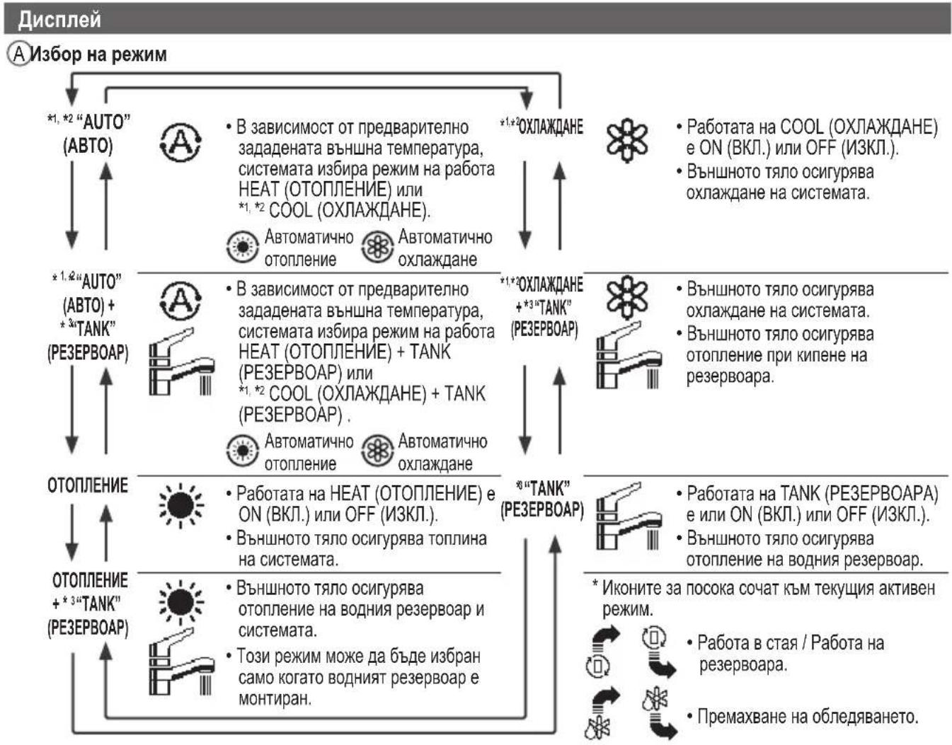
natural_image
Technical line drawing of a mechanical assembly with pipes and a valve (no text or symbols)Филтър за вода
natural_image
Simple line drawing of a rectangular industrial or laboratory container with three top ports and a circular base (no text or symbols)natural_image
Pure mechanical assembly diagram without any text, numbers, or symbols1006, Oaza Kadoma, Kadoma City,
© Panasonic Corporation 2024
| +34 (0) 902 153 060 | |
| Sweden | +46 (0)8 566 426 88 |
| Switzerland | 0800 - 001074 |
| +44 (0) 1344 853 393 |
Вносител:
Panasonic Marketing Europe GmbH
Panasonic Testing Centre
Winsbergring 15, 22525 Hamburg, Германия
Contact in the UK:
Panasonic UK, a branch of Panasonic
Maxis 2, Western Road, Bracknell,
Berkshire, RG12 1RT
Panasonic®
Návod k obsluze
natural_image
Line drawing of a rectangular box with four vertical panels and a central horizontal divider (no text or symbols)Model č.
Venkovní Jednotka
WH-WXG09ME8
WH-WXG12ME8
WH-WXG16ME8
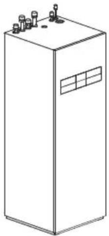
natural_image
Line drawing of a rectangular industrial or electrical cabinet with multiple terminals and a window (no text or symbols)natural_image
Simple diagram showing a shaded oval shape with an internal rectangle and label 'A' (no text or symbols beyond the label)A 1000 mm
A 2200 mm
B 2700 mm
C 300 mm
D 500 mm
E 1000 mm
F 500 mm
G 1800 mm
A 2200 mm
B 3200 mm
C 300 mm
D 1000 mm
A 2200 mm
B 2700 mm
C 300 mm
D 500 mm
E 1000 mm
F 500 mm
G 1800 mm
natural_image
Illustration of a pointing hand with directional arrows (no text or symbols)
Ne perem

natural_image
Hand holding a pen writing on paper (no text or symbols present)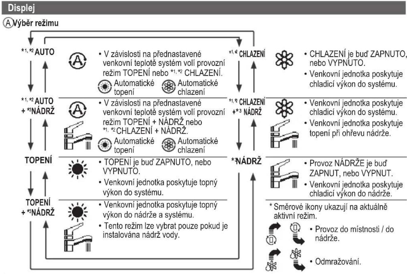
flowchart
graph TD
    A["Displej"] --> B["A Výběr režimu"]
    B --> C["*1,*2 AUTO"]
    C --> D["*1,*2 AUTO + *3 NÁDRŽ"]
    D --> E["TOPENÍ"]
    E --> F["TOPENÍ + *3 NÁDRŽ"]
    F --> G["*1,*2 CHLAZENÍ"]
    G --> H["*1,*2 CHLAZENÍ + *3 NÁDRŽ"]
    H --> I["*3 NÁDRŽ"]
    I --> J["*1,*2 CHLAZENÍ"]
    J --> K["*1,*2 CHLAZENÍ + *3 NÁDRŽ"]
    K --> L["*3 NÁDRŽ"]

    style A fill:#f9f,stroke:#333
    style B fill:#ccf,stroke:#333
    style C fill:#cfc,stroke:#333
    style D fill:#fcc,stroke:#333
    style E fill:#cff,stroke:#333
    style F fill:#ffc,stroke:#333
    style G fill:#fcf,stroke:#333
    style H fill:#cff,stroke:#333
    style I fill:#fcf,stroke:#333
    style J fill:#cff,stroke:#333
    style K fill:#fcf,stroke:#333
    style L fill:#cff,stroke:#333
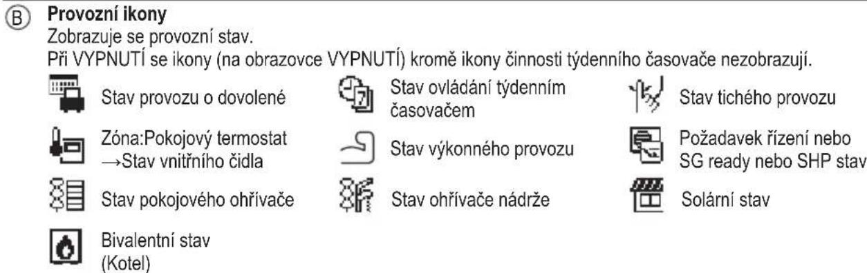
natural_image
Technical line drawing of a mechanical assembly with pipes and a valve (no text or symbols)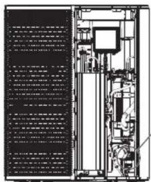
natural_image
Technical line drawing of an industrial machine or control unit with internal components and no visible text or symbols
natural_image
Simple line drawing of a rectangular industrial or electrical cabinet with top and bottom ports (no text or symbols)natural_image
Pure mechanical assembly diagram without any text, numbers, or symbols1006, Oaza Kadoma, Kadoma City,
© Panasonic Corporation 2024
| Sweden | +46 (0)8 566 426 88 |
| Switzerland | 0800 - 001074 |
| +44 (0) 1344 853 393 |
Dovozce:
Panasonic Marketing Europe GmbH
Panasonic Testing Centre
Panasonic UK, a branch of Panasonic
Maxis 2, Western Road, Bracknell,
Berkshire, RG12 1RT
Panasonic®
natural_image
Line drawing of a rectangular book or shelf with vertical spine and front cover (no text or symbols)Model nr.
Udendørs Enhed
WH-WXG09ME8
WH-WXG12ME8
WH-WXG16ME8

natural_image
Line drawing of a rectangular industrial or electrical cabinet with multiple terminals and a window (no text or symbols)natural_image
Simple diagram showing a shaded oval shape with an internal rectangle and label 'A' (no text or symbols beyond the label)A 1000 mm
A 2200 mm
B 2700 mm
C 300 mm
D 500 mm
E 1000 mm
F 500 mm
G 1800 mm
A 2200 mm
B 2700 mm
C 300 mm
D 500 mm
E 1000 mm
F 500 mm
G 1800 mm
natural_image
Illustration of a pointing hand with directional arrows (no text or symbols)Enter-knap
natural_image
Hand holding a pen writing on paper with an arrow pointing downward (no text or symbols present)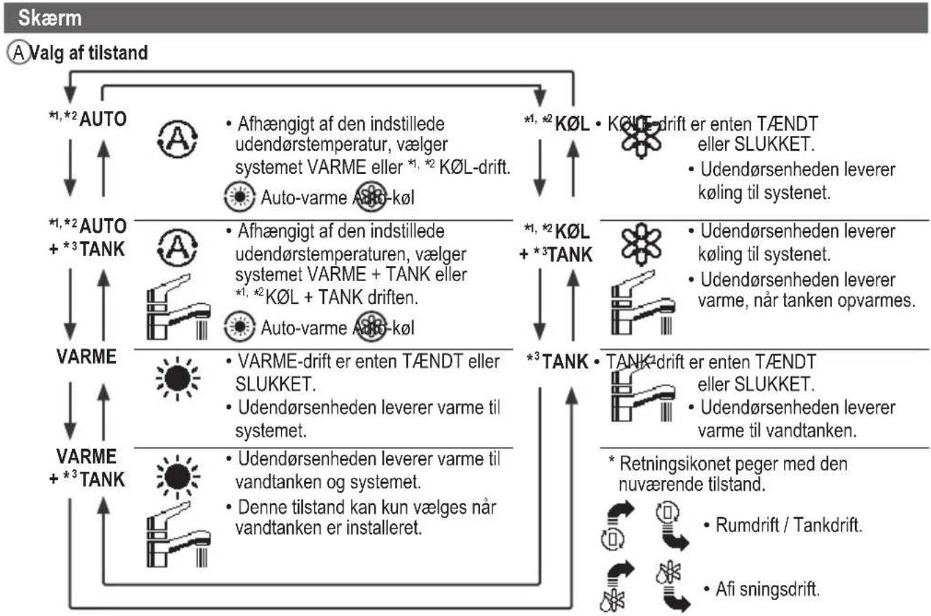
©Temperatur for hver zone
DTid og dag
E Vandbeholdertemperatur (med ikon for elektrisk anodedrift)
F Udendørstemperatur
© Sensortype/Indstil temperaturtypens ikoner


Vandtemperatur →Kompenseringskurve
Rumtermostat → Ekstern


natural_image
Simple line drawing of a rectangular industrial or electrical cabinet with three top ports and a circular base (no text or symbols)Overtryksventil
Forhandler/Specialist
© Panasonic Corporation 2024
| +34 (0) 902 153 060 | |
| Sweden | +46 (0)8 566 426 88 |
| Switzerland | 0800 - 001074 |
| +44 (0) 1344 853 393 |
Importør:
Panasonic Marketing Europe GmbH
Panasonic Testing Centre
Winsbergring 15, 22525 Hamburg, Tyskland
Contact in the UK:
Panasonic UK, a branch of Panasonic
Maxis 2, Western Road, Bracknell,
Berkshire, RG12 1RT
Panasonic®
Bedienungsanleitung
natural_image
Line drawing of a rectangular box with four vertical panels and a central horizontal divider (no text or symbols)Modell-Nr.
Außengerät
WH-WXG09ME8
WH-WXG12ME8
WH-WXG16ME8

natural_image
Line drawing of a rectangular industrial or electrical cabinet with multiple terminals and a window (no text or symbols)natural_image
Simple diagram showing a rectangular object inside a rounded rectangle with a diagonal hatching, labeled 'A' at the center (no text or symbols within the shape)A 1000 mm
A 2200 mm
B 2700 mm
C 300 mm
D 500 mm
E 1000 mm
F 500 mm
G 1800 mm
A 2200 mm
B 2700 mm
C 300 mm
D 500 mm
E 1000 mm
F 500 mm
G 1800 mm
natural_image
Illustration of a pointing hand with directional arrows (no text or symbols)
Kein Stift
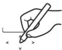
natural_image
Hand holding a pen writing on paper with an arrow and 'v' mark (no text or symbols on the pen itself)
Kreuztasten
Raumthermostat →Extern

natural_image
Technical line drawing of a mechanical assembly with pipes and a valve (no text or symbols)Wasserfi Iter
natural_image
Simple line drawing of a rectangular industrial or electrical cabinet with top and bottom terminals (no text or symbols)Sicherheitsventil
natural_image
Pure mechanical assembly diagram without any text, numbers, or symbolsSicherheitsventil
1006, Oaza Kadoma, Kadoma City,
Osaka 571-8501, Japan
Website: http://www.panasonic.com
© Panasonic Corporation 2024
| Sweden | +46 (0)8 566 426 88 |
| Switzerland | 0800 - 001074 |
| +44 (0) 1344 853 393 |
Importeur:
Panasonic Marketing Europe GmbH
Panasonic Testing Centre
Winsbergring 15, 22525 Hamburg,
Deutschland
Contact in the UK:
Panasonic UK, a branch of Panasonic
Maxis 2, Western Road, Bracknell,
Berkshire, RG12 1RT
Panasonic®
Οδηγίες λειτουργίας
natural_image
Line drawing of a rectangular box with vertical panels and horizontal connectors (no text or symbols)Αρ. μοντέλου
Εξωτερική Μονάδα
WH-WXG09ME8
WH-WXG12ME8
WH-WXG16ME8

natural_image
Line drawing of a rectangular industrial or electrical cabinet with multiple terminals and a window (no text or symbols)natural_image
Simple diagram showing a rectangular shape with a shaded inner region and an arrow labeled 'A' pointing to it (no text or symbols beyond the label)A 1000 mm
natural_image
Pure technical diagram of a mechanical component with no text, numbers, or symbolsA 2200 mm
B 2700 mm
C 300 mm
D 500 mm
E 1000 mm
F 500 mm
G 1800 mm
natural_image
Illustration of a pointing hand with directional arrows (no text or symbols)
Χωρίς στυλό
natural_image
Hand holding a pen writing on paper with eraser and pencil (no text or symbols)Οθόνη
The Ground Truth image displays a single, solid horizontal line. According to Rule 2 (UNDERSCORE & LINE RULES), this is a stylistic or background line, not a placeholder underscore. Therefore, the OCR result must ignore it and output nothing or only meaningful text. The provided OCR content is "____", which consists of four underscores. This is an incorrect interpretation of the line as a placeholder, violating the rule that stylistic lines must be ignored. The OCR has hallucinated underscores where none should exist based on the GT's visual context. Hence, the OCR result is inconsistent with the Ground Truth.
natural_image
Technical line drawing of a mechanical assembly with pipes and a valve (no text or symbols)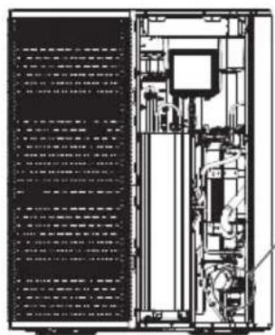
natural_image
Technical line drawing of a server rack with internal components and ventilation ducts (no text or labels)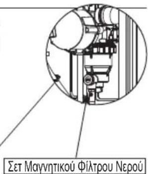
natural_image
Simple line drawing of a rectangular industrial or laboratory container with three top ports and a circular base (no text or symbols)natural_image
Pure mechanical assembly diagram without any text, numbers, or symbols© Panasonic Corporation 2024
| +34 (0) 902 153 060 | |
| Sweden | +46 (0)8 566 426 88 |
| Switzerland | 0800 - 001074 |
| +44 (0) 1344 853 393 |
Εισαγωγέας:
Panasonic Marketing Europe GmbH
Panasonic Testing Centre
Panasonic UK, a branch of Panasonic
Maxis 2, Western Road, Bracknell,
Berkshire, RG12 1RT
Panasonic®
natural_image
Line drawing of a rectangular book or shelf with visible spine and front cover (no text or symbols)N°. de modelo
Unidad exterior
WH-WXG09ME8
WH-WXG12ME8
WH-WXG16ME8

natural_image
Line drawing of a rectangular industrial or storage unit with multiple ports and a window (no text or symbols)5.9 Res. band. condens.
5.10 Sensor exterior alternativo
natural_image
Simple diagram showing a rectangular shape with a shaded inner region and an arrow labeled 'A' pointing to its center (no text or symbols beyond the label)A 1000 mm
A 2200 mm
B 2700 mm
C 300 mm
D 500 mm
E 1000 mm
F 500 mm
G 1800 mm
A 2200 mm
B 2700 mm
C 300 mm
D 500 mm
E 1000 mm
F 500 mm
G 1800 mm
natural_image
Illustration of a pointing hand with directional arrows (no text or symbols)
No use bolígrafos.
natural_image
Hand holding a pen writing on paper with an arrow and checkmark (no text or symbols present)Pantalla
natural_image
Technical line drawing of a mechanical assembly with pipes and a valve (no text or symbols)Filtro
natural_image
Simple line drawing of a rectangular industrial or electrical cabinet with three top ports and a circular base (no text or symbols)natural_image
Pure mechanical assembly diagram without any text, numbers, or symbols© Panasonic Corporation 2024
| +34 (0) 902 153 060 | |
| Sweden | +46 (0)8 566 426 88 |
| Switzerland | 0800 - 001074 |
| +44 (0) 1344 853 393 |
Importador:
Panasonic Marketing Europe GmbH
Panasonic Testing Centre
Panasonic UK, a branch of Panasonic
Maxis 2, Western Road, Bracknell,
Berkshire, RG12 1RT
Panasonic®
Kasutusjuhend
natural_image
Line drawing of a rectangular book or shelf with vertical spine and front cover (no text or symbols)Mudeli nr
Väline seade
WH-WXG09ME8
WH-WXG12ME8
WH-WXG16ME8

natural_image
Line drawing of a rectangular industrial or electrical cabinet with multiple terminals and a window (no text or symbols)Kohaldatav siseruumi
seade
Hüdromoodul + paak
WH-ADC0316M9E82
WH-ADC0316M9E8AN2
EESTI
natural_image
Simple diagram showing a rectangular shape with a shaded inner region and an arrow labeled 'A' pointing to its center (no text or symbols beyond the label)A 1000 mm
2) Kaitsetsoon maapinnale paigaldamisel hoone seina ette
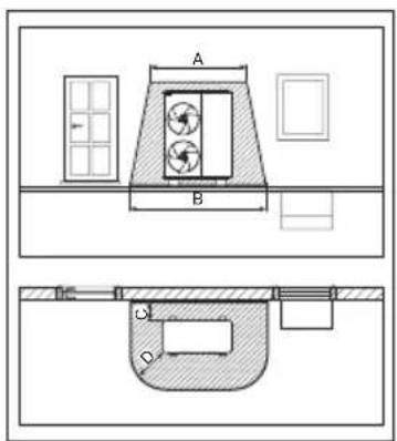
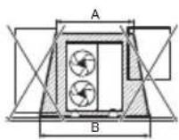
A 2200 mm
B 3200 mm
C 300 mm
D 1000 mm
3) Kaitsetsoon maapinnale paigaldamisel hoone nurka
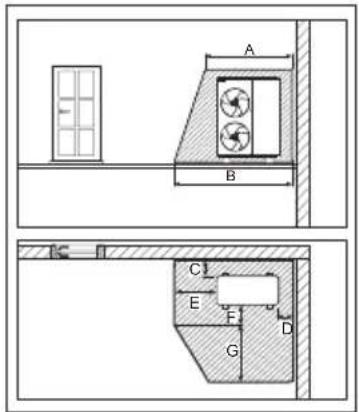
A 2200 mm
B 2700 mm
C 300 mm
D 500 mm
E 1000 mm
F 500 mm
G 1800 mm
4) Kaitsetsoon seinale paigaldamisel hoone seina ette
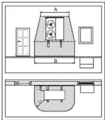
A 2200 mm
B 3200 mm
C 300 mm
D 1000 mm
Kaitsetsoon toote all ulatub maapinnani.
5) Kaitsetsoon seinale paigaldamisel hoone nurka
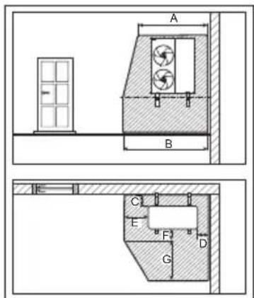
A 2200 mm
B 2700 mm
C 300 mm
D 500 mm
E 1000 mm
F 500 mm
G 1800 mm
Kaitsetsoon toote all ulatub maapinnani.
natural_image
Illustration of a pointing hand with directional arrows (no text or symbols)
Mitte pliiatsiga

natural_image
Hand holding a pen writing on paper with an arrow and checkmark (no text or symbols present)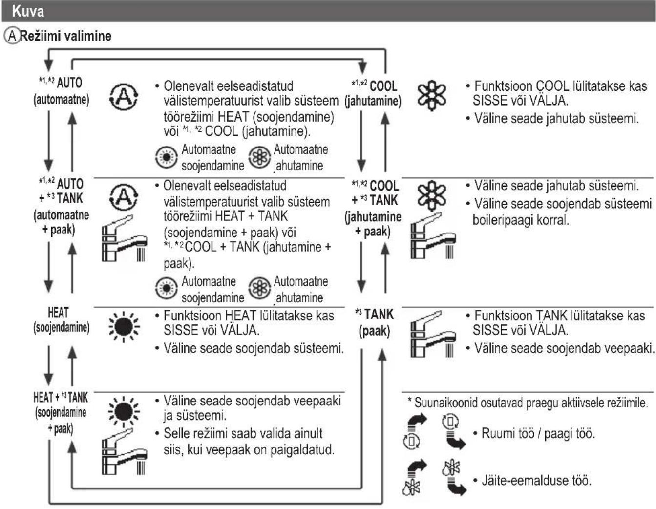
- Operating Instructions
- ENGLISH
- Table of contents
- For user
- For installer
- Before use, make sure the system has been installed correctly by an authorised dealer/specialist according to the given instructions.
- System overview
- Operating conditions
- WARNING
- CAUTION
- Indoor unit and outdoor unit
- Power supply
- Remote Controller
- Precaution for using R290 refrigerant
- Installation (Space)
- Servicing
- 2-1. Service personnel
- 2-2. Work
- 2-3. Checking for presence of refrigerant
- 2-4. Presence of fi re extinguisher
- 2-5. No ignition sources
- 2-6. Ventilated area
- 2-7. Checks to the refrigerating equipment
- 2-8. Checks to electrical devices
- Repairs to sealed components
- Repairs to intrinsically safe components
- Cabling
- Detection of fl ammable refrigerants
- The following leak detection methods are deemed acceptable for all refrigerant systems
- Removal and evacuation
- Charging procedures
- Decommissioning
- Labelling
- Recovery
- Remote Controller buttons and display
- Buttons / Indicator
- Selecting the language
- Setting the clock
- Checking the front grilles
- Force DHW
- Note:
- Powerful
- Quiet
- Force Heater
- Weekly Timer
- Select "Yes".
- [Example of a Timer setup]
- Force Defrost
- Error Reset
- R/C Lock
- To unlock the Remote Controller
- To reset forgotten password (under operation OFF screen)
- Menu Default Setting Setting Options / Display
- Function setup
- > Weekly timer
- Timer setup
- Timer copy
- > Holiday timer
- >ON
- >Quiet timer
- Installer setup System setup
- > \*1 Optional PCB connectivity
- > Zone & Sensor
- > \*1 Heater capacity
- > Anti freezing
- > \*2 Tank connection
- Price (Pattern 1/2/3/4) : 1
- Cleaning instructions
- Regular Checks
- Water pressure check
- Outdoor unit
- Water fi Iter
- Indoor unit
- Safety relief valve
- Tips: For extended non-use
- Info: Non serviceable criteria
- Disconnect the power supply
- Maintenance
- VENTING THE CIRCUIT SYSTEM
- User
- Dealer/Specialist
- Please confi rm before use
- Information for Users on Collection and Disposal of Old Equipment
- Panasonic®
- Филтър за вода
- Návod k obsluze
- ©Temperatur for hver zone
- DTid og dag
- E Vandbeholdertemperatur (med ikon for elektrisk anodedrift)
- F Udendørstemperatur
- © Sensortype/Indstil temperaturtypens ikoner
- Overtryksventil
- Forhandler/Specialist
- Bedienungsanleitung
- Wasserfi Iter
- Sicherheitsventil
- Οδηγίες λειτουργίας
- Οθόνη
- Pantalla
- Filtro
- Kasutusjuhend
- EESTI
Brand : PANASONIC
Model : WH-WXG16ME8
Category : Air Conditioning