FM07IDU32 - Air Conditioning WHIRLPOOL - Free user manual and instructions
Find the device manual for free FM07IDU32 WHIRLPOOL in PDF.

| Brand | Whirlpool |
| Model | FM07IDU32 |
| Category | Split air conditioner |
| Type | Inverter Plus |
| Functions | Cooling, Heating, Dehumidification, Ventilation |
| Cooling capacity | 20 000 BTU/h |
| Heating capacity | 20 000 BTU/h |
| Refrigerant | R32 |
| Refrigerant weight | 1.45 kg |
| Power supply | 230 V ~ 50 Hz |
| Indoor unit dimensions (WxHxD) | Approx. 800 x 300 x 200 mm |
| Outdoor unit dimensions (WxHxD) | Approx. 800 x 600 x 300 mm |
| Indoor unit weight | Approx. 10 kg |
| Outdoor unit weight | Approx. 30 kg |
| Max pipe length | 20 m |
| Max height difference | 10 m |
| Air filter | Washable, clean every 720 hours |
| Special functions | Jet, Sleep (4 modes), Round U, Power Save, Super Silent |
| Maintenance and cleaning | Clean the filter regularly, wipe the front panel with a soft cloth |
| Safety | Anti-freeze protection, automatic defrost, automatic shutdown in case of malfunction |
| General information | Manual provided, Whirlpool technical support |
Frequently Asked Questions - FM07IDU32 WHIRLPOOL
User questions about FM07IDU32 WHIRLPOOL
0 question about this device. Answer the ones you know or ask your own.
Ask a new question about this device
Download the instructions for your Air Conditioning in PDF format for free! Find your manual FM07IDU32 - WHIRLPOOL and take your electronic device back in hand. On this page are published all the documents necessary for the use of your device. FM07IDU32 by WHIRLPOOL.
USER MANUAL FM07IDU32 WHIRLPOOL
Instructions for use
Mode d'emploi
Gebruiksaanwijzing
natural_image
Close-up of three wooden clothespins with metal fittings and screws, arranged diagonally (no text or symbols visible)Brugsanvisning
Bruksanvisning
Käyttöohje
natural_image
Black and white photo of three empty glass bottles with black lids, no visible text or symbols
natural_image
Black and white close-up of multiple glasses with blurred background (no text or symbols)Οδηγίες χρήσης
natural_image
Close-up of a metallic kitchen appliance with perforated door and side panel (no visible text or symbols)Návod k použití
Návod na použitie
Vorsichtsmaßnahmen
natural_image
Line drawing of hands installing or adjusting a component on a wall, with no text or symbols present.SLEEP 1→SLEEP 2→SLEEP 3→SLEEP 4→NORMAL
natural_image
Diagram of a cylindrical air conditioner with airflow arrows indicating direction (no text or symbols)Abb. A

natural_image
Technical line drawing of a mechanical component with a meshed panel and an arrow indicating direction (no text or symbols)
natural_image
Line drawing of a door panel with a black arrow pointing to the door handle (no text or symbols present)Abb. B

natural_image
Diagram of a car air conditioner unit with hand pressing down on the panel (no text or symbols)Abb. C

natural_image
Illustration of two hands holding a grid-patterned sheet with a tool, no text or symbols presentAbb. D
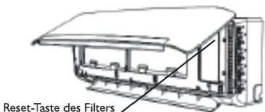
Abb. E
FEHLERSUCHE
natural_image
Illustration of hands using a tool to lift a blade, no text or symbols presentnatural_image
Technical line drawing of an air conditioning unit with cooling fan and internal wiring (no text or symbols)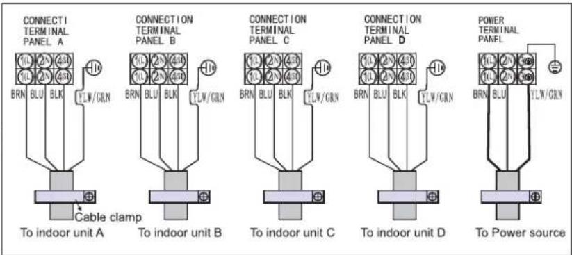
VORSICHT:
Please ready all instructions carefully before using this product. When using this appliances, should always follow this instruction to reduce the risk of fire, electric shock, and in jury to person.
Please keep this manual. If you deliver the appliance to other users, do handover this manual together.
These instructions shall also be available on website: www.whirlpool.eu.
SAFETY PRECAUTIONS
- The Installation and service/repair must be performed by a qualified technician, in compliance with the producer's instructions and following local safety norms. Do not repair or replace any parts of the appliance unless it is specifically written in the user instructions.
- Do not pull the power supply cord to remove it from the socket. Do not twist or press the power supply cord, and make sure it is not broken.
- Do not touch the power plug, circuit breaker and emergency button when your hands are wet.
- Do not insert your fingers or foreign substances into the air inlet/outlet of indoor&outdoor unit.
- Never block the air inlet or outlet of indoor and outdoor unit.
• Physically or mentally disabled people, children and people without any experience with the product are only allowed to use
the appliance if they have had specific training on how to operate the appliance by a person responsible for their security and well-being. The appliance is not intended for use by disabled without supervision.
- Children should be supervised to ensure that they do not play with the appliance (including remote control I).
- This appliance can be used by children aged from 8 years and above and persons with reduced physical, sensory or mental capabilities or lack of experience and knowledge if they have been given supervision or instruction concerning use of the appliance in a safe way and understand the hazards involved. Children shall not play with the appliance.
Cleaning and user maintenance shall not be made by children without supervision.
AIR CONDITIONER PRECAUTIONS
Please strictly follow the below instructions:
- Long and direct exposure to cool air might be harmful to health. It is advisable to set the louvers in order to avoid direct cool air and deflect it within the room.
- Upon malfunctioning first turn the appliance off by pressing the ON/OFF button on the remote control, then disconnect it from power supply.
• Always turn off the air conditioner by remote control first. Do not use the power supply circuit breaker or pull off the plug to turn it off.
- Do not switch the appliance on and off too often as this can damage the appliance.
- Maintenance and repair requiring the assistance of other skilled personnel shall be carried out under the supervision of the person competent in the use of flammable refrigerants.
- Do not place any objects on the outdoor unit.
- Disconnect the air conditioner from the power supply if it is to be left unused for a long period of time or during a thunder/lightning storm.
- This product contains Fluorinated Greenhouse Gases covered by the Kyoto Protocol, the refrigerant gas being in a hermetically sealed system. (R32 675/P)
| Model | 20K | 24K | 36K |
| Gas weight (kg) | 1.45 | 1.45 2. | 2 |
| CO2 equivalent(Ton) | 0.979 | 0.979 1. | 485 |
SAFETY INSTRUCTIONS FOR SERVICING APPLIANCE WITH SPESIFIC REFRIGERANT
- Download the complete manual for detailed installation, servicing, maintenance and repairing methods on docs.whirlpool.eu.
- Do not use means to accelerate the defrosting process or to clean, other than those recommended by the manufacturer.
- The appliance shall be stored in a well-ventilated area where the room size corresponds to the room area as specified for operation; without continuously operating ignition sources (such as; open flames, an operating gas appliance or an operating electric heater).
- Do not pierce or burn. Be aware that the refrigerants may not contain an odor.
- Any person who is involved with working on or breaking into a refrigerant circuit should hold a current valid certificate from an industry-accredited assessment authority, which authorizes their competence to handle refrigerants safely in accordance with an industry recognized assessment specification. Servicing shall only be performed as recommended by the equipment manufacturer. Maintenance and repair requiring the assistance of other skilled personnel shall be carried out under the supervision of the person competent in the use of flammable refrigerants. Appliance shall be installed, operated and stored in a room with a floor area larger than 10 m2. The installation of pipe-work shall be kept to a room with a floor area larger than 10 m2. The pipe-work shall be compliance with national gas regulations. The maximum refrigerant
charge amount is 2.5 kg. Mechanical connectors used indoors shall comply with ISO 14903. When mechanical connectors are reused indoors, sealing parts shall be renewed. When flared joints are reused indoors, the flare part shall be re fabricated. The installation of pipe-work shall be kept to a minimum. Mechanical connections shall be accessible for maintenance purposes.
- Transport of equipment containing flammable refrigerants shall be compliant with the transport regulations.
- Marking of equipment using signs shall be compliant with local regulations.
- Disposal of equipment using flammable refrigerants shall be compliant with national regulations.
- The storage of equipment / appliances should be in accordance with the manufacturer's instructions.
- Storage of packed (unsold) equipment Storage package protection should be constructed such that mechanical damage to the equipment inside the package will not cause a leak of the refrigerant charge. The maximum number of pieces of equipment permitted to be stored together will be by local regulations.
- Information on servicing.
6-1 Checks to the area
Prior to beginning work on system containing flammable refrigerants, safety checks are necessary to ensure that the risk of ignition is minimized. For repair to the refrigerating system the following precautions shall be complied with
prior to conducting work on the system.
6-2 Work procedure
Work shall be undertaken under a controlled procedure so as to minimize the risk of flammable gas or vapour being present while the work is being performed.
6-3 General work area
All maintenance staff and others working in the local area shall be instructed on the nature of work being carried out. Work in confied spaces shall be avoided. The area around the workspace shall be sectioned off. Ensure that the conditions within the area have been made safe by control of flammable material.
6-4 Checking for presence of refrigerant
The area shall be checked with an appropriate refrigerant detector prior to and during work, to ensure the technician is aware of prentially flammable atmospheres. Ensure that hte leak detection equipment being used is suitable for use with flammable refrigerants, i.e. non-sparking adequately sealed or intrinsically safe.
6-5 Presence of fire extinguisher If any hot work is to be conducted on the refrigeration equipment or any associated parts appropriate fire extinguishing equipment shall be available to hand. Have a dry powder or CO_2 fire extinguisher adjacent to the charging area.
6-6 No ignition sources
No person carrying out work in relation to a refrigeration system which involves exposing any pipe work that contains or has contained flammable refrigerant shall use any sources of ignition in such a manner that it may lead to the risk of fire or explosion. All possible ignition sources,
including cigarette smoking, should be kept sufficiently far away from the site of installation, repairing, removing and disposal, during which flammable refrigerant can possibly be released to the surrounding space. Prior to work taking place, the area around the equipment is to be surveyed to make sure that there are no flammable hazards or ignition risks. “No Smoking” signs shall be displayed.
6-7 Ventilated area
Ensure that the area is in the open or that it is adequately ventilated before breaking into the system or conducting any hot work. A degree of ventilation shall continue during the period that the work is carried out. The ventilation should safely disperse any released refrigerant and preferably expel it externally into the atmosphere.
6-8 Checks to the refrigeration equipment
Where electrical components are being changed, they shall be fit for the purpose and to the correct specification. At all times the manufacturer's maintenance and service guidelines shall be followed. If in doubt consult the manufacturer's technical department for assistance. The following checks shall be applied to installations using flammable refrigerants:
- The charge size is in accordance with the room size within which the refrigerant containing parts are installed;
- The ventilation machinery and outlets are operating adequately and are not obstructed;
- If an indirect refrigerating circuit is being used, the secondary circuit shall be checked for the presence of refrigerant;
- Marking to the equipment continues to be visible and legible. Markings and signs that are illegible shall be corrected; - Refrigeration pipe or components are installed in a position where they are unlikely to be exposed to any substance which may corrode refrigerant containing components, unless the components are constructed of materials which are inherently resistant to being corroded or are suitably protected against being so corroded.
6-9 Checks to electrical devices Repair and maintenance to electrical components shall include initial safety checks and component inspection procedures. If a fault exists that could compromise safety, then no electrical supply shall be connected to the circuit until it is satisfactory dealt with. if the fault cannot be corrected immediately but it is necessary to continue operation, an adequate temporary solution shall be used. This shall be reported to the owner of the equipment so all parts are advised. Initial safety checks shall include:
- That capacitors are discharged: this shall be done in a safe manner to avoid possibility of sparking; - That there no live electrical components and wiring are exposed while charging, recovering or purging the system; - That there is continuity of earth bonding.
- Repairs to sealed components During repairs to sealed components, all electrical supplies shall be disconnected from the equipment being worked upon prior to any removal of sealed electrical supply to equipment during servicing, then a permanently operating form of
leak detection shall be located at the most critical point to warn of a potentially hazardous situation. Particular attention shall be paid to the following to ensure that by working on coelectrical components. The casing is not altered in such a way that the level of protection is affected. This shall include damage to cables, excessive number of connections, terminals not made to original specification, damage to seals, incorrect fitting of glands, etc. Ensure that apparatus is mounted securely. Ensure that seals or sealing materials have not degraded such that they no longer serve the purpose of preventing the ingress of flammable atmospheres. Replacement parts shall be in accordance with the manufacturer's specifications.
NOTE:
The use of silicon sealant may inhibit the effectiveness of some types of leak detection equipment. Intrinsically safe components do not have to be isolated prior to working on them.
8. Repair to intrinsically safe components
Do not apply any permanent inductive or capacitance loads to the circuit without ensuring that this will not exceed the permissible voltage and current permitted for the equipment in use. Intrinsically safe components are the only types that can be worked on while live in the presence of a flammable atmosphere. The test apparatus shall be at the correct rating. Replace components only with parts specified by the manufacturer. Other parts may result in the ignition of refrigerant atmosphere from a leak.
9. Cabling
Check that cabling will not be subject to wear, corrosion, excessive pressure, vibration, sharp edges or any other
adverse environmental effects. The check shall also take into account the effects of aging or continual vibration from sources such as compressors or fans.
-
Detection of flammable refrigerants Under no circumstances shall potential sources of ignition be used in the searching for or detection of refrigerant leaks. A halide torch (or any other detector using a naked flame) shall not be used.
-
Leak detection methods The following leak detection methods are deemed acceptable for systems containing flammable refrigerants:
- Electronic leak detectors shall be used to detect flammable refrigerants, but the sensitivity may not be adequate, or may need re-calibration (Detection equipment shall be calibrated in a refrigerant-free area.)
- Ensure that the detector is not a potential source of ignition and is suitable for the refrigerant used.
- Leak detection equipment shall be set at a percentage of the LFL of the refrigerant and shall be calibrated to the refrigerant employed and the appropriate percentage of gas (25% maximum) is confirmed.
- Leak detection fluids are suitable for use with most refrigerants but the use of detergents containing chlorine shall be avoided as the chlorine may react with the refrigerant and corrode the copper pipe-work.
- If a leak is suspected, all naked flames shall be removed/ extinguished.
- If a leakage of refrigerant is found which requires brazing, all of the refrigerant shall be recovered from the system, or isolated (by means of shut off valves) in a part of the system remote from the leak.
- Oxygen free nitrogen (OFN) shall then be purged through the system
both before and during the brazing process.
- Removal and evacuation
- When breaking into the refrigerant circuit to make repairs - or for any other purpose conventional procedures shall be used. However, it is important that best practice is followed since flammability is a consideration.
The following procedure shall be adhered to:
- Remove refrigerant;
- Purge the circuit with inert gas;
- Evacuate;
- Purge again with inert gas;
- Open the circuit by cutting or brazing.
The refrigerant charge shall be recovered into the correct recovery cylinders. The system shall be “flushed” with OFN to render the unit safe. This process may need to be repeated several times. Compressed air or oxygen shall not be used for this task. Flushing shall be achieved by breaking to fill until the working pressure is achieved, then venting to atmosphere, and finally pulling down to a vacuum. This process shall be repeated until no refrigerant is within the system. When the final charge is used, the system shall be vented down to atmospheric pressure to enable work. This operation is absolutely vital if brazing operations, on the pipe-work are to take place. Ensure that the outlet for the vacuum pump is not close to any ignition sources and there is the vacuum in the system with OFN and continuing ventilation available.
- Charging procedures In addition to conventional charging procedures, the following requirements shall be followed:
- Ensure that contamination of different refrigerants does not occur when using charging equipment.
- Hoses or lines shall be as short as possible to minimize the amount of refrigerant contained in them.
- Cylinders shall be kept upright.
- Ensure that the refrigeration system is earthed prior to charging the system with refrigerant.
- Label the system when charging is complete (if not already).
- Extreme care shall be taken not to overfill the refrigeration system. Prior to recharging the system it shall be pressure tested with OFN.
The system shall be leak tested on completion of charging but prior to commissioning.
A follow up leak test shall be carried out prior to leaving the site.
- Decommissioning
Before carrying out this procedure, it is essential that the technician is completely familiar with the equipment and all its detail. It is recommended good practice that all refrigerants are recovered safely. Prior to the task being carried out, an oil and refrigerant sample shall be taken in case analysis is required prior to re-use of reclaimed refrigerant. It is essential that electrical power is available before the task is commenced.
a. Become familiar with the equipment and its operation.
b. Isolate system electrically.
c. Before attempting the procedure ensure that:
- Mechanical handling equipment is available, if required, for handling refrigerant cylinders;
- All personal protective equipment is available and being used correctly;
- The recovery process is supervised at all times by a competent person;
- Recovery equipment and cylinders conform to the appropriate standards.
d. Pump down refrigerant system, if possible.
e. If a vacuum is not possible, make a manifold so that refrigerant can be removed from various parts of the system.
f. Make sure that cylinder is situated on the scales before recovery takes place.
g. Start the recovery machine and operate in accordance with manufacturer's instructions.
h. Do not overfill cylinders. (No more than 80 % volume liquid charge).
i. Do not exceed the maximum working pressure of the cylinder, even temporarily.
j. When the cylinders have been filled correctly and the process completed, make sure that the cylinders and the equipment are removed from site promptly and all isolation valves on the equipment are closed off.
k. Recovered refrigerant shall not be charged into another refrigeration system unless it has been cleaned and checked.
- Labelling
Equipment shall be labelled stating that it has been de-commissioned and emptied of refrigerant. The label shall be dated and signed. Ensure that there are labels on the equipment stating the equipment contains flammable refrigerant.
16.Recovery
When removing refrigerant from a system, either for servicing or decommissioning, it is recommended good practice that all refrigerants are removed safely. When transferring refrigerant into cylinders, ensure that only appropriate refrigerant recovery cylinders are employed. Ensure that the correct number of cylinders for holding the total system charge is available. All cylinders to be used are designated for the recovered refrigerant and labelled for that refrigerant (i.e. special cylinders
for the recovery of refrigerant). Cylinders shall be complete with pressure relief valve and associated shutoff valves in good working order. Empty recovery cylinders are evacuated and, if possible, cooled before recovery occurs. The recovery equipment shall be in good working order with a set of instructions concerning the equipment that is at hand and shall be suitable for the recovery of flammable refrigerants. In addition, a set of calibrated weighing scales shall be available and in good working order. Hoses shall be complete with leak-free disconnect couplings and in good condition. Before using the recovery machine, check that it is in satisfactory working order, has been properly maintained and that any associated electrical components are sealed to prevent ignition in the event of a refrigerant release. Consult manufacturer if in doubt. The recovered refrigerant shall be returned to the refrigerant supplier in the correct recovery cylinder, and the relevant Waste Transfer Note arranged. Do not mix refrigerants in recovery units and especially not in cylinders. If compressors or compressor oils are to be removed, ensure that they have been evacuated to an acceptable level to make certain that flammable refrigerant does not remain within the lubricant. The evacuation process shall be carried out prior to returning the compressor to the suppliers. Only electric heating to the compressor body shall be employed to accelerate this process. When oil is drained from a system, it shall be carried out safely. When moving or relocating the air conditioner, consult experienced service technicians for disconnection and reinstallation of the unit. Do not place any other electrical products or household belongings under indoor unit or outdoor unit. Condensation dripping from the unit might get them wet, and may cause damage or malfunction of your property. To keep ventilation openings clear of obstruction. The appliance shall be stored in a well-ventilated area where the room size corresponds to the room area as specified for operation. The appliance shall be stored in a room without continuously operating open flames (for example an operating gas appliance) and ignition sources (for example an operating electric heater). Reusable mechanical connectors and flared joints are not allowed.
SAFE G RAID NG THE ENVIRONMENT
- This appliance has been made of recyclable or re-usable material. Scrapping must be carried out in compliance with local waste disposal regulations. Before scrapping it, make sure to cut off the mains cord so that the appliance cannot be re-used.
- For more detailed information on handling and recycling of this product, contact your local authorities who deal with the separate collection of rubbish or the shop where you bought the appliance.
SCRAPPING OF PACKAGING
- The packaging can be 100% recycled as confirmed by the recycling symbol ⬆. The various parts of the packaging must not be dispersed in the environment, but must be scrapped in line with local authority regulations.
SCRAPPING OF APPLIANCE
- This appliance is marked according to the European Directive 2002/96/EC, Waste Electrical and Electronic Equipment (WEEE).
- By ensuring that this product is disposed of correctly, you will help to prevent potentially negative consequences for the environment and for human health.
- The symbol 📁 on the product or on the documents accompanying the product indicates that this appliance should not be treated as household waste, but must be given to the appropriate local gathering place where electric and electronic appliances are stored and recycled.
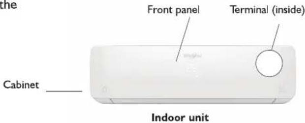
PRODUCT DESCRIPTION
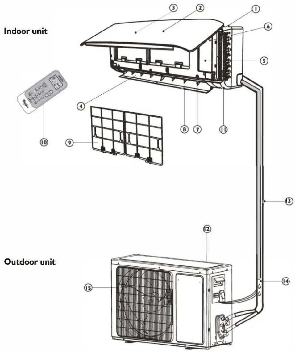
Indoor unit
I. Air Intake
2. Front Panel
3. Display panel
4. Air Outlet
5. Electrical box
6. Emergency control button
7. Vertical Adjustment Louver
8. Horizontal Adjustment Louver
9. Air Filter
10. Remote Control
II. On-off Switch
Images in the user instructions are based on external views of standard models, shape and design vary according to the model.
Outdoor unit
- Air Intake
- Pipes and Power Connection Cord
- Drain Hose
Note: Condensate water drains at COOLING or DRY operation.
- Air Outlet
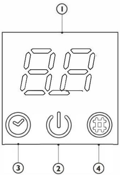
CONTROL PANEL DISPLAY INDICATORS DESCRIPTION

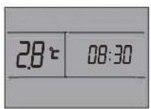
Temperature indicator (I)
Displays set temperature.
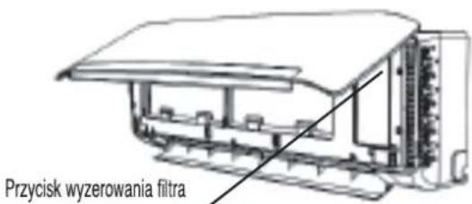
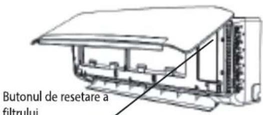
It shows "FC" as a reminder to clean the filter.

Running indicator (2)
It lights up during operation.
It flashes during outside unit defrosting.

Timer indicator (3)
It lights up during the set time.
It goes off when timer operation ends.

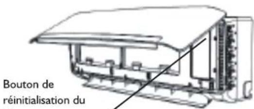
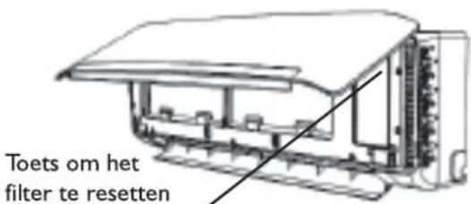
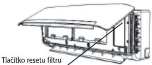
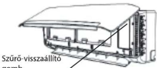
Filter monitor indicator (4)
It flashes when the filter needs to be cleaned.
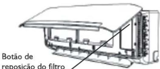
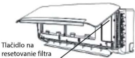
Filter monitor indicator flashes after 720 hours of usage as reminder to clean the filter.
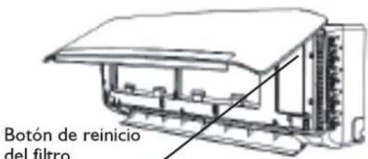
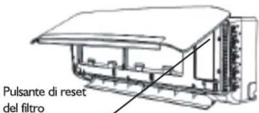
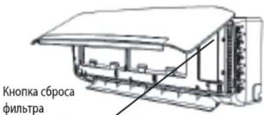
After filter cleaning, press the filter reset button located on the indoor unit behind the front panel in order to interrupt the flashing of the filter monitor indicator.
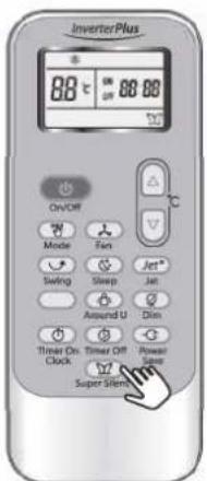
REMOTE CONTROL FUNCTIONS AND INDICATORS
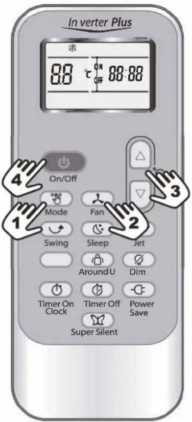
1. ON/OFF BUTTON
Starts and/or Stops the appliance by pressing this button.
2. MODE BUTTON
Used to select the operation mode.
3. FAN BUTTON
Used to select fan speed in sequence auto, high, medium or low.
4-5. TEMPERATURE BUTTON
Used to select the room temperature. Used to set time in timer mode and real time clock.
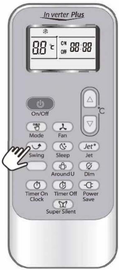
7. SWING BUTTON
Stops or starts vertical adjustment louver swinging and sets the desired up/down airflow direction.
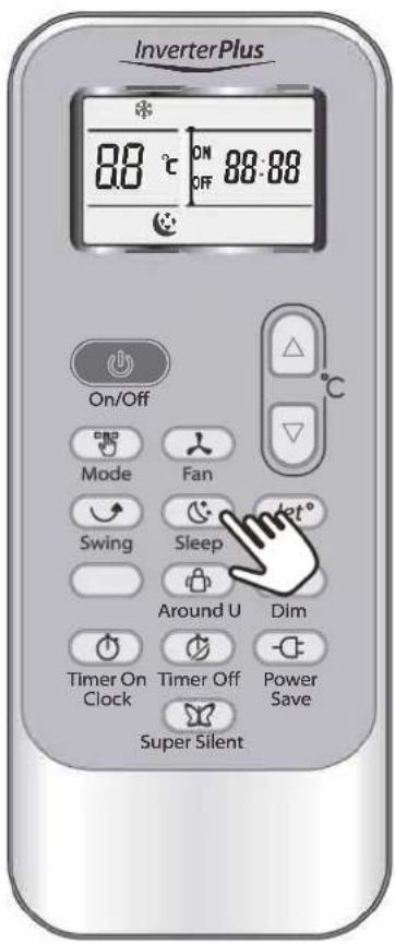
8. SLEEP BUTTON
Sets or cancels Sleep Mode operation.
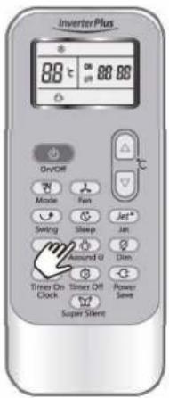
9. AROUND U BUTTON
When you press this button, the remote control transmits signal of the actual room temperature around itself to the indoor unit every 10 minutes. Therefore please keep the remote control in a location where it can transmit the signal to the indoor unit properly. Press once to set and press again to cancel.
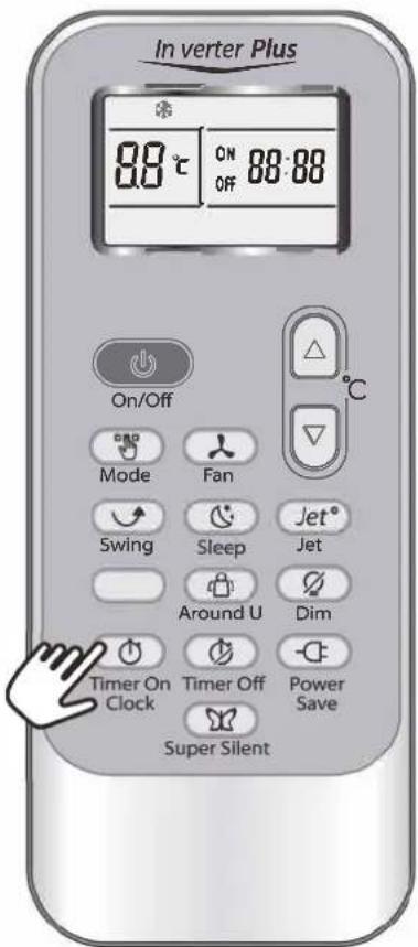
10. TIMER ON/CLOCK BUTTON
Used to set the current time.
Used to set or cancel the timer on operation.
II TIMER OFF BUTTON
Used to set or cancel the timer off operation.
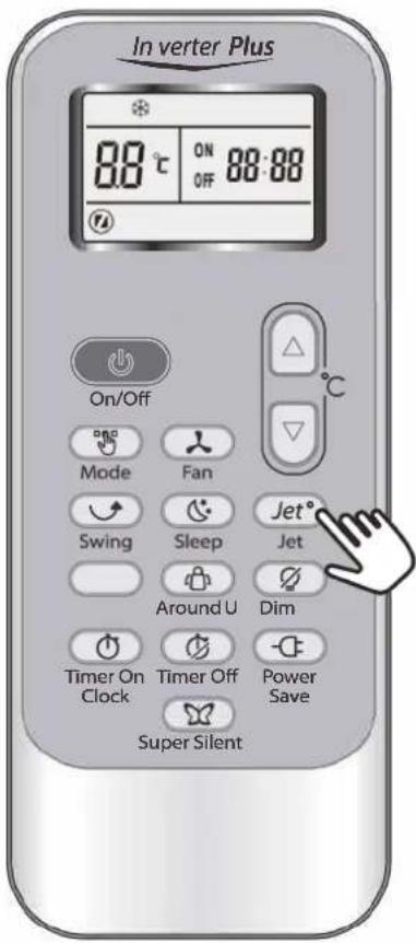
12. JET BUTTON
Used to start or stop the fast cooling.
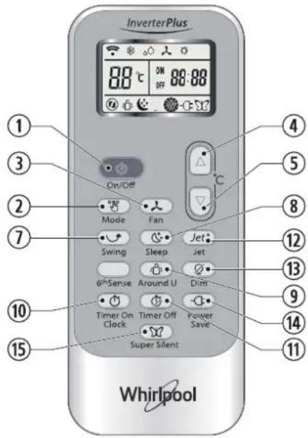
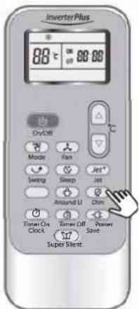
13. DIM BUTTON
Used to turn on or turn off display light on indoor unit.
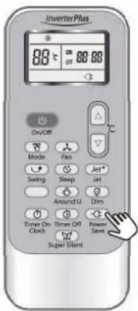
14. POWER SAVE BUTTON
Used to start or stop the power save operation.
15. SUPER SILENT BUTTON
Used to start or stop the super silent operation. This function is available only on certain models. Models without this function don't have the button on the remote control.
6th Sense function is not available for Free Match product, if click the 6th Sense button, the product will have no reaction.
INDICATOR SYMBOLS ON RC DISPLAY

Cooling indicator

Dry indicator

Fan only indicator

Heating indicator

Auto fan speed

High fan speed

Medium fan speed

Low fan speed

Super silent indicator

6th Sense indicator

Sleep I indicator (number of indicators depend on model)
Sleep 2 indicator (number of indicators depend on model)
Sleep 3 indicator (number of indicators depend on model)
Sleep 4 indicator (number of indicators depend on model)
Around U indicator
Jet indicator
Signal transmission
ON OFF 88:88 Display set timer
Display current time
88 ^r Display set temperature
Power save indicator
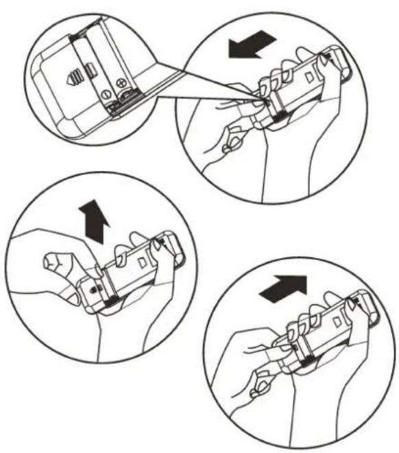
STORAGE AND TIPS FOR USING THE REMOTE CONTROL
How to insert the batteries
I. Insert a pin and gently press down on the battery cover and push in the direction of the arrow to remove, as shown.
- Insert 2 AAA batteries (1.5V) into the compartment.
Ensure that "+" and "-" polarity is correctly positioned.
- Close the battery cover on the remote control.
How to remove the batteries
Remove the battery cover in the direction of the arrow.
Press the positive pole of the battery softly with your fingers, then draw the batteries out of the compartment. All this should be done by adults, children are forbidden to remove the batteries from the remote control in order to avoid danger of swallow.
Disposal of the batteries
Please discard the batteries as sorted municipal waste at the accessible collection point.
Precautions
- When replacing the batteries, do not use new batteries with old batteries, or different types of batteries as this may cause the remote control to malfunction.
- If you do not expect to use the remote control for some time, take the batteries out to prevent leakage of battery acid in the remote control.
- Operate the remote control within effective range. Keep the remote control at least 1 meter from any TV set or HI-FI equipment.
- If the remote control does not work normally, take the batteries out and reinstall after 30 seconds. If it still does not work install new batteries.
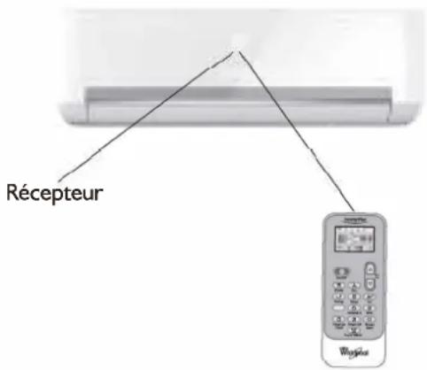
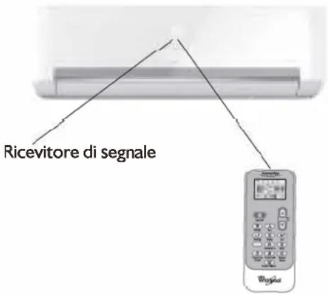
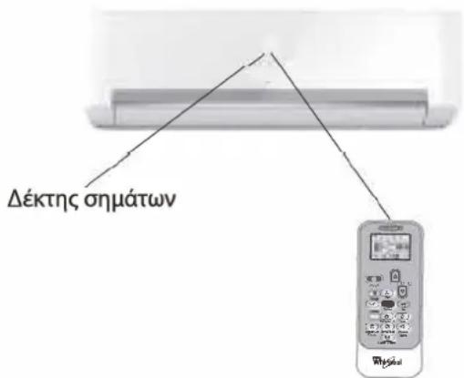
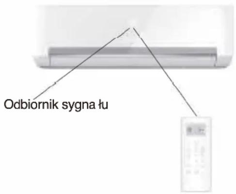
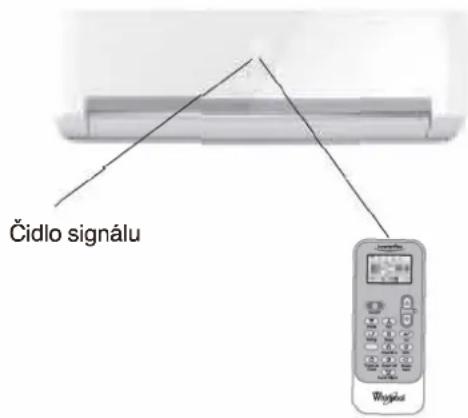
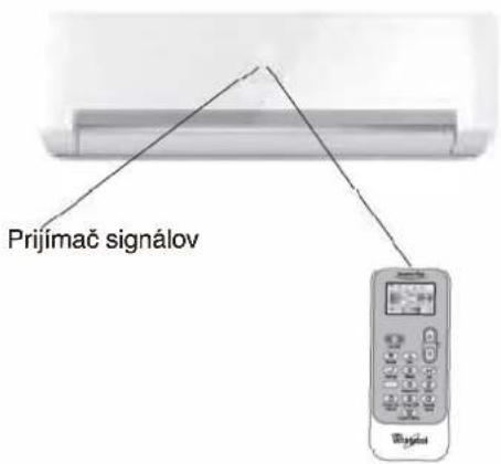
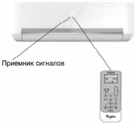
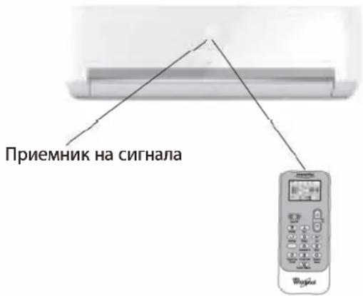
• To operate the appliance by remote control, point the remote control at the receiving device on the indoor unit, to ensure receiving sensibility.
• To send a message from remote control, the symbol 📤 will flash for 1 second. On receipt of the message, the appliance will emit a beep.
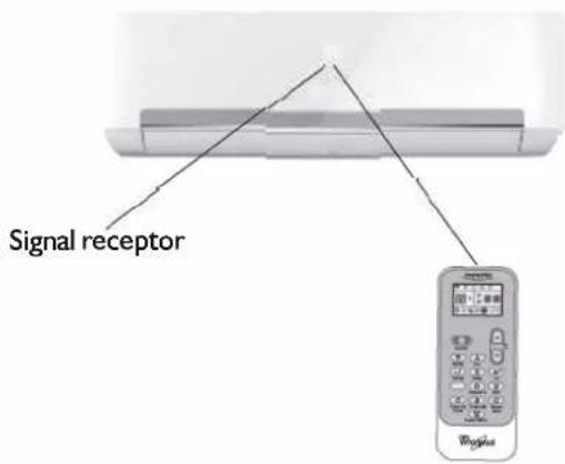
- The remote control will operate the air conditioner at a distance of up to 7m.
• Each time the batteries are replaced in the remote control, the remote control is pre-set at Heat Pump mode.
OPERATING MODE DESCRIPTION
Operation Modes:
I. Selecting mode
Each time MODE button is pressed, the operation mode is changed in sequence:
COOLING → DRY → FAN ONLY → HEATING
Heating mode is not available for cooling only conditioners.
2. FAN mode
Each time the "FAN" button is pressed, the fan speed is changed in sequence:
Auto → High → Medium → Low
At "FAN ONLY" mode, only "High", "Medium" and "Low" are available.
At "DRY" mode, Fan speed is set at "Auto" automatically, "FAN" button is ineffective in this case.
3. Setting temperature

Press once to raise temperature setting by I raise °C

Press once to lower temperature setting by I lower °C
| Range of available set temperature | |
| *HEATING, COOLING | 18 °C~32°C |
| DRY | +/-7°C |
| FAN ONLY | unable to set |
*Note: Heating mode is NOT available for cooling only models.
4. Turning on
Press button, when the appliance receives the signal, the RUNNING indicator of the indoor unit lights up.
During mode changes wait a few seconds and repeat the operation if the unit does not respond at once.
When selection the heating operation, air flow will start after 2-5 minutes.
AIRFLOW DIRECTION CONTROL
5. Airflow direction control
Vertical airflow is automatically adjusted to a certain angle in accordance with the operation mode after turning on the unit.
The direction of airflow can be also adjusted to your own requirement by pressing the "SWING" button of the remote control.
| Operation mode | Direction of airflow |
| COOLING, DRY | horizontal |
| *HEATING, FAN ONLY | downward |
*Heating mode is only available for heat pump models.
Vertical airflow control (using the remote control)
Use the remote control to set the flow angles.
Swinging airflow
Pressing "SWING" button once, the vertical adjustment louver will swing up and down automatically.
Desired direction airflow
Pressing the "SWING" button again when the louvers swing to a suitable angle as desired.
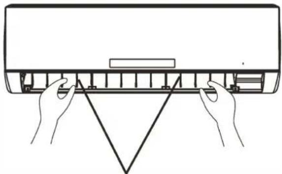
Horizontal airflow control (with hands)
Turn the control rods of the horizontal adjustment louvers to change horizontal air flow as shown.
Note: The shape of the unit may look different from that of the air conditioner you have selected.
A - Do not turn the vertical adjustment louvers manually, otherwise malfunction may occur. If that happens, turn off the unit first and cut off the power supply, then restore power supply again.
B - It is better not to let the vertical adjustment louver tilt downward for a long time at COOLING or DRY mode to prevent condensed water from dripping.
natural_image
Line drawing of hands installing or adjusting a component on a wall (no text or symbols)control rod of vertical adjustment louvers
MODE AND FUNCTION DESCRIPTIONS
Clock function
You can adjust the real time by pressing TIMER ON/CLOCK button, then using △ and ▶ buttons to get the correct time, press this button again, the real time is set.
SLEEP mode
SLEEP mode can be set in COOLING,
HEATING or DRY operation mode.
This function gives you a more comfortable environment for sleep.
The appliance will stop operation automatically after operating for 8 hours.
Fan speed is automatically set at low speed.
Each time SLEEP button is pressed, the operation mode is changed in sequence:
SLEEP 1→SLEEP 2→SLEEP 3→SLEEP 4→NORMAL

SLEEP for Adults (mode I)
Set temperature will rise by 2^ C at most if the appliance operates in cooling mode for 2 hours constantly, then keeps steady.
Set temperature will decrease by 2^ C at most if the appliance operates in heating mode for 2 hours constantly, then keeps steady.
SLEEP for Elderly (mode 2):
Set temperature will rise by 2^ C if the appliance operates in cooling mode for 2 hours constantly, decrease by ^ C after 6 hours, then decrease by 1^ C after 7 hours.
Set temperature will decrease by 2^ C if the appliance operates in heating mode for 2 hours constantly, rise by ^ C after 6 hours, then rise by 1^ C after 7 hours.
SLEEP for Youngsters/Teenagers (mode 3):
Set temperature will rise by 1°C if the appliance operates in cooling mode for 1 hour, rise by 2°C after 2 hours, then decrease by 2°C after 6 hours, decrease by °C after 7 hours.
Set temperature will decrease by 2^ C if the appliance operates in heating mode for 1 hour, decrease by 2^ C after 2 hours, then rise by 2^ C after 6 hours, rise by 2^ C after 7 hours.
SLEEP for Children (mode 4):
Set temperature will keep steady.
Note: Heating is NOT available for cooling only air conditioner.
JET mode
- JET mode is used to start or stop fast cooling or Heating.
Fast cooling operates at high fan speed, changing the set temperature automatically to 18°C.
Fast heating operates at auto fan speed, changing the set temperature automatically to 32 °C. - In JET mode, you can set airflow direction or timer. If you want to quit from JET mode, press any - JET, MODE, FAN, ON/OFF or TEMPERATURE SETTING button, the display will return to the original mode.
Note:
- SLEEP and 6th Sense buttons are not available in JET mode.
- The appliance will continue working in JET mode if you don't quit from it by pressing any of the buttons mentioned.
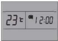
Timer function
It is convenient to set the timer on by pressing the TIMER ON/CLOCK button to achieve a comfortable room temperature at the time you get home.
You can also set timer off by pressing the TIMER OFF button to enjoy a good sleep at night.
How to set TIMER ON
TIMER ON/CLOCK button can be used to set the timer programming as wished in order to switch on the appliance at your desired time.
i) Press TIMER ON/CLOCK button for 3 seconds, when "ON 12:00" flashes on the LCD, then you can press the 🔒 or 📋 buttons to select your desired time for appliance on.
Press the ☐ or ☑ button once to increase or decrease the time setting by 1 minute. Press the ☐ or ☑ button for 5 seconds to increase or decrease the time setting by 10 minutes.
Press the 🔒 or 📋 button for a longer time to increase or decrease the time by 1 hour.
Note: If you don't see the time in 10 seconds after you press TIMER ON/CLOCK button, the remote control will exit the TIMER ON mode automatically.
ii) When your desired time displayed on LCD, press the TIMER ON/CLOCK button and confirm it.
A "beep" can be heard.
"ON" stops flashing.
The TIMER indicator on the indoor unit lights up.
iii) After the time set displayed for 5 seconds the clock will be displayed on the LCD of the remote control instead of set timer.
How to cancel TIMER ON
Press the TIMER ON/CLOCK button again, a "beep" can be heard and the indicator disappears, the TIMER ON mode has been canceled.
Note: It is similar to set the TIMER OFF, you can make the appliance switch off automatically at your desired time.
Increase
Decrease
Around U function
When you press this button, 📋 will display, remote control transmits the actual room temperature around it to the indoor unit, and the appliance will operate according to this temperature to let you feel more comfortable. Please keep the remote control in a location where it can transmit the signal to the indoor unit properly. Press once to set and press again to cancel.
DIM function
Press this button to turn on or turn off display light on indoor unit control panel.
POWER SAVE function
POWER SAVE mode can be available in COOLING, HEATING, DRY and FAN ONLY operation mode.
When pressing this button, ⏻ will display on remote control.
POWER SAVE function under COOLING, HEATING and DRY mode, the appliance will set the temperature at 25 °C with low fan speed. POWER SAVE function under FAN ONLY mode: the appliance will set at low fan speed.
Change mode or press the power save button again to cancel this function.
Note: Fan speed and temperature can not be adjusted under this mode.
SUPER SILENT function
Press 📋 button to let the unit operate at low noise level to get a quiet and comfortable room environment. 📋 will display on remote control.
Note: Super silent function 📋 will be off when pressing MODE button, or pressing SUPER SILENT button again.
This function may not be available on some models.
EMERGENCY OPERATION
Under emergency situation or when remote control is missing, you can control the unit by pressing the on/off switch located on the indoor unit.
- Turn on the appliance: when the unit is off, press this button, it will operate in the mode before the unit was turned off. (For the first operation after the installation, the default setting is in cooling mode at 18 °C, auto fan.)
- Turn off the appliance: when the unit is on, press this button, the unit will stop working.
PROTECTION
Operating condition
The protective device maybe trip and stop the appliance in the cases listed below.
| Heating | Outdoor air temperature is over 24°C |
| Outdoor air temperature is below -10°C | |
| Room temperature is over 27°C | |
| Cooling | Outdoor air temperature is over *43°C |
| Room temperature is below 21°C | |
| Dehumidifying | Room temperature is below 18°C |
*For Tropical (T3) Climate condition models, the temperature point is 52°C instead of 43°C. If the air conditioner runs in COOLING or DRY mode with door or window opened for a long time when relative humidity is above 80%, dew may drip down from the outlet.
Noise pollution
• Install the appliance at a place that can bear its weight in order to operate more quietly
• Install the outdoor unit at a place where the air discharged and the operation noise would not disturb your neighbours.
- Do not place any obstacles in front of the air outlet of the outdoor unit lest it increases the noise level.
Features of protection device
Wait at least 3 minutes before restarting the unit after operation stops or changing mode during operation. After connecting to power supply and turning on the appliance immediately, a delay of 20 seconds may occur before it starts to operate. If all operation has stopped, press ON/OFF button again to restart. Timer should be set again if it has been cancelled.

Features of COOLING mode
Anti-freezing
When the temperature of the indoor heat exchanger drops to 0^ or below, compressor will stop working to protect the appliance.
Features of HEATING mode
Preheating
In order to prevent cool air blowing, 2-5 minutes are necessary to preheat the indoor unit at HEATING operation start. The indoor fan will not work during preheating.
Defrosting
In HEATING operation the appliance will defrost (de-ice) automatically to raise efficiency. This procedure usually lasts 6-10 minutes. During defrosting, fan stops running and running indicator flashes. After defrosting is completeed, it returns to HEATING mode automatically.
Mode interfere
For the reason that all the indoor units use one outdoor unit, outdoor unit can only run with same mode (cooling or heating), so when the mode you set is different from the mode that the outdoor is running with, mode interfere occurs. Following shows the mode interfere scene.
| cooling | dry | heating | fan | |
| cooling | v | v | x | v |
| dry | v | v | x | v |
| heating | x | x | v | x |
| fan | v | v | x | v |
x: mode interfere - v: normal
Outdoor unit always run with the mode of first indoor unit that turned on. When the setting mode of following indoor unit is interfered with it, 3 beeps would be heard, and the indoor unit interfered with the normal running units would turn off automatically.
MAINTENANCE
Clean front panel of Indoor Unit
I. Disconnect from the power supply
Turn off the appliance first before disconnecting from power supply.
- Remove the front panel
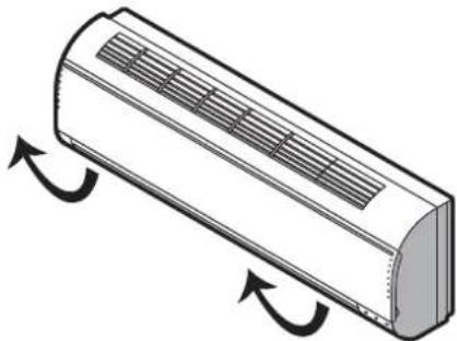
Open the front panel as shown by the arrow (Fig. A).
Pull the slots at the side of the front panel with force to take out the front panel (Fig. B).
- Clean the front panel
Wipe it with a soft and dry cloth. Use lukewarm water (below 40°C) to clean if the appliance is very dirty. After cleaning let it dry.
- Refit and close the front panel
Refit and close the front panel by pushing it downward.
Note:
- Do not use substances such as gasoline or polishing powder to clean the appliance.
- Do not sprinkle water onto the indoor unit Dangerous! Electric shock!
Clean Air filter
It is necessary to clean the air filter after using it for about 720 hours. Clean the air filter every two weeks if the air conditioner operates in an extremely dusty environment.
I. Disconnect from the power supply
Turn off the appliance first before disconnecting from power supply.
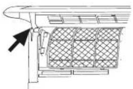
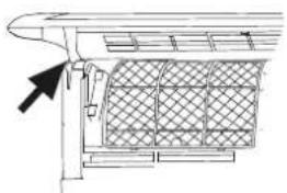
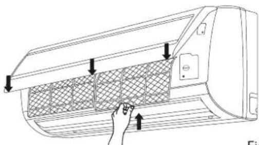
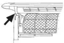
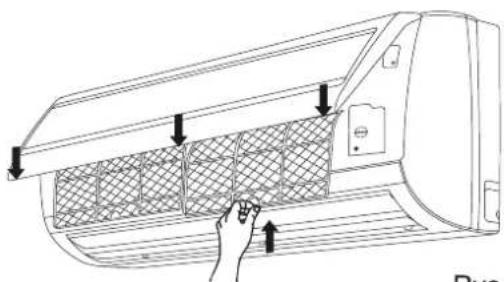
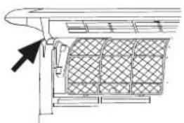
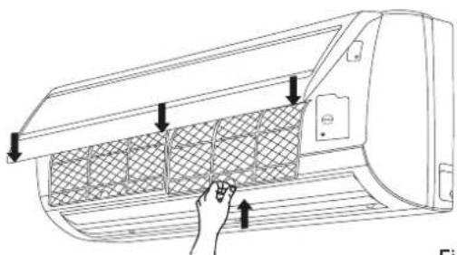
- Take out air filter (Fig. C).
I. Open the front panel.
2. Press the handle of the filter gently.
3. Slide out the filter.
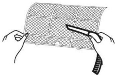
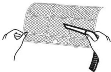
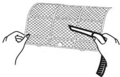
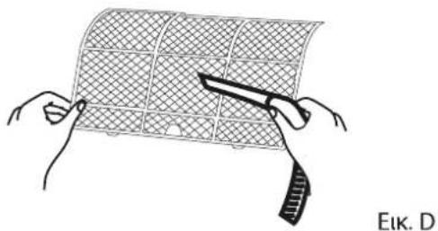
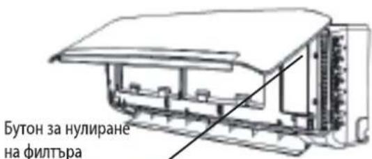
- Cleaning the air filter (Fig. D)
If the filter is very dirty, clean it with a solution of lukewarm water and neutral detergent. After cleaning let it dry.
- Refit the filter, press the filter reset button (Fig.E) at right side by using a cylinder pin and close the front panel.
Note:
• To avoid injury, do not touch the fins of indoor unit with your fingers after removing the filter.
- Do not attempt to clean the inside of the air conditioner by yourself.
- Do not clean the filter in washing machine.
natural_image
Diagram of a cylindrical air conditioner unit with airflow arrows indicating airflow direction (no text or symbols)Fig. A
natural_image
Technical line drawing of a mechanical component with a grid-patterned panel and an arrow pointing to it (no text or symbols)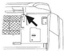
natural_image
Line drawing of a door panel with a black arrow pointing to the handle (no text or symbols)Fig. B

natural_image
Diagram of a car air conditioner unit with hand inserting a grid into the air gap (no text or symbols)Fig. C
natural_image
Illustration of two hands holding a grid-patterned sheet with a tool, no text or symbols presentFig. D
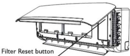
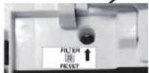
Fig. E
TROUBLESH DING
Operation problems are often due to minor causes, please check and refer to the following chart before contacting the service. This may save time and unnecessary expenses.
| Trouble | Analysis |
| Does not run | Is the protection device or fuse blown?Please wait for 3 minutes and start again, protection device may be preventing unit to work.Are the remote control batteries low?Is the plug not properly plugged? |
| No cooling or heating air | Is the air filter dirty?Are the intakes and outlets of the air conditioner blocked?Is the temperature set properly?Are doors or windows open? |
| Ineffective control | Has there been a strong interference (from excessive static electricity discharge, power supply voltage abnormality)? Note that operation will be abnormal, in this case unplug from the power supply and re-plug after 2-3 seconds. |
| Does not operate immediately | 3 minute delay will occur when changing mode during operation. |
| Peculiar smell | This smell may come from another source such as furniture, cigarette etc, which is sucked in the unit and blown out with the air. |
| A sound of running water | Normal behaviour caused by the flow of refrigerant in the air conditioner.Defrosting sound in heating mode. |
| Cracking sound | The sound may be generated by the expansion or contraction of the front panel due to temperature changes. |
| Mist sprays from the outlet | Mist is present in the room with low temperature? Normal behaviour due to cool air discharged from indoor unit during COOLING or DRY operation mode. |
| Running indicator flashes but indoor fan stops. | The unit is shifting from heating mode to defrost. The indicator will light off and return to heating mode. |
Note: If the problems still have, turn off the appliance and disconnect from power supply, then contact the nearest Whirlpool Authorized Service Center. Do not attempt to move, repair, disassemble, or modify the appliance by yourself.
INS TALLAT ON SERVICE
Before installation
I. Please read this manual carefully before installation.
2. The appliance must be installed according to national wiring rules and according to this manual by qualified technicians.
3. Any change of installation position must be handled by professionals;
4. Check the product to verify that it has not been damaged before installation.
- Mount with the lowest moving parts of indoor unit at least 2.5m above floor or grade Level.
- After installing, the consumer must operate the appliance correctly according to this manual, keep a suitable storage for maintenance and move of it in the future.
SAFETY PRECAUTION
I. The power supply must be of rated voltage with special circuitry for the appliance. The normal operating range of voltage is 90%\~110% of rated voltage. The diameter of the power cord must comply with requirements.
- The user power supply shall have a reliable grounding terminal. It is prohibited to connect the grounding wire to the following items:
I) Water Supply Pipe
2) Gas Pipe
3) Sewage Pipe
4) Other positions that are considered unsafe.
- Ensure safe grounding and a grounding wire connected with the special grounding system of the building, installed by professionals. The appliance must be fitted with electrical leakage protection switch and an auxiliary circuit breaker with sufficient capacity. The circuit breaker must also have a magnetic and a thermal tripping function to ensure protection in case of short-circuit and overload.
| Type | Model | Required Capacity of air break switch |
| Split Inverter | 20K | 30A |
| 24K | 30A | |
| 36K | 40A |
SAFETY PRECAUTION
- Make sure that the power supply cord is long enough to allow the right connection. Do not use any extension cord for power supply.
- If the supply cord is damaged, it must be replaced by the manufacturer or its service agent or a similarly qualified person in order to avoid a hazard;
- An all-pole disconnection switch having a contact separation of at least 3mm in all poles should be connected in fixed wiring.
- Risk of electric shock can cause injury or death: Disconnect all electric power supplies before servicing.
-
The connection of power cord and the cable connection between indoor unit and outdoor unit shall be in accordance with the wiring diagram attached on the appliance.
-
Once installation is completed, the electric components must not be accessible to the users.
- Use two or more people to move and install the appliance to avoid excessive weight hazard.
II. After unpacking the air conditioner, keep all packaging materials well out of the reach of must also have a magnetic and a thermal children. - According to the character of refrigerant the pressure of the tube is very high, so be sure to careful when you install and repair the appliance.
- A residual current device(RCD) having rated residual operation current not exceeding 30mA shall be incorporated in fixed wiring according to national law.
INSTALLATION INSTRUCTIONS
Installation diagram
Outdoor unit
NOTE: The figure above is only a simple presentation of the unit, it may not match the external appearance of the product you purchased. Installation must be performed in accordance with the national wiring standards by authorized service people only.
Select the best location
Location for Installing Indoor Unit
- Where there is no obstacle near the air outlet and air can be easily blown to every corner of room.
- Where piping and wall hole can be easily arranged.
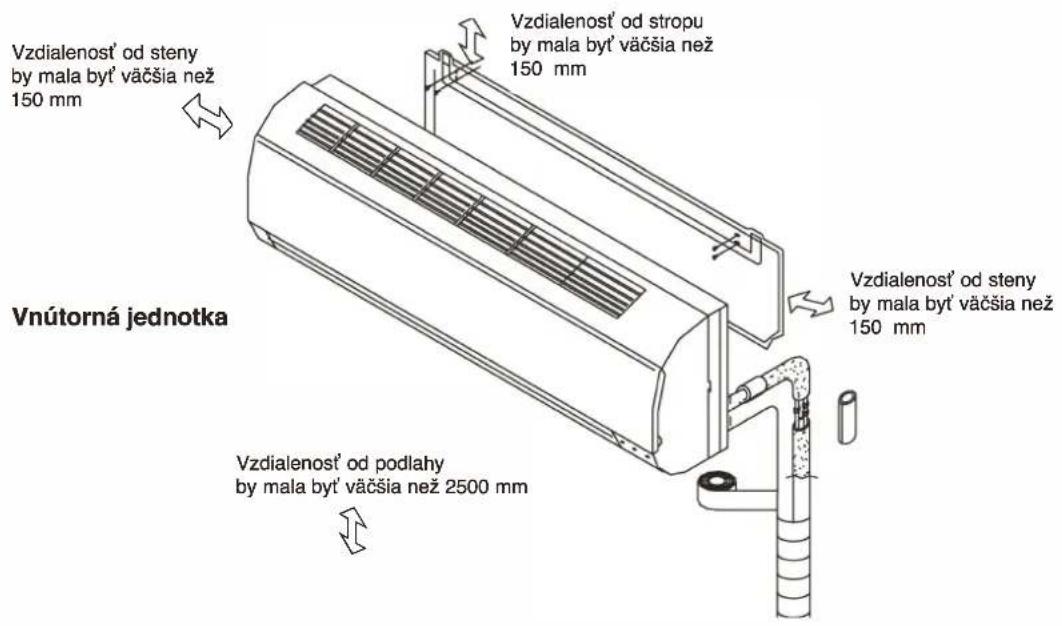
- Observe the required distance from ceiling and wall according to the installation diagram.
• Where the air filter can easily be removed. - Keep the unit and remote control 1m or more from television, radio etc.
• To prevent the effects of a fluorescent lamp, keep the unit as far as possible from it. - Do not put anything near the air inlet that could obstruct it.
- In a place that can bear the weight and will not increase operating noise and vibrations.
- The indoor unit is not suitable to be installed in areas used for laundry.
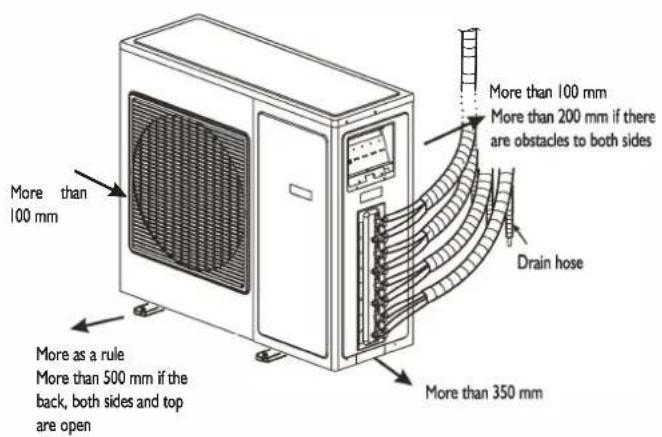
Location for Installing Outdoor Unit
• Install in a convenient and well-ventilated place.
- Avoid installing it where flammable gas could leak.
- Observe the required distance from the wall according to the installation diagram.
- The distance between Indoor and outdoor unit should be 5 meters and can go up to maximum 15 meters with additional refrigerant charge.
- Do not install the outdoor unit in a dirty or greasy place, near a vulcanization gas exit.
- Avoid installing it at the roadside where it could be soiled with muddy water.
- A fixed base where operating noise will not increase.
• Where the air outlet is not obstructed.
- The installation position shall be able to withstand the weight and vibration of the outdoor unit and ensure safe installation;
- Where drained water does not become any problem.
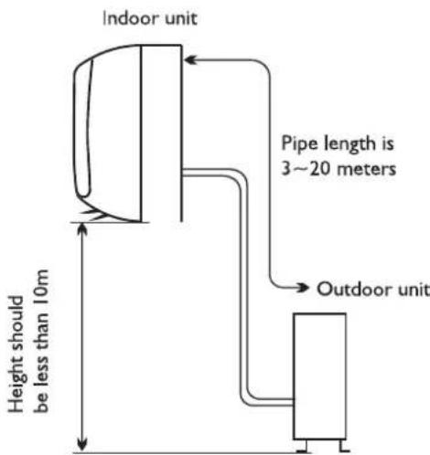
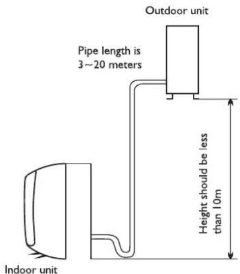
| Model | Standard tubing Length (m) | Limit of Each Indoor Unit Tubing Length (m) | Limit of Total Tubing Lenght (m) | Limit of Elevation Difference H (m) | Extra refrigerant charge (g/m) |
| 20K | 5+5+5 | 20 | 60 | 10 | 15 (When total piping length is over 15m) |
| 24K | 5+5+5 | 20 | 60 | 10 | 15 (When total piping length is over 20m) |
| 36K | 5+5+5+5 | 25 | 60 | 10 | 15 (When total piping length is over 20m) |
INDOOR UNIT INSTALLATION
I. Installing the Mounting Plate
- Select a location to install the mounting plate according to the indoor unit location and piping direction.
- Adjust the mounting plate horizontally with a gradienter or plumb line.
- Drill holes 32mm in deep on the wall to fix the plate.
- Insert the plastic plugs in the hole, then fix the mounting plate with tapping screws.
- Check that the mounting plate is well fixed. Then drill a hole for piping.
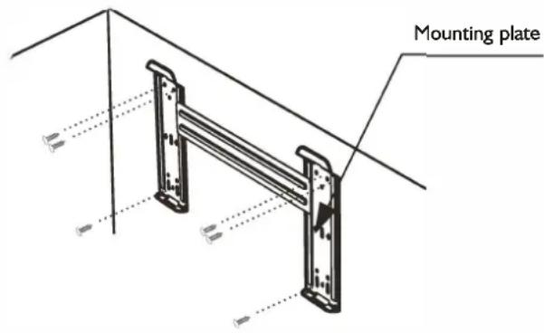
NOTE: The shape of your mounting plate may be different from the one above, but installation method is similar.
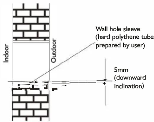
2. Drill a Hole for Piping
- Decide the position of the hole for piping according to the location of mounting plate.
- Drill a hole on the wall. The hole should slightly be inclined downward toward outside.
• Install a sleeve through the wall hole to keep the wall tidy and clean.
3. Indoor Unit Piping Installation
- Fit the piping (liquid and gas pipe) and cables through the wall hole from outside or fit them from inside after completing indoor piping and cables connections so as to connect to outdoor unit.
- Decide whether saw off the plastic part in accordance with the piping direction (as shown below).
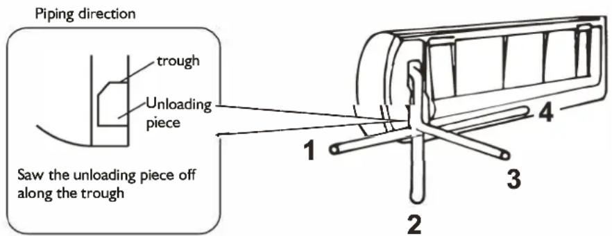
NOTE:
When fixing the pipe along directions 1, 2 or 4, saw the corresponding plastic part off the indoor unit base.
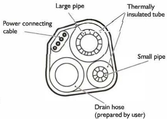
- After connecting the piping as required, install the drain hose. Then connect the power connecting cable. After connecting, wrap the piping, cable and drain hose together with thermal insulating materials.
NOTE: Do not connect to power supply during installation.
IMPORTANT:
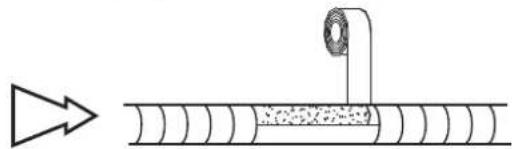
Piping Joints Thermal Insulation:
Wrap the piping joints with thermal insulating materials and then wrap with a vinyl tape.
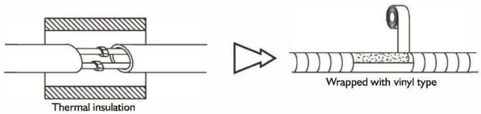
Thermal Insulation piping:
a. Place the drain hose under the piping.
b. Insulation material: polythene foam over 6mm in thickness.
NOTE: Drain hose is prepared by user.
- Drain hose should point downward for easy drain flow. Do not twist the drain pipe, leave it sticking out or waving around, do not immerse the end in water. If an extension drain hose is connected to the drain pipe, make sure to be thermally insulated when passing it through the indoor unit.
- When the piping is directed to the right, piping, power cable and drain hose should be thermally insulated and fixed at the rear of the unit.
Piping Connection:
a. Connect indoor unit pipes with two wrenches. Pay special attention to the torque allowed as shown below to prevent the pipes, connectors and flare nuts from being deformed and damaged.
b. At first fingers-tighten them, then use the wrenches.
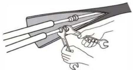
natural_image
Illustration of hands using a tool to adjust or install a mechanical component (no text or symbols present)| Pipe size | Torque | Nut width | Min. thickness |
| Liquid Side (1/4 inch) | 1.5~2kg.m | 17mm 0.5mm | |
| Gas Side (3/8 inch) | 3.1 ~3.5kg.m | 22mm 0.7mm | |
| Gas Side (1/2 inch) | 5.0~5.5kg.m | 24mm 0.8mm | |
| Gas Side (5/8 inch) | 6.0~6.5kg.m | 27mm 0.8mm |
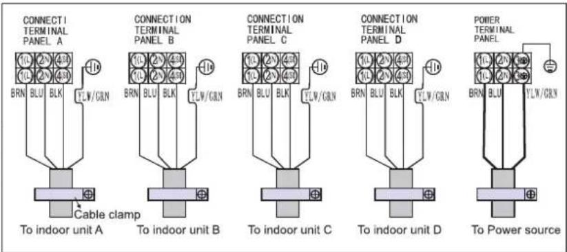
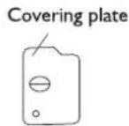
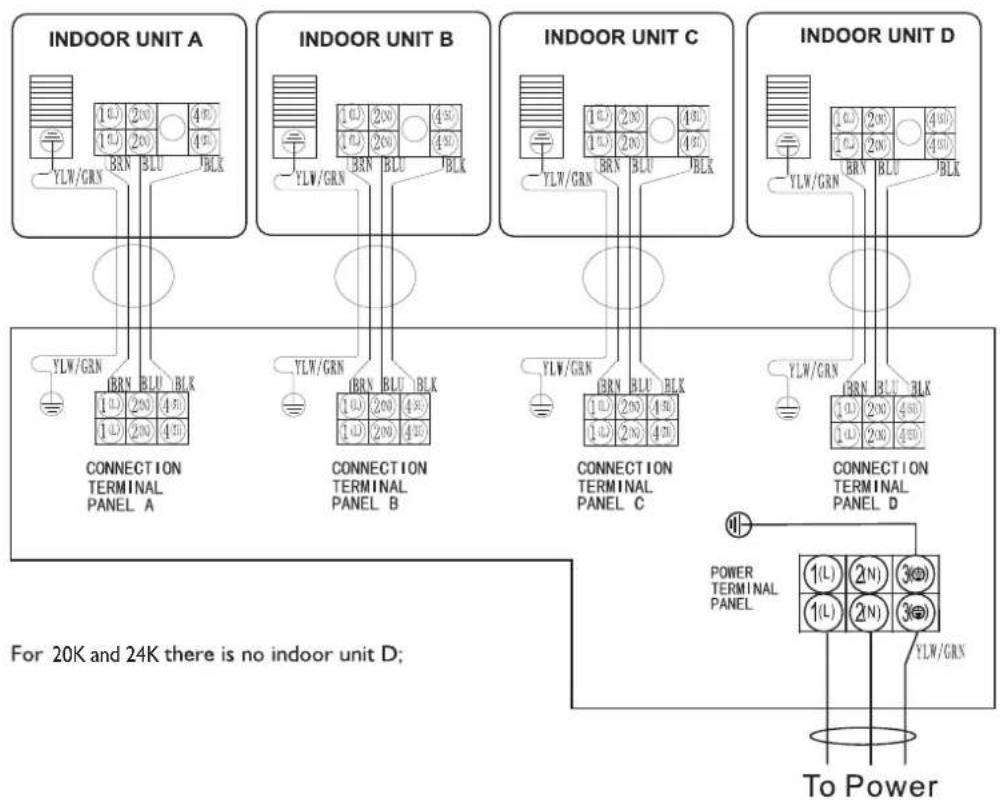
4. Connecting the Cable
- Indoor Unit
1) Open the front panel, remove the covering plate by loosening the screw.
2) Connect the power connecting cord to the indoor unit by connecting the wires to the terminals on the control board individually as follows.
3) Secure the power connecting cord on the control board with cable clamp.
4) Refit the covering plate and tighten the screw.
NOTE: (depending on the model) It is necessary to remove the cabinet to perform connections with the indoor unit terminal.
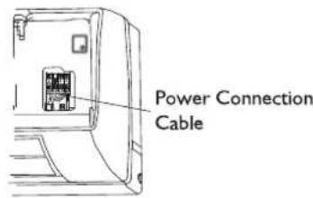
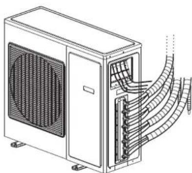
- Outdoor Unit
I) Remove the access door from the unit by loosening the screw. Unscrew the cable clamp, connect the wires to the terminals on the control board individually in accordance with the indoor unit connection.
2) Secure the power connecting cord on the control board with cable clamp.
3) Refit the access door in the original position and tighten the screw.
NOTE: (depending on the model) It is necessary to remove the cabinet to perform connections with the indoor unit terminal.
natural_image
Technical line drawing of an air conditioning unit with cooling fans and internal wiring (no text or symbols)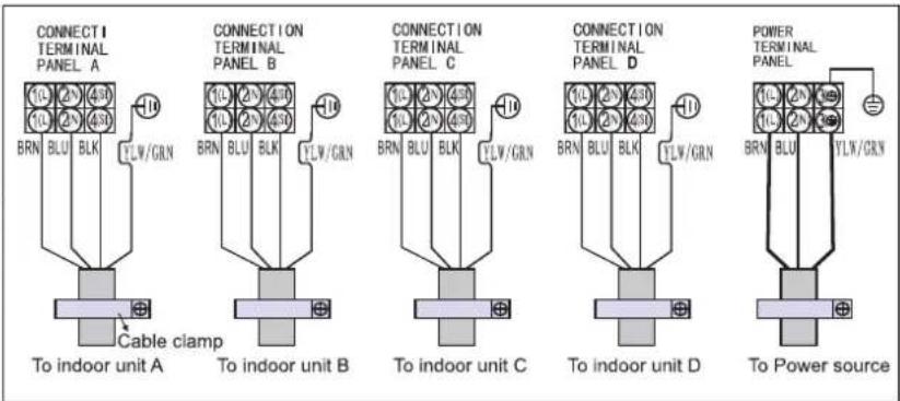
For 20K and 24K there is no indoor unit D;
CAUTION:
- Make sure that the colour of wires and the terminal number of the outdoor unit are the same as those of the indoor unit.
- Use an individual power circuit specifically for the air conditioner. As for the wiring method, refer to the circuit diagram on the appliance.
- Check that the cable specification conforms to the table as follows. And the minimum cross sectional area of the cable should comply with Design 245 IEC 57.
- Check the wires and make sure that they are all tightly fastened after cable connection. The cable should be tightly fastened by cable clamp.
- Be sure to install an earth leakage circuit breaker in a wet or moist area.
Cable Specifications
| Model | Power cord (outdoor) | Power connecting cable | Main powersupply (Note) |
| 20K | H05RN-F,3G 2.5mm ^2 | H07RN-F, 4G 0.75mm ^2 | To outdoor |
| 24K | H05RN-F,3G 4.0mm ^2 | H07RN-F, 4G 0.75mm ^2 | To outdoor |
| 36K | H05RN-F,3G 4.0mm ^2 | H07RN-F, 4G 0.75mm ^2 | To outdoor |
OUTDOOR UNIT INSTALLATION
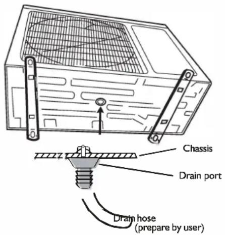
I. Install Drain Port and Drain Hose
The condensate drains from the outdoor unit when the unit operates in heating mode. In order not to disturb your neighbours and protect the environment, install a drain port and a drain hose to direct the condensate water. Just install the drain port on the chassis of the outdoor unit, then connect a drain hose to the port as shown in the figure on the right.
2. Install and Fix Outdoor Unit
Fix with bolts and nuts tightly on a flat and strong floor. If installed on the wall or roof, make sure to fix the supporter well to prevent it from shaking due to serious vibration or strong wind.
3. Outdoor Unit Piping Connection
- Remove the valve caps from the 2-way and 3-way valve.
- Connect the pipes to the 2-way and 3-way valves separately according to the required torque.
4. Outdoor Unit Cable Connection (see previous page)
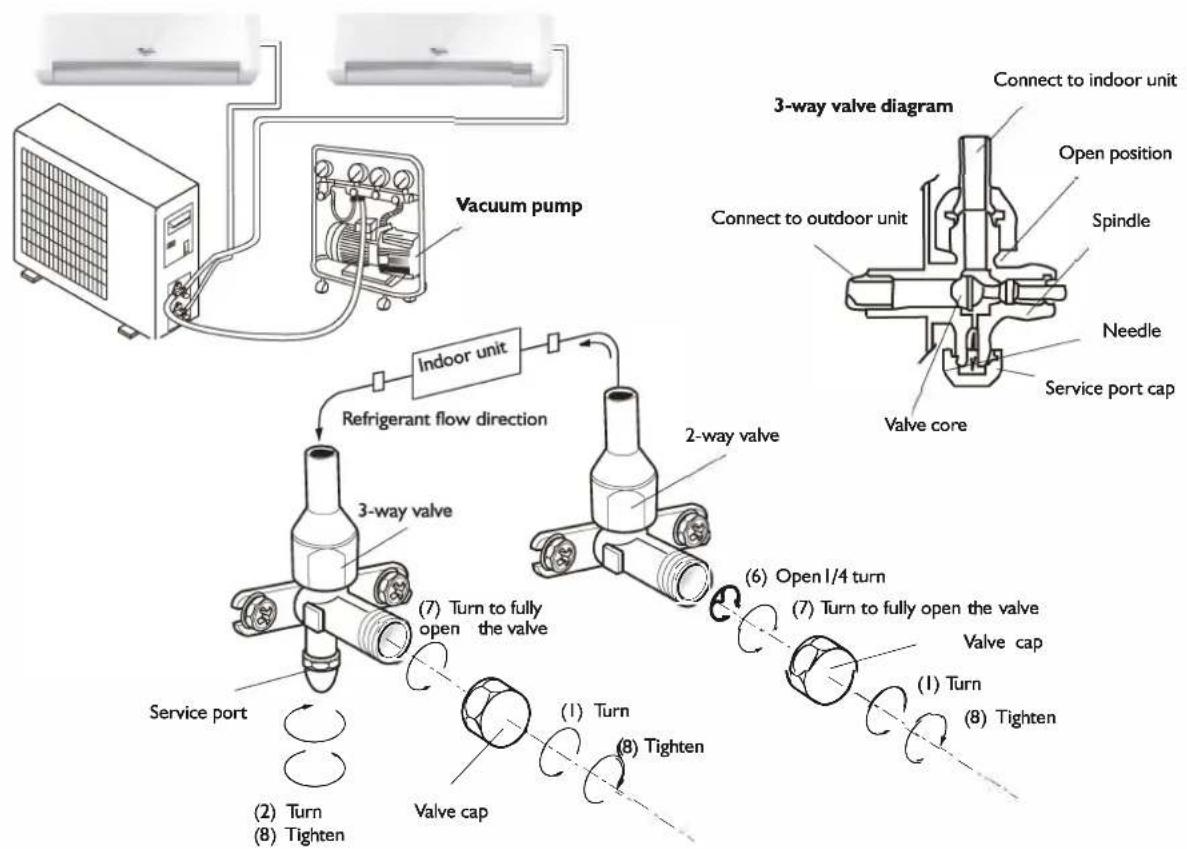
AIR PURGING
Air containing moisture remaining in the refrigeration cycle may cause a malfunction on the compressor. After connecting the indoor and outdoor units, evacuate air and moisture from refrigerant cycle using a vacuum pump, as shown below.
Note: Because the system pressure is high and also to protect the environment, be sure not to discharge the refrigerant to the air directly.
flowchart
graph TD
    A["Vacuum pump"] --> B["Indoor unit"]
    B --> C["3-way valve"]
    C --> D["2-way valve"]
    D --> E["3-way valve"]
    E --> F["Valve core"]
    F --> G["Valve cap"]
    G --> H["Tighten"]
    H --> I["Turn"]
    I --> J["Valve cap"]
    J --> K["Tighten"]
    K --> L["Turn to fully open the valve"]
    L --> M["Service port"]
    M --> N["Refrigerant flow direction"]
    N --> O["Connect to indoor unit"]
    O --> P["Open position"]
    P --> Q["Spindle"]
    Q --> R["Needle"]
    R --> S["Service port cap"]
How to Purge Air Tubes:
I. Unscrew and remove caps from 2 and 3-way valves.
2. Unscrew and remove cap from service valve.
3. Connect vacuum pump flexible hose to the service valve.
4. Start vacuum pump for 10-15 minutes until it reaches an absolute vacuum of 10 mm Hg.
5. With vacuum pump still running close the low pressure knob on vacuum pump manifold. Then stop vacuum pump.
6. Open 2-way valve 1/4 turn, then close it after 10 seconds. Check tightness of all joints using liquid soap or an electronic leak detector.
7. Turn 2 and 3-way valves stem. Disconnect vacuum pump flexible hose.
8. Replace and tighten all valve caps.
AFTER SALES SERVICE
Before contacting the Customer Care Centre:
- Try to solve the problem yourself based on the descriptions given in the "Troubleshooting".
- Turn the appliance off and restart it to see if the fault persists.
If after carrying out the above checks, the fault persists, contact the Customer Care Centre.
Please give:
- a short description of the fault;
• the exact model of the air conditioner; - the service number (this is the number found below the word Service on service sticker which is located on the side or on the bottom of the indoor unit).
The service number can also be found in the warranty booklet;
- your full address;
- your telephone number.
If repair work has to be carried out, contact the Customer Care Centre (Use of original spare parts and a proper repair is guaranteed).
You will need to present the original invoice.
Failure to comply with these instructions could compromise the safety and quality of your product.
SERVICE
0000 000 00000
AVANT D'UTILISER L'APPAREIL
7. TOUCHE SWING (Oscillation)
natural_image
Line drawing of hands installing or adjusting a component on a wall, with no text or symbols present.natural_image
Diagram of a cylindrical air conditioner unit with airflow arrows indicating direction (no text or symbols)Fig. A
natural_image
Technical diagram of a mechanical component with a grid-patterned panel and directional arrow (no text or symbols)
natural_image
Diagram of a vehicle door panel with an arrow pointing to the door handle (no text or symbols present)Fig. B
natural_image
Diagram of a car air vent with mesh insulation and directional arrows indicating airflow or movement (no text or symbols)Fig. C

natural_image
Illustration of two hands holding a grid-patterned sheet with scissors, no text or symbols presentFig. D
INSTRUCTIONS 'INSTALLATION
natural_image
Illustration of hands using a tool to adjust or install a mechanical component (no text or symbols visible)natural_image
Technical line drawing of a server unit with cooling fan and coiled cable (no text or symbols)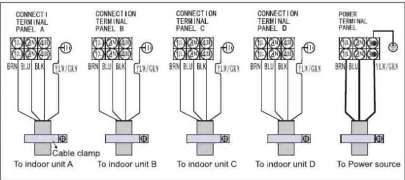
ATTENTION :
AFVALVERWERKING VAN HET APPARAAT

natural_image
Line drawing of hands installing or adjusting a component on a wall, forming a triangular shape (no text or symbols)SLEEP 1→SLEEP 2→SLEEP 3→SLEEP 4→NORMAAL

natural_image
Illustration of a cylindrical air conditioner with airflow arrows indicating direction (no text or symbols)Fig. A

natural_image
Technical line drawing of a mechanical component with a mesh pattern and an arrow indicating direction (no text or symbols)
natural_image
Diagram of a door panel with a black arrow pointing to the handle (no text or symbols present)Fig. B

natural_image
Diagram of a car air vent with mesh insulation and directional arrows indicating airflow or movement (no text or symbols)Fig. C

natural_image
Illustration of two hands holding a grid-patterned sheet with scissors, no text or symbols presentFig. D
INSTALLATIE BINNENUNIT
natural_image
Illustration of hands using a tool to lift a blade, no text or symbols present| Leidingdiameter | Koppel | Breedte moer | Min. dikte |
| Liquid Side (1/4 inch) | 1,5~2 kg.m | 17 mm | 0.5 mm |
| Gas Side (3/8 inch) | 3,1~3,5 kg.m | 22 mm | 0, 7 mm |
| Gas Side (1/2 inch) | 5,0~5,5 kg.m | 24 mm | 0,8 mm |
| Gas Side (5/8 inch) | 6,0~6,5 kg.m | 27 mm | 0,8 mm |
4. Kabel aansluiten
- Binnenunit
natural_image
Technical line drawing of an air conditioning unit with cooling fan and internal wiring (no text or symbols)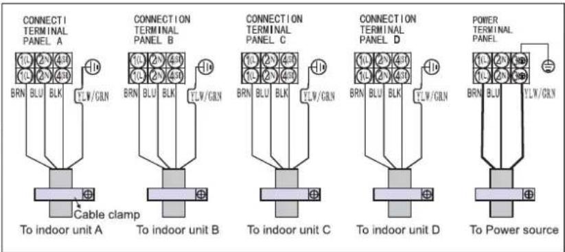
LET OP:
natural_image
Diagram of a computer monitor with ventilation grille and screw base, showing internal components and wiring (no text or symbols)LUCHT ZUIVEREN
Precauciones
natural_image
Line drawing of hands installing or adjusting a component on a wall, with no text or symbols presentnatural_image
Diagram of a cylindrical air conditioner unit with airflow arrows indicating direction (no text or symbols)Fig. A

natural_image
Technical line drawing of a mechanical component with a meshed panel and directional arrow (no text or symbols)
natural_image
Line drawing of a door panel with a black arrow pointing to the door handle (no text or symbols present)Fig. B

natural_image
Diagram of a car air conditioner unit with hand pointing to the interior panel (no text or symbols)Fig. C
natural_image
Illustration of two hands holding a grid-patterned sheet with a tool, no text or symbols presentFig. D
natural_image
Illustration of hands using a tool to lift a blade, no text or symbols presentnatural_image
Technical line drawing of an air conditioning unit with cooling fan and internal wiring (no text or symbols)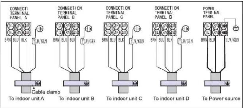
PRECAUCIÓN:
8. BOTAÔ SLEEP (NOITE)
Como colocar as pilhas
Precauções
natural_image
Line drawing of hands installing or adjusting a component on a wall, forming a triangular shape (no text or symbols)Barras de controlo das grelhas de ajuste horizontal
DESCRIÇÕES DOS MODOS E DAS FUNÇÕES
natural_image
Diagram of a cylindrical air conditioner with airflow arrows indicating direction (no text or symbols)Fig. A
natural_image
Technical line drawing of a mechanical component with a grid-patterned mesh structure and an arrow pointing to a feature (no text or symbols)
natural_image
Line drawing of a door panel with a black arrow pointing to the door (no text or symbols)Fig. B

natural_image
Diagram of a car air vent with a hand inserting a grid pattern into the vent (no text or symbols)Fig. C
natural_image
Illustration of two hands holding a grid-patterned sheet with scissors, no text or symbols presentFig. D
natural_image
Technical line drawing of a metal frame structure with mounting brackets and dimension lines (no text or symbols)natural_image
Illustration of hands using a tool to lift a curved blade (no text or symbols present)4. Ligação do cabo
- Unidade interior
natural_image
Technical line drawing of an air conditioning unit with cooling fans and internal wiring (no text or symbols)
CUIDADO:
natural_image
Line drawing of hands installing or adjusting a component on a device (no text or symbols)natural_image
Diagram of a cylindrical air conditioner unit with airflow arrows indicating direction (no text or symbols)Fig. A

natural_image
Technical line drawing of a mechanical component with a meshed panel and directional arrow (no text or symbols)
natural_image
Line drawing of a door panel with a black arrow pointing to the door handle (no text or symbols present)Fig. B

natural_image
Diagram of a car air vent with a hand pressing down on the vent (no text or symbols present)Fig. C

natural_image
Illustration of two hands holding a grid-patterned sheet with a tool, no text or symbols presentFig. D
natural_image
Illustration of hands using a tool to lift a mechanical component (no text or symbols present)natural_image
Technical line drawing of an air conditioning unit with cooling fans and internal wiring (no text or symbols)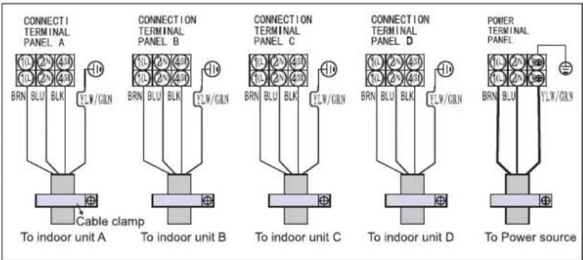
3. ΚΟΥΜΠΙ FAN (ΑΝΕΜΙΣΤΗΡΑΣ)
natural_image
Line drawing of hands installing or adjusting a component on a wall, with no text or symbols presentnatural_image
Illustration of a cylindrical air conditioner unit with airflow arrows indicating direction (no text or symbols)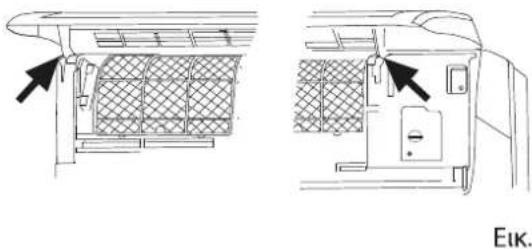
natural_image
Technical line drawing of a car air conditioner unit showing front and side views with no text or symbols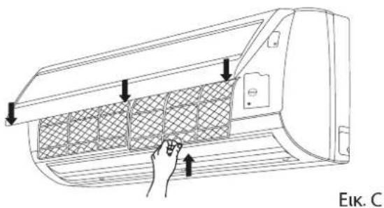
natural_image
Illustration of hands holding a grid-like object with scissors, no text or symbols present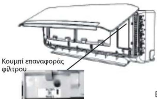
natural_image
Illustration of hands using a tool to adjust or install a mechanical component (no text or symbols visible)natural_image
Technical line drawing of an air conditioning unit with cooling fans and internal wiring (no text or symbols)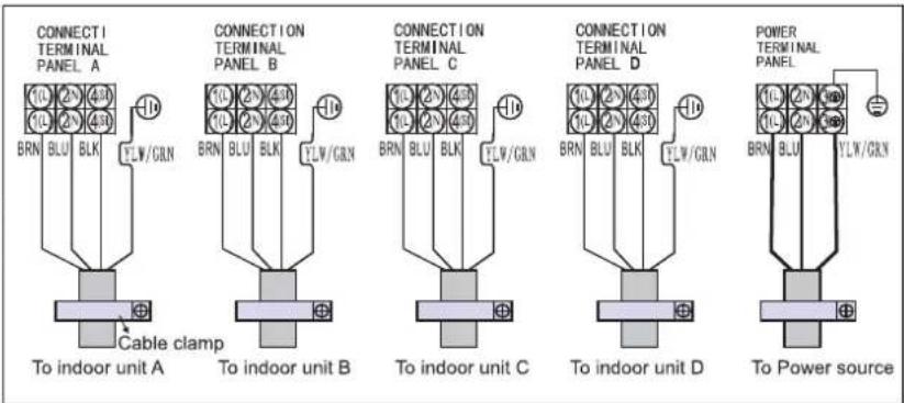
ΠΡΟΣΟΧΗ:
natural_image
Line drawing of hands installing or adjusting a component on a wall (no text or symbols)SLEEP 1→SLEEP 2→SLEEP 3→SLEEP 4→NORMAL

natural_image
Diagram of a cylindrical air conditioner unit with airflow arrows indicating direction (no text or symbols)Rys. A

natural_image
Technical line drawing of a mechanical component with a grid-patterned mesh structure and an arrow pointing to a feature (no text or symbols)
natural_image
Line drawing of a door panel with a black arrow pointing to the door handle (no text or symbols present)Rys. B
Rys. C

natural_image
Illustration of two hands holding a grid-patterned sheet with scissors, no text or symbols presentRys. D
natural_image
Illustration of hands using a tool to lift a curved blade, no text or symbols presentnatural_image
Technical line drawing of an air conditioning unit with cooling fans and internal wiring (no text or symbols)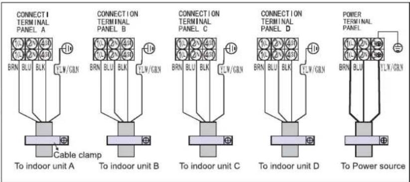
OSTRZEŻENIE:
FUNKCE A UKAZATELE DÁLKOVÉHO OVLADAČE
1. Tlačítko ON/OFF
POPIS PROVOZNÍCH REŽIMŮ
Provozní režimy:
1. Volba režimu
natural_image
Line drawing of hands installing or adjusting a component on a wall, with no text or symbols present.SLEEP 1→SLEEP 2→SLEEP 3→SLEEP 4→NORMAL

natural_image
Diagram of a cylindrical air conditioner unit with airflow arrows indicating airflow direction (no text or symbols)Obr. A

natural_image
Technical line drawing of a mechanical component with a meshed panel and directional arrow (no text or symbols)
natural_image
Diagram of a door panel with an arrow pointing to the door handle (no text or symbols present)Obr. B

natural_image
Diagram of a car air conditioner unit with hand pressing down on the panel (no text or symbols)Obr. C

natural_image
Illustration of two hands holding a grid-patterned sheet with a tool, no text or symbols presentObr. D
Obr. E
JAK ODSTRANIT ZÁVADU
natural_image
Illustration of hands using a tool to lift a blade, no text or symbols present| Rozměry trubky | Točivý moment | Velikost matice | Min. tloušťka |
| Strana s kapalinou (1/4 palce) | 1,5~2 kpm | 17 mm | 0,5 mm |
| Strana s plynem (3/8 palce) | 3,1~3,5 kpm | 22 mm | 0,7 mm |
| Strana s plynem (1/2 palce) | 5,0~5,5 kpm | 24 mm | 0,8 mm |
| Strana s plynem (5/8 palce) | 6,0~6,5 kpm | 27 mm | 0,8 mm |
4. Připojení kabelu
• Vnitřní jednotka
natural_image
Technical line drawing of an air conditioning unit with cooling fan and internal tubing (no text or symbols)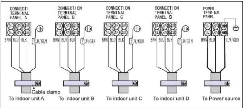
UPOZORNĚNÍ:
INSTALACE VENKOVNÍ JEDNOTKY
4-5. TLAČIDLO TEPLOTY
OPIS PREVÁDZKOVÉHO REŽIMU
Prevádzkové režimy:
1. Vol'ba režimu
natural_image
Line drawing of hands installing or adjusting a component on a wall, with no text or symbols presentSLEEP 1→SLEEP 2→SLEEP 3→SLEEP 4→NORMAL

natural_image
Illustration of a cylindrical air conditioner unit with airflow arrows indicating direction (no text or symbols on the diagram itself)
natural_image
Technical line drawing of a structural component with a mesh grid pattern and an arrow indicating direction (no text or symbols)
natural_image
Line drawing of a door panel with a black arrow pointing to the handle (no text or symbols)Obr. B

natural_image
Diagram of a car air vent with a hand inserting a grid into the air gap (no text or symbols)Obr. C

natural_image
Illustration of two hands holding a grid-patterned sheet with a tool, no text or symbols presentObr. D
Obr. E
ODSTRAŇOVANIE PROBLÉMOV
POKYNY NA INŠTALÁCIU
Inštalačná schéma
natural_image
Illustration of hands using a tool to lift a mechanical component (no text or symbols present)| Vel'kost'rúrky | Ut'ahovací moment | Širka matice | Minimálna hrúbka |
| Strana, kde bude prúdit' kvapalina (1/4 palca) | 1,5 ~ 2 kg.m | 17 mm | 0,5 mm |
| Strana, kde bude prúdit' plyn (3/8 palca) | 3, 1 ~ 3,5 kg.m | 22 mm | 0,7 mm |
| Strana, kde bude prúdit' plyn (1/2 palca) | 5,0 ~ 5,5 kg.m | 24 mm | 0,8 mm |
| Strana, kde bude prúdit' plyn (5/8 palca) | 6,0 ~ 6,5 kg.m | 27 mm | 0,8 mm |
4. Zapojenie kábla
natural_image
Technical line drawing of an air conditioning unit with cooling fan and internal wiring (no text or symbols)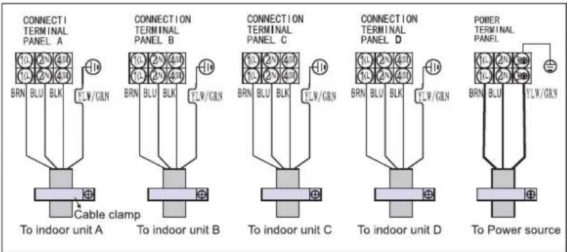
UPOZORNENIE:
Óvintézkedések
natural_image
Line drawing of hands installing or adjusting a component on a device (no text or symbols present)SLEEP 1→SLEEP 2→SLEEP 3→SLEEP 4→NORMAL ↑
natural_image
Diagram of a cylindrical air conditioner unit with airflow arrows indicating airflow direction (no text or symbols)A ábra
natural_image
Technical line drawing of a mechanical component with a meshed panel and an arrow indicating direction (no text or symbols)
natural_image
Line drawing of a door with a black arrow pointing to the door panel (no text or symbols)B ábra

Cábra

natural_image
Illustration of two hands holding a grid-patterned sheet with a tool, no text or symbols presentD ábra
natural_image
Illustration of hands using a tool to lift a blade, no text or symbols presentnatural_image
Technical line drawing of an air conditioning unit with cooling fans and internal wiring (no text or symbols)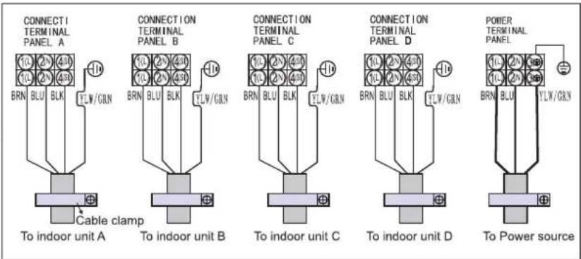
FIGYELEM:
natural_image
Line drawing of hands installing or adjusting a component on a wall, with no text or symbols presentnatural_image
Diagram of a curved air conditioner unit with airflow arrows indicating direction (no text or symbols)Рис. А

natural_image
Technical line drawing of a mechanical component with a meshed panel and an arrow indicating direction (no text or symbols)
natural_image
Line drawing of a door with a black arrow pointing to the door panel (no text or symbols)Рис. В

Рис. С

natural_image
Illustration of two hands holding a grid-patterned sheet with a tool, no text or symbols presentРис. D
natural_image
Illustration of hands using a tool to adjust or install a mechanical component (no text or symbols visible)natural_image
Technical line drawing of an air conditioning unit with cooling fan and internal wiring (no text or symbols)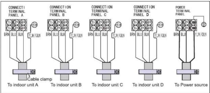
ВНИМАНИЕ!
natural_image
Line drawing of hands installing or adjusting a component on a wall (no text or symbols)natural_image
Diagram of a cylindrical air conditioner unit with airflow arrows indicating airflow direction (no text or symbols)Фиг. А

natural_image
Technical line drawing of a structural component with a mesh grid pattern and an arrow pointing to a feature (no text or symbols)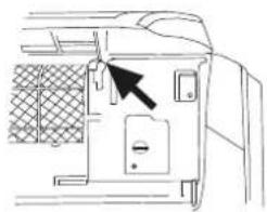
natural_image
Line drawing of a door panel with an arrow pointing to the door handle (no text or symbols present)Фиг. В

Фиг. С

natural_image
Illustration of two hands holding a grid-patterned sheet with scissors, no text or symbols presentФиг. D
natural_image
Illustration of hands using a tool to adjust or install a mechanical component (no text or symbols visible)natural_image
Technical line drawing of an air conditioning unit with cooling fan and internal wiring (no text or symbols)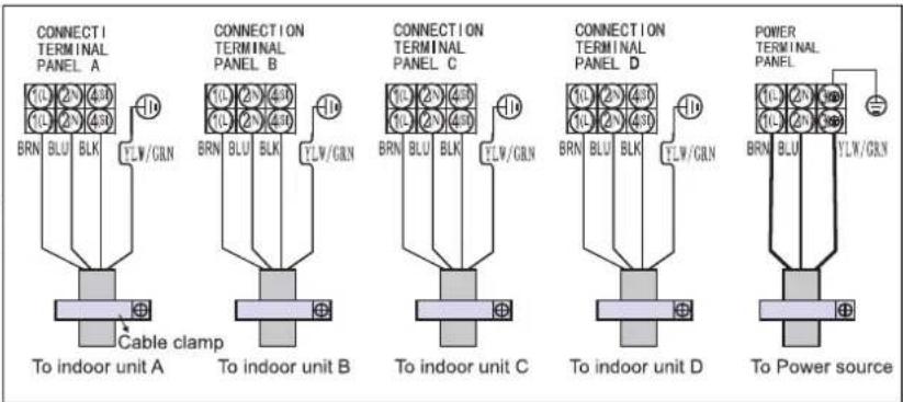
ВНИМАНИЕ:
1. BUTONUL ON/OFF (PORNIT/OPRIT)
2. BUTONUL MODE (MOD)
Precauții
natural_image
Line drawing of hands installing or adjusting a component on a device (no text or symbols)SLEEP 1→SLEEP 2→SLEEP 3→SLEEP 4→NORMAL

natural_image
Diagram of a cylindrical air conditioner with airflow arrows indicating direction (no text or symbols)Fig. A

natural_image
Technical line drawing of a mechanical component with a grid-patterned mesh structure and an arrow pointing to a feature (no text or symbols)
natural_image
Line drawing of a door panel with a black arrow pointing to the door handle (no text or symbols present)Fig. B
natural_image
Diagram of a car air vent with a hand inserting a grid pattern into the vent (no text or symbols)Fig. C

natural_image
Illustration of two hands holding a grid-patterned sheet with a tool, no text or symbols presentFig. D
natural_image
Pure mechanical cross-section diagram without any text, numbers, or symbolsIzolatie termică
natural_image
Diagram showing a pipe with a coiled tube inserted into a cylindrical container, with an arrow pointing to it (no text or symbols present)natural_image
Illustration of hands using a tool to adjust or install a mechanical component (no text or symbols visible)natural_image
Technical line drawing of an air conditioning unit with cooling fan and internal wiring (no text or symbols)