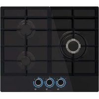
NorCook GH 6032 GBK - Cooker NODOR - Free user manual and instructions
Find the device manual for free NorCook GH 6032 GBK NODOR in PDF.


| Product type | Built-in gas hob |
| Brand | Nodor |
| Model | NorCook GH 6032 GBK |
| Dimensions (W x D x H) | Approx. 60 x 51 x 5 cm |
| Net weight | Approx. 10 kg |
| Gas supply | Natural gas (G20) or propane/butane gas (G30/G31) |
| Supply pressure | 20 mbar for G30, 28 mbar for G30/G31 |
| Number of burners | 4 burners (auxiliary, semi-rapid, rapid, fast) |
| Burner power | 1.00 kW (aux.); 1.75 kW; 2.50 kW; 3.00 kW |
| Ignition | Automatic with battery (type D, 1.5 V) |
| Safety | Thermocouple (thermoelectric safety) |
| Surface material | Tempered glass (ceramic) |
| Connectivity | Remote hood control via radio frequency (RF) |
| Electrical supply required | 230 V / 50 Hz (for ignition and lighting) |
| Gas class | G20 (methane) and G30/G31 (LPG) |
| Injectors included | For G20 and G30/G31 (depending on model) |
| Installation type | Built-in into worktop |
| Maintenance | Clean burners with warm soapy water; ceramic surface with non-abrasive product |
| Included accessories | Sealing gasket, injectors, battery (depending on version) |
| Warranty | Manufacturer's warranty (excluding batteries) |
Frequently Asked Questions - NorCook GH 6032 GBK NODOR
User questions about NorCook GH 6032 GBK NODOR
0 question about this device. Answer the ones you know or ask your own.
Ask a new question about this device
Download the instructions for your Cooker in PDF format for free! Find your manual NorCook GH 6032 GBK - NODOR and take your electronic device back in hand. On this page are published all the documents necessary for the use of your device. NorCook GH 6032 GBK by NODOR.
USER MANUAL NorCook GH 6032 GBK NODOR

NODOR
always innovating
ES Instrucciones para la instalación, el uso, el mantenimiento
DE Anweisungen für die Installation, den Gebrauch, die Wartung
FR Instructions pour l'installation, l'utilisation, l'entretien
EN Installation, use and maintenance instructions
IT Istruzioni per l'installazione, l'uso, la manutenzione
NL Instructies voor installatie, gebruik, onderhoud
PT Instruções para instalação, utilização e manutenção
RU Установка, використння та інструкції по з техническому обслуживанию
تعليمات التركيب والاستخدام و الصيانة AR
NorCook GH N3031 GBK、NorCook GH 6031 GBK、NorCook GH 8631 GBK
Estimado Cliente,
rápido Φ 18 x 24
semi-rápido Φ 14 x 18
auxiliar Φ 12 x 14
pesciera* 18 x 30
Fig. 1
MODELOS QUE INCLUYEN PILAS
Garantía
Fig. 3
G 1/2
ISO 7/1
ISO 228/1 (FR)
Fig. 4
Conexión eléctrica
NorCook GH 8631 GBK NorCook GH 6031 GBK (A)
Nor Cook GH N3031 GBK (B)
(A)
Abb. 6
NorCook GH 8631 GBK NorCook GH 6031 GBK (A)
Nor Cook GH N3031 GBK (B)
(A)
Chère cliente, Cher client,
rapide 18 x 24
semirapide Φ 14 x 18
auxiliaire Φ 12 x 14
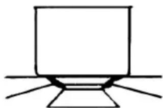
poisson* 18 x 30
Fig. 1
MODÈLES COMPRENANT DES PILES
Garantie
Fig. 2
MODALITÉS D'INSTALLATION
Installation
Fig. 3
Fig. 6
We thank you and congratulate you on your choice.
This new carefully designed product, manufactured with the highest quality materials, has been carefully tested to satisfy all your cooking demands. We would therefore request you to read and follow these easy instructions which will allow you to obtain excellent results right from the start.
May we wish you all the very best with your modern appliance!
THE MANUFACTURER
INDEX
MODELS INCLUDING BATTERIES
Warranty
Package
Installation and efficiency
INSTRUCTIONS FOR USE
Installation
Use
Maintenance
INSTRUCTIONS FOR THE INSTALLATER
Installation
Gas connection
Electrical connection
Injectors characteristics
THIS APPLIANCE IS CONCEIVED FOR DOMESTIC USE ONLY. THE MANUFACTURER SHALL NOT IN ANY WAY BE HELD RESPONSIBLE FOR WHATEVER INJURIES OR DAMAGES ARE CAUSED BY INCORRECT INSTALLATION OR BY UNSUITABLE, WRONG OR ABSURD USE.
INSTRUCTIONS FOR USE
Installation
All the operations concerned with the installation (electrical connection) must be carried out by qualified technicians, in terms with the standards in force, for specific instructions, kindly read the part reserved for the installation technician.
Use
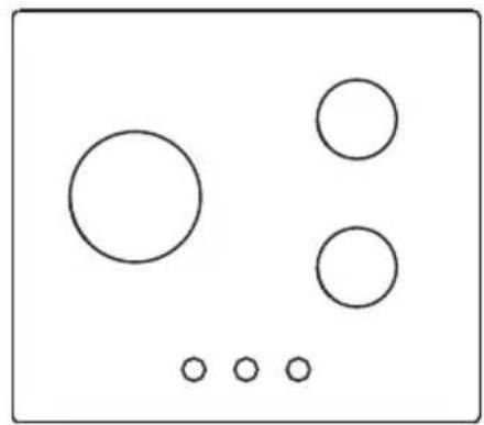
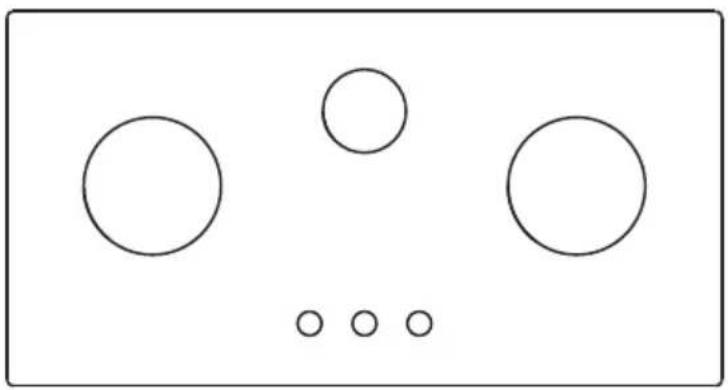
Gas burners (fig. 1).
The ignition of the gas burner is carried out by putting a small flame to the upper part holes of the burner, pressing and rotating the corresponding knob in an anti-clockwise manner, until the maximum position has coincided with the marker. When the gas burner has been turned on, adjust the flame according to need. The minimum position is found at the end of the anti-clockwise rotation direction.
In models with automatic ignition, operate the knob as described above, pressing simultaneously, the corresponding push-button. For models with automatic/simultaneous (with one hand) ignition, it is sufficient to proceed as described above using the corresponding knob. The electric, spark, between the ignition plug and the burner provides the ignition of the burner itself After ignition, immediately release the push-button and adjust the flame according to need.
For models with a thermoelectric safety system, the burner is ignited as in the various cases described above, keeping the knob fully pressed on the maximum position for approximately 3/5 seconds. After releasing the knob, make sure the burner is actually lit.
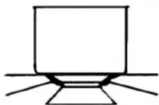
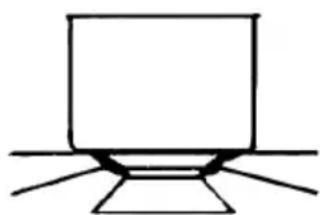
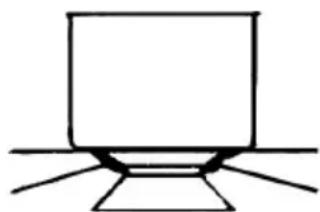
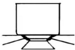
N.B.: - we recommend the use of pots and pans with a diameter matching that of the burner, thus preventing the flame from escaping from the bottom part and surrounding the pot
- do not leave any empty pots or pans on the fire
- do not use any tools for grill-cooking on Crystal hobs.
When cooking is finished, it is also a good norm to close the main gas pipe tap and/or cylinder.
GAS
* with reduction grid
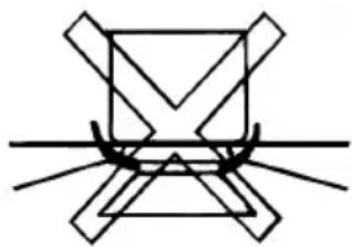
fast Φ 18 x 24
semifast Φ 14 x 18
auxiliary 12 x 14
fish* 18 x 30
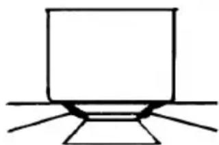
Fig. 1
MODELS INCLUDING BATTERIES
Warranty
Warranty (warranty service) does not include the battery.
The gas hob manufacturer is exempt of any responsibility for the malfunction of batteries.
Package
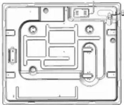
Some models include batteries (D or LR20 or R20S type; 1,5 V) for the autoignition function. Capacity (device) to install the battery located at the bottom back left side of the hob as shown in the picture.
If the battery is not included and should be purchased separately.
Installation and efficiency
Before installing your hob on a tabletop, first insert a battery (checking "+" and "-" into a special device located at the bottom back left side of the hob as shown in the picture.
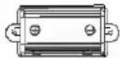
Before final fixation of the hob in a tabletop with special sealer (liner) with adhesive basing (included) make sure autoignition works correctly. In order to do it, push any knob turning it counterclockwise so that its index points at the flame symbol waiting until there are sparks followed by characteristic cracks (clicks).
In case that autoignition doesn't work properly, check if batteries are unloaded and proceed to change it.
If problems aren't solved, call the Customer Service or maintenance.
Maintenance
Gas/Electrical
Prior to any operation, disconnect the appliance from the electrical system.
For long-life to the equipment, a general cleaning operation must take place periodically, bearing in mind the following:
- the glass, steel and/or enamelled parts must be cleaned with suitable non-abrasive or corrosive products (found on the market). A void chlorine-base products (bleach, etc.);
- avoid leaving acid or alkaline substances on the working area (vinegar, salt, lemon juice, etc.).
- the wall baffle and the small covers (mobile parts of the burner) must be washed frequently with boiling water and detergent, taking care to remove every possible encrustation. Dry carefully and check that none of the burner holes is fully or partially clogged;
- the electrical parts are cleaned with a damp cloth and are lightly greased with lubricating oil when still warm.
- the stainless steel grids of the working area, after having been heated, take on a bluish tint which does not deteriorate the quality. To bring colour back to its original state, use a slightly abrasive product.
N.B.: - Cleaning of the taps must be carried out by qualified personnel, who must be consulted in case of any functioning anomaly.
Check periodically the state of conservation of the flexible gas feed pipe. In case of leakage, call immediately the qualified technicians for its replacement.
Maintenance vitroceramic surface
(Fig.-2) First of all remove stray food bits and grease drops from the cooking surface with the special scraper (fig. 2). Then clean the hot area as best as possible with SIDOL, STAHLFIX or other similar products with a papertowel, then rinse again with water and dry with a clean cloth.
Pieces of aluminum foil and plastic material which have inadvertently melted or sugar remains or highly sacchariferous food have to be removed immediately from the hot cooking area with the special scraper (fig. 2). This is to avoid any possible damage to the surface of the top.
Under no circumstances should abrasive sponges or irritating chemical detergents be used such as oven sprays or spot removers.
Do not use steam cleaning appliances to clean the cooking surface.
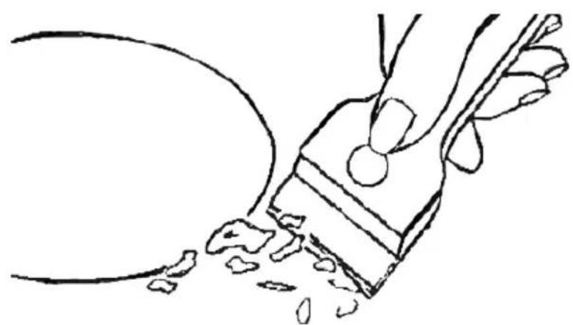
Fig. 2
INSTRUCTIONS FOR THE INSTALLER
Installation
This appliance is not provided with a combustion product discharge. It is recommended that it be installed in sufficiently aerated places, in terms of the laws in force. The quantity of air which is necessary for combustion must not be below 2.0 m3/h for each kW of installed power.
See table of burner power.
Positioning
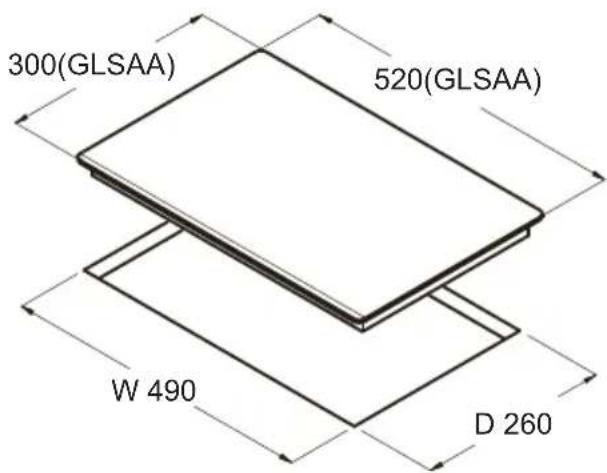
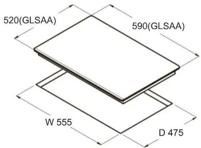
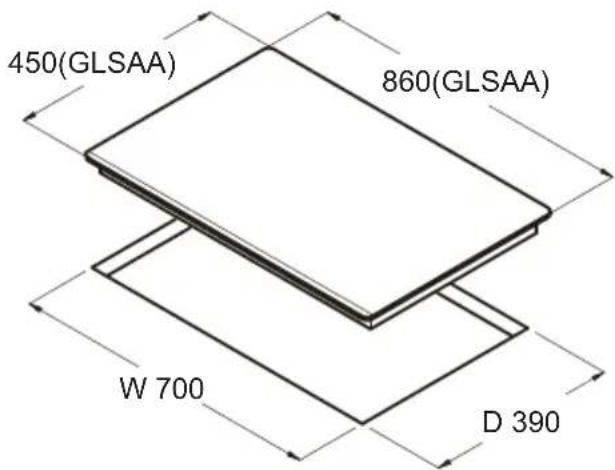
The appliance can be fitted into a working area as illustrated on the corresponding figure. Before positioning the hob, fit the seal around the entire peripnery of the hole cut in the worktop.
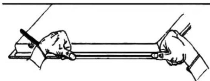
Fig. 3
- that the plant is fitted with an efficient earth connection, following the standards and law provisions in force.
The earth connection is compulsory in terms of the law. Should there be no cable and/or plug on the equipment, use suitable absorption material for the working temperature as well, as indicated on the matrix plate. Under no circumstance must the cable reach a temperature above 50\ °C of the ambient temperature.
Should a direct connection to the network be required, it will be necessary to interpose an omnipolar switch with minimum aperture between the 3 mm. contacts, dimensioned to bear the plate load and it must follow the standards in force (the yellow/green earth cable must not be interrupted by the switch). The plug or omnipolar switch must be easily reached on the installed equipment.
The manufacturers decline any responsibility in the event of non-compliance with what is described above and the accident prevention norms not being respected and followed.
If the mains cable becomes damaged, replace it immediately with a cable or special cable set obtained from the manufacturer or from after sales service.
The use of silicone for the sealing is prohibited. It is only permitted to use the seal provided.
The use of clay pots and heat diffusers is prohibited.
GAS CONNECTION
(Fig. 4) Connect the appliance to the gas cylinder or to the installation according to the prescribed standards in force, and ensure beforehand, that the appliance matches the type of gas available. Otherwise, see “Adaptation to various types of gas”. Furthermore, check that the feed pressure falls within the values described on the table: “Injectors characteristics”.
Rigid/semirigid metal connection
Carry out the connection with fittings and metal pipes (even flexible pipes) so as to obtain counter stress the inner parts of the appliance.
N.B.: - token the installation has been carried out, check the perfect sealing of the entire connection system, by using a soapy solution.
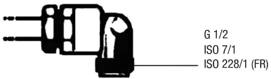
Fig. 4
Electrical connection
(Fig. 5) Prior to carrying out the electricat connection, please ensure that:
- the plant characteristics are such as to follow what is indicated on the matrix plate placed at the bottom of the working area;

Fig. 5
- that the plant is fitted with an efficient earth connection, following the standards and law provisions in force. The earth connection is compulsory in terms of the law. Should there be no cable and/or plug on the equipment, use suitable absorption material for the working temperature as well, as indicated on the matrix plate. Under no circumstance must the cable reach a temperature above 50 °C of the ambient temperature.
Should a direct connection to the network be required, it will be necessary to interpose an omnipolar switch with minimum aperture between the 3 mm. contacts, dimensioned to bear the plate load and it must follow the standards in force (the yellow/green earth cable must not be interrupted by the switch). The plug or omnipolar switch must be easily reached on the installed equipment.
The manufacturers decline any responsibility in the event of non-compliance with what is described above and the accident prevention norms not being respected and followed.
If the mains cable becomes damaged, replace it immediately with a cable or special cable set obtained from the manufacturer or from after sales service.
Adaptation to various types of gas
(Fig. 6) Should the appliance be pre-set for a different type of gas than that available, proceed as follows:
- replace the injectors (Fig. 6) with the corresponding type of gas to be used (see table "Injectors characteristics").
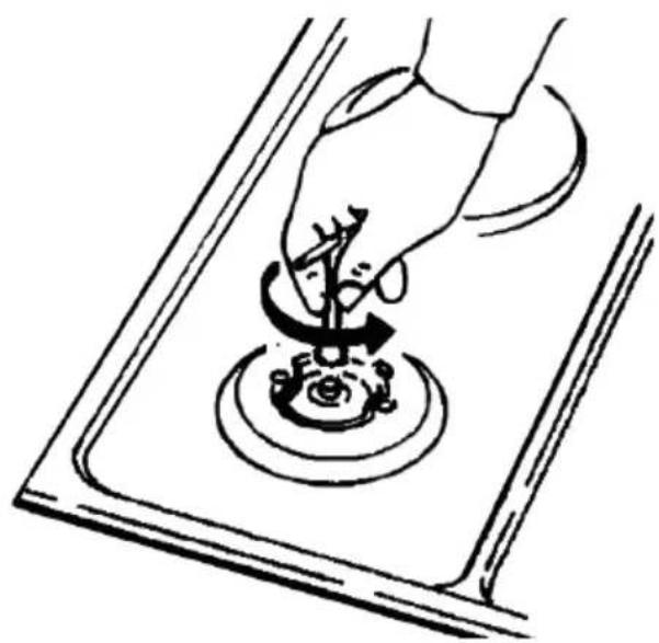
Fig. 6
Regulation of burners
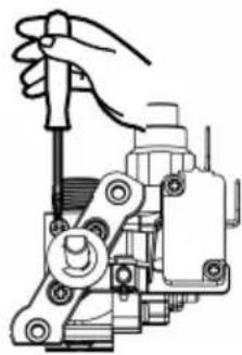
CAUTION: The regulation described can only be carried out with burners that use methane gas and methane/nitrogen blends (where available), and the screw must be fully tightened in a clockwise direction on burners using LPG.
CAUTION: The Minimum position on the burners MUST be adjusted by a qualified gas engineer only.

(A)
- Detach the glass from gas hob.
- Remove the light shade.
- Remove control board.
CAUTION: Cut off the power supply before removing control board.
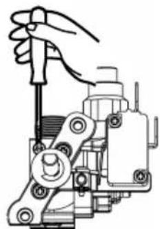
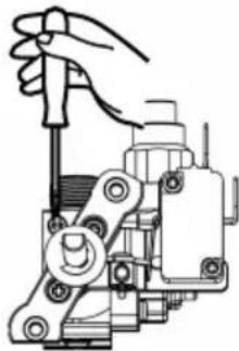
Regulation of the "MINIMUM" position on the burners.
To regulate the minimum position on the burners, follow the procedure below:
- Turn on the burner and turn the knob to its MINIMUM position (small flame).
- Remove the burner knob and turn the fixing screw to the right or left until the flame of the burner is regulated in the most suitable manner to MINIMUM and remains stable.
- Make sure that the flame does not go out when changing the position quickly from MAXIMUM to MINIMUM position.
| (cm)(cm) | ||||
| RRL1L1 | L2L2L3L3L4L4 | |||
| 1166441 | 0107070 | |||
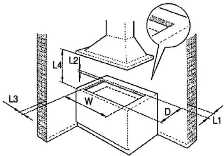
Fig. 8
II2H3+
| INJECTORS CHARACTERISTICS | |||||||
| GAS BURNERS | TYPE | PRESSURE | INJECTORS | CONSUMPTION | THERMAL CAPACITY NOMINAL | ||
| mbar | 1/100mm | g/h | l/h | Kw | Kcal/h | ||
| Auxiliar | G 20 | 20 | 74 | - | 95 | 1.00 | 860 |
| G30/G31 | 28 | 51 | 73 | - | 1.00 | 774 | |
| Semifast | G 20 | 20 | 98 | - | 167 | 1.75 | 1617 |
| G30/G31 | 28 | 69 | 127 | - | 1.75 | 1617 | |
| Fast | G 20 | 20 | 114 | - | 238 | 2,50 | 1720 |
| G30/G31 | 28 | 81 | 182 | 0 | 2,50 | 2064 | |
| Faster | G 20 | 20 | 124 | - | 286 | 3,00 | 2451 |
| G30/G31 | 28 | 88 | 218 | 0 | 3,00 | 2924 | |
Controlling the cooker hood remotely

IMPORTANT: This section is only applicable if you have also purchased a compatible cooker hood with Radio Frequency (RF) capability. Contact the Customer Helpline at the end of this manual for compatible models.
01 Before First Use
This gas hob model and a compatible cooker hood model must be paired by Radio Frequency (RF) before remote control can occur.
When connected the power output of the gas hob will control the extraction rate of the cooker hood.
02 To Set Up Connectivity
- Make sure that the hob and the hood is off.
- Touch the Timer Key and the Light On/Off Key on the hood control panel simultaneously. LED light on the hood control panel will be flashing white.
- Press any of the control knobs down for approximately ten seconds to connect the hob to the hood and the thermocouple will click constantly.
After connection is made, the hood will display "A" in its control panel and the hob will show the RF connectivity icon on the glass to indicate that the hob and hood are paired.

IMPORTANT: The connectivity operation above must be completed within two minutes of turning on the power to the hood. If this is not successful, switch off both the hood and the hob, wait for one minute and attempt the connectivity again.
03 Using The Connectivity Function
The extraction rate of the hood will vary based upon the total power output selected on the hob, as shown in the table. Each hob cooking zone has a maximum rated output of 6.
| Hob levels Sumatory | 6 speeds hood control | 5 speeds hood control | 4 speeds hood control | 3 speeds hood control |
| GAS HOB RF | SPEED WORKING | |||
| 1 to 2 | 1st | 1st | 1st | 1st |
| 3 to 4 | 2nd | 1st | 1st | 1st |
| 5 to 6 | 3rd | 2nd | 2nd | 2nd |
| 7 to 9 | 4th | 3rd | 2nd | 2nd |
| 10 to 12 | 5th | 4th | 3rd | 3rd |
| >12 | 6th | 5th | 4th | 3rd |
If the hood controls are manually overridden when the hob and hood are linked, the hood will operate for five minutes on this manual setting before returning to control by the hob.
To reconnect the hood and hob immediately, press the Timer and Light keys together on the cooker hood.
04 Stopping the connectivity function
- Turning off the gas hob will stop the connectivity with the hood, but this will be restored automatically when the hob is turned on again.
- If the hob is switched off, the hood will continue to operate in its Timer Mode and will step down through the fan speeds automatically.
The motor of the hood will continue for 5 minutes at the current speed and step down for 2 minutes at each level until finally switching off.

Caro Cliente,
rapido Φ 18 x 24
semirapido Φ 14 x 18
ausiliario Φ 12 x 14
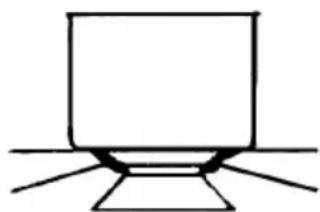
pesciera* 18 x 30
Fig. 1
MODELLI CON PILE INCLUSE
Garanzia
ISTRUZIONI PER L'INSTALLATORE
Installazione
Fig. 3
NorCook GH 8631 GBK NorCook GH 6031 GBK (A)
Nor Cook GH N3031 GBK (B)
(A)
snel Φ 18 x 24
matig snel Φ 14 x 18
sudderpit Φ 12 x 14
vis* 18 x 30
Afb. 1
MODELLEN MET BATTERIJEN
Garantie
INSTRUCTIES VOOR DE INSTALLATEUR
Installatie
rápido Φ 18 x 24
semi-rápido Φ 14 x 18
auxiliar Φ 12 x 14
pesciera* 18 x 30
Fig. 1
MODELOS QUE INCLUEM PILHAS
Garantia
INSTRUÇÕES PARA O INSTALADOR
Instalação
1 صورة
الصيانة
2 4 × 1 8 قطر
SRYEG
1 8 × 1 4 قطر
متوسط
1 4 × 1 2 قطر
عادي
G 1/2
ISO 7/1
ISO 228/1 (FR)
4 صورة
التوصيل الكهربائي

NODOR
always innovating
CNA
group
CATA ELECTRODOMÉSTICOS, S.L.
This page will not be printed
70g双胶纸 A5 单色印刷 骑马钉版
版本号:20230524 V1.4
- NODOR
- ESTIMADO CLIENTE
- MODELOS QUE INCLUYEN PILAS
- GARANTÍA
- CONEXIÓN ELÉCTRICA
- (A)
- CHÈRE CLIENTE, CHER CLIENT
- MODÈLES COMPRENANT DES PILES
- GARANTIE
- MODALITÉS D'INSTALLATION
- INSTALLATION
- THE MANUFACTURER
- INDEX
- MODELS INCLUDING BATTERIES
- INSTRUCTIONS FOR USE
- INSTRUCTIONS FOR THE INSTALLATER
- USE
- WARRANTY
- PACKAGE
- INSTALLATION AND EFFICIENCY
- MAINTENANCE
- GAS/ELECTRICAL
- MAINTENANCE VITROCERAMIC SURFACE
- INSTRUCTIONS FOR THE INSTALLER
- POSITIONING
- GAS CONNECTION
- RIGID/SEMIRIGID METAL CONNECTION
- ELECTRICAL CONNECTION
- ADAPTATION TO VARIOUS TYPES OF GAS
- REGULATION OF BURNERS
- CONTROLLING THE COOKER HOOD REMOTELY
- 01 BEFORE FIRST USE
- 02 TO SET UP CONNECTIVITY
- 03 USING THE CONNECTIVITY FUNCTION
- 04 STOPPING THE CONNECTIVITY FUNCTION
- CARO CLIENTE
- MODELLI CON PILE INCLUSE
- GARANZIA
- ISTRUZIONI PER L'INSTALLATORE
- INSTALLAZIONE
- MODELLEN MET BATTERIJEN
- INSTRUCTIES VOOR DE INSTALLATEUR
- INSTALLATIE
- MODELOS QUE INCLUEM PILHAS
- GARANTIA
- INSTRUÇÕES PARA O INSTALADOR
- INSTALAÇÃO
- ALWAYS INNOVATING
- THIS PAGE WILL NOT BE PRINTED
Brand : NODOR
Model : NorCook GH 6032 GBK
Category : Cooker