
Wireless - Electrostimulation device COMPEX - Free user manual and instructions
Find the device manual for free Wireless COMPEX in PDF.

| Product Type | Electrical Muscle Stimulation and Pain Relief Device |
| Brand | Compex |
| Model | Wireless |
| Number of Channels | 4 independent and individually adjustable channels |
| Pulse Shape | Rectangular, constant current compensated (eliminates DC component) |
| Maximum Intensity | 120 mA |
| Pulse Duration | 50 to 400 µs |
| Pulse Frequency | 1 to 150 Hz |
| Remote Control Battery | Lithium Polymer 3.7 V / ≥ 1500 mAh, rechargeable |
| Module Battery | Lithium Polymer 3.7 V / ≥ 450 mAh, rechargeable |
| Mains Power Supply | Adapter 5 V / 3.5 A (ref. 6490xx) |
| Wireless Connectivity | 2.4 GHz radio frequency, range ≤ 2 m |
| Programs Included | Endurance, Strength, Resistance, Recovery, Massages, TENS, etc. |
| Special Features | mi-SCAN (automatic adaptation), DEMO mode, personalized schedule |
| Kit Contents | Remote control + 4 modules + charging station + adapter + USB cable + electrodes (5×5 cm and 5×10 cm) + guide + carrying case |
| Care and Cleaning | Soft cloth and solvent-free alcohol-based detergent |
| Operating Conditions | Temperature 0 to 40 °C, humidity 30-75%, max altitude 3000 m |
| Storage Conditions | Temperature -20 to 45 °C, max humidity 75% |
| Safety Standards | IEC 60601-1, IEC 60601-1-2, IEC 60601-2-10 |
| Safety and Contraindications | Pacemaker, epilepsy, pregnancy (abdomen), severe circulatory disorders |
Frequently Asked Questions - Wireless COMPEX
User questions about Wireless COMPEX
0 question about this device. Answer the ones you know or ask your own.
Ask a new question about this device
Download the instructions for your Electrostimulation device in PDF format for free! Find your manual Wireless - COMPEX and take your electronic device back in hand. On this page are published all the documents necessary for the use of your device. Wireless by COMPEX.
USER MANUAL Wireless COMPEX
Storage and transportation conditions 4
Use conditions 4
Disposal 4
Standards 4
Patents
Standardized symbols 5
Technical characteristics 5
4. HOW DOES ELECTROSTIMULATION WORK? 6
5. INSTRUCTIONS FOR USE 7
Electrode placement 7
Body positions 7
Adjusting stimulation energies 7
Progression through the levels 7
6. HOW COMPEX WIRELESS WORKS 8
1 Description of the device 8
2 First use: DEMO mode 9
3 Synchronise your remote control 9
4 Getting started with your device 10
4.1 Select Schedule, Objectives, Settings or Programmes menu 10
4.2 Connect the modules to the electrodes 12
4.3 Preparing for your session 12
4.4 Start your session 13
5 Recharging 14
6 Troubleshooting 16
7. OBJECTIVE 17
8. PROGRAMMES 17
1 INTRODUCTION
Please read this manual carefully prior to using your Compex Wireless unit. You are strongly advised to read chapter 2 of this manual. The Compex Wireless is a stimulator intended for muscular training and pain relief. Anyone except for those persons mentioned in chapter 2 "Warnings" can use the Compex Wireless.
2 WARNINGS
No modification or opening of this equipment is allowed!
CONTRAINDICATIONS
• Cardiac stimulator (pacemaker)
- Epilepsy
• Pregnancy (do not use on the abdominal area)
• Serious arterial circulation disorders in lower limbs
• Abdominal or inguinal hernia
OSTEOSYNTHESIS EQUIPMENT
The presence of osteosynthesis equipment (metallic equipment in contact with the bone: pins, screws, plates, prostheses, etc.) is not a contraindication for use. The electrical current of the Compex Wireless is specially designed not to cause damage to osteosynthesis equipment.
Important!
- Do not use Compex Wireless if you have sensitivity problems.
- Never use the Compex for prolonged periods without medical advice.
- Consult your doctor if you want to use the device for rehabilitation purposes.
- Persons unable to express themselves should not use the device.
- Consult your doctor if you are in any doubt whatsoever.
- Read this manual carefully, in particular chapter 8, which provides information concerning the effects and indications of each stimulation programme.
SAFETY MEASURES
- Do not apply stimulation near the area of an implant, such as cochlear implants, pacemakers, electrical or skeletal anchorage implants.
- Do not apply stimulation near metal. Remove jewellery, body piercings, belt buckles or any other removable metallic product or device in the area of stimulation.
- If pregnant or menstruating, do not place electrodes directly over the uterus or connect pairs of electrodes across the abdomen.
- Do not use the Compex Wireless in water or in a humid atmosphere (sauna, hydrotherapy, etc.).
- Do not use the Compex Wireless in an oxygen-rich atmosphere.
- Never carry out an initial stimulation session on a person who is standing. The first five minutes of stimulation must always be performed on a person who is sitting or lying down. In rare instances, very highly strung people may have a vagal reaction. This is of psychological origin and is connected with a fear of the muscle stimulation as well as surprise at seeing one of their muscles contract without their having intentionally contracted it themselves. This vagal reaction produces a feeling of weakness with a tendency towards fainting which slows down the heartrate and decreases blood pressure. If this does occur, all you need to do is stop the stimulation and lie down with your legs raised for the time it takes for the feeling of weakness to disappear (5 to 10 minutes).
- Never allow movement resulting from muscular contraction during a stimulation session. You should always stimulate isometrically; this means that the extremities of the limb in which a muscle is being stimulated must be firmly fixed, so as to prevent any movement resulting from contraction.
- Do not use the Compex Wireless if you are connected to a high-frequency surgical instrument as this could cause skin irritations or burns under the electrodes.
- Do not use the Compex Wireless unit within one metre of short wave or microwave devices as this could alter the current generated by the stimulator. If you have any doubts when using the stimulator in close proximity to another medical device, please contact the device manufacturer or your doctor.
- Do not use the Compex Wireless in areas where unprotected devices are used to emit electromagnetic radiation. Portable communications equipment can interfere with electrical medical equipment.
- During a stimulation session, do not disconnect any modules which are on. Switch them off first.
• Always use the AC adaptor provided by Compex to recharge the device.
• To prevent the risk of electric shock, never use the Compex Wireless unit or the AC adaptor if damaged or open - Disconnect the AC adaptor immediately if there is an abnormal smell or rise in temperature, or if there is smoke coming from the AC adaptor or the device.
• To eliminate the risk of electrocution, never place the charging station in a confined space (carrying case, drawer, etc.) during charging. - Keep the Compex Wireless unit and its accessories out of reach of children. Do not allow any foreign objects (soil, water, metal, etc.) to get into the device or the AC adaptor.
- Sudden temperature changes can cause condensation to build up inside the stimulator. Only use the device once it has reached ambient temperature.
- Do not use the Compex while driving or operating machinery.
- Do not apply stimulation while sleeping.
- Do not use the stimulator at altitudes of over 3,000 metres.
- When the Remote Control is not connected to docking station, the USB connector can only be used for connection to a computer.
PRECAUTIONS WHEN USING THE COMPEX WIRELESS UNIT
• After trauma or a recent operation (less than 6 months prior)
- Muscle atrophy
- Persistent pain
- Need for muscle rehabilitation
NEVER APPLY THE ELECTRODES:
- Near the head
• On the front and sides of the neck. - Contralaterally, i.e. do not use two poles connected to the same channel on opposite sides of the body.
- On or near injuries of any kind (wounds, swelling, burns, irritations, eczema, cancerous lesions etc.).
PRECAUTIONS WHEN USING THE ELECTRODES
- Only use electrodes supplied by Compex. Other electrodes may have electrical properties that are unsuitable for the Compex Wireless unit and may damage it. Caution should always be exercised with current densities greater than 2mA/cm^2 .
• Always turn off the stimulator before moving or removing any electrodes during a session. - Do not immerse the electrodes in water.
- Do not apply solvents of any kind to the electrodes.
- Do not attempt to place electrodes on any part of the body which is not directly visible without assistance.
- For best results, wash and clean the skin of any oil and dry it before attaching the electrodes.
- When attaching the electrodes, please ensure that the entire surface is in contact with the skin.
- For obvious reasons of hygiene, each user must have his/her own set of electrodes. Do not use the same electrodes on different people.
- Never use a set of adhesive electrodes for more than 15 sessions as their bonding power deteriorates over time and optimal contact is very important for both user comfort and stimulation efficacy.
- Some people with very sensitive skin may experience redness under the electrodes after a session. Generally, this redness is completely harmless and disappears after 10 to 20 minutes. However, avoid starting a stimulation session on the same area until the redness is no longer visible.
- Please consult the instructions for use and storage on the electrode packaging.
3 PRESENTATION
EQUIPMENT AND ACCESSORIES
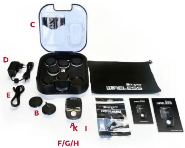
Kit contents:
A. 1 remote control (6522026)
B. 4 stimulation modules (984337)
C. 1 docking station (683121)
D. 1 AC adaptor (649023)
E. 1 USB cable (601163)
F. 2 bags of small electrodes (5x5 cm) (42215)
G. 2 bags of large electrodes (5x10 cm 2snap connections) (42216)
H. 2 bags of large electrodes (5x10 cm 1snap connection) (42222)
1. 1 quick start guide (M321318)
J. 1 travel pouch (680029)
K. 1 warning leaflet (M307815)
WARRANTY
See the enclosed leaflet.
MAINTENANCE
Clean with a soft cloth and an alcohol based, solvent-free cleaning product. Use only a minimum amount of liquid when cleaning the unit. Do not disassemble the remote control, modules, docking station or AC adaptor as all these contain high voltage components that could cause electric shock. This may only be done by persons or repair services authorised by Compex. Your Compex Wireless device does not require calibration. If your device contains parts that seem worn or defective, please contact your nearest Compex customer service centre to bring it up to standard.
STORAGE AND TRANSPORTATION CONDITIONS
The unit must be stored and transported in accordance with the following conditions:
Temperature: -20^ C to 45^ C
Maximum relative humidity: 75 %
Atmospheric pressure: 700 hPa to 1060 hPa
USE CONDITIONS
Temperature: 0°C to 40°C
Relative humidity: 30 % to 75 %
Atmospheric pressure: 700 hPa to 1060 hPa
Do not use in areas where there is a risk of explosion.
DISPOSAL
Batteries must be disposed of in compliance with national regulatory requirements. Any products bearing the WEEE marking (a crossed-out rubbish bin) must be separated from ordinary household waste and sent to special collection facilities for recycling.
STANDARDS
To guarantee your safety, the Compex Wireless device has been designed and manufactured in compliance with the requirements of the European Medical Device Directive 93/42/EEC as amended.
The Compex Wireless unit also complies with the general safety standard for electromedical equipment, EN 60601-1. It also complies with the electromagnetic compatibility standard, EN 60601-1-2 and the standard on particular safety requirements for nerve and muscle stimulators, EN 60601-2-10.
Current international standards require that a warning be given concerning the application of electrodes to the thorax (increased risk of cardiac fibrillation).
The Compex Wireless also complies with Directive 2002/96/EEC on waste, electrical and electronic equipment (WEEE).
PATENTS
The Compex Wireless incorporates several innovations with patents pending or already issued.
STANDARDIZED SYMBOLS


Caution / Follow the user manual or operating instructions.

mpex Wireless unit is a class II device with internal electric power and type BF applied parts.

e and address of the manufacturer and manufacturing date. 20xx

address of the authorised representative in the European Community.

vice must be separated from ordinary household waste and sent to special collection facilities for g and recovery.

'Off button is a multi-function button.

izing radiation

ay from sunlight


TECHNICAL CHARACTERISTICS
A General information
Remote control battery: Lithium Polymer (LiPo) rechargeable 3.7[V] / ≥ 1500[mAh].
Module battery: Lithium Polymer (LiPo) rechargeable 3.7[V] / ≥ 450[mAh].
AC adaptor: Only AC adaptor 5[V] / 3.5[A] bearing the part number 6490xx can be used to recharge the Compex Wireless unit.
B Neurostimulation
All electrical specifications are given for an impedance of 500-1000 Ohm per channel.
Channels: Four independent and individually adjustable channels, electrically insulated from each other.
Pulse shape: Constant rectangular current with pulse compensation to eliminate any direct current component to prevent residual polarisation at skin level.
Maximum pulse intensity: 120 mA.
Pulse intensity increments: Manual adjustment of stimulation intensity from 0 to 999 (energy) in minimum increments of 0.25 mA.
Pulse width: 50 to 400 μs.
Maximum electrical charge per pulse: 96 microcoulombs (2 x 48 μC, compensated).
Standard pulse ramp-up time: 3 μs (20%-80% of maximum current).
Pulse frequency: 1 to 150 Hz.
CRF data
Frequency band of emission and reception: 2.4[GHz] ISM (2.4-2.4835GHz)
Modulation type and frequency characteristics: GFSK, +/-320[kHz] deviation
Effective radiated power: 4.4 [dBm]
Compex Wireless may be interfered by other equipment, even if that other equipment complies with CISPR EMISSION requirements.
D Information related to electromagnetic compatibility (EMC)
The Compex Wireless unit is designed to be used in typical domestic environments approved in accordance with EMC safety standard EN 60601-1-2.
This device emits very low levels in the radio frequency (RF) interval and is therefore not liable to cause any interference with nearby electronic equipment (radios, computers, telephones etc.).
The Compex Wireless unit is designed to withstand foreseeable disturbances originating from electrostatic discharges; mains supply magnetic fields or radio frequency transmitters.
Despite this, it is not possible to guarantee that the stimulator will not be affected by strong RF (radio frequency) fields emitting from other sources.
4 HOW DOES ELECTROSTIMULATION WORK?
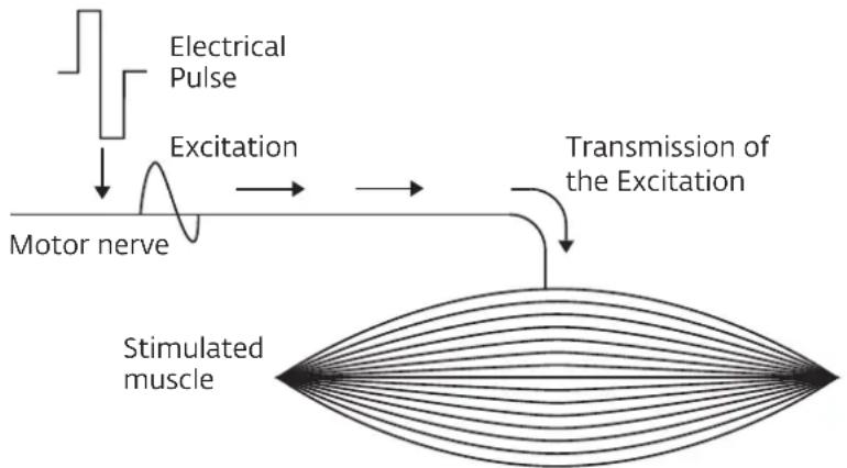
The principle of electrostimulation is to stimulate nerve fibres by means of electrical impulses transmitted by electrodes. The electrical pulses generated by Compex stimulators are high quality pulses - offering safety, comfort and efficiency - which can stimulate different types of nerve fibres:
- The motor nerves, to stimulate a muscular response. The quantity and the benefits obtained depend on the stimulation parameters and this is known as electro-muscular stimulation (EMS).
- Certain types of sensitive nerve fibres to obtain analgesic or pain-relieving effects.
1. Motor nerve stimulation (EMS)
During voluntary activity, the order for muscular work comes from the brain, which sends a command to the nerve fibres in the form of an electrical signal. This signal is then transmitted to the muscle fibres, which contract. The principle of electrostimulation accurately reproduces the process observed during a voluntary contraction. The stimulator sends an electrical current impulse to the nerve fibres, exciting them. This excitation is then transmitted to the muscular fibres causing a basic mechanical response (= muscle twitch). The latter constitutes the basic requirement for muscular contraction. This muscular response is completely identical to muscular work controlled by the brain. In other words, the muscle cannot distinguish whether the command comes from the brain or from the stimulator.
The parameters of the Compex programmes (number of impulses per second, contraction time, rest time, total programme time) subject the muscles to different types of work, depending on the muscle fibres. In fact, different types of muscle fibres may be distinguished according to their respective contraction speed: slow, intermediate and fast fibres. The fast fibres will obviously predominate in a sprinter, while a marathon runner will have more slow fibres. With a good knowledge of human physiology and a perfect mastery of the stimulation parameters of the various programmes, muscular work can be directed very precisely towards the desired goal (muscular reinforcement, increased blood flow, firming up, etc.).
flowchart
graph TD
    A["Electrical Pulse"] --> B["Excitation"]
    B --> C["Motor nerve"]
    C --> D["Transmission of the Excitation"]
    D --> E["Stimulated muscle"]
Elementary mechanical reponse - twitch
2. Stimulation of the sensory nerves
The electrical impulses can also excite the sensory nerve fibres to obtain an analgesic or pain relieving effect. The stimulation of the tactile sensory nerve fibres blocks the transmission of pain by the nervous system. The stimulation of another type of sensory fibres creates an increase in the production of endorphins and, therefore, a reduction in pain. With pain relief programmes, electrostimulation can be used to treat localised acute or chronic pain as well as muscle pain.
Caution: Do not use pain relief programmes for prolonged periods without medical advice.
ELECTROSTIMULATION BENEFITS
Electrostimulation is a very effective way to make your muscles work:
- With significant improvement in different muscular qualities
• Without cardiovascular or mental fatigue
- With limited stress placed on the joints and tendons. Electrostimulation thus allows a greater quantity of work to be done by the muscles compared with voluntary activity.
To be effective, this work must involve the greatest possible number of muscle fibres and the number of fibres that are working depends on the stimulation energy. It is therefore necessary to work with the maximum tolerable energy. This aspect of stimulation is controlled by the user. The higher the stimulation energy, the greater the number of muscle fibres that are working and, therefore, the more significant the progress achieved. To maximise your results, Compex recommends that you complement your electrostimulation sessions with other efforts, such as:
- Regular exercise
• Proper and healthy nutrition
• A balanced lifestyle
5 INSTRUCTIONS FOR USE
The instructions for use presented in this chapter should be considered to be general guidelines.
ELECTRODE PLACEMENT
For optimal results, use the recommended electrode positions.
A different electrode must be connected to each module.
Note: It is possible and normal to have an electrode arrangement that leaves one electrode connection free.
For programmes which induce strong muscle (tetanic) contractions, it is important to place the electrode attached to the pod with the on/off button on the motor point of the muscle. It is crucial to choose the right size electrodes (large or small) and correctly position these on the muscle group you want to stimulate to ensure the efficacy of the treatment. Therefore, you should always use the size of electrode shown in the pictures. Always follow the placement directions shown in the illustrations unless you have other specific medical instructions. Where necessary, look for the best possible position by slowly moving the positive electrode over the muscle until you find the point that will produce the best contraction or the greatest comfort.
Note: Approximate placing of the electrodes makes for a less efficacious session, but is still without risk.
Compex disclaims all responsibility for consequences arising from electrodes placed in other positions.
Electrode placement illustrations can be found in the Objective or Programme selector on the website at www.compexwireless.com or right on the remote control under the icon when you select an Objective or a programme.
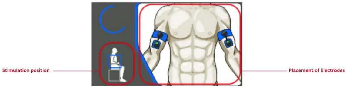
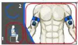
BODY POSITIONS
This position will vary depending on the position of the electrodes, the muscle group you wish to stimulate, and the programme you are using. For programmes inducing powerful muscular contractions (tetanic contractions), the muscle should always be stimulated in an isometric fashion. You should therefore fix the extremities of your limbs securely. This way, you provide maximum resistance to the movement and prevent any shortening of the muscle during the contraction, which could result in cramps and stiffness after your session. For example, when stimulating the quadriceps, the user should be in a seated position with resistance around the ankle area to prevent extension of the knees. For other types of programme which do induce powerful muscle contractions, but rather merely muscle twitches, position yourself as shown in the illustration, making sure that you are comfortable.
ADJUSTING STIMULATION ENERGIES
In a stimulated muscle, the number of recruited fibres depends on the stimulation energy. For programmes inducing powerful muscle contractions (tetanic contractions), you must therefore use maximum stimulation energies (up to 999), always at the limit of what you can endure, in order to call up the maximum number of fibres.
For programmes only inducing muscle twitches, you should progressively increase the stimulation energies until you obtain clearly visible muscle twitches.
PROGRESSION THROUGH THE LEVELS
In general, it is not advisable to go through the different levels too quickly with the intention of reaching level 3 as fast as possible. In fact, the different levels correspond to progress in electrostimulation training. The simplest and most usual procedure is to start with level 1 and raise the selected level when moving to a new stimulation cycle. At the end of a cycle, you may either start a new cycle at the next level up or do some maintenance at the rate of 1 session a week at the last level used.
6 HOW COMPEX WIRELESS WORKS
It is highly recommended that you read the contraindications and safety measures described at the beginning of this manual in chapter 2 prior to using your device.
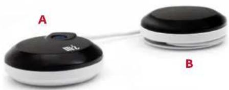
1 DESCRIPTION OF THE DEVICE
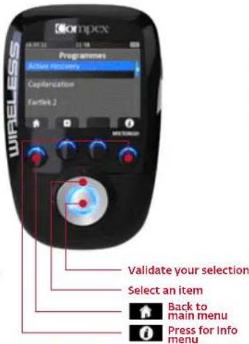
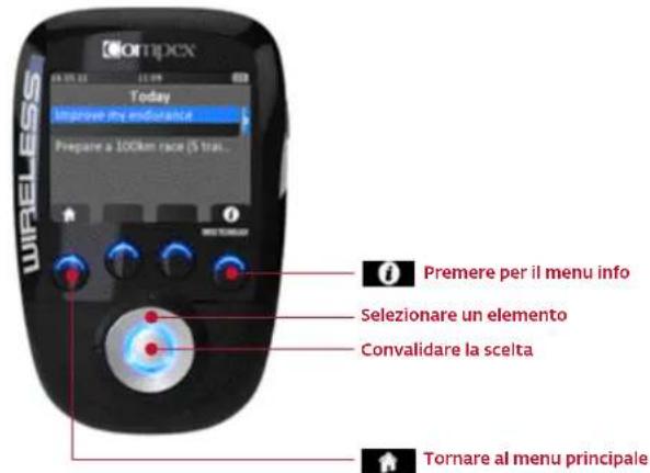
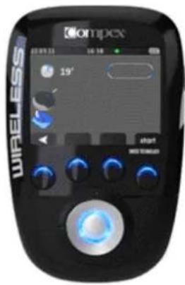
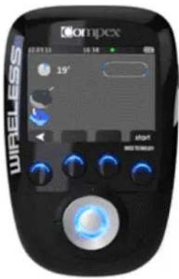
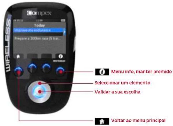
REMOTE CONTROL
A On/Off button (press briefly to switch on but press and hold longer than 2 seconds to switch off)
B 4 multi-function buttons:
- Functions associated with the icons shown on the screen (e.g. info, main menu, electrode placement, etc.)
- Selection of stimulation channel to increase or decrease stimulation energy level
C Multi-directional pad (up-down-left-right) to select items
D Validation button
E Port for USB cable or docking station connector

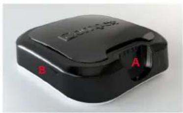
MODULE
A On/Off button (press briefly to switch on but press and hold longer than 2 seconds to switch off)
• LED blinking green: ready for use
• LED blinking yellow: stimulating
B Groove to wind up the cable
natural_image
Two connected devices labeled A and B, one with a black circular top and the other with a white circular top (no visible text or symbols on the devices themselves)DOCKING STATION
A Connector for charging the remote control
B Notch for opening the top of the docking station
C Slot for positioning the modules to be recharged
D Socket for the AC adaptor
natural_image
Black electronic device with labeled ports A and B, no visible text or symbols on body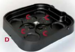
natural_image
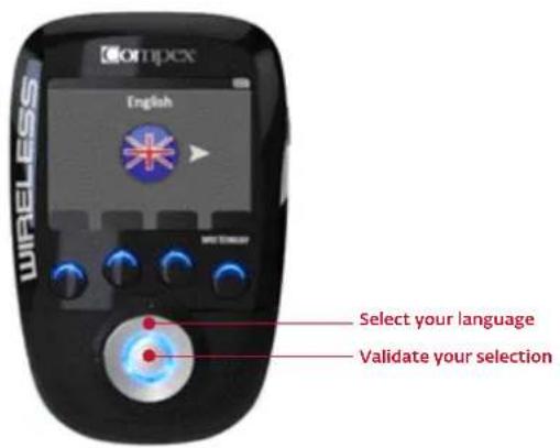
Black plastic tray with red 'C' marks on one side, labeled 'D' in bottom-left corner (no other text or symbols)2 FIRST USE: DEMO MODE
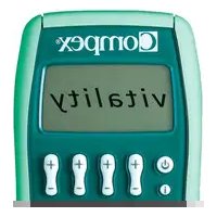
SELECT THE LANGUAGE
DEMO mode is available until you have paired your device with your account. DEMO mode only gives you access to certain programmes and not to all the possibilities of the Compex Wireless (empty calendar and no objectives).
Compex recommends that you visit www.compexwireless.com to create your own account which will allow you to download training plans and programmes, follow your progress on your calendar or create your own objectives.
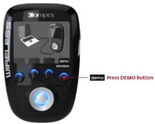
DEMO MODE
3 SYNCHRONISE YOUR REMOTE CONTROL
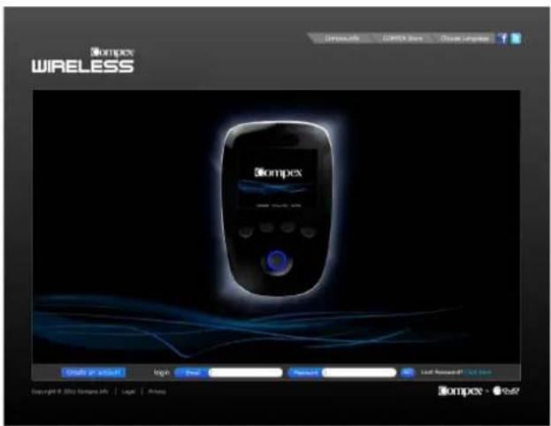
CREATE YOUR PERSONAL ACCOUNT
In order to take advantage of all of the possibilities of the Compex Wireless (download training plans, create your own objectives, follow your progress, download new programmes, etc.), you should first create your personal account at www.compexwireless.com. Follow the instructions provided on the website.
If you don't want to create an account, you can still use the product in DEMO mode (see item 2:First use: DEMO mode)
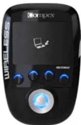
PAIR YOUR REMOTE CONTROL WITH YOUR ACCOUNT
Once your personal account has been created, you can log into it and pair your remote control. To do so, please follow the instructions displayed on the website www.compexwireless.com
A Log into your account
B Download and install the software on your computer
C Click on the "Pair your remote" button and enter the serial number of your remote
D Connect the remote control to your computer using the USB cable provided and press the channel 4 button (the one with the icon 📋). A validation code will appear on the screen of the remote
E Type in the code in the designated field on the website
F Your remote control is now paired with your account
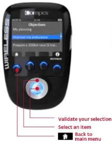
4 GETTING STARTED WITH YOUR DEVICE
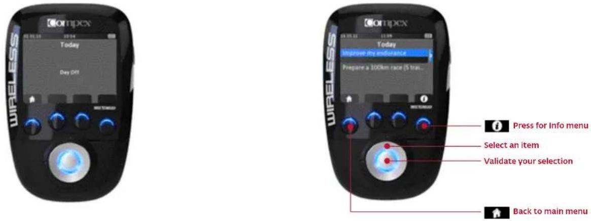
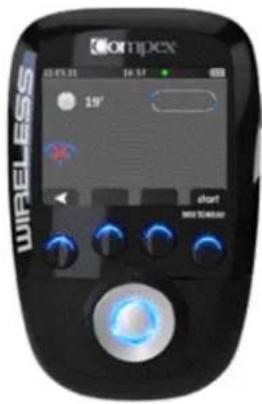
Once you have synchronised your remote control with your account and switched on your device, the first screen you see shows the tasks scheduled for that day.
It is highly likely that you will see "day off" displayed on the screen, but if you had already scheduled Objectives, you would have seen some scheduled tasks displayed. From this screen you can begin your session (see Select an objective or a programme)
4.1 SELECT SCHEDULE, OBJECTIVES, SETTINGS OR PROGRAMMES MENU
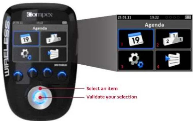

1. SCHEDULE
Here you will find your calendar with the sessions you have already completed and those you still need to do.
• A green rectangle below the day means that you have done what was planned
• An orange rectangle below the day means you have not done what was planned in the past
- A grey rectangle below the day means that you have planned an activity in the future
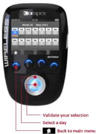
Select a day to view the details for it. From there you can begin your session (see Select an objective or a programme).

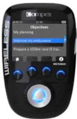
2. OBJECTIVE
Here you will find the objectives you have downloaded from the website.
To learn how to navigate in this menu, see Select an objective or a programme.

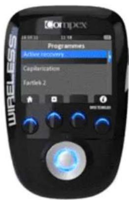
4. PROGRAMMES
The programmes menu contains the programmes you have downloaded from the website.
To learn how to navigate in this menu, see Select an objective or a programme.
Please note: Only a limited number of programmes are installed in DEMO mode. Once you have paired your remote control with your account, you will be able to modify this list by adding or removing programmes.

3. SETTINGS
In the settings menu you can set several parameters such as backlight, volume, language, etc.

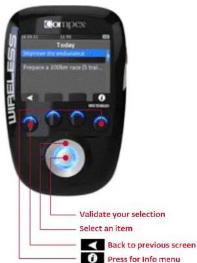
SELECT AN OBJECTIVE OR A PROGRAMME
The steps for selecting an objective or a programme are similar.
SELECT AN OBJECTIVE
SELECT A PROGRAMME
WHEN AN OBJECTIVE IS SELECTED YOU CAN SEE THE DETAILS OF ALL THE SESSIONS IT COMPRISES.
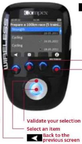

See the electrode placement and body position associated with your objective and selected task. For programmes, you will be able to view all the possible electrode placements. For objectives, you will see what placement to use. To scroll through the illustrations, use the up/down button on the multi-directional pad.
You can now place the electrodes on your body connect the modules to
Connect the modules to
Press for Info menu
Please note: For voluntary sessions (cycling in this example), you have to validate the session yourself by pressing the button under the icon √
*1. Body position
- Electrode placement
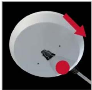
4.2 CONNECT THE MODULES TO THE ELECTRODES
Stick the electrodes on your skin. Electrodes are attached from the side. Slide the module along the electrode snap until you hear a click. Please note: Markings tell you which way to insert: the On/Off button on the main pod and a little vertical line on the shellthe other pod.
To disconnect the module from the electrode, just do the reverse.
natural_image
Diagram showing a red arrow pointing to a circular object with a black dot, no text or symbols present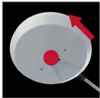
natural_image
Diagram of a device with a red circular component and a white bowl, showing an arrow pointing to it (no text or symbols present)4.3 PREPARING FOR YOUR SESSION
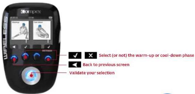
WARM-UP AND COOL-DOWN
This screen is not available for all programmes.
You can choose to do the warm-up phase before starting the session and the cool-down phase at the end of the stimulation session.
Please note: Compex recommends that you keep the warm-up phase, unless you have already done a voluntary warmup, and the cool-down phase.
4.4 START YOUR SESSION
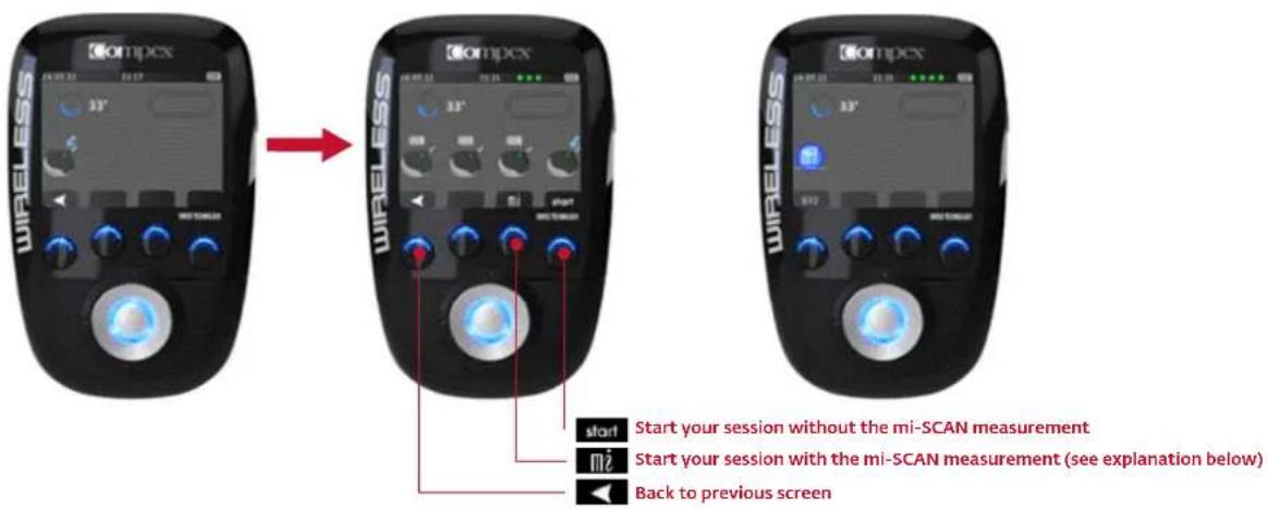
SWITCH ON THE MODULES BEFORE STARTING THE STIMULATION SESSION
Before initiating the stimulation and mi-SCAN measurement, you have to turn on the modules one after another by pressing their On/Off buttons. Once the 1st module is detected by the remote control, you can switch on the 2nd module and so on up to the 4th module. If you only want to use two modules for your session, just press the START button after the second module is detected.
Please note: For a session which is optimally adapted to your muscles, Compex recommends that you always perform an mi-SCAN measurement before starting a stimulation session.
BEGINNING OF THE STIMULATION SESSION: MI-SCAN MEASUREMENT
This feature adapts the electrostimulation session to each individual user's physiology. Just before starting your stimulation session, mi-SCAN probes the chosen muscle group and automatically adjusts the stimulator parameters to the excitability of this area of the body. It is a truly personalized measurement. In order to ensure that your session is as effective and comfortable as possible, it is highly recommended that you perform the mi-SCAN at each session.
This function is implemented at the start of the programme by a short sequence during which measurements are taken. You should remain completely still and be perfectly relaxed throughout the measurement test. Once the test has been completed, the programme can start.
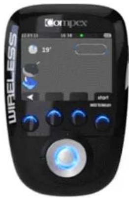
DISPLAY EXPLANATIONS
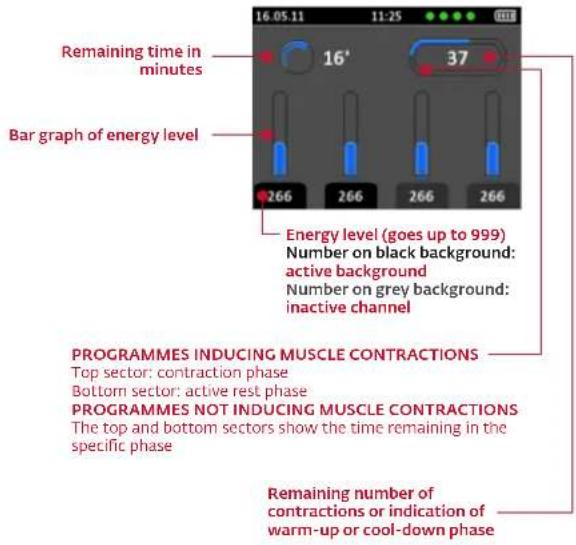
DURING THE STIMULATION SESSION
Stimulation always starts off at 000 (+++).
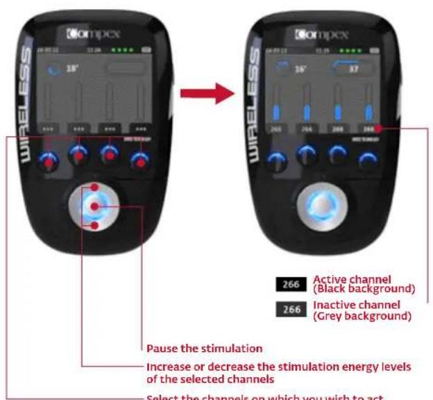
- Select the channels on which you wish to act. When a channel is active, the LED of the button gives off a solid blue light. Please note: by default, all channels are active at the start of a session. Please note: pressing the button for a given channel for more than 1 second activates that channel and deactivates all the others.
N.B.: Active rest phase stimulation energies are automatically set at 50% of contraction energies. These can be modified during the rest phase. Once modified, they will be totally independent of the contraction energies.
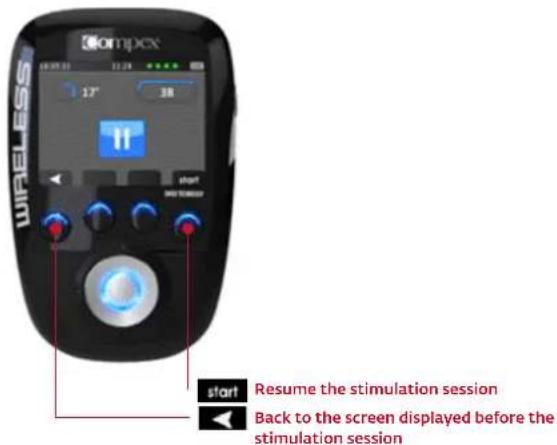
PAUSE MODE
You can pause the device by pressing the centre button or the On/Off button on one of the modules during the stimulation.
Please note: The session will resume at 80 % of the energy levels that were being used prior to the interruption.
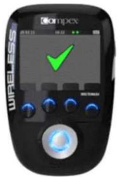
END OF SESSION
At the end of the session, a screen with a check mark comes up. Press any button to return to the main menu. To switch off the device, just press and hold the On/Off button on the remote control for more than 2 seconds. This will also switch off all the modules.
5 RECHARGING
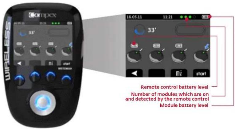
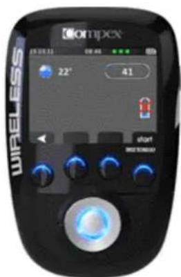
BATTERY LEVEL
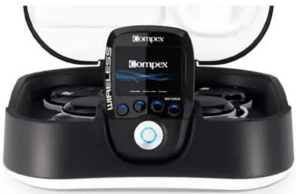
The battery level of each module is shown when you switch them on before starting your stimulation session. The battery level of the remote is always visible in the upper right corner. The little green circles indicate how many modules are switched on and can be detected by the remote control.
CONNECT THE DOCKING STATION
Connect the AC adaptor supplied with your device to the docking station then plug it into a socket. Compex strongly advises you to fully charge the remote and module batteries before using them for the first time as this will improve their performance and life span.
CHARGING THE MODULES AND THE REMOTE CONTROL
At the end of your stimulation session, it is highly recommended that you store the remote control and the modules in the docking station in order to recharge them.
natural_image
Exterior view of a wireless medical device with Ompex logo and control panel (no readable text or symbols beyond branding)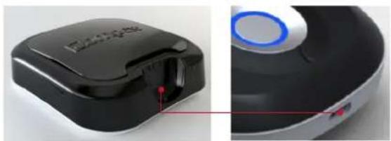
natural_image
Close-up of a black and white electronic device with a blue circular button, shown from side to top (no visible text or symbols)
natural_image
Simple 3D-rendered object with a dark rectangular body and a small protrusion, no text or symbols visible.THIS SCREEN COMES UP AS SOON AS THE REMOTE CONTROL IS CONNECTED TO THE DOCKING STATION.
Then, place the modules in the spaces provided.
natural_image
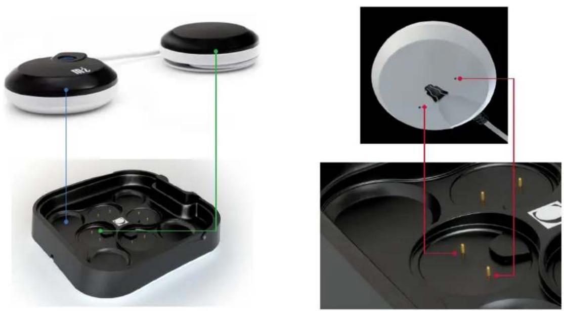
Product diagram showing a smartwatch with labeled components and internal views of a device (no text or symbols present)To do this, place the pod without the On/Off button (the green one in the illustration) in the slot indicated in green and the other pod in the blue slot. Do the same for the other modules.
The pod without the On/Off button (the green one) has to be inserted in the small connector. A magnet should help you in positioning the pod as well as the groove of the pod. When it is placed correctly you should hear a click.
When you place a module on the docking station, a red circle will appear to indicate that charging is in progress. The module is still charging as long as the red circle is visible. As soon as this disappears, the module is completely charged and ready for use.
N.B.: If the module is charged when you place it on the docking no red circle will appear.
As soon as the modules and the remote control are fully charged the actual time is displayed.

6 TROUBLESHOOTING
ELECTRODE FAULT

The remote control shows the symbol of an electrode and a disconnected module on the channel where the problem is detected (in this example, channel 1).
- Check whether the electrodes are properly connected to the module.
- Check whether the electrodes are old, worn, and/or the contact is bad: If you suspect this may be the cause, try using new electrodes.
MODULE OUT OF RANGE
The remote control shows the out of range symbol on the channel where the problem has been detected (in this example, channel 1).
- Check to see whether the module and the remote are less than 2 metres apart.
• Make sure that you are not in a remote location with any obstacles which can reflect the signal of the remote control.
• Make sure that you are in a place where the signal of the remote control can be reflected.
SYNCHRONISATION PROBLEM
If the synchronisation process has been interrupted or if for any reason you cannot synchronise (remote disconnected, power failure, etc.), the remote control may, display this screen.
- Reconnect the remote control to your PC and re-start the synchronisation process by pushing the button for channel 4 (the one with the icon).
THE MODULE'S BATTERY HAS RUN OUT
During stimulation, a module's battery may run out. If this happens, the symbol of an empty battery is displayed on the channel where the problem has been detected (in this example, channel 4).
• You can stop the stimulation and recharge the module with the empty battery.
- You can set aside the module with the empty battery and continue your stimulation session without it.
MODULE LED BEHAVIOUR
The LED blinks green and red alternately: the module is out of range or not recognised by the remote control.
- Make sure the remote control is switched on.
- Check to see whether the module and the remote are less than 2 metres apart.
THE LED IS ALWAYS RED
• Make sure the module is charged.
- Try to re-start the remote control and the modules.
- If despite this the LED is still red, contact an official Compex customer service centre.
STIMULATION IS NOT PRODUCING THE USUAL SENSATION
- Check that all the settings are correct and ensure the electrodes are positioned properly.
- Change the positioning of the electrodes slightly.
THE STIMULATION CAUSES DISCOMFORT
• The electrodes are losing their bonding strength and are no longer providing suitable contact with the skin.
• The electrodes are worn and need to be replaced.
- Change the positioning of the electrodes slightly.
THE UNIT IS NOT WORKING
- Make sure the remote control and the modules are switched on.
- Try to re-start the remote control and the modules.
- If despite this the unit still does not work, contact an official Compex service centre.
7 OBJECTIVE
There is no objective available in DEMO mode on the Compex Wireless. To download objectives you should go to www.compexwireless.com.
Examples of objectives available:
• Prepare for a marathon
• Prepare for a half-marathon
• Prepare for a cycling race
- Increase your strength
• Treat your lower back pain
• Prevent twisted ankles
...
8 PROGRAMMES
The Compex Wireless is set up with the following programmes. Once you have created an account at www.compexwireless.com and synchronised your remote control you will be able to download new programmes.
Please note: Programmes that induce muscle contractions such as Endurance, Resistance, Strength, etc. are offered with 3 different levels. To learn how to use these levels, please see chapter 5. Instructions for use.
| PROGRAMMES EFFECTS | USES | |
| Capillarization Very marked increase in blood flowDevelopment of capillaries | In the period before competition, for those participating in endurance or resistance sportsTo improve endurance in those whose fitness level is not high | |
| Toning massage Activation of blood circulationRecovery of muscular contractile propertiesInvigorating effect | To prepare the muscles in an ideal manner before an unusual/one-time physical activity | |
| Endurance Improved absorption of oxygen by the stimulated musclesImproved performance for endurance sports | For athletes who wish to improve their performance in long-duration sporting events | |
| Resistance Improved lactic capacity of musclesImproved performance for conscious resistance sports | For athletes who wish to increase their capacity to obtain intense and prolonged effort | |
| Strength Increased maximum strengthIncreased rate of muscular contraction | For athletes practising a discipline that requires strength and speed | |
| Explosive strength Increases the speed at which the level of strength is attainedImproved efficiency of explosive actions (jumping, sprinting, etc.) | For athletes practising a discipline in which explosive strength is an important factor in performance | |
| Hypertrophy Increased muscle volumeIncreased muscle resistance | For athletes who wish to increase their muscle mass | |
| Fartlek Training and preparation of muscles for all kinds of muscular work (endurance, resistance, strength, explosive strength) through different working sequences | At the beginning of the season to "re-set" the muscles after a rest period and before more intensive and specific trainingDuring the season for those who do not have any preferences for a single kind of performance and prefer to exercise their muscles with different work-out methods | |
| Active recovery Marked increase in blood flowAccelerates the elimination of waste from the muscular contractionEndorphinic effectRelaxing effect | To improve and accelerate the muscle recovery after an intensive exerciseTo be used during the first 3 hours after each session of intensive training or after a competition | |
| Relaxing massage Decreased muscular tensionDrainage of the toxins responsible for the exaggerated increase of muscular toneEffect of well-being and relaxation | To eliminate uncomfortable or painful sensations, following an exaggerated increase of muscular tone | |
| Anti-stress massage Improvement of tissue vascularisationDecreased muscular tension associated with stressReturn to calm | To restore a sensation of well-being after stressful situations | |
| Heavy legs Increased venous returnIncreased supply of oxygen to musclesDrop in muscular tensionElimination of tendency to have cramp | To restore a sensation of well-being after stressful situations | |
| Modulated TENS Blocks | transmission of pain by the nervous system To remove the | feeling of heaviness in the legs arising in unusual situations (standing for long periods, heat, hormonal imbalance linked to the menstrual cycle, etc.) |
| Endorphinic Analgesic action | through the release of endorphins Increased blood flow | All acute or chronic localized pain |
| Decontracture Reduced muscle tension | muscular tension Relaxing effect | To combat chronic muscular pain |
| Disuse atrophy Reactivation | on of the trophic action of muscle fibres damaged during atrophy | To combat recent and localized muscular pain |
| Muscle growth Increased | diameter and capacity of muscle fibres damaged during under-activity or inactivity imposed by some kind of pathological problem Restoration of muscle volume | Treatment to combat any reduction of muscle volume: As a result of trauma necessitating immobilisationAccompanying degenerative lesions to joints |
| Reinforcement Increase the strength of a muscle previously atrophied Increase the strength of a muscle affected by a pathological process | After a period of using the Disuse atrophy treatment, as soon as the muscle shows signs of a slight recovery of volume or toneUntil the virtually complete restoration of muscle volume | |
| Muscle building Improved muscle trophismBalanced increase of muscular tone and volume | At the end of rehabilitation, when the muscle has regained normal muscle volumeFrom the onset of rehabilitation for non-atrophied muscles | |
| Toning To tone the musc | es To be used to begin with in order to tone up and | prepare the muscles before more intensive firming work |
| Firming To regain muscle | firmness and restore the support function of the muscles | To be used as the main treatment for muscle firming |
| Shaping To define and sculpt the body when the muscles are already firm | To be used when the firming phase is finished | |
- INTRODUCTION 20
- AVERTISSEMENT 20
Contre-indications
20
MAINTENANCE
natural_image
Two connected devices labeled A and B, one black with a white 'MLZ' on its side (no additional text or symbols visible)STATION DE CHARGE
natural_image
Black and white photo of a black electronic device with labeled ports A and B (no visible text or symbols on body)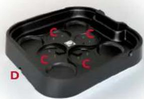
natural_image
Black plastic tray with red 'C' and letter 'X' markings, labeled 'D' in bottom-left corner (no other text or symbols)APPAIRER VOTRE TÉLÉCOMMANDE À VOTRE COMPTE

4. PROGRAMMES

3. PARAMÈTRES
natural_image
Close-up of a white bowl with a red arrow pointing to a dark object inside, no visible text or symbols.natural_image
Top-down view of a white bowl with a red circular object inside, and a red arrow pointing upward (no text or symbols)4.3 PRÉPARER VOTRE SÉANCE
ÉCHAUFFEMENT ET RELAXATION
5 RECHARGE
NIVEAU DE BATTERIE
natural_image
Exterior view of a wireless oxygen sensor device with black casing and digital display (no visible text or symbols)
natural_image
Close-up of a black and white electronic device with a blue circular button, shown from front and side views (no text or symbols visible)
natural_image
Simple 3D-rendered object with a dark rectangular body and a small protrusion, no text or symbols visible.DÈS QUE LA TÉLÉCOMMANDE EST BRANCHÉE À LA STATION DE CHARGE CET ÉCRAN APPARAÎT.
natural_image
Two electronic devices with black and white enclosures, one showing a green indicator light (no text or symbols visible)
natural_image
Top-down view of a white bowl with red annotation lines pointing to a small object, bottom-down view of a black tray with yellow pins (no text or symbols)OSTEOSYNTHESEMATERIAL
WARTUNG
natural_image
Two electronic devices labeled A and B, one with a black cover and connected to a white base (no visible text or symbols on the devices themselves)LADESTATION
natural_image
Black and white photo of a device with labeled ports A and B (no visible text or symbols beyond labels)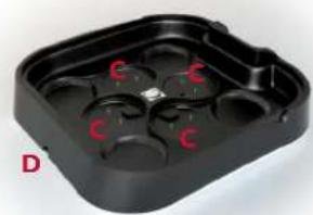
natural_image
Black plastic tray with red 'C' marks on one side, labeled 'D' in bottom-left corner (no other text or symbols)2 ERSTE BENUTZUNG: DEMO-MODUS
AUSWAHL IHRER SPRACHE
KOPPELN IHRER FERNBEDIENUNG MIT IHREM KONTO

4. PROGRAMME
natural_image
Close-up of a white bowl with a red arrow pointing to a small dark object inside, against a black background (no text or symbols)natural_image
Close-up of a white bowl with a red circular object inside, and a red arrow pointing upward (no text or symbols)natural_image
Front view of a wireless oxygenizer device with a digital display and control buttons (no visible text or symbols on the device body)
natural_image
Close-up of a black and white electronic device with a blue circular button, showing internal components and a red indicator light (no text or symbols visible)
natural_image
Simple 3D-rendered object resembling a container or mold, no text or symbols visiblenatural_image
Two electronic devices with green measurement lines highlighting internal components (no text or symbols visible)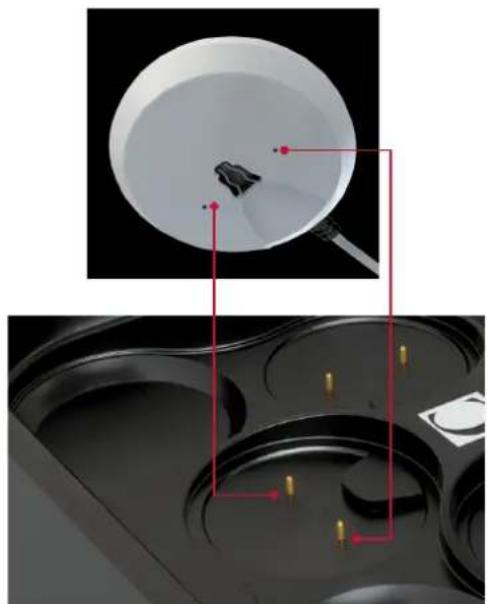
natural_image
Top-down view of a white bowl with red annotation lines pointing to a small object, bottom-down view of a black tray with yellow markers (no text or symbols)MANUTENZIONE
PROGRESSIONE NEI LIVELLI
natural_image
Two black and white electronic devices labeled A and B, connected by a cable (no visible text or symbols on the devices themselves)STAZIONE DI CARICA
natural_image
Black and white photo of a black electronic device with labeled ports A and B (no visible text or symbols on body)
natural_image
Black plastic tray with red 'C' marks, labeled 'D' in bottom-left corner (no other text or symbols)2 PRIMO UTILIZZO: MODALITÀ DEMO

4. PROGRAMMI
natural_image
Close-up of a white bowl with a red arrow pointing to a small dark object inside, against a black background (no text or symbols)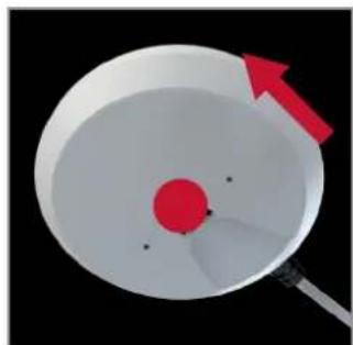
natural_image
Close-up of a white bowl with a red circular object and a red arrow pointing to it, against a black background (no text or symbols)

natural_image
Exterior view of a wireless medical device with Ompex branding and control panel (no readable text or symbols beyond branding)
natural_image
Close-up of a black and white electronic device with a blue circular button, showing internal components and a red indicator line (no text or symbols visible)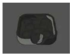
natural_image
Simple 3D-rendered object with a dark rectangular body and a small protrusion, no text or symbols visible.natural_image
Two black electronic devices with green indicator lights placed on their sides, one connected to a white terminal (no visible text or symbols)
natural_image
Top-down view of a white bowl with red annotation lines pointing to a small object, bottom-down view of a black tray with yellow pins (no text or symbols)MANTENIMIENTO
natural_image
Two electronic devices labeled A and B, each with a black circular body and a white connector (no visible text or symbols on the devices themselves)ESTACIÓN DE CARGA
natural_image
Black and white electronic device with labeled ports A and B (no visible text or symbols on body)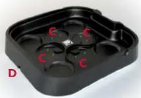
natural_image
Black plastic tray with four circular indentations and red 'C' marks, labeled 'D' in corner (no text or symbols on tray itself)2 PRIMER USO: MODO DEMO
SELECCIONE SU IDIOMA

4. PROGRAMAS
natural_image
Close-up of a white circular object with a red arrow pointing to a small dark object, no visible text or symbols.
natural_image
3D illustration of a red circular object inside a white bowl with a pointer, against a black background (no text or symbols)natural_image
Exterior view of a black wireless earbuds with a digital display showing Ompex branding (no text or symbols on the device itself)
natural_image
Close-up of a black and white electronic device with a blue circular button, shown from side to top (no visible text or symbols)
natural_image
Simple 3D-rendered object with a dark rectangular body and a small protrusion, no text or symbols visible.natural_image
Two connected devices with labeled ports and internal compartments, no visible text or symbols
natural_image
Top-down view of a white bowl with red annotation lines pointing to a small object, bottom-down view of a black tray with yellow pins (no text or symbols)6 PROBLEMAS Y SOLUCIONES
FALLO DE LOS ELECTRODOS
UNDERHÅLL
FÖRDELAR MED ELEKTROSTIMULERING
E
ELEKTRODANSLUTNING
natural_image
Two connected devices labeled A and B, one with a black circular body and the other a rounded body (no visible text or symbols beyond labels)LADDNINGSSTATION
natural_image
Black and white electronic device with labeled ports A and B (no visible text or symbols beyond labels)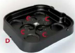
natural_image
Black plastic tray with four red circular buttons labeled 'C', no text or symbols presentSYNKRONISERA DIN STIMULATOR

4. PROGRAM

3. INSTÄLLNINGAR
natural_image
Diagram showing a red arrow pointing to a circular object with a dark irregular shape inside, against a black background (no text or symbols)natural_image
Close-up of a white bowl with a red circular object and a red arrow pointing upward (no text or symbols)4.3 FÖRBERED FÖR STIMULERING
UPPVÄRMNING OCH AVSLAPPNING
5 UPPLADDNING
BATTERINIVÅ
natural_image
Exterior view of a wireless smart device with Ompex branding and control panel (no readable text or symbols beyond branding)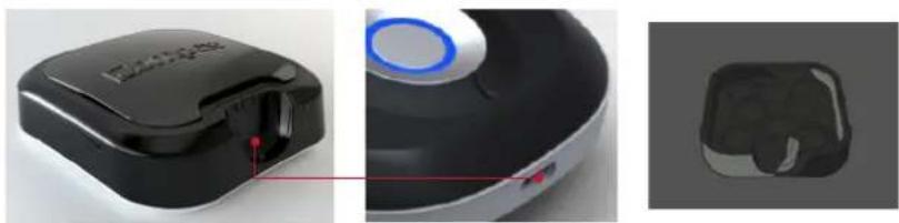
natural_image
Three-panel image showing a black and white device with a red indicator light, alongside a 3D rendered model of a virtual reality headset (no text or symbols visible)SÄ SNART STIMULATORN ANSLUTS TILL LADDNINGSSTATIONEN VISAS DENNA DISPLAY.
natural_image
Two connected devices with green indicator lights, one showing a black sensor module and the other a white display case (no text or symbols visible)
natural_image
Top-down view of a white bowl with red annotation lines pointing to a small object, bottom-down view of a black tray with yellow markers (no text or symbols)6 FELSÖKNING
ELEKTRODFEL

ELEKTRODANSLUTNINGARNAS LYSDIOD
-
INLEIDING 110
-
WAARSCHUWING 110
Contra-indicaties 110 Veiligheidsmaatregelen 110
- BESCHRIJVING 112
OSTEOSYNTHESEMATERIAAL
ONDERHOUD
6 WERKING VAN HET APPARAAT
1 SCHRIJVING VAN HET APPARAAT
AFSTANDSBEDIENING
MODULE
natural_image
Two connected devices labeled A and B, one with a black circular top and the other a white circular base (no visible text or symbols on the devices themselves)LAADSTATION
natural_image
Black and white photo of a black fitness device with labeled ports A and B (no visible text or symbols beyond labels)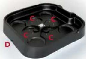
natural_image
Black plastic enclosure with red circular cutouts and 'C' labels, no readable text or symbols2 EERSTE GEBRUIK: DEMO-MODUS
SELECTEER DE TAAL

4. PROGRAMMA'S

3. PARAMETERS
natural_image
Illustration of a bowl with a red arrow pointing to a small object inside, no text or symbols presentnatural_image
Top-down view of a white dome-shaped object with a red circular center and a red arrow pointing upward (no text or symbols)4.3 UW SESSIE VOORBEREIDEN
OPWARMEN EN ONTSPAN NEN
natural_image
Exterior view of a black and white wireless earbuds device with a digital display showing 'Ompex' branding (no text or symbols on the device itself)
natural_image
Close-up of a black and white electronic device with a blue circular button, shown from two angles (no text or symbols visible)
natural_image
Simple 3D-rendered object resembling a container or button, no text or symbols visibleZODRA DE AFSTANDSBEDIENING IS AANGESLOTEN OP HET LAADSTATION VERSCHIJNT DIT SCHERM.
natural_image
Exterior view of a smart home control device with two circular devices and a black plastic case (no visible text or symbols)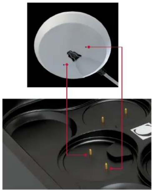
natural_image
Top-down view of a white bowl with red annotation lines pointing to a small object, bottom-down view of a black tray with yellow pins (no text or symbols)6 PROBLEMEN EN OPLOSSINGEN
STORING VAN ELEKTRODEN
GARANTIA
flowchart
graph TD
    A["Electrical Pulse"] --> B["Excitation"]
    B --> C["Motor nerve"]
    C --> D["Transmission of the Excitation"]
    D --> E["Stimulated muscle"]
Elementary mechanical reponse - twitch
natural_image
Two black-and-white electronic devices labeled A and B, connected by a cable (no visible text or symbols beyond labels)ESTAÇÃO DE CARGA
natural_image
Black and white electronic device with labeled ports A and B (no visible text or symbols beyond labels)
natural_image
Black plastic tray with red 'C' marks, no visible text or symbolsEMPARELHAR O SEU TELECOMANDO Â SUA CONTA

4. PROGRAMAS
natural_image
Diagram showing a red arrow pointing to a circular object with a dark irregular shape inside, against a black background (no text or symbols)
natural_image
Diagram of a red sphere inside a white bowl with a red arrow pointing upward (no text or symbols)natural_image
Exterior view of a wireless earbuds device with Ompex brand logo and control buttons (no readable text beyond branding)
natural_image
Close-up of a black and white smart device with a blue circular button, alongside a 3D rendered model (no text or symbols visible)natural_image
Two black electronic devices with green indicator lights and labeled ports, shown from front and side views (no text or symbols on the devices themselves)
natural_image
Top-down view of a white bowl with red annotation lines pointing to a small object, bottom-down view of a black tray with yellow pins (no text or symbols)6 PROBLEMAS E SOLUÇÕES
DEFEITO DE ELÉCTRODOS
The Compex Wireless stimulator needs special precautions regarding EMC and needs to be installed and put into service according to the EMC information provided.
Portable and mobile RF communications equipment can affect the Compex Wireless stimulator.
The use of Accessories, transducers, and cables other than those specified by the manufacturer, may result in increased Emissions or decreased Immunity of the Compex Wireless stimulator.
The Wireless stimulator should not be used adjacent to or stacked with other equipment and if adjacent or stacked use is necessary, the Compex Wireless stimulator should be observed to verify normal operation in the configuration in which it will be used.
| GUIDANCE AND MANUFACTURER'S DECLARATION – ELECTROMAGNETIC EMISSIONS | ||
| The Compex Wireless stimulator is intended for use in the electromagnetic environment specified below. The customer or the user of the Compex Wireless stimulator should assure that it is used in such an environment. | ||
| EMISSION TESTS COMPLIANCE ELECTROMAGNETIC ENVIRONMENT – GUIDANCE | ||
| Radiated Emissions CISPR 11 | Group 1 | The Compex Wireless uses RF energy only for its internal function. Therefore, its RF emissions are very low and are not likely to cause any interference in nearby electronic equipment. |
| Conducted Emissions CISPR 11 | Class B | The Compex Wireless is suitable for use in all establishments, including domestic establishments and those directly connected to the public low-voltage power supply network that supplies buildings used for domestic purposes. |
| Harmonic emissions IEC 61000-3-2 | Class A | |
| Voltage fluctuations IEC 61000-3-3 | Complies | |
| GUIDANCE AND MANUFACTURER'S DECLARATION - ELECTROMAGNETIC EMISSIONS | |||
| The Wireless stimulator is intended for use in the electromagnetic environment specified below. The customer or the user of the Wireless stimulator should assure that it is used in such an environment. | |||
| IMMUNITY TEST IEC 60601 | TEST LEVEL | COMPLIANCE LEVEL ELECTROMAGNETICENVIRONMENT - GUIDANCE | |
| Electrostatic discharge (ESD)IEC 61000-4-2 | ±6kV contact±8kV air | ±6kV contact±8kV air | Floors should be wood, concrete or ceramic tile. If floors are covered with synthetic material, the relative humidity should be at least 30%. |
| Electrical fast transient/burstIEC 61000-4-4 | ±2kV for powersupply lines±1kV forinput/output lines | ±2kV (power lines)Not Applicable (I/O lines) | Mains power quality should be that of a typical commercial or hospital environment. |
| SurgeIEC 61000-4-5 | ±1kV Line to Line(or Neutral)±2kV line(s) to earth | ±1kV Line to LineNot Applicable(Line to Earth) | Mains power quality should be that of a typical commercial or hospital environment. |
| Voltage dips, short interruptions and voltage variations on power supply input linesIEC 61000-4-11 a | <5% UT (>95% dip in UT) for 0,5cycle40% UT (60% dip in UT) for 5cycles70% UT (30% dip in UT) for 25cycles<5% UT (>95% dip in UT) for 5 sec | <5% UT (>95% dip in UT) for 0,5cycle40% UT (60% dip in UT) for 5cycles70% UT (30% dip in UT) for 25cycles<5% UT (>95% dip in UT) for 5 sec | Mains power quality should be that of a typical commercial or hospital environment. If the user of the Compex Wireless stimulator requires continued operation during power mains interruptions, it is recommended that the Compex Wireless stimulator be powered from an uninterrupted power supply or a battery. |
| Power frequency (50/60Hz)magnetic fieldIEC 61000-4-8 | 3 A/m 3 A/m Power frequency magnetic fields | should be at levels characteristic of a typical location in a typical commercial or hospital environment. | |
| ^aU_T is the a.c mains voltage prior to application of the test level. | |||
| GUIDANCE AND MANUFACTURER'S DECLARATION - ELECTROMAGNETIC IMMUNITY | |||
| The Compex Wireless stimulator is intended for use in the electromagnetic environment specified below. The customer or the user of the Compex Wireless stimulator should assure that it is used in such an environment. | |||
| IMMUNITY TEST IEC 60601 | TEST LEVEL | COMPLIANCE LEVEL | ELECTROMAGNETIC ENVIRONMENT - GUIDANCE |
| Conducted RFIEC 61000-4-6 | 3 Vrms150 kHz to 80 MHz | 3Vrms | Portable and mobile RF communications equipment should be used no closer to any part of the Compex Wireless stimulator, including cables, than the recommended separation distance calculated from the equation applicable to the frequency of the transmitter. |
| Radiated RIFEC 61000-4-3 | 3 V/m1.4 GHz to 2,7 GHz10 V/m26MHz to 1GHz | 3V/m10V/m | Recommended separation distanced = 1.2 √Pd = 1.2 √P 80 MHz to 800 MHzd = 2.3 √P 800 MHz to 2,5 GHzWhere P is the maximum output power rating of the transmitter in watts (W) according to the transmitter manufacturer and d is the recommended separation distance in metres (m).Field strengths from fixed RF transmitters, as determined by an electromagnetic site surveya, should be less than the compliance level in each frequency rangeb.Interference may occur in the vicinity of equipment marked with the following symbol: |
| NOTE 1 At 80 MHz and 800 MHz, the higher frequency range applies.NOTE 2 These guidelines may not apply in all situations. Electromagnetic propagation is affected by absorption and reflection from structures, objects and people. | |||
| ^a Field strengths from fixed transmitters, such as base stations for radio (cellular/cordless) telephones and land mobile radios, amateur radio, AM and FM radio broadcast and TV broadcast cannot be predicted theoretically with accuracy. To assess the electromagnetic environment due to fixed RF transmitters, an electromagnetic site survey should be considered. If the measured field strength in the location in which the Compex Wireless stimulator is used exceeds the applicable RF compliance level above, the Compex Wireless stimulator should be observed to verify normal operation. If abnormal performance is observed, additional measures may be necessary, such as reorienting or relocating the Compex Wireless stimulator. ^b Over the frequency range 150 kHz to 80 MHz, field strengths should be less than 3 V/m. | |||
| RECOMMENDED SEPARATION DISTANCES BETWEEN PORTABLE ANDMOBILE RF COMMUNICATIONS EQUIPMENT AND THE COMPEX WIRELESS STIMULATOR | |||
| The Compex Wireless stimulator is intended for use in an electromagnetic environment in which radiated RF disturbances are controlled. The customer or the user of the Compex Wireless stimulator can help prevent electromagnetic interference by maintaining a minimum distance between portable and mobile RF communications equipment (transmitters) and the Compex Wireless stimulator as recommended below, according to the maximum output power of the communications equipment. | |||
| Rated maximum output power of transmitter W | Separation distance according to frequency of transmitter m | ||
| 150 kHz to 80 MHzd = 1.2 √P | 80 MHz to 800 MHzd = 1.2 √P | 800 MHz to 2.5 GHzd = 2.3 √P | |
| 0,01 | 0,12 | 0,12 | 0,23 |
| 0,1 0,38 0,38 0,73 | |||
| 11,2 1,2 2,3 | |||
| 10 3,8 3,8 7,3 | |||
| 100 12 12 23 | |||
| For transmitters rated at a maximum output power not listed above, the recommended separation distance d in meters (m) can be estimated using the equation applicable to the frequency of the transmitter, where P is the maximum output power rating of the transmitter in watts (W) according to the transmitter manufacturer.NOTE 1 At 80 MHz and 800 MHz, the separation distance for the higher frequency range applies.NOTE 2 These guidelines may not apply in all situations. Electromagnetic propagation is affected by absorption and reflection from structures, objects and people. | |||


- HOW DOES ELECTROSTIMULATION WORK? 6
- INSTRUCTIONS FOR USE 7
- HOW COMPEX WIRELESS WORKS 8
- OBJECTIVE 17
- PROGRAMMES 17
- INTRODUCTION
- WARNINGS
- CONTRAINDICATIONS
- OSTEOSYNTHESIS EQUIPMENT
- Important!
- SAFETY MEASURES
- PRECAUTIONS WHEN USING THE COMPEX WIRELESS UNIT
- NEVER APPLY THE ELECTRODES:
- PRECAUTIONS WHEN USING THE ELECTRODES
- PRESENTATION
- EQUIPMENT AND ACCESSORIES
- WARRANTY
- MAINTENANCE
- STORAGE AND TRANSPORTATION CONDITIONS
- USE CONDITIONS
- DISPOSAL
- STANDARDS
- PATENTS
- STANDARDIZED SYMBOLS
- TECHNICAL CHARACTERISTICS
- A General information
- B Neurostimulation
- CRF data
- D Information related to electromagnetic compatibility (EMC)
- HOW DOES ELECTROSTIMULATION WORK?
- Motor nerve stimulation (EMS)
- Stimulation of the sensory nerves
- Caution: Do not use pain relief programmes for prolonged periods without medical advice.
- ELECTROSTIMULATION BENEFITS
- INSTRUCTIONS FOR USE
- ELECTRODE PLACEMENT
- BODY POSITIONS
- ADJUSTING STIMULATION ENERGIES
- PROGRESSION THROUGH THE LEVELS
- HOW COMPEX WIRELESS WORKS
- DESCRIPTION OF THE DEVICE
- REMOTE CONTROL
- MODULE
- DOCKING STATION
- FIRST USE: DEMO MODE
- SELECT THE LANGUAGE
- SYNCHRONISE YOUR REMOTE CONTROL
- CREATE YOUR PERSONAL ACCOUNT
- PAIR YOUR REMOTE CONTROL WITH YOUR ACCOUNT
- GETTING STARTED WITH YOUR DEVICE
- OBJECTIVE
- PROGRAMMES
- SETTINGS
- SELECT AN OBJECTIVE OR A PROGRAMME
- CONNECT THE MODULES TO THE ELECTRODES
- PREPARING FOR YOUR SESSION
- WARM-UP AND COOL-DOWN
- START YOUR SESSION
- SWITCH ON THE MODULES BEFORE STARTING THE STIMULATION SESSION
- BEGINNING OF THE STIMULATION SESSION: MI-SCAN MEASUREMENT
- PAUSE MODE
- END OF SESSION
- RECHARGING
- BATTERY LEVEL
- CONNECT THE DOCKING STATION
- CHARGING THE MODULES AND THE REMOTE CONTROL
- TROUBLESHOOTING
- ELECTRODE FAULT
- MODULE OUT OF RANGE
- SYNCHRONISATION PROBLEM
- THE MODULE'S BATTERY HAS RUN OUT
- MODULE LED BEHAVIOUR
- THE LED IS ALWAYS RED
- STIMULATION IS NOT PRODUCING THE USUAL SENSATION
- THE STIMULATION CAUSES DISCOMFORT
- THE UNIT IS NOT WORKING
- OBJECTIVE
- PROGRAMMES
- STATION DE CHARGE
- APPAIRER VOTRE TÉLÉCOMMANDE À VOTRE COMPTE
- PARAMÈTRES
- PRÉPARER VOTRE SÉANCE
- ÉCHAUFFEMENT ET RELAXATION
- RECHARGE
- NIVEAU DE BATTERIE
- OSTEOSYNTHESEMATERIAL
- WARTUNG
- LADESTATION
- ERSTE BENUTZUNG: DEMO-MODUS
- AUSWAHL IHRER SPRACHE
- KOPPELN IHRER FERNBEDIENUNG MIT IHREM KONTO
- PROGRAMME
- MANUTENZIONE
- PROGRESSIONE NEI LIVELLI
- STAZIONE DI CARICA
- PRIMO UTILIZZO: MODALITÀ DEMO
- MANTENIMIENTO
- ESTACIÓN DE CARGA
- PRIMER USO: MODO DEMO
- SELECCIONE SU IDIOMA
- PROGRAMAS
- PROBLEMAS Y SOLUCIONES
- FALLO DE LOS ELECTRODOS
- UNDERHÅLL
- FÖRDELAR MED ELEKTROSTIMULERING
- ELEKTRODANSLUTNING
- LADDNINGSSTATION
- SYNKRONISERA DIN STIMULATOR
- PROGRAM
- INSTÄLLNINGAR
- FÖRBERED FÖR STIMULERING
- UPPVÄRMNING OCH AVSLAPPNING
- UPPLADDNING
- BATTERINIVÅ
- FELSÖKNING
- ELEKTRODFEL
- ELEKTRODANSLUTNINGARNAS LYSDIOD
- OSTEOSYNTHESEMATERIAAL
- ONDERHOUD
- WERKING VAN HET APPARAAT
- SCHRIJVING VAN HET APPARAAT
- AFSTANDSBEDIENING
- LAADSTATION
- EERSTE GEBRUIK: DEMO-MODUS
- SELECTEER DE TAAL
- PROGRAMMA'S
- PARAMETERS
- UW SESSIE VOORBEREIDEN
- OPWARMEN EN ONTSPAN NEN
- PROBLEMEN EN OPLOSSINGEN
- STORING VAN ELEKTRODEN
- GARANTIA
- ESTAÇÃO DE CARGA
- EMPARELHAR O SEU TELECOMANDO Â SUA CONTA
- PROBLEMAS E SOLUÇÕES
- DEFEITO DE ELÉCTRODOS
Brand : COMPEX
Model : Wireless
Category : Electrostimulation device