DXKH180E - Heating DEWALT - Free user manual and instructions
Find the device manual for free DXKH180E DEWALT in PDF.

| Product Type | Diesel forced-air heater |
| Model | DXKH180E |
| Brand | DeWalt |
| Dimensions (L x W x H) | 1120 mm x 480 mm x 745 mm |
| Weight | 30 kg |
| Power supply | 230 V, 50 Hz, 1~, 1.28 A |
| Heat output | 53 kW |
| Fuel consumption | 5.27 L/h |
| Tank capacity | 56.8 L |
| Max. outlet temperature | 704 °C |
| Air flow rate | 15.5 m³/min |
| Motor | 230 V, 50 Hz, 300 W, 2800 rpm, 9 µF |
| Ignition | Direct spark, interrupted ignition |
| Fuel type | Heating oil (diesel) according to EN 267 |
| Pump pressure | 55 kPa |
| Nozzle size | 1.1 mm |
| Required ventilation | 0.19 m² opening at floor level and 0.19 m² at ceiling level leading outdoors |
| Minimum clearances | Outlet: 250 cm; sides, top, rear: 91.4 cm |
| Safety features | Solid-state control, limit switch, CAD cell, safety shutdown |
| Routine maintenance | Cleaning of air and fuel filters, tank purging, checking connections |
| Repairability | Spare parts available (nozzle, CAD cell, power supply, etc.) |
| Warranty | 2 years |
| Certification | EN-13842:2004, CE 0197/20 |
Frequently Asked Questions - DXKH180E DEWALT
User questions about DXKH180E DEWALT
0 question about this device. Answer the ones you know or ask your own.
Ask a new question about this device
Download the instructions for your Heating in PDF format for free! Find your manual DXKH180E - DEWALT and take your electronic device back in hand. On this page are published all the documents necessary for the use of your device. DXKH180E by DEWALT.
USER MANUAL DXKH180E DEWALT
If you have questions or comments, contact us.
www.DEWALT.com
INSTRUCTION MANUAL
DEWALT®
LANGUAGES INCLUDED: ENGLISH, GERMAN, FRENCH, ITALIAN, DUTCH, FINNISH, SWEDISH, NORWEGIAN, DANISH
DXKH080E, DXKH125E, DXKH180E Diesel Forced-Air Heater
CE 0197/20 EN-13842:2004
SAVE THESE INSTRUCTIONS
⚠ WARNING: READ INSTRUCTIONS CAREFULLY: Read and follow all instructions. Place instructions in a safe place for future reference. Do not allow anyone who has not read these instructions to assemble, adjust or operate the heater.
Definitions: Safety Guidelines
The definitions below describe the level of severity for each signal word. Please read the manual and pay attention to these symbols.
△ DANGER: Indicates an imminently hazardous situation which, if not avoided, will result in death or serious injury.
⚠ WARNING: Indicates a potentially hazardous situation which, if not avoided, could result in death or serious injury.
CAUTION: Indicates a potentially hazardous situation which, if not avoided, may result in minor or moderate injury. NOTICE: Indicates a practice not related to personal injury which, if not avoided, may result in property damage.
△WARNING: FIRE BURN, INHALATION, AND EXPLOSION HAZARD. KEEP SOLID COMBUSTIBLES, SUCH AS BUILDING MATERIALS, PAPER, OR CARDBOARD, A SAFE DISTANCE AWAY FROM THE HEATER AS RECOMMENDED BY THE INSTRUCTIONS. NEVER USE THE HEATER IN SPACES WHICH DO OR MAY CONTAIN VOLATILE OR AIRBORNE COMBUSTIBLES, OR PRODUCTS SUCH AS GASOLINE, SOLVENTS, PAINT THINNER, DUST PARTICLES OR UNKNOWN CHEMICALS.
⚠ WARNING: GENERAL HAZARDS
FAILURE TO COMPLY WITH THE PRECAUTIONS AND INSTRUCTIONS PROVIDED WITH THIS HEATER, CAN RESULT IN DEATH, SERIOUS BODILY INJURY AND PROPERTY LOSS OR DAMAGE FROM HAZARDS OF FIRE, EXPLOSION, BURN, ASPHYXIATION, CARBON MONOXIDE POISONING, AND/OR ELECTRICAL SHOCK.
ONLY PERSONS WHO CAN UNDERSTAND AND FOLLOW THE INSTRUCTIONS SHOULD USE OR SERVICE THIS HEATER.
IF YOU NEED ASSISTANCE OR HEATER INFORMATION SUCH AS AN INSTRUCTIONS MANUAL, LABELS, ETC., CONTACT THE MANUFACTURER. SAVE THESE INSTRUCTIONS FOR FUTURE REFERENCE.
⚠ WARNING: CARBON MONOXIDE CAN KILL YOU
USING A PORTABLE HEATER IN AN ENCLOSED AREA CAN PRODUCE DEADLY CARBON MONOXIDE.
⚠ WARNING: NOT FOR HOME OR RECREATIONAL VEHICLE USE.
This is an unvented gas-fired portable heater. It uses air (oxygen) from the area in which it is used. Adequate combustion and ventilation air must be provided. Refer to page 4.
△WARNING:
• DO NOT USE GASOLINE, NAPHTHA OR VOLATILE FUELS.
- STOP HEATER AND ALLOW TO COOL BEFORE ADDING FUELS.
• ALWAYS FILL OUTDOORS AWAY FROM OPEN FLAME.
• DO NOT USE EXTERNAL FUEL SOURCE.
- DO NOT OPERATE HEATER WHERE FLAMMABLE LIQUIDS OR VAPORS MAY BE PRESENT.
• DO NOT START HEATER WHEN CHAMBER IS HOT.
- DO NOT START HEATER WHEN EXCESS FUEL HAS ACCUMULATED IN THE CHAMBER.
• DO NOT PLACE COOKING UTENSILS ON TOP OF THE HEATER.
- PLUG ELECTRICAL CORD INTO A PROPERLY GROUNDED THREE-PRONG RECEPTACLE.
⚠ WARNING: For Model DXKH080E
Not suitable for use on wood floors or other combustible materials. When used the heater should rest on a suitable insulating material at least 2.5 cm thick and extending 91.4 cm or more beyond the heater in all directions.
⚠ WARNING: If the information in this manual is not followed exactly, a fire or explosion may result causing injury or loss of life.
Heater Specifications
CAUTION: Use only heater oil according to EN 267.
* Input rate is based on the Gross Calorific Heating Value
| Model DXKH080E DXKH125E DXKH180E | |||
| Input Rate* 23 kW 37 kW 53 kW | |||
| Fuel Rate 2.34 L/hr 3.66 L/hr 5.27 L/hr | |||
| Electrical Input | 230 V, 50 Hz, 1 ∅, 0.89 A 230 V, 50 Hz, 1 ∅, 1.24 A 230 V, 50 Hz, 1 ∅, 1.28 A | ||
| Line Protection 10 A 10 A 10 A | |||
| Pressure Setting 29 kPa | 47 kPa | 55 kPa | |
| Max. Outlet Temp. | 704°C | 704°C | 704°C |
| Fuel Tank Capacity | 22.7 L | 37.9 L | 56.8 L |
| Nozzle Size | 0.7 mm | 0.9 mm | 1.1 mm |
| Electrical Power Consumption | 114 W | 163 W | 182 W |
| Air Delivery Rating (Cubic M/Min.) | 6 CMM | 13.8 CMM | 15.5 CMM |
| Fan Rating | 102 W | 151 W | 170 W |
| Ambient Temp. (Max./Min) | -18°C to 60°C | -18°C to 60°C | -18°C to 60°C |
| Electric Motor Specifications | 230 V/ 50 Hz/ 200 W/ 2800 RPM/ 6 UF | 230 V/ 50 Hz/ 250 W/ 2800 RPM/ 6 UF | 230 V/ 50 Hz/ 300 W/ 2800 RPM/ 9 UF |
| Physical Dimensions | 692 mm x 360 mm x 470 mm | 966 mm x 460 mm x 740 mm | 1120mm x 480 mm x 745 mm |
| Mass | 16 kg 25 kg | 30 kg | |
| Class | 1 | 1 | 1 |
| Ignition | Direct Spark, Interrupted Ignition | Direct Spark, Interrupted Ignition | Direct Spark, Interrupted Ignition |
| Spark Generator | Igniter, 12 kV, 75 mA | Igniter, 12 kV, 75 mA | Igniter, 12 kV, 75 mA |
| Primary Safety Control | Solid State Control | Solid State Control | Solid State Control |
| Certification | CE 018/ FN-13812 | CE 018/ FN-13812 | CE 018/ FN-13812 |
- Do not store or use gasoline or other flammable vapors and liquids in the vicinity of this or any other appliance.
- Service must be performed by a qualified service agency.
Minimum Clearances:
Outlet: 250 cm / Sides, Top, Rear: 91.4 cm
⚠ WARNING: Operating Precautions
This is a diesel, direct-fired, forced air heater. It's intended use is primarily temporary heating of buildings under construction, alteration or repair.
Direct-Fired means that all of the combustion products enter the heated space. Even though this heater operates very close to 100 percent combustion efficiency, it still produces small amounts of carbon monoxide. Carbon monoxide (called CO) is toxic. CO can build up in a heated space and failure to provide adequate ventilation could result in death. The symptoms of inadequate ventilation are:
- headache
- dizziness
- burning eyes and nose
- nausea
• dry mouth or sore throat
Be sure to follow advice about ventilation in the Safety Precautions section.
Forced Air means that a blower or fan pushes the air through the heater. Proper combustion depends upon this air flow; therefore, the heater must not be revised, modified or operated with parts removed or missing. Likewise, safety systems must not be circumvented or modified in order to operate the heater.
When the heater is to be operated in the presence of other people the user is responsible for properly acquainting those present with the safety precautions and instructions, and of the hazards involved.
⚠ WARNING: Safety Precautions
THIS IS A HEATING APPLIANCE. DO NOT ATTEMPT TO WARM OR COOK FOOD ON THIS HEATER.
- Recommended for use with heater oil according to EN 267. Never use gasoline, biodiesel, oil drained from crank cases, naphtha, paint thinners, alcohol or any other highly flammable fuels.
- Check the heater thoroughly for damage. DO NOT operate a damaged heater.
- DO NOT modify the heater or operate a heater which has been modified from its original condition.
- Suitable for either outdoor or indoor use where adequate ventilation is provided. Never use in areas normally for habitation. Not for use where exposed to weather.
- Use in well ventilated areas, provide at least 0.19 sq. m. of opening near the floor and 0.19 sq. m. near the ceiling directly to outdoors. Increase air openings as marked for each additional heater.
- Always keep combustibles, like paper and wood at least 250 cm from the heater outlet and 91.4 cm from the top, sides and inlet. Locate 3.0 m from canvas or plastic coverings and secure them to prevent flapping movement.
- Caution: Due to the high surface and exhaust temperatures, adults and children must observe clearances to avoid burns or clothing ignition. Do Not Touch. Keep children, clothing, and combustible away.
- Position the heater such that it is not directly exposed to water spray, rain and/or water.
- Never use in areas normally for habitation and/or where children may be present.
- Operate only on a stable, level surface.
- Do not use with duct work. Do not restrict inlet or exit.
- Use only with electrical power specified. The electrical connection and grounding must comply with EN 13842 and EN50165.
- Use only a properly grounded 3-prong receptacle or extension cord.
- Do not move, handle, or service while hot or in operation.
- Use only in accordance with local, state (provincial) or national requirements, ordinances and codes.
Operating Instructions
UNPACKING
- Remove heater from carton.
- Remove all protective material which may have been applied to the heater for shipment.
- Check the heater for possible shipping damage. If any damage is found immediately contact the manufacturer.
- Each heater comes with optional cord caddy kit including screws, nuts, and instructions. WHEEL AND HANDLE ASSEMBLY
Wheels and handles are found in the shipping carton along with mounting hardware. The wheels, axle and mounting hardware are in a package.
- Handles come pre-assembled on the tank. The transport handle and support foot simply snap into place.
- To assemble the wheels, first Install one of the large lock nut onto the end of the axle.
- Slide one wheel onto the axle next to the nut, then one spacer.
- Slide the partially assembled axle through the wheel support frame.
- Slide the spacer onto the axle next to the wheel support.
- Slide the wheel, then large last large lock nut onto the axle. Using two adjustable wrenches hold both nuts and tighten. DO NOT OVERTIGHTEN
- Install the caps over the lock nuts to finish the wheel assembly.
- Check the heater for possible shipping damage. If any is found, immediately contact the manufacturer.
- Follow all WARNINGS and Precautions found in this manual.
- Fill the fuel tank with clean diesel. In extremely cold weather, condensation may develop in the tank and it is recommended that a tablespoon of de-icer be added for each gallon (4 liters) of fuel in the tank. When filling the heater, use at least 2 gallons (8 liters) of fuel. Be sure heater is level and do not overfill. Use a funnel or can with a long fill spout.
IMPORTANT: Before filling fuel tank the first time or after extended storage periods, drain the fuel tank of any moisture or condensation. - Locate heater at a safe distance from combustible materials.
HEATER START UP
- Turn thermostat to lowest setting and make sure "On/Off" switch is "Off".
- Plug the heater into a grounded 230V, 50 Hz, 1 ∅ outlet.
- Start heater by pushing toggle switch to "On" position (light signifies switch is in "On" position.)
-
Adjust thermostat to desired setting. Heater will cycle on/off as heat is required.
-
In cold weather (below -12.2 °C) starting may be improved by holding a finger over the vent hole of the pump adjustment screw cap until the heater starts.
- This unit is equipped with an interrupt circuit. The reset is integrated into the "On/Off" switch. If the unit does not start, toggle the switch to "Off", wait 5 min, and toggle the switch to "On"
- EXTENSION CORD REQUIREMENTS: Up to 30.5 M use 16 awg conductor. 30.5 - 61.0 m use 14 awg conductor.
HEATER SHUT DOWN
Push "On/Off" switch to "Off" position. For extended shutdown, unplug heater from power source.
HEATER RESTART AFTER SAFETY SHUTDOWN
- Toggle switch to "OFF" position
- Wait 5 minutes
- Restart
Maintenance and Storage
△WARNING: To prevent personal injury, unplug the heater from the wall outlet before servicing.
For maximum efficiency and trouble-free service, make the following periodic maintenance, cleaning and inspections.
ADJUSTING PUMP PRESSURE
Due to varying fuel viscosities and normal component wear the pump pressure on this heater may need to be adjusted.
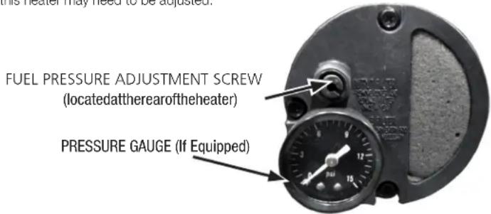
ADJUSTMENT PROCEDURE
- Fill fuel tank.
- Start heater.
- Locate the pressure adjustment screw, located on the back of the power pack assembly and accessible by the handle of the heater.
- Remove the rubber cap over the fuel pressure adjustment screw.
- Using a flat bladed screw driver, turn the pump pressure adjustment screw:
- clockwise to increase pump pressure
• counter-clockwise to decrease pump pressure
By using the installed pressure gauge (if equipped) you may quantitatively calibrate the pressure. The manufacturer's recommended pump pressures are in the specifications chart on page 3. - The desired qualitative burner characteristics are that the nose cone in the combustion chamber should be cherry red with no dark spots and the flame should not extend beyond the nose cone.
IMPROPER PRESSURE ADJUSTMENT
Problem: Heater does not have a strong consistent flame.
Heater smokes and spits raw fuel.
Nose cone does not get cherry red.
Adjustment: Pump pressure is too low.
Turn adjustment screw clockwise to increase pump pressure
Problem: Flame extends beyond the end of the heater.
Adjustment: Pump pressure is too high.
Turn adjustment screw counter clockwise to decrease pump pressure.
Daily Maintenance Schedule
-
GENERAL. Make general visual inspection of heater for loose or damaged parts. Check nuts and bolts to insure against looseness caused by vibration or rough handling. Damaged parts should be repaired or replaced before using heater again. Check heater operation to be sure it is operating normally (See "Servicing" section for description of normal operation).
-
FILTERS. Dirty air or fuel filters will cause an imbalance in the air-fuel mixture. The best indication that this condition exists is an increase in odours or difficulty getting your heater to ignite. This heater should never be operated without the filters in place. If required, clean filters as described under "500 Hours" and "Annual Schedules".
500 Hour Maintenance Schedule
- AIR INTAKE FILTER. Remove and wash the filter element with a mild detergent, dry thoroughly and replace. Do not oil the filter element. If your heater is used where there is considerable dust or dirt, clean as often as necessary (approximately every 50 hrs.).
- REMOVE DUST. Clean heater twice a season (more often under dusty conditions). Remove accumulated dust from the transformer, burner, motor and fan blades with compressed air. Wipe area clean with a clean dry cloth. Inspect area to insure all foreign materials are removed, especially around the burner and combustion area. Safety glasses should be worn when using compressed air.
- CAD CELL. Clean the glass portion of the cad cell with a soft dry cloth.
- NOZZLE. Accumulation of dirt from fuel and carbon from the compressor vanes will eventually fill up the passages in the nozzle, resulting in reduction of fuel and air flow. Pressure will gradually increase giving improper fuel-air mixture and excess odour and smoke. If this occurs, replace the fuel nozzle.
- FUEL TANK. Clean twice a season (during frequently used periods, clean twice a month). Drain and flush the fuel tank with clean fuel oil. Make sure to dispose of waste fuel properly.
Annual Maintenance Schedule
- AIR OUTPUT FILTER. Remove the air output filter and tap the contaminated side gently on a solid object to remove contaminates. Compressed air or liquids should not be used to clean this filter. Reinstall cleaned filter in filter body in the same position as it was when removed. If the filter appears extremely dirty, replace it with a new filter of the same type. When replacing the filter cover, be sure the gasket is firmly in place and the screws in the filter cover are tight to prevent air leaks.
- FUEL FILTER. Remove the fuel filter from fuel line and direct compressed air through the filter in the opposite direction of fuel flow. Safety glasses should be worn when using compressed air.
- AIR AND FUEL LINES. If the air or fuel lines are removed during cleaning, be sure all connections are tight before operating unit.
Store the heater in a dry location free from fumes or dust.
At the end of each heating season, clean the heater as described in the MAINTENANCE section. Drain and flush the fuel tank with clean fuel. The manufacturer recommends completely filling the tank with fuel for extended storage to minimize condensation inside the tank.
It is recommended to only store diesel in containers that are marked "DIESEL".
Servicing
⚠ WARNING: A hazardous condition may result if a heater is used that has been modified or is not functioning properly.
When the heater is working normally:
* The flame is contained within the heater.
* The flame is essentially yellow.
* There is no strong disagreeable odour, eye burning or other physical discomfort.
* There is not smoke or soot internal or external to the heater.
* There are no unplanned or unexplained shutdowns of the heater.
Troubleshooting
High limit switch open circuit
- Make sure heater is cooled off, toggle switch to "OFF" position, wait 5 minutes and retry.
Sparks, calling for flame, but no or slow motor operation
-
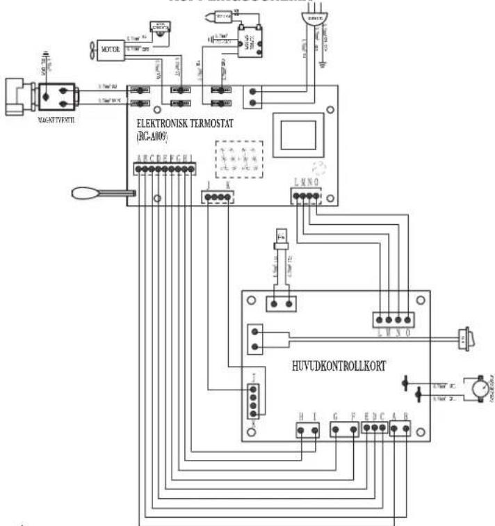
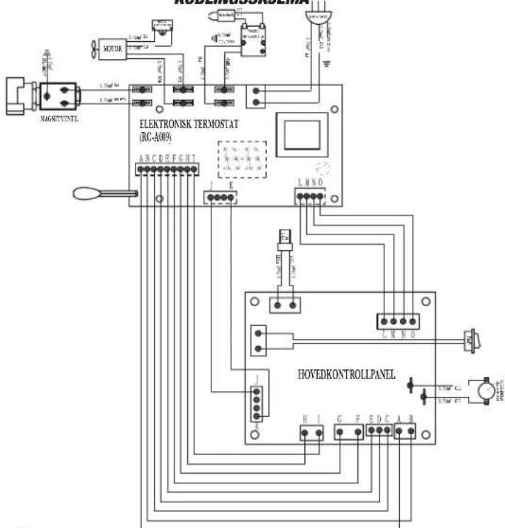
Check wiring to motor (per wiring schematic in manual)
-
Make sure that the pressure gauge is in place and not damaged
-
Adjust pressure for proper heater operation per manual
-
With heater disconnected from AC source, rotate fan clockwise to verify motor is free
-
Remove air filter housing from motor and inspect the pump rotor for damage. If damaged, replace rotor assembly.
-
If wiring is correct, pump rotor is okay, and motor is not rotating freely, replace motor or power-pack assembly.
-
If problem persists, replace oil flame control assembly.
-
Check for spark arcing from the electrode assembly, to the combustion cylinder.
-
Check the cad cell for continuity.
No Spark
- Check length and gauge of extension cord for proper amp. draw (check page 5)
- Check wiring to igniter (per wiring schematic in manual)
- Check gap between electrode probes (2.3 - 3mm)
- Still no spark, replace igniter assembly
- Replace oil flame control assembly
Abnormal Motor Operation - Motor overheats or Stops
- Motor speed too low (Motor should operate at 3450 rpm) - Replace motor
- With heater disconnected from AC source, rotate fan clockwise to verify motor is free
- Remove air filter housing from motor and inspect the pump rotor for damage. If damaged, replace rotor assembly
- If wiring is correct, pump rotor is okay, and motor is not rotating freely, replace motor or power-pack assembly
- Replace oil flame control assembly
Unable to Detect Flame
- Check wiring to cad cell (per wiring schematic in manual)
- Clean cad cell photo cell
a) Slide cad cell out of cad cell holder
b) Push the photo cell out of the black rubber cad cell housing by pushing on the 2 purple wires
c) Clean the photo cell with a soft cloth and rubbing alcohol
d) Pull the photo cell back into the cad cell housing and reinstall into holder
e) Test heater
-
If the heater still does not operate, replace cad cell
-
Replace oil flame control assembly
Flame Control Failure
- Check wiring in heater (per wiring schematic in manual).
- Replace oil flame control assembly.
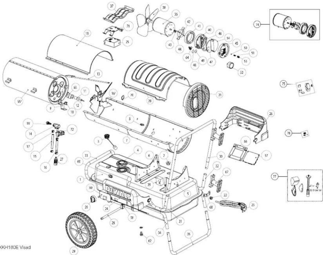
DXKH080E
DXKH125E
DXKH180E
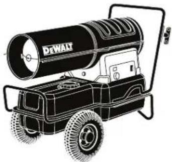
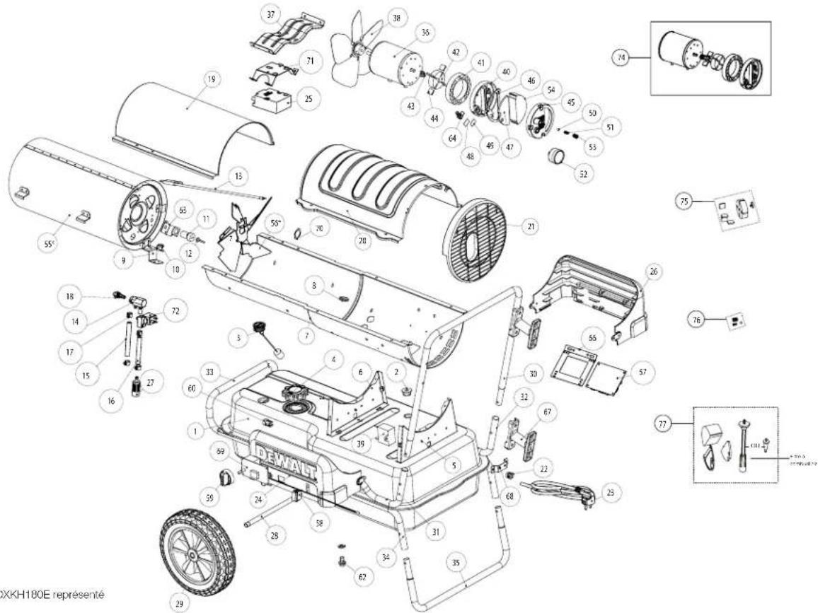
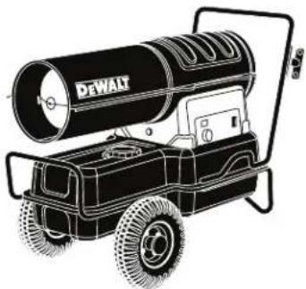
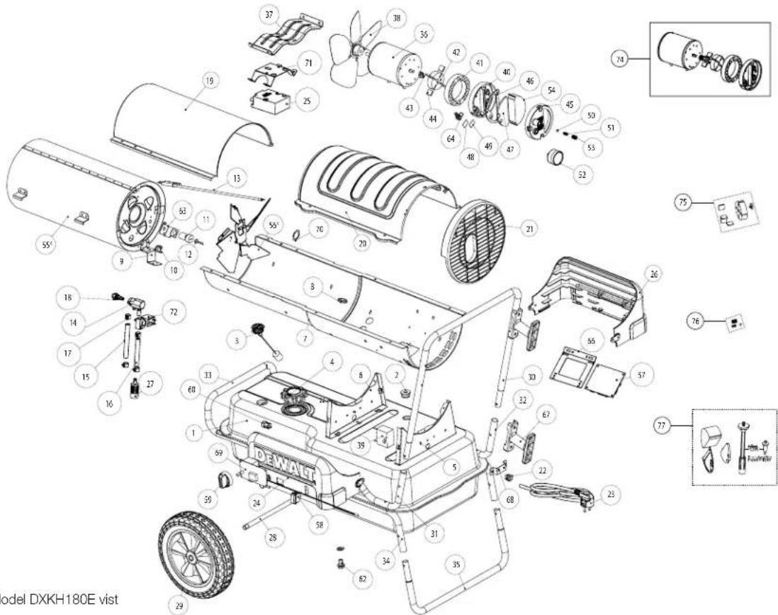
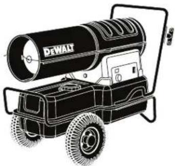
* Model DXKH180E Shown
REPLACEMENT PARTS LIST
NEVER LEAVE THE HEATER UNATTENDED WHILE BURNING!
| #DXKH080EDXKH125EDXKH180EDescription | ||||
| 1 | 27175 27225 | 27226 Fuel Tank | ||
| 2 | 27176 27176 | 27176 Fuel Filter Rubber Grommet | ||
| 3 | 27177 27177 | 27177 Fuel Gauge | ||
| 4 | 26959 26959 | 26959 Fuel Tank Cap | ||
| 5 | n/a n/a n/a | Rear Saddle Bracket | ||
| 6 | n/a n/a n/a | Front Saddle Mount | ||
| 7 | 27210 27211 | 27212 | Lower Barrel | |
| 8 | 27179 27179 | 27179 Grommel | ||
| 9 | 27180 27180 | 27180 | High Limit Switch Bracket | |
| 10 | 27181 27 | 181 27181 | High Limit Switch | |
| 11 | F226865 | F226865 | F226865 | Photo Cell Assembly |
| 12 | n/a n/a n/a | Photo Cell Sensor (see # 11) | ||
| 13 | 27182 27 | 182 27182 Igniter Electrode | ||
| 14 | 27183 27 | 183 27183 | Nozzle Adapter | |
| 15 | 27185 27 | 231 27231 Rubber Air Tube | ||
| 16 | 27184 27 | 233 27233 | Rubber Fuel Tube | |
| 17 | n/a | n/a | n/a | Fuel Line Clamp (source at your local hardware store) |
| 18 | 27186 27 | 235 27207 | Nozzle | |
| 19 | 27213 27 | 214 27215 | Front Cover | |
| 20 | 27288 27 | 217 27218 Rear Cover | ||
| 21 | 27189 27 | 237 27237 | Inlet Grill | |
| 22 | n/a n/a n/a | Strain Relief | ||
| 23 | n/a n/a n/a | Power Cord | ||
| 24 | 27289 27 | 283 27286 | Control Side Left Saddle | |
| 25 | 27208 27 | 208 27208 | Transformer | |
| 26 | 27290 27 | 284 27287 | Right Saddle | |
| 27 | n/a n/a n/a | Oil Filter (see # 75) | ||
| 28 | n/a | 27239 27240 | Wheel Axle | |
| 29 | n/a | 27241 27242 | Wheel | |
| 30 | 27291 27 | 274 27274 | Transport Handle | |
| 31 | n/a | 27243 27243 | Left Lift Handle | |
| 32 | n/a | 27245 27245 | Right Lift Handle | |
| 33 | n/a | 27247 27248 | Front Lift Handle | |
| 34 | n/a | 27249 | 27249 | Lower Foot Adapter Tube |
| 35 | n/a | 27251 27251 | Foot | |
| 36 | n/a n/a n/a | Motor (see # 72) | ||
| 37 | 27193 27 | 253 27253 Motor Bracket | ||
| #DXKH080EDX KH125EDXKH-180EDescription | ||||
| 38 | 27194 27 | 255 27256 | Fan Blade | |
| 39 | 27209 27 | 294 27294 | Capacitor | |
| 40 | n/a n/a | /va | Pump Plate (see # 72) | |
| 41 | n/a n/a | /va | Pump Ring (see # 72) | |
| 42 | n/a n/a | /va | Rotor (see # m and 73) | |
| 43 | n/a n/a | /va | Plastic Pump Drive Key (see # 72 or 73) | |
| 44 | n/a n/a | /va | Vanes (see # 72 or 73) | |
| 45 | n/a n/a | /va | Plastic Inlet Housing (see # 72) | |
| 46 | n/a n/a | /va | Inlet Housing Gasket (see # 75) | |
| 47 | n/a n/a | /va | Filter (see # 75) | |
| 49 | n/a | 27197 | n/a | Small Foam Filter (see # 75) |
| 50 | n/a n/a | /va | Steel Ball Bearing (see # 74) | |
| 51 | n/a n/a | /va | Adjustment Spring (see # 74) | |
| 52 | n/a | 27273 27 | 273 | Pressure Gauge |
| 53 | n/a n/a | /va | Pump Adjustment Screw (see # 74) | |
| 54 | n/a n/a | /va | Large Dustproof Sponge (see # 75) | |
| 55 | 27198 27 | 257 27258 | Combustion Chamber Assembly* | |
| 56 | n/a n/a | /va | Air Deflector Assembly (see # 55)* | |
| 57 | 27295 27 | 295 27295 | Circuit Board | |
| 58 | 27200 27 | 200 27200 | Single Pole Switch | |
| 59 | 27292 27 | 282 27282 | Thermostat Knob | |
| 60 | n/a | 27260 27 | 260 | Handle Tube Plug |
| 62 | n/a | 27262 | 27262 | Drain Plug with Gasket |
| 63 | 27202 27 | 202 27202 | Photo Cell Bracket | |
| 64 | n/a n/a | /va | Brass Barb Elbow | |
| 66 | 27203 27 | 203 27203 | Circuit Board Bracket | |
| 67 | n/a | 27263 27 | 264 | Cord Wrap |
| 68 | n/a | 27265 27 | 266 | Metal Standoff |
| 69 | 27296 27 | 296 27296 | Thermostat Board | |
| 70 | n/a n/a | /va | Spring Clip (180K Only) | |
| 71 | 27297 27 | 297 27297 | Ignition Transformer Bracket | |
| 72 | 27298 27 | 298 27298 | Electromagnetic Valve | |
| 73 | n/a | 27269 | 27269 | Wheel Hardware Kit (not pictured) |
| 74 | 27205 27 | 271 27272 | Power Pack | |
| 75 | F226831 | F226831 | F226831 | Rotor Kit |
| 76 | F206842 | F206842 | F206842 | Adjustment Kit |
| 77 | F221887 | F221887 | F221887 | Filter Kit |
* DXKH180E Shown
CAUTION: The parts lists and wiring diagram show the heater as it was constructed. Do not use a heater which is different from that shown. Heater performance is affected by air pressure setting. If there is any uncertainty about the air pressure setting, have it checked. A heater which is not working right must be repaired, but only by a trained, experienced service person.
We
EC Declaration of Conformity
| Company Name:Postal Address:Postcode and city:E-Mail address: | Enerco Group, Inc.4560 West 160th StreetCleveland, OH 44132jeff.bunsey@us-egi.com |
Declare that the DoC issued under our sole responsibility and belong to the following products:
| Apparatus model/products FORCED-AIR | HEATER |
| Type: DXKH080E/DXKH125E/DXKH180E | |
| Function: Heating |
The object of the declaration described above is in conformity with the EC directives:
| Machinery Directive 2006/42/EC | |
| RoHs Directive 2011/65/EU |
The following harmonized standards and technical specification have been applied
| EN.13842-2004 | Oil fired forced convection air heaters - Stationary and transportable for space heating |
| EN.60335-1:2016 | Safety of household and similar electrical appliances-part 1: general requirements |
| EN 267:2009+A1 | Automatic forced draught burners for liquid fuels |
| EN 298:2012 | Automatic burner control systems for burners and appliances burning gaseous or liquid fuels |
Importer:
SAM-Works UK Ltd
Hemel Hempstead,
United Kingdom
Signature:

Senior Manager, Global Process &
Efficiency Engineering
Enerco Group Inc.
Cleveland, 14.09.2020
Diesel Forced Air Heater
DXKH080E
DXKH125E
DXKH180E
natural_image
Line drawing of a portable electric heater with a large cylindrical tube (no text or symbols)▲ Warning
USE ONLY MANUFACTURER'S REPLACEMENT PARTS. USE OF ANY OTHER PARTS COULD CAUSE INJURY OR DEATH. REPLACEMENT PARTS ARE ONLY AVAILABLE DIRECT FROM THE FACTORY AND MUST BE INSTALLED BY A QUALIFIED SERVICE AGENCY.
PARTS ORDERING INFORMATION:
PURCHASING: Accessories may be purchased at any DEWALT® local dealer or direct from the factory.
FOR INFORMATION REGARDING SERVICE:
www.DEWALT.com
www.2helpU.com
Please include the model number, date of purchase, and description of problem in all communication.
LIMITED WARRANTY
DeWALT® warrants its heaters and accessories to be free from defects in material and workmanship for a period of 2 years from date of purchase. DeWALT® will repair or replace this product free of charge if it has been proven to be defective within the 2 year period, and is returned at customer expense with proof of purchase to DeWALT® within the warranty period.
For Sale in the following countries:

GB

DE

FR

11

NI

DK

SE

FI

NO
DrWALT®, GUARANTEED TOUGH® and the yellow and black color scheme are trademarks of the DeWALT Industrial Tool Co., used under license. ©2020 DeWALT. EGI/Enerco Group Inc. Unde license from DeWALT Industrial Tool Co

⚠️ WARNING: ALLGEMEINE GEFAHR
natural_image
Close-up of a mechanical pressure gauge with a dial and pointer, no visible text or symbolsDXKH080E
DXKH125E
DXKH180E
DXKH180E Abgebildet
Senior Manager, Global Process &
Efficiency Engineering
Enerco Group Inc.
Cleveland, 14.09.2020
natural_image
Line drawing of a portable electric water heater with a large cylindrical tube (no text or symbols)
Warnung
natural_image
Close-up of a mechanical pressure gauge with a dial and adjustment knob (no visible text or symbols)NE JAMAIS LAISSER L'APPAREIL DE CHAUFFAGE SANS SURVEILLANCE QUAND IL FONCTIONNE
PROCEDURE DE RÉGLAGE
DXKH080E
NE JAMAIS LAISSER L'APPAREIL DE CHAUFFAGE SANS SURVEILLANCE QUAND IL FONCTIONNE
DXKH125E
DXKH180E
| Directive Machines 2006/42/EC | |
| Directive RoHs 2011/65/EU |
Jeff Bunsey
Senior Manager, Global Process &
Efficiency Engineering
Enerco Group Inc.
Cleveland, 14.09.2020
NE JAMAIS LAISSER L'APPAREIL DE CHAUFFAGE SANS SURVEILLANCE QUAND IL FONCTIONNE
DEWALT®
MANUEL D'UTILISATION
natural_image
Line drawing of a portable electric heater with a large cylindrical tube (no text or symbols)Avertissement
UTILISEZ UNIQUEMENT DES PIÈCES DE RECHANGE DU FABRICANT. L'UTILISATION D'AUTRES PIÈCES POURRAIT PROVOQUER DES BLESSURES OU LA MORT. LES PIÈCES DE RECHANGE SONT DISPONIBLES UNIQUEMENT À L'USINE ET DOIVENT ÊTRE INSTALLÉES PAR UNE AGENCE DE SERVICE QUALIFIÉE.
natural_image
Close-up of a mechanical pressure gauge with adjustment knobs and a circular housing (no visible text or symbols)NON LASCIARE MAI IL RISCALDATORE INCUSTODITO DURANTE LA COMBUSTIONE!
DXKH080E
NON LASCIARE MAI IL RISCALDATORE INCUSTODITO DURANTE LA COMBUSTIONE!

DXKH125E
* DXKH180E mostrato
DXKH180E
NON LASCIARE MAI IL RISCALDATORE INCUSTODITO DURANTE LA COMBUSTIONE!
Senior Manager, Global Process &
Efficiency Engineering
Enerco Group Inc.
Cleveland, 14.09.2020
NON LASCIARE MAI IL RISCALDATORE INCUSTODITO DURANTE LA COMBUSTIONE!
DEWALT®
MANUALE D'USO
natural_image
Line drawing of a portable water heater with a large cylindrical tube (no text or symbols)Avvertenza
UTILIZZARE SOLO COMPONENTI DI RICAMBIO DEL COSTRUTTORE. L'UTILIZZO DI ALTRE COMPONENTI POTREBBE CAUSARE LESIONI O MORTE. I COMPONENTI DI RICAMBIO SONO DISPONIBILI SOLO DIRETTAMENTE DALLA FABBRICA E DEVONO ESSERE INSTALLATI DA UN CENTRO DI ASSISTENZA QUALIFICATO.
⚠ WAARSCHUWING: VERBRANDINGS-, INADEMINGS- EN EXPLOSIE-
GEVAAR. HOUD BRANDBAAR MATERIAAL, ZOALS BOUWMATERIAAL, PAPIER OF KARTON, OP VEILIGE AFSTAND VAN DE KACHEL, ZOALS AANBEVOLEN DOOR DE INSTRUCTIES. GEBRUIK DE KACHEL NOOIT IN RUIMTES DIE VLUCHTIGE OF IN DE LUCHT AANWEZIGE BRANDSTOF-FEN BEVATTEN, OF PRODUCTEN ZOALS BENZINE, OPLOSMIDDELEN, VERDUNNER, STOFDEELTJES OF ONBEKENDE CHEMICALIËN.
⚠ WAARSCHUWING: ALGEMEEN GEVAAR
HET NIET NALEVEN VAN DE VOORZORGSMAATREGELEN EN INSTRUCTIES MEEGELEVERD MET DEZE KACHEL KAN LEIDEN TOT DE DOOD, ERNSTIG LETSEL EN SCHADE AAN EIGENDOMMEN OF SCHADE DOOR GEVAAR VOOR BRAND, EXPLOSIE, VERBRANDING, VERSTIKKING, KOOLMONOXIDEVERGIFTIGING EN/OF ELEKTRICITEIT.
ALLEEN PERSONEN DIE DE INSTRUCTIES BEGRIJPEN EN OPVOLGEN, MOGEN DEZE KACHEL GEBRUIKEN OF ONDERHOUDEN.
INDIEN U ONDERSTEUNING OF INFORMATIE OVER DE KACHEL NODIG HEEFT ZOALS EEN HANDLEIDING, LABELS, ENZ. NEEM DAN CONTACT OP MET DE FABRIKANT. BEWAAR DEZE INSTRUCTIES VOOR TOEKOMSTIG GEBRUIK.
⚠ WAARSCHUWING: KOOLMONOXIDE KAN DODELIJK ZIJN
HET GEBRUIK VAN EEN DRAAGBARE KACHEL IN EEN AFGESLOTEN RUIMTE KAN DODELIJKE KOOLMONOXIDE PRODUCEREN.
⚠ WAARSCHUWING: NIET VOOR THUISGEBRUIK OF GEBRUIK IN CARAVANS OF CAMPERS.
⚠ WAARSCHUWING: Voor Model DXKH080E
WIEL AND HANDVAT MONTAGE
Abnormale Motor Werking - Motor oververhit of Stopt
DXKH080E
LAAT EEN BRANDENDE KACHEL NOOIT ONBEHEERD ACHTER!

DXKH125E
Senior Manager, Global Process &
Efficiency Engineering
Enerco Group Inc.
Cleveland, 14.09.2020
LAAT EEN BRANDENDE KACHEL NOOIT ONBEHEERD ACHTER!
DEWALT®
GEBRUIKERSHANDLEIDING
Diesel Heteluchtkanon
DXKH080E
DXKH125E
DXKH180E
natural_image
Illustration of a DeWalt water heater with a cylindrical tube mounted on a wheeled cart (no text or symbols)▲ Waarschuwing
GEBRUIK ALLEEN VERVANGINGSONDERDELEN VAN DE FABRIKANT. GEBRUIK VAN ANDERE ONDERDELEN KAN LETSEL OF DE DOOD VEROORZAKEN. VERVANGINGSONDERDELEN ZIJN ALLEEN DIRECT VERKRIJGBAAR IN DE FABRIEK EN MOETEN WORDEN GEINSTALLEERD DOOR EEN GEKWALIFICEERD ONDERHOUDSMONTEUR.
BESTELINFORMATIE VOOR DE ONDERDELEN:
DXKH080E, DXKH125E, DXKH180E
DXKH080E
ÄLÄ KOSKAAN JÄTÄ LÄMMITINTÄ ILMAN VALVONTAA SEN PALAESSA
DXKH125E
* Kuvassa DXKH180E
DXKH180E
VARAOSALUETTELO
ÄLÄ KOSKAAN JÄTÄ LÄMMITINTÄ ILMAN VALVONTAA SEN PALAESSA!
| #DXKH080EDXK | KH125EDXKH | 180EKuvaus | |
| 1 27175 27225 | 27226 Politoainesäiliö | ||
| 2 27176 27176 | 27176 Politoinesuodattimen läpivientikumi | ||
| 3 27177 27177 | 27177 Politoinemittari | ||
| 4 26959 26959 | 26959 Politoinesäillön korkki | ||
| 5 ei sovellu ei sovellu ei sovellu | Takasatulakahva | ||
| 6 ei sovellu ei sovellu ei sovellu | Etusatulakahva | ||
| 7 27210 27211 | 27212 | Alempi kuori | |
| 8 27179 27179 | 27179 | Läpivienttilviste | |
| 9 27180 27180 | 27180 | Ylärajakytkimen kiinnike | |
| 10 27181 27181 | 27181 | Ylärajakytkin | |
| 11 F226865 | F226865 | F226865 | Valokennon rakennaosa |
| 12 ei sovellu ei sovellu ei sovellu | Valokennon anturi (ks. i11) | ||
| 13 27182 27182 | 27182 Sytytinoloktrodi | ||
| 14 27183 27183 | 27183 | Suuttimen sovttin | |
| 15 27185 27231 | 27231 | Kuminen ilmaputki | |
| 16 27184 27233 | 27233 | Kuminen politoaineputki | |
| 17 ei sovellu ei sovellu ei sovellu | Politoasineputken puristin (hanki paikallisesta rautakaupasta) | ||
| 18 27186 27235 | 27207 | Suutin | |
| 19 27213 27214 | 27215 | Etukansi | |
| 20 27288 27217 | 27218 | Takakansi | |
| 21 27189 27237 | 27237 | Tuloritilä | |
| 22 ei sovellu ei sovellu ei sovellu | Vedonpoistin | ||
| 23 ei sovellu ei sovellu ei sovellu | Virtajohto | ||
| 24 27289 27283 | 27286 | Ohjainpuolen vasen satula | |
| 25 27208 27208 | 27208 | Muuuntaja | |
| 26 27290 27284 | 27287 | Olkea satula | |
| 27 ei sovellu ei sovellu ei sovellu | Öljynsuodatin (ks. #75) | ||
| 28 ei sovellu | 27239 27240 | Pyörän akselli | |
| 29 ei sovellu | 27241 27242 | Pyörä | |
| 30 27291 27274 | 27274 | Kuljetuskahva | |
| 31 ei sovellu | 27243 | 27243 | Vason nostokahva |
| 32 ei sovellu | 27245 | 27245 | Olkea nostokahva |
| 33 ei sovellu | 27247 27248 Etunostakahva | ||
| 34 ei sovellu | 27249 | 27249 | Alempi jalan sovtinputki |
| 35 ei sovellu | 27251 27251 | Jalka | |
| 36 ei sovellu ei sovellu ei sovellu | Moottori (ks. #72) | ||
| 37 27193 27253 | 27253 | Moottorin kiinnike | |
Senior Manager, Global Process &
Efficiency Engineering
Enerco Group Inc.
Cleveland, 14.09.2020
ÄLÄ KOSKAAN JÄTÄ LÄMMITINTÄ ILMAN VALVONTAA SEN PALAESSA
DEWALT®
KÄYTTÖOHJE
natural_image
Illustration of a portable water heater with a large cylindrical tube labeled 'DEWALT' on its side, mounted on a wheeled cart (no additional text or symbols)Varoitus
KÄYTÄ VAIN VALMISTAJAN VARAOSIA. MUIDEN OSIEN KÄYTTÖ VOI AIHEUTTAA VAMMOJA TAI KUOLEMAN. VARAOSIA ON SAATAVANA VAIN SUORAAN TEHTAALTA JA NIIDEN ASENNUS ON ANNETTAVA PÄTEVÄN HUOLTOEDUSTAJAN TEHTÄVÄKSI.
OSIEN TILAUSTIEDOT:
DXKH080E, DXKH125E, DXKH180E Diesel Luftvärmare
CE 0197/20 EN-13842:2004
SPARA DESSA INSTRUKTIONER
⚠️ WARNING: ALLMÄN FARA
MISSLYCKAN MED ATT UPPFYLLA DE FÖRSIKTIGHETSÄTGÄRDER OCH ANVISNINGAR SOM TILLHANDAHÄLLS MED DENNA VÄRMARE, KAN LEDA TILL DÖDSFALL, ALLVARLIGA KROPPSSKADOR OCH FÖRLUST AV EGENDOM ELLER SKADA GENOM BRAND, EXPLOSION, KVÄVNING, KOLMONOXIDFÖRGIFTNING, OCH/ ELLER ELEKTRISK CHOCK.
ENDAST PERSONER SOM KAN FÖRSTÅ OCH KAN FÖLJA DENNA INSTRUKTION BÖR ANVÄNDA ELLER SERVA DENNA VÄRMEFLÄKT.
OM DU BEHÖVER ASSISTANS ELLER INFORMATION OM VÄRMAREN, SÄSOM EN INSTRUKTIONS MANUAL, ETIKETTER, ETC. KONTAKTA TILLVERKAREN OCH SPARA DESSA INSTRUKTIONER FÖR FRAMTIDA REFERENS.
⚠️WARNING: KOLMONOXID KAN DÖDA DIG
ANVÄNDNING AV EN BÄRBAR VÄRMARE I ETT SLUTET OMRÅDE KAN PRODUCERA DÖDLIG KOLMONOXID.
⚠️VARNING: EJ FÖR ANVÄNDNING I HEM ELLER REKREATIONS FORDON.
DXKH080E
LÄMNA ALDRIG VÄRME ELEMENTET UTAN TILLSYN VID ANVÄNDNING!
DXKH125E
* DXKH180E Visad
DXKH180E
RESERVDELAR LISTA
LÄMNA ALDRIG VÄRME ELEMENTET UTAN TILLSYN VID ANVÄNDNING!
| #DXKH080EDXKH125EDXKH180EBeskrivning | ||||
| 1 | 27175 27225 | 27226 Bränselank | ||
| 2 | 27176 27176 | 27176 Bräns filter Gumm skydd | ||
| 3 | 27177 27177 | 27177 Bränslemåtare | ||
| 4 | 26959 26959 | 26959 Bränsetanklock | ||
| 5 | Ej tillämplig Ej | jillämplig | Ej tillämplig | Bakre sadelfäste |
| 6 | Ej tillämplig Ej | jillämplig | Ej tillämplig | Framsadelmontering |
| 7 | 27210 27211 | 27212 Nedre trumma | ||
| 8 | 27179 27179 | 27179 Skyddshylsa | ||
| 9 | 27180 27180 | 27180 Hög begränsningskontaktfäste | ||
| 10 | 27181 27181 | 27181 | Hög gränslägesbrytare | |
| 11 | F226865 | F226865 | F226865 | Fotocellmontering |
| 12 | Ej tillämplig Ej | jillämplig | Ej tillämplig | Fotocellsensor (se # 11) |
| 13 | 27182 27182 | 27182 | Tändelektrod | |
| 14 | 27183 27183 | 27183 | Munstyckesadapter | |
| 15 | 27185 27231 | 27231 | Gummilufrör | |
| 16 | 27184 27233 | 27233 Gummiföringsrör | ||
| 17 | Ej tillämplig Ej | jillämplig | Ej tillämplig | Bränsleodning (hitta i din lokala jämaffär) |
| 18 | 27186 27235 | 27207 | Munstycke | |
| 19 | 27213 27214 | 27215 | Framsida | |
| 20 | 27288 27217 | 27218 | Bakre lock | |
| 21 | 27189 27237 | 27237 | Inloppsgrill | |
| 22 | Ej tillämplig Ej | jillämplig | Ej tillämplig | Dragavlastning |
| 23 | Ej tillämplig Ej | jillämplig | Ej tillämplig | Strömsladd |
| 24 | 27289 27283 | 27286 Kontrollsida vänster sadel | ||
| 25 | 27208 27208 | 27208 | Transformator | |
| 26 | 27290 27284 | 27287 | Höger sadel | |
| 27 | Ej tillämplig Ej | jillämplig | Ej tillämplig | Oljefilter (se # 75) |
| 28 | Ej tillämplig | 27239 27240 | Hjulaxel | |
| 29 | Ej tillämplig | 27241 27242 | Hjul | |
| 30 | 27291 27274 | 27274 | Transporthandtag | |
| 31 | Ej tillämplig | 27243 | 27243 | Vänsterlyfthandtag |
| 32 | Ej tillämplig | 27245 | 27245 | Höger lyfthandtag |
| 33 | Ej tillämplig | 27247 | 27248 | Framlyfthandtag |
| 34 | Ej tillämplig | 27249 | 27249 | Nedre fotadapternör |
| 35 | Ej tillämplig | 27251 27251 | Fol | |
| 36 | Ej tillämplig Ej | jillämplig | Ej tillämplig | Motor (se # 72) |
| 37 | 27193 27253 | 27263 | Motorläste | |
| #DXKH080EDX | KH125EDXKH | 180EBeskrivning | ||
| 38 | 27194 27255 | 27256 | Fläktblad | |
| 39 | 27209 27294 | 27294 | Kondensator | |
| 40 | Ej tillämplig | Ej tillämplig | Ej tillämplig | Pumpplatta (se # 72) |
| 41 | Ej tillämplig | Ej tillämplig | Ej tillämplig | Pumpring (se # 72) |
| 42 | Ej tillämplig | Ej tillämplig | Ej tillämplig | Rotor (se # m och 73) |
| 43 | Ej tillämplig | Ej tillämplig | Ej tillämplig | Plastdrivmyckel (se # 72 eller 73) |
| 44 | Ej tillämplig | Ej tillämplig | Ej tillämplig | Skovlar (se nr 72 eller 73) |
| 45 | Ej tillämplig | Ej tillämplig | Ej tillämplig | Plastinloppshus (se # 72) |
| 46 | Ej tillämplig | Ej tillämplig | Ej tillämplig | Packning i inloppshus (se # 75) |
| 47 | Ej tillämplig | Ej tillämplig | Ej tillämplig | Filter (se # 75) |
| 49 | Ej tillämplig | 27197 | Ej tillämplig | Litet skumfilter (se # 75) |
| 50 | Ej tillämplig | Ej tillämplig | Ej tillämplig | Stälkullager (se # 74) |
| 51 | Ej tillämplig | Ej tillämplig | Ej tillämplig | Justeringsfäder (se # 74) |
| 52 | Ej tillämplig | 27273 27273 | Trycknätare | |
| 53 | Ej tillämplig | Ej tillämplig | Ej tillämplig | Pumpjusteringsskruv (se # 74) |
| 54 | Ej tillämplig | Ej tillämplig | Ej tillämplig | Stor dammtät svamp (se # 75) |
| 55 | 27198 27257 | 27258 | Förbränningskammarförsamlingen * | |
| 56 | Ej tillämplig | Ej tillämplig | Ej tillämplig | Luftavdeflektor (se # 55) * |
| 57 | 27295 27295 | 27295 | Kretskort | |
| 58 | 27200 27200 | 27200 Enpolig switch | ||
| 59 | 27292 27282 | 27282 | Termostatvred | |
| 60 | Ej tillämplig | 27260 27260 | Handtag rörplugg | |
| 62 | Ej tillämplig | 27262 27262 | Avtaopningsplugg med packning | |
| 63 | 27202 27202 | 27202 Fotocellfäste | ||
| 64 | Ej tillämplig | Ej tillämplig | Ej tillämplig | Mässingstängbåge |
| 66 | 27203 27203 | 27203 | Kretskortsfäste | |
| 67 | Ej tillämplig | 27263 27264 | Sladdisomslag | |
| 68 | Ej tillämplig | 27265 27266 | Metallavständ | |
| 69 | 27296 27296 | 27296 | Termostatkort | |
| 70 | Ej tillämplig | Ej tillämplig | Ej tillämplig | Fjäderklämma (endast 210K) |
| 71 | 27297 27297 | 27297 | Tändtransformatorläste | |
| 72 | 27298 27298 | 27298 | Electromagnetic Valve | |
| 73 | Ej tillämplig | 27269 27269 | Hjulhärdvarukit (ej bild) | |
| 74 | 27205 27271 | 27272 | Strömsats | |
| 75 | F226831 F | F226831 | F226831 | Rotorsats |
| 76 | F206842 | F206842 | F206842 | Justeringssats |
| 77 | F221887 F | F221887 | F221887 | Filtorkit |
* DXKH180E Visad
LÄMNA ALDRIG VÄRME ELEMENTET UTAN TILLSYN VID ANVÄNDNING!
KOPPLINGSSCHEMA
Senior Manager, Global Process &
Efficiency Engineering
Enerco Group Inc.
Cleveland, 14.09.2020
LÄMNA ALDRIG VÄRME ELEMENTET UTAN TILLSYN VID ANVÄNDNING!
DEWALT®
INSTRUKTIONSHANDBOK
Diesel Luftvärmare
DXKH080E
DXKH125E
DXKH180E
natural_image
Illustration of a black and white industrial device resembling a cylindrical device with 'DEWALT' branding (no additional text or symbols)▲ Varning
ANVÄND ENDAST ERSÄTTNINGSDELAR FRÅN TILLVERKAREN. ANVÄNDNING AV ANDRA DELAR KAN ORSAKA SKADA ELLER DÖD. ERSÄTTNINGSDELAR ÅR BARA TILLGÅNGLIGA DIREKT FRÅN FABRIKEN OCH MÅSTE INSTALLERAS AV EN KVALIFICERAD SERVICE FÖRMEDLING
BESTÄLLNING AV DELAR INFORMATION:
FÖR INFORMATION OM SERVICE:
www.DEWALT.com
www.2helpU.com
EKSTRA LEDNINGSHOLDER
DXKH080E
FORLAT ALDRI VARMEAPPARATET UTEN TILSYN MENS DET BRENNER!

DXKH125E
DXKH180E vist
DXKH180E
LISTE OVER RESERVEDELER
FORLAT ALDRI VARMEAPPARATET UTEN TILSYN MENS DET BRENNER!
| #DXKH080EDXKH125EDXKH180EBeskrivelse | ||||
| 1 | 27175 27225 | 27226 Bensintank | ||
| 2 | 27176 27176 | 27176 Gummistropp for drivstofffilter | ||
| 3 | 27177 27177 | 27177 Drivstoffmåler | ||
| 4 | 26959 26959 | 26959 Lokk for bensintank | ||
| 5 | Ingen ingen ingen | Feste for bakre aksellager | ||
| 6 | Ingen ingen ingen | Feste for fremre aksellager | ||
| 7 | 27210 27211 | 27212 | Nedre tonne | |
| 8 | 27179 27179 | 27179 Gummistropp | ||
| 9 | 27180 27180 | 27180 | Feste for høy grensebryter | |
| 10 | 27181 27181 | 27181 | Høy grensebryter | |
| 11 | F226865 | F226865 | F226865 | Fotocolleanordning |
| 12 | ingen ingen ingen | Fotocellesensor (se # 11) | ||
| 13 | 27182 27182 | 27182 | Tenner elektrode | |
| 14 | 27183 27183 | 27183 | Dyseadapter | |
| 15 | 27185 27231 | 27231 | Gummiluftror | |
| 16 | 27184 27233 | 27233 | Gummibensinror | |
| 17 | ingen ingen ingen | Klemme for drivstoffledning (finn på din lckale jamwarehandel) | ||
| 18 | 27186 27235 | 27207 | Dyse | |
| 19 | 27213 27214 | 27215 | Fordeksel | |
| 20 | 27288 27217 | 27218 | Bakdeksel | |
| 21 | 27189 27237 | 27237 | Inntaksrist | |
| 22 | ingen ingen ingen | Strekkavlastning | ||
| 23 | ingen ingen ingen | Strønledning | ||
| 24 | 27289 27283 | 27286 | Kontrollside venstre aksellager | |
| 25 | 27208 27208 | 27208 | Transformator | |
| 26 | 27290 27284 | 27287 | Høyre aksellager | |
| 27 | ingen ingen ingen | Oljefilter (se #75) | ||
| 28 | ingen | 27239 | 27240 | Hjulaksel |
| 29 | ingen | 27241 | 27242 | Hjul |
| 30 | 27291 27274 | 27274 | Transporthändtak | |
| 31 | ingen | 27243 | 27243 | Venstre loftehändtak |
| 32 | ingen | 27245 | 27245 | Høyre loftehändtak |
| 33 | ingen | 27247 | 27248 | Fremre loftehändtak |
| 34 | ingen | 27249 | 27249 | Nedre fot adapterrar |
| 35 | ingen | 27251 | 27251 | Fol |
| 36 | ingen ingen ingen | Motor (se ii 72) | ||
| 37 | 27193 27253 | 27253 | Motorfestle | |
| #DXKH080EDX KH125EDXKH-180EBeskrivelse | ||||
| 38 | 27194 27 | 255 27256 | Vitteblad | |
| 39 | 27209 27 | 294 27294 | Kondensator | |
| 40 | ingen ingen ingen | Pumpeplate (se # 72) | ||
| 41 | ingen ingen ingen | Pumperling (se # 72) | ||
| 42 | ingen ingen Ingen Rotor (se # m og 73) | |||
| 43 | ingen ingen Ingen Plastikmøkkel for pumpe (se # 72 eller 73) | |||
| 44 | ingen ingen ingen | Vinger (se # 72 eller 73) | ||
| 45 | ingen ingen ingen Inntakskabinett i plast (se # 72) | |||
| 46 | ingen ingen ingen Palning for inntakskabinett (se # 75) | |||
| 47 | ingen ingen ingen | Filter (se # 75) | ||
| 49 | ingen 27197 | ingen | Lite skumfilter (se # 75) | |
| 50 | ingen ingen ingen | Kulslager i stål (se # 74) | ||
| 51 | ingen ingen ingen | Justeringsfjær (se # 74) | ||
| 52 | ingen 27273 27273 | Trykkmåler | ||
| 53 | ingen ingen ingen | Pumpejusteringsskrue (se # 74) | ||
| 54 | ingen ingen ingen | Stor, stovtett svamp (se # 75) | ||
| 55 | 27198 27 | 257 27258 | Forbrenningskammer, montasje* | |
| 56 | ingen ingen ingen | Luftdeflektor, montasje (se # 55)* | ||
| 57 | 27295 27 | 295 27295 | Kretskort | |
| 58 | 27200 27 | 200 27200 | Enkeltpol-bryter | |
| 59 | 27292 27 | 282 27282 | Termostatknapp | |
| 60 | ingen 27260 27260 | Händtakrørplugg | ||
| 62 | ingen 27262 | 27262 | Bunnplugg mod pakning | |
| 63 | 27202 27 | 202 27202 | Fotocellefeste | |
| 64 | ingen ingen ingen | Mossingvinkelrør | ||
| 66 | 27203 27 | 203 27203 | Faste for kretskort | |
| 67 | ingen 27263 | 27264 | Innpakning for ledning | |
| 68 | ingen 27265 27266 Metallimellomstykke | |||
| 69 | 27293 27 | 281 27281 | Termostatkort | |
| 70 | ingen ingen ingen | Fjærklomme (bare 210K) | ||
| 71 | 27297 27 | 297 27297 | Tenningstransformatorbrakett | |
| 72 | 27298 27 | 298 27298 | Elektromagnetisk ventil | |
| 73 | ingen 27269 | 27269 | Hjulsett (ikke avbildet) | |
| 74 | 27205 27 | 271 27272 | Strompakke | |
| 75 | F226831 | F226831 | F226831 | Rotorsett |
| 76 | F206842 | F206842 | F206842 | Justeringssett |
| 77 | F221887 | F221887 | F221887 | Fittersett |
* DXKH180E vist
FORLAT ALDRI VARMEAPPARATET UTEN TILSYN MENS DET BRENNER!
KOBLINGSSKJEMA

Senior Manager, Global Process &
Efficiency Engineering
Enerco Group Inc.
Cleveland, 14.09.2020
FORLAT ALDRI VARMEAPPARATET UTEN TILSYN MENS DET BRENNER!
DEWALT®
BRUKSANVISNING
natural_image
Line drawing of a portable electric water heater with a large cylindrical tube (no text or symbols)Advarsel
BRUK BARE RESERVEDELER FRA PRODUSENTEN. BRUK AV ANDRE DELER KAN FORÅRSAKE SKADE ELLER DØD. RESERVEDELER ER KUN TILGJENGELIG DIREKTE FRA FABRIKKEN OG MÅ INSTALLERES AV ET KVALIFISERT SERVICEBYRÅ.
BESTILLINGSINFORMASJON FOR DELER:
OPSTART AF VARMEAPPARATET
- mod uret for at reducere pumpetrykket
Ved at bruge den installerede trykmåler (ekstraudstyr) kan du kvantitativt kalibrere trykket. Producentens anbefalede pumpetryk er i diagrammet på side
Drej justeringsskruen mod uret for at reducere pumpetrykket.
DXKH080E
EFTERLAD ALDRIG VARMEAPPARATET UDEN OPSYN MENS DET K∅RER
DXKH125E
DXKH180E
Model DXKH180E vist
RESERVEDELSLISTE
EFTERLAD ALDRIG VARMEAPPARATET UDEN OPSYN MENS DET K∅RER
Senior Manager, Global Process &
Efficiency Engineering
Enerco Group Inc.
Cleveland, 14.09.2020
EFTERLAD ALDRIG VARMEAPPARATET UDEN OPSYN MENS DET K∅RER
DEWALT®
BRUGERVEJLEDNING
Diesel forceret luftvarmer
DXKH080E
DXKH125E
DXKH180E
natural_image
Line drawing of a portable electric water heater with a large cylindrical tube (no text or symbols)Advarsel
BRUG KUN PRODUCENTENS RESERVEDELE. BRUG AF ANDRE DELE KAN FORÅRSAGE PERSONSKADE ELLER D∅DSFALD. RESERVEDELE KAN KUN K∅BES DIREKTE FRA FABRIKKEN OG SKAL INSTALLERES AF EN KVALIFICERET TEKNIKER.
DELBESTILLINGSOPLYSNINGER:
INDK∅B: Tilbehor kan kobes hos ethvert DEWALT® forhandler eller direkte fra fabrikken.
FOR OPLYSNINGER VEDR. SERVICE:
www.DEWALT.com
www.2helpU.com