DXAM2818 - Heating DEWALT - Free user manual and instructions
Find the device manual for free DXAM2818 DEWALT in PDF.

User questions about DXAM2818 DEWALT
0 question about this device. Answer the ones you know or ask your own.
Ask a new question about this device
Download the instructions for your Heating in PDF format for free! Find your manual DXAM2818 - DEWALT and take your electronic device back in hand. On this page are published all the documents necessary for the use of your device. DXAM2818 by DEWALT.
USER MANUAL DXAM2818 DEWALT
If you have questions or comments, contact us.
Exploded View And Parts List....3
Safety Instructions....4
Operating Instructions....6
Troubleshooting....8
Warranty....9
| Model No DXAM2818 | |
| Power 120 V | |
| Motor | 3/4 HP |
| Power cord | SJTW-18AWG*3C 30ft Length |
WARNING:
Use only extension cords that are rated for outdoor use. Extension cords in poor condition or that are too small in wire size can pose fire and shock hazards. To reduce the risk of these hazards when using an extension cord, be sure it is in good condition and that the connection does not come into contact with liquid. To keep power loss to a minimum, use the following table to choose the minimum wire size extension cord.
| Extension Cord Length | Wire Gauge A.W.G. |
| 0 - 50 ft. | 14 |
| 50 - 100 ft. | 12 |
EXPLODED VIEW AND PARTS LIST
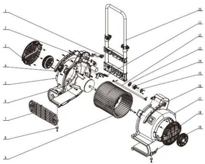
| ITEM PART DESCRIPTION | QTY | ||
| 1 | D1015003228 | Power cord | 1 |
| 2 | J1240440020 | Crimping board | 1 |
| 3 | Q7109145001 | Left wind window | 1 |
| 4 | Q7109105001 | Left handle | 1 |
| 5 | Q7109126158 | Left casing | 1 |
| 6 | 2982C229 | Motor assembly | 1 |
| ITEM PART DESCRIPTION | QTY | ||
| 7 | Q7109165001 | Outlet stencil | 1 |
| 8 | X6639220257 | Front foot pad | 2 |
| 9 | Q7109213001 | Multi-leaf fan | 1 |
| 10 | F4413701025 | Putt | 1 |
| J7022620411 | Catheter | 1 | |
| Q7109995001 | Pusher frame | 1 | |
| Q7106245001 | Pusher seat | 1 | |
| Q3766388001 | Left card holder | 1 | |
| Q3766378001 | Right card holder | 1 | |
| J3890570172 | Cam wrench | 2 | |
| Q3762988001 | Plastic washer | 2 | |
| J0200580003 | Spring | 2 | |
| Q3766398001 | Adjustment cap | 2 | |
| J0800470033 | Screw bolt | 2 | |
| Q3766408007 | Sleeve | 2 | |
| J220530033 | Pin nut | 2 | |
| J0782410032 | Screw M5×10 | 2 | |
| J0780600033 | Screw M8×8 | 2 | |
| 11 | Q7109983001 | Cable trough cover | 1 |
| 12 | J5882630081 | Roller shaft | 1 |
| 13 | Q6639185001 | Knob | 1 |
| 14 | Q6639195001 | Switch bracket | 1 |
| 15 | D3003000105 | Power switch | 1 |
| 16 | Q7109115001 | Right handle | 1 |
| 17 | Q7109136158 | Right casing | 1 |
| 18 | Q7109155001 | Right wind window | 1 |
| 19 | F4818401026 | Roller assembly | 2 |
| J1580870001 | Gasket | 2 | |
| J2840890021 | Cotter pin | 2 | |
| Q0001335001 | Decorative cover | 2 | |
Definitions: Safety Guidelines
The definitions below describe the level of severity for each signal word. Please read the manual and pay attention to these symbols.
ADANGER: Indicates an imminently hazardous situation which, if not avoided, will result in death or serious injury.
▲WARNING: Indicates a potentially hazardous situation which, if not avoided, could result in death or serious injury.
▲CAUTION: Indicates a potentially hazardous situation which, if not avoided, may result in minor or moderate injury.
NOTICE: Indicates a practice not related to personal injury which, if not avoided, may result in property damage.
IMPORTANT SAFETY INSTRUCTIONS
⚠ WARNING When using electric appliances, always follow basic safety precautions to reduce the risk of fire, electric shock and personal injury, including the following:
BEFORE USING THIS APPLIANCE, READ AND FOLLOW ALL INSTRUCTIONS.
⚠ WARNING: To reduce the risk of electric shock. Do not expose to rain. Store indoors.
- Do not leave the appliance when it is connected to a power source. Unplug it from outlet when not in use and before servicing.
- Do not allow the appliance to be used as a toy. Pay close attention when the appliance is used by or near children.
-
Use this appliance ONLY as described in the manual. Use only DEWALT recommended attachments.
-
Do not use this appliance with a damaged cord or plug. If the appliance is not working correctly, or if has been dropped, damaged, left outdoors, or dropped in water, return it to a service center.
- Do not pull or carry this appliance by the cord, use the cord as a handle, close a door on the cord, or pull the cord around sharp edges or corners. Do not run the appliance over the cord. Keep cord away from heated surfaces.
- Do not unplug this appliance by pulling on the cord. To unplug, grasp the plug, not the cord.
- Do not handle the plug or appliance with wet hands.
- Do not put any objects into the openings of the appliance. Do not use the appliance with any opening blocked; keep free of dust, lint, hair and anything else that may reduce air flow.
- Keep hair, loose clothing, fingers, and all body parts away from the openings and moving parts.
- Turn off all controls before unplugging appliance.
- Use extra care when using on or near stairs.
- If Air Mover is not working as it should, has missing parts, has been dropped, damaged, left outdoors, or dropped into water, call customer service.
- Do not run cord under carpeting. Do not cover cord with throw rugs, runners, or similar coverings. Do not route cord under furniture or appliances. Arrange cord away from traffic area and where it will not be tripped over.
▲ CAUTION: This appliance is not intended for use by persons (including children) with reduced physical, sensory or mental capabilities, or lack of experience and knowledge, unless they have been given supervision or instruction concerning use of the appliance by a person responsible for their safety.
Children should be supervised to ensure that they do not play with the appliance.
SAVE THESE INSTRUCTIONS
ADDITIONAL SAFETY RULES
- An extension cord must have adequate wire size (AWG or American Wire Gauge) for safety. The smaller the gauge number of the wire, the greater the capacity of the cable, that is 16 gauge has more capacity than 18 gauge. An undersized cord will cause a drop in line voltage resulting in loss of power and overheating. When using more than one extension to make up the total length, be sure each individual extension contains at least the minimum wire size. The following table shows the correct size to use. If in doubt, use the next heavier gauge. The smaller the gauge number, the heavier the cord.
| Minimum Gauge for Cord Sets | ||||||
| Ampere Rating | Volts | Total Length of Cord in Feet (meters) | ||||
| 120V | 25 (7.6) 50 | (15.2) 100 | (30.5) 150 | (45.7) | ||
| 240V | 50 (15.2) 1 | 00 (30.5) 2 | 00 (61.0) 3 | 00 (91.4) | ||
| More Than | Not More Than | AWG | ||||
| 0 6 | 18 16 | 16 | 14 | |||
| 6 | 10 | 18 | 16 | 14 | 12 | |
| 10 | 12 | 16 | 16 | 14 | 12 | |
| 12 | 16 | 14 12 | Not Recommended | |||
GROUNDING INSTRUCTIONS
This appliance must be grounded. If it should malfunction or breakdown, grounding provides a path of least resistance for electric current to reduce the risk of electric shock. This appliance is equipped with a cord having an equipment-grounding conductor and grounding plug. The plug must be inserted into an appropriate outlet that is properly installed and grounded in accordance with all local codes and ordinances.
This appliance is for use on a nominal 120-volt circuit, and has a grounded plug that looks like the plug illustrated in sketch A. A temporary adapter that looks like the adapter illustrated in sketches B and C may be used to connect this plug to a 2-pole receptacle as shown in sketch B if a properly grounded outlet is not available. The temporary adapter should be used only until a properly grounded outlet (sketch A) can be installed by a qualified electrician.
The green colored rigid ear, lug or the like extending from the adapter must be connected to a permanent ground such as a properly grounded outlet box cover. Whenever the adapter is used, it must be held in place by a metal screw.
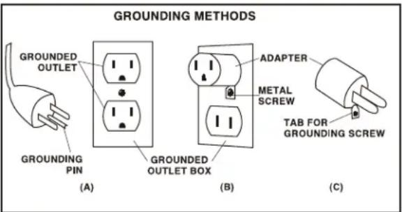
In Canada, the use of a temporary adapter is not permitted by the Canadian Electrical Code. Ensure that the air mover is connected to an outlet having the same configuration as the plug. No grounding adapter should be used with this appliance.
▲ WARNING: This product can expose to chemicals including lead, which is known to the State of California to cause cancer, birth defects or other reproductive harm. For more information go to www.P65Warnings.ca.gov.
WARNING:
- An extension cord must have adequate wire size for safety.
- When using more than one extension to make up the total length, be sure each individual extension contains at least the minimum wire size.
- Do not use to blow combustible explosive materials, such as coal, grain, or other finely divided combustible material.
- Never pick up explosive liquids (e.g. gasoline, diesel fuel, heating oil, paint thinner, etc.), acids or solvents.
- Some wood contains preservatives which can be toxic. Take extra care to prevent inhalation and skin contact when working with these materials. Request and follow any safety information available from the material supplier.
- Do not use air mover as a step ladder.
- Do not place heavy objects on air mover.
WARNING:
To reduce exposure to chemicals, wear approved safety equipment such as dust masks that are specially designed to filter out microscopic particles.
WARNING:
Do not point the air mover at other people or any living thing.
OPERATING INSTRUCTIONS
⚠ WARNING: TO REDUCE THE RISK OF FIRE OR ELECTRIC SHOCK, DO NOT USE THIS AIR MOVER WITH ANY SOLID-STATE SPEED CONTROL DEVICE.
Follow these instructions to operate the air mover:
- Unpack air mover from carton.
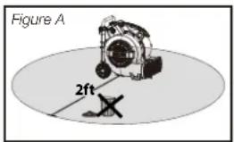
- To use unit, place the unit in the area most suitable for the application. Several factors need to be considered; the unit must be placed close enough to an AC outlet to be plugged in, there must be a minimum clearance of two feet from either side of the unit to allow for proper air flow, and the unit should not be placed where it can become a tripping or safety hazard.(see Figure A)
- Use only on a level and stable surface to prevent air mover from falling and possibly causing injury or damage to unit.
- Place unit in the proper operating position for application. Refer to the Operating Positions section in this manual.
- Plug unit into the wall.
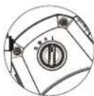
- Turn unit on and select air speed by turning the switch, located near the top handle, clockwise.
- When drying job is completed, turn the unit off and follow the directions for Storage in this manual.
Once the unit is plugged in, the air mover can be turned on by rotating the switch to one of the settings shown below.
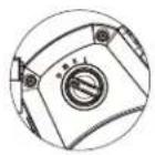
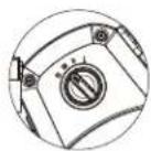

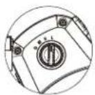
III (HIGH) II (MEDIUM) I (LOW) O (OFF)
AIR MOVER OPERATING POSITIONS
The air mover may be set in one of two operating positions. Pick the position best suited for the application.
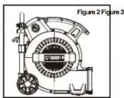
- Use the down position (Figure 2) for applications such as: drying wet floors, shampooed carpets, etc. To use this position simply place unit on its base.
- Use the up position for applications such as: drying paint on the ceiling. To use this position, lay the unit on the back side with the front grill pointing towards the ceiling (Figure 3).

natural_image
Technical line drawing of a mechanical device with no visible text or symbolsUNPACKING AND CHECKING CARTON CONTENTS
Carefully unpack and inspect Air Mover. Contact customer service if any parts are damaged or missing.
This Air Mover includes a retractable handle. It is shipped in its locked lowest position.
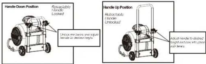
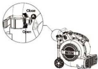
Tightening the Handle:
- If handle does not hold its position after engaging the lock levers, unlock the handle so adjustments can be made.
- Slightly tighten the hex nut (A) and re-engage the lock levers. If still not satisfactory, repeat this step until desired lock force is achieved. DO NOT OVERTIGHTEN.
STORAGE
CAUTION:
To clean the air mover, use a cloth dampened only with water and mild soap. Never let any liquid get inside the air mover. Never immerse any part of the air mover into a liquid.
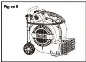
- Before storing air mover it should be cleaned.
- Wrap the power cord around the carry handle on the top of the unit to keep it untangled (Figure 5).
THE AIR MOVER SHOULD BE STORED INDOORS.
natural_image
Line drawing of a portable air purifier with wheels and fan (no text or symbols)CAUTION:
This Air mover is equipped with a motor thermal protection device. Once activated, it can restart without notice. If it is triggered, turn switch to OFF position, unplug unit and wait a moment before plugging air mover back in and restarting it.
TROUBLESHOOTING
⚠ WARNING:unplug before disassembly or servicing.
⚠ WARNING: All disassembly and repairs should be performed by qualified personnel.
Minor problems often can be fixed without calling customer service.
| PROBLEM SOLUTIONCAUSE | ||
| Unit will not run. | 1. No power to unit.2. Switch not on. | 1. Plug unit in. Check circuit breaker.2. Place in “ON” position. |
| Unit runs but Air Mover makes loud scraping noise. | 1. Unit has been severely jolted causing blower wheel to rub against housing or housing to deform. | 1. Contact customer service. |
| Unit runs but vibrates excessively. | 1. Dirt build up on one side of Air Mover blower wheel.2. Severe jolt has bent motor shaft. | 1. Contact customer service. |
| Unit runs but blower wheel does not turn. | 1. Blower wheel is jammed against housing. | 1. Contact customer service. |
| Unit runs briefly, then shuts off on overload. | 1. Intake grille and /or exhaust grille is obstructed.2. Motor bearings are failing or motor has developed an internal electrical fault. | 1. Remove obstruction.2. Contact customer service. |
▲ WARNING: If the supply cord is damaged, it must be replaced by the manufacturer, its service agent or similarly qualified persons in order to avoid a hazard.
WARRANTY
Alton Industry Ltd. Group 3 year Limited Warranty
This warranty covers any defects in materials or workmanship of the enclosed product. Alton Industry Ltd. Group will repair or replace any defectivematerials due to craftsmanship of the product. This warranty does not cover any problem caused by misuse, abuse, accidents or acts of God, such as floods or hurricanes. Consequential and incidental damages are not covered under this warranty. Coverage terminates if you sell or otherwise transfer the ownership. If you feel you have a defective product, please submit a copy of your receipt to the address below and call 1-888-899-0146 for instructions prior returning this item to the store or sending back to:
Alton Industry Ltd.Group
1031 North Raddant Rd
Batavia, Illinois 60510
We will inspect the product and contact you within 72 hours to give you the results of our inspection. We reserve the right to repair or replace the product at our discretion. However, we may replace the product with one of similar but not exact features. Parts and Service Information available call Alton Industry at 1-888-899-0146. This warranty gives you specific legal rights. You may have other rights which vary from state to state.
Copyright © 2019 DEWALT.
DEWALT ^® and the DEWALT Logo are trademarks of the DEWALT Industrial Tool Co., or an affiliate thereof and are used under license.
The yellow/black color scheme is a trademark for DEWALT power tools & accessories.
Copyright © 2019 DEWALT
Copyright © 2019 DEWALT.
III (ALTO) II (MEDIO) I (BAJO)O (OFF)
natural_image
Technical line drawing of a mechanical device with no visible text or symbols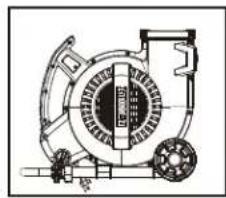
natural_image
Technical line drawing of a mechanical assembly with no visible text or symbolsnatural_image
Line drawing of a portable air conditioner unit with wheels and fan (no text or symbols)ADVERTENCIA:
Alton Industry Ltd. Group
1031 North Raddant Rd
Batavia, Illinois 60510
Copyright © 2019 DEWALT.
DEWALT® and the DEWALT Logo are trademarks of the DEWALT Industrial Tool Co., or an affiliate thereof and are used under license.
The yellow/black color scheme is a trademark for DEWALT power tools & accessories.
Copyright © 2019 DEWALT.
Copyright © 2019 DEWALT.
CARACTÉRISTIQUES DU PRODUIT
natural_image
Technical line drawing of a mechanical device with no visible text or symbolsDÉBALLER ET VÉRIFIER LE CONTENU DU CARTON
STOCKAGE
MISE EN GARDE:
natural_image
Line drawing of a mechanical device labeled 'Figure 5' with no visible text or symbols on the device itself.MISE EN GARDE:
Alton Industry Ltd. Group
1031 North Raddant Rd
Batavia, Illinois 60510
Copyright © 2019 D EWALT.
DEWALT® and the DEWALT Logo are trademarks of the DEWALT Industrial Tool Co., or an affiliate thereof and are used under license.
The yellow/black color scheme is a trademark for DEWALT power tools & accessories.
Copyright © 2019 D EWALT.
Copyright © 2019 D EWALT.