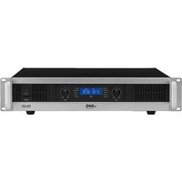
STA-225 - Receiver IMG Stageline - Free user manual and instructions
Find the device manual for free STA-225 IMG Stageline in PDF.


User questions about STA-225 IMG Stageline
0 question about this device. Answer the ones you know or ask your own.
Ask a new question about this device
Download the instructions for your Receiver in PDF format for free! Find your manual STA-225 - IMG Stageline and take your electronic device back in hand. On this page are published all the documents necessary for the use of your device. STA-225 by IMG Stageline.
USER MANUAL STA-225 IMG Stageline
These instructions are intended for users without any specific technical knowledge. The speakers, however, should only be connected by persons with the corresponding technical knowledge. Please read these instructions carefully prior to operating the unit and keep them for later reference.
All operating elements and connections described can be found on the fold-out page 3.
Contents
1 Operating Elements and Connections. 7
1.1 Front panel ..... 7
1.2 Rear panel 7
1.3 Display 7
2 Safety Notes 8
3 Applications....8
4 Setting up the Amplifier ..... 8
4.1 Rack installation 8
5 Connections....8
5.1 Inputs 8
5.2 Speakers 8
5.3 Power supply ..... 8
6 Operation 9
6.1 Selecting the operating mode ..... 9
6.2 Switching on/off 9
6.3 Adjusting the level ..... 9
6.4 Power indication 9
6.5 Groundlift switch ..... 9
7 Protective Circuits 9
8 Specifications 9
1 Operating Elements and Connections
1.1 Front panel
1 Volume controls one each for the channels L-CH and R-CH Note: In bridge mode, the control of the channel R-CH has no function.
2 Status LEDs one each for the channels L-CH and R-CH PROTECT lights up when the protective circuit separates the speaker from the amplifier: for a short time after switching-on and in case of overload /overheating of the amplifier LIMITER lights up when the limiter circuit is active and reduces the signal to prevent overload SIGNAL/−20dB/−10dB indicate the level of the output signal
3 LC display to show the operating parameters and status ( chapter 1.3)
4 Button LOAD 4/8 OHM to select the speaker load for the correct calculation of the power indication on the display (3) (if required, press several times)
5 Mains switch POWER
1.2 Rear panel
6 Inputs as XLR jacks
each for the channels L-CH and R-CH
Note: In bridge mode, the input of channel R-CH has no function.
7 Inputs as 6.3 mm jacks, balanced, for connection of a signal source with line level, one each for the channels L-CH and R-CH, alternatively to the XLR jack (6)
Note: In bridge mode, the input of the channel R-CH has no function.
8 Switch GROUNDLIFT to separate the signal ground from the housing ground: GROUND
signal ground and housing ground are connected
LIFT
signal ground and housing ground are separated (groundlift)
9 Switch MODE for selection of the operating mode STEREO/BRIDGE (chapter 6.1)
10 ON/OFF switch LIMITER for the automatic level limitation
11 Speaker outputs as screw terminals, alternatively to the speaker jacks (12 and 13)
12 Speaker jack R-CH
13 Speaker jack L-CH
14 Speaker jack BRIDGE for bridge mode
15 Mains jack for connection to a socket (230 V/50 Hz) via the supplied mains cable
16 Support for the mains fuse; only replace a blown fuse by one of the same type
1.3 Display
Standard indication during operation (fig. 3)
a output power of both outputs, calculated according to the output voltage measured and the load impedance selected [button LOAD 4/8OHM (4)]
Note: The calculation is not effective in bridge mode.
b CLIP ON/OFF for both outputs; if CLIP ON is shown, the amplifier input is overloaded. In this case, reduce the input level with the corresponding control (1).
c PROT ON/OFF (= PROTECTION, chapter 1.1, item 2, status LED PROTECT)
d temperature at the power transistors of both channels
e vertical bargraph indication for the output signals of both channels
Indication for a few seconds after actuating a volume control (1), the switch LIMITER (10) or the switch MODE (9) (fig. 4)
f STEREO/BRIDGE of the selected operating mode
g Status indication for the switch LIMITER (10) LIMT ON = limiter switched on LIMT OFF = limiter switched off
h ATTEN for attenuation of the input signals shows the position of the volume controls (1) numerically (i) and as a vertical bar (j)
Indication for a few seconds after actuating the button LOAD 4 / 8 OHM (4) (fig. 5)
k selected load impedance for the calculation of the output power shown (a)
2 Safety Notes
The unit corresponds to all relevant directives of the EU and is therefore marked with €€
WARNING

The unit is supplied with hazardous mains voltage. Leave servicing to skilled personnel only and do not insert anything into the air vents! In-expert handling may result in electric shock.
- The unit is suitable for indoor use only. Protect it against dripping water and splash water, high air humidity, and heat (admissible ambient temperature range 0 – 40 °C).
- Do not place any vessels filled with liquid, e. g. drinking glasses, on the unit.
- The heat being generated in the unit must be dissipated by air circulation. Never cover the air vents of the housing.
-
Do not set the unit into operation, and immediately disconnect the mains plug from the mains socket if
-
there is visible damage to the unit or to the mains cable,
- a defect might have occurred after a drop or similar accident,
- malfunctions occur.
The unit must in any case be repaired by skilled personnel.
- Never pull the mains cable to disconnect the mains plug from the mains socket, always seize the plug.
- For cleaning only use a dry, soft cloth, never use chemicals or water.
- No guarantee claims for the unit and no liability for any resulting personal damage or material damage will be accepted if the unit is used for other purposes than originally intended, if it is not correctly connected or operated, or if it is not repaired in an expert way.

If the unit is to be put out of operation definitively, take it to a local recycling plant for a disposal which will not be harmful to the environment.
3 Applications
This stereo PA amplifier is especially designed for applications on stage and in discotheques. It can be used in stereo mode or in mono bridge mode. Extensive protective circuits protect the amplifier and the speakers connected. Two powerful, temperature-controlled fans provide the necessary cooling of the amplifier.
4 Setting up the Amplifier
The amplifier is provided for insertion into a rack for units with a width of 482 mm (19"), but it can also be used as a tabletop unit. In each case, air must be allowed to flow freely through all air vents to ensure sufficient cooling of the amplifier.
4.1 Rack installation
For rack mounting, 2 RS (rack spaces) = 89 mm are required. Above the amplifier, one rack space should be left unused for air supply. The heated air blown out by the amplifier to the rear and to the sides must be able to dissipate from the rack, otherwise heat will accumulate in the rack which may not only damage the amplifier but also other units in the rack. In case of insufficient heat dissipation, insert a fan unit into the rack.
To prevent top-heaviness of the rack, the amplifier must be inserted in the lower part of the rack. To ensure a safe fixing, the front panel alone is not sufficient. In addition, the unit must be fastened at the rear side or be supported by means of lateral rails or a bottom plate.
5 Connections
Prior to connecting units or changing existing connections, switch off the amplifier and the units to be connected.
5.1 Inputs
Connect the output of a preamplifier or a mixer to the 6.3 mm jacks INPUTS (7) or the XLR jacks (6).
- The jacks are designed for balanced signals; the pin configuration is shown in fig. 2. For connection of sources with unbalanced signals, 2-pole 6.3mm plugs may be used or adapters with the XLR contacts 1 and 3 bridged.
- The input signal should have line level. For rated power of the amplifier, an input signal of 1.3V is required as a minimum.
- For bridge mode, only connect the input of the left channel L-CH.
- As the XLR jacks and the 6.3 mm jacks of the same input are directly connected, they can also be used for passing on the signal e. g. to an additional amplifier.
5.2 Speakers
The maximum output power is reached in stereo mode when connecting 4 Ω speakers (minimum admissible load impedance). It is also possible to connect 8 Ω speakers, however, in this case the output power will slightly be decreased. In bridge mode, the maximum output power will be reached with an 8 Ω speaker (minimum admissible load impedance in bridge mode). The required power rating (PMIN) of the speakers is listed in the table fig. 6.
For stereo mode, connect the speakers to the speaker jacks (12, 13), pin configuration of the plug see fig. 2, or to the screw terminals (11).
- After inserting a speaker plug into the jack, turn the plug clockwise until it engages. To remove the plug, retract the latch lock at the plug and turn the plug counter-clockwise.
- If the screw terminals are used, ensure that the cable ends are not stripped too far and that no bare wires protrude (hazard of contact and short circuit).
- When connecting the speakers, make sure that all speakers have the same polarity.
For bridge mode, connect the positive pole of the speaker to the positive terminal (11) of the left output L-CH and the negative pole of the speaker to the positive terminal of the right output R-CH (11). (By signal inversion in bridge mode, the positive terminal of the right output becomes the negative connection for the speaker.) The speaker can alternatively also be connected to the speaker jack BRIDGE (14) [pin configuration of the plug fig. 2].
Table fig. 6 also shows possibilities of connection for several speakers to one output. For each speaker, the minimum power rating ( P_MIN ) with the corresponding impedance (Z) is listed. When interconnecting several speakers, special attention has to be paid to the correct connection of the positive and negative terminals.
Important: The total impedance at each output must not fall below 4 Ω in stereo mode and must not fall below 8 Ω in bridge mode!
5.3 Power supply
Connect the mains cable to the mains jack (15) and the mains plug to a socket (230 V/ 50 Hz).
6 Operation
6.1 Selecting the operating mode
Select the desired operating mode STEREO / BRIDGE with the switch MODE (9).
Stereo mode - STEREO
In stereo mode, both channels are operated independently of each other.
Bridge mode - BRIDGE
The bridge mode is designed to obtain a higher power at a single speaker. For this purpose, both amplifier channels are combined to a mono amplifier: The input signal at the left channel is sent to the right channel additionally in an inverted way. Thus, the voltage at the output is doubled when the speaker is connected for bridge mode, as described in chapter 5.2. A signal at the right input is ignored. The volume is adjusted with the left control L-CH.
6.2 Switching on/off
To prevent loud switching noise, always switch on the power amplifier in an amplifier system after all other units and switch it off as the first unit after operation. Prior to switching on, turn the volume controls (1) to the left stop "MIN".
Switch on the amplifier with the switch POWER (5). After the welcome message, the display (3) shortly shows the adjustments of the operating mode, the limiter and the input attenuation (fig. 4) and then changes to the standard operating indication (fig. 3). After switching-on, the LEDs PROTECT (2) light up for a short time. During this time, the switch-on delay for the protection of the speakers is active.
6.3 Adjusting the level
Set the output of the mixer or preamplifier to its rated level (0 dB) or the highest undistorted output signal. Turn up the controls (1) until the maximum desired volume is reached. When the adjustment has been changed, the attenuation ATTEN of the input signal by the controls is shown on the display (3) both numerically (i) and graphically (j) for a few seconds. Then the display is changed to the standard indication again (fig. 3). The LEDs SIGNAL, -20 dB and -10 dB (2) and a vertical bar (e) on the display indicate the output level.
If the display shows CLIP ON, the input is overloaded. If the LIMITER LEDs light up, the limiter circuit is active and prevents an overload of the amplifier (Chapter 7). In both cases, turn back the corresponding control (1).
CAUTION Never adjust the amplifier to a very high volume. Permanent high volumes may damage your hearing! The human ear will get accustomed to high volumes which do not seem to be that high any more after some time. Therefore, do not further increase a high volume after getting used to it.
6.4 Power indication
The standard indication during operation (fig. 3) shows the output power of both speaker outputs in the first line (a). This value has been calculated according to the output voltage measured and a load impedance assumed. The specified load impedance is always 8 Ω after switching on the amplifier.
If 4 Ω speakers are connected, press the button LOAD 4 / 8 OHM (4) to adapt the calculation. The display now shows OUT 4Ω(k) and the power is calculated for a load impedance of 4 Ω. To switch back, press the button repeatedly until OUT 3Ω is shown. The display switches back to standard indication a few seconds after the last press of the button.
Note: The power indicated is not effective in bridge mode.
6.5 Groundlift switch
If an interfering hum noise can be heard without a music signal, a ground loop may be the reason for this. Ground loops may occur if two units have contact both via the signal ground and via the earthed conductor of the power supply or a conductive connection of the housings in the rack. To separate such a ground loop, set the switch GROUNDLIFT (8) to the position LIFT.
7 Protective Circuits
The protective circuits are provided to prevent damage to the speakers and the amplifier. The integrated level limiter reduces the input signal when the limit level is reached at the output. If the amplifier is overloaded, distortions can thus be prevented which could damage the speakers. With the switch LIMITER (10), this function can be switched on and off [indication LIMIT ON or LIMIT OFF(g)].
Due to an additional protective circuit, the speakers are separated from the output of the channel concerned. If it is active, the corresponding red PROTECT LED (2) lights up:
- for a short time after switching-on (switch-on delay)
- in case of overload / overheating, the indication PROT OFF (c) additionally changes to PROT ON on the display (3)
After cooling-down, the amplifier channel continues its operation.
In standard mode, the display shows the temperature at the power transistors separately for both channels (d). With higher temperatures, the fan control ensures that the fan of the channel concerned runs at higher speed.
If a PROTECT LED does not extinguish after switching-on or after cooling-down after an overload, the amplifier must be switched off and the cause for the defect must be eliminated.
8 Specifications
| RMS output power stereo at 4 Ω stereo at 8 Ω bridge mode at 8 Ω | 2 × 350 W2 × 250 W700 W |
| Input sensitivity for rated power at 8 Ω | 1.3 V |
| Input impedance | 10 kΩ |
| Frequency range | 10 Hz-50 kHz |
| THD Channel separation S/N ratio | < 0.1%>50 dB>80 dB |
| Connections Inputs Outputs | XLR and 6.3 mm jacks, balanced screw terminals and speaker jacks (Speakon compatible) |
| Ambient temperature | 0-40°C |
| Power supply Max. power consumption | 230V/50 Hz1500 VA |
| Dimensions (W×H×D) Rack spaces Weight | 482 × 100 × 330 mm2 RS10.3 kg |
Subject to technical modification.