MMX-8 - Mixer IMG Stageline - Free user manual and instructions
Find the device manual for free MMX-8 IMG Stageline in PDF.


User questions about MMX-8 IMG Stageline
0 question about this device. Answer the ones you know or ask your own.
Ask a new question about this device
Download the instructions for your Mixer in PDF format for free! Find your manual MMX-8 - IMG Stageline and take your electronic device back in hand. On this page are published all the documents necessary for the use of your device. MMX-8 by IMG Stageline.
USER MANUAL MMX-8 IMG Stageline
English ...... Page 8
Français....Page 12
Italiano ...... Pagina 16
text_image
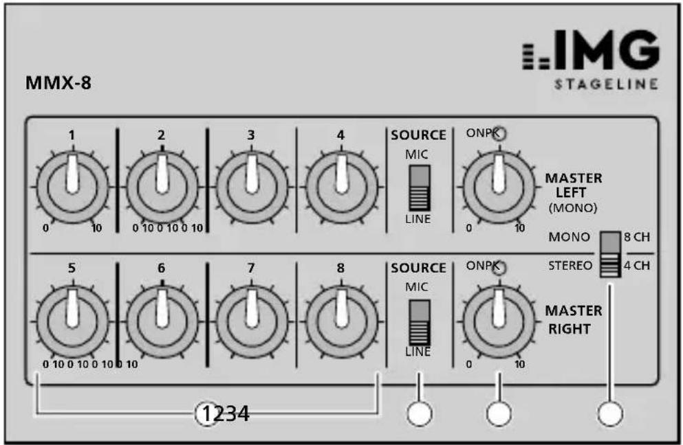
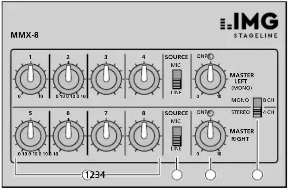
MMX-8 IMG STAGELINE 1 2 3 4 SOURCE MIC ONPK LINE MASTER LEFT (MONO) MONO 8 CH 4 CH 5 6 7 8 SOURCE MIC ONPK LINE STEREO MASTER RIGHT 0 10 0 10 0 10 0 10 1234These instructions are intended for users without any specific technical knowledge. Please read the instructions carefully prior to operation and keep them for later reference.
1 Operating Elements and Connections
1 Input controls
2 Selector switches for microphone / line inputs
3 Master controls with LED for the power LED and output level indication For mono operation, only the upper control is required.
4 Selectorswitch mono/stereo
5 ON/OFF switch
6 Jack for 9 V power supply
7 Outputs (6.3 mm jacks)
L (M) for mono operation
L + R for stereo operation
8 Inputs (6.3 mm jacks)
2 Important Notes
The unit corresponds to all relevant directives of the EU and is therefore marked with €€
- The unit is suitable for indoor use only. Protect it against dripping water and splash water, high air humidity, and heat (admissible ambient temperature range 0–40°C).
- For cleaning only use a dry, soft cloth, never use chemicals or water.
- No guarantee claims for the unit and no liability for any resulting personal damage or material damage will be accepted if the unit is used for other purposes than originally intended, if it is not correctly connected or operated, or not repaired in an expert way.
text_image
If the unit is to be put out of operation definitively, take it to a local recycling plant for a dis- posal which is not harmful to the environment.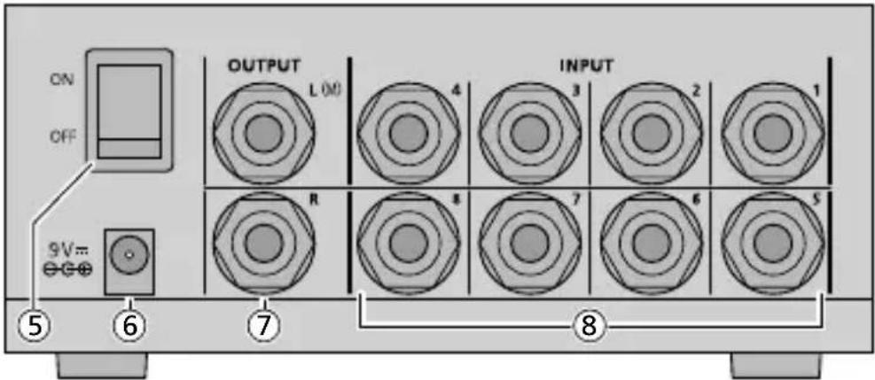
text_image
ON OFF 9V=- ⑤ ⑥ ⑦ INPUT ⑧ OUTPUT L(M) 4 3 2 1 R 8 7 6 53 Applications
The MMX-8 has especially been designed as a pre-mixer and allows connection of up to eight mono microphones or four stereo microphones. The inputs can be switched over to line level for connection of e. g. tuner, CD player and cassette recorder. The mixer is ideally suited e. g. for video dubbing or as a pre-mixer for microphone groups if there are not sufficient microphone inputs at the mixer or amplifier.
4 Power Supply
The power can be supplied via a 9 V battery or a 9 V power supply unit (e. g. PSS-600E from MONACOR).
1) The battery (not supplied with the unit) is inserted into the battery compartment at the lower side of the unit. For this purpose unscrew the battery compartment cover.
2) The power supply unit is connected to the jack 9 V= (6). Then an inserted battery is switched off. A low voltage plug 5.5/2.1mm(outside/insidediameter) is required. Always ob-
serve the correct polarity: The positive pole must be at the centre contact!
Attention! Replace exhausted batteries in time and remove the battery if the unit will not be used for a longer time. Thus, damage to the unit due to a leaking battery is prevented.

Never put batteries in the household waste. To protect the environment, always take them to a special waste disposal, e. g. collection container at your retailer.
5 Mono Operation
In mono operation up to 8 mono signal sources may be connected to the inputs (8).
1) The upper jack OUTPUT L (7) serves as an output. An amplifier or a recorder is connected to this jack. If microphones are connected to the mixer, the mixer has to be connected to the microphone input of the amplifier or recorder. The lower jack OUTPUT R is out of operation.
2) Set the selector switch MONO / STEREO (4) to MONO.
3) Select the type of signal source with the selector switches SOURCE (2):
$$ \mathrm{MIC} = \text { microphone } $$
$$ \begin{array}{c} \text {LINE = l ine input (tuner, CD,} \ \text {cassette)} \end{array} $$
4) To prevent switching noise, set both controls MASTER LEFT and MASTER RIGHT (3) to "0". Switch on the unit with the switch ON / OFF (5) on the rear side. First the LEDs ON PK above the controls shortly light up at maximum brightness and then continue to light at lower brightness.
5) Set the input controls (1) of the channels to which no unit has been connected to "0". Set the other controls to mid-position first.
6) Adjust the output level with the control MASTER LEFT (MONO) so that the following unit is adjusted to an optimum level.
7) Adjust the mixing ratio of the inputs with the input controls (1) accordingly. The LED ON PK above the control MASTER LEFT (MONO) serves as a level indicator. Correct the output level with the control MASTER LEFT (MONO), if required.
8) Individual channels are faded in and out with the corresponding input controls (1), if required. The output signal is faded in and out with the control MASTER LEFT (MONO).
6 Stereo Operation
In stereo operation up to 4 stereo signal sources may be connected to the inputs (8). The left channels are always connected to the upper jack and the right channels to the lower jack.
1) Connect an amplifier or a recorder to the jacks (7) OUTPUT L (left channel) and OUTPUT R (right channel). If microphones are connected to the mixer, the mixer must be connected to the microphone input of the amplifier or recorder.
2) Set the selector switch MONO / STEREO (4) to STEREO.
3) Select the type of signal source with the selector switches SOURCE (2):
$$ \mathrm{MIC} = \text { microphone } $$
$$ \begin{array}{c} \text {LINE = line input (tuner, CD,} \ \text {cassette)} \end{array} $$
Both selector switches SOURCE must be set to the same position.
4) To prevent switching noise, set both controls MASTER LEFT and MASTER RIGHT (3) to "0". Switch on the unit with the switch ON / OFF (5) on the rear side. First the LEDs ON PK above the controls shortly light up at maximum brightness and then continue to light at lower brightness.
5) Set the input controls (1) of the channels to which no unit has been connected to "0". Set the other controls to mid-position first.
6) Adjust the output level with the controls MASTER LEFT and MASTER RIGHT so that the following unit is adjusted to an optimum level.
7) Adjust the mixing ratio of the inputs with the input controls (1) accordingly. The LEDs ON PK above the controls MASTER LEFT and MASTER RIGHT indicate the output level. Correct the output level with the controls MASTER LEFT and MASTER RIGHT, if required.
8) Individual channels are faded in and out with the corresponding input controls (1), if required. The output signal is faded in and out with the controls MASTER LEFT and MASTER RIGHT.
7 Specifications
Inputs
MIC: 5 mV/10 kΩ
LINE: 50 mV/20 kΩ
Outputs: ..... 100 mV/2 kΩ
Frequency range:. . 20–20 000 Hz
THD: .... < 0.4 %
S/N ratio: ..... 55 dB
Power supply: .... 9 V=15 mA (battery or PSU)
Dimensions: ..... 150 × 115 × 68 mm
Weight: 700g
Subject to technical modification.
All rights reserved by MONACOR® INTERNATIONAL GmbH & Co. KG. No part of this instruction manual may be reproduced in any form or by any means for any commercial use.