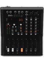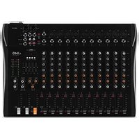
MXR-120 - Mixer IMG Stageline - Free user manual and instructions
Find the device manual for free MXR-120 IMG Stageline in PDF.


User questions about MXR-120 IMG Stageline
0 question about this device. Answer the ones you know or ask your own.
Ask a new question about this device
Download the instructions for your Mixer in PDF format for free! Find your manual MXR-120 - IMG Stageline and take your electronic device back in hand. On this page are published all the documents necessary for the use of your device. MXR-120 by IMG Stageline.
USER MANUAL MXR-120 IMG Stageline
English ..... Page 8
Français.....Page 12
text_image
MXR-60 MIC LINE 1 2 3 4 5/6 LINE L MONO B M L M R 3 PH. PW R +68 V 4 L USB 5/6 M L 5 M R 7 H. P. 8 AUX SEND 9 TAPE REC TAUX RET 10 GAIN MIN MAX H -15 dB +15 M -15 dB +15 L -15 dB +15 AUX MIN MAX -15 dB +15 FX MIN MAX PAN L R L R L R L R MIN MAX MIN MAX MIN MAX MIN MAX MIN MAX MIN MAX MIN MAX MAX 20 USB BT B 19 21 ▶ II REC ▶→→ MODE 22 100 400 1k 3k 6k Hz 30 23 DELAY REPEAT AUX SEND TAPE 31 MIN MAX MIN MAX MIN MAX MIN MAX 25 MIN MAX FX SEND AUX RETURN MIN MAXMIN MAX H. P. 15 PK 16 MUTE MUTE MUTE MUTE MUTE 17 1 2 3°4 5/6 FX M L^M R 18 PFL PFL PFL PFL PFL PFL PFL PFL PFL PFL PFL PFL PFL PFL PFL PFL PFL PFL PFL PFL PFL PFL PFL PFL PFL PFL PFL PFL PFL PFL PFL PFL PFL PFL PFL PFL PFL PFL PFL PFL PFL PFL PFL PFL PFL PFL PFL PFL PFL PFL PRL 26 29 10 10 10 10 10 10 10 10 10 10 10 10 10 10 10 10 10 10 10 10 10 10 10 10 10 10 10 10 10 10 10 10 10 10text_image
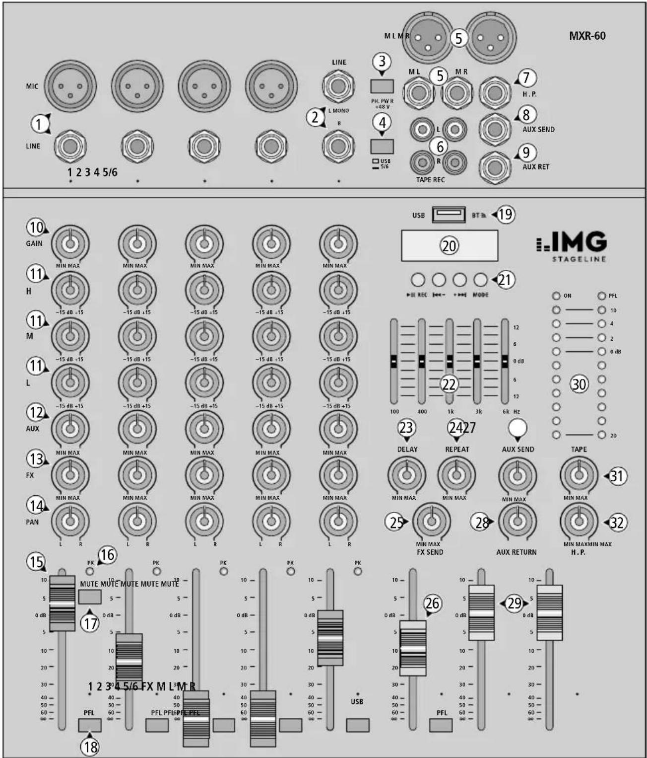
MXR-60 MIC LINE 1 2 3 4 5/6 LINE L MONO B M L M R 3 PH. PW R +68 V 4 USB 5/6 L L R TAPE REC 5 H. P. 7 AUX SEND 8 9 AUX RET 10 GAIN MIN MAX H -15 dB +15 M -15 dB +15 L -15 dB +15 AUX MIN MAX FX MIN MAX PAN L R L R L R L R MIN MAX MIN MAX MIN MAX MIN MAX MIN MAX MIN MAX MAX 20 USB BT B 19 21 ▶ II REC ▶→→ MODE 22 100 400 1k 3k 6k Hz 23 DELAY REPEAT AUX SEND TAPE 2427 30 MIN MAX MIN MAX MIN MAX MIN MAX FX SEND AUX RETURN MIN MAXMIN MAX H. P. 25 MIN MAX FX SEND 28 AUX RETURN 31 15 PK 16 MUTE MUTE MUTE MUTE MUTE 17 1 2 3°4 5/6 FX M L³MR 18 PFL PFL PFL PFL PFL PFL PFL PFL PFL PFL PFL PFL PFL PFL PFL PFL PFL PFL PFL PFL PFL PFL PFL PFL PFL PFL PFL PFL PFL PFL PFL PFL PFL PFL PFL PFL PFL PFL PFL PFL PFL PFL PFL PFL PFL PFL PFL PFL PFL PFL PRLRepresentation of MXR-60, models MXR-80/-120/-160 provide additional mono input channels
Audio mixer
These brief instructions give a quick overview of how to use the audio mixer. They are intended for users with basic knowledge of audio technology. Please read these instructions carefully prior to operating the unit and keep them for later reference.
1 Applications
This mixer can be used in many ways to mix audio signals (microphones, instruments, units with line level). The sum signal is output via the output jacks ML, MR (5), REC (6) and the USB port (19). The USB port is also used as an input for audio data when the mixer is connected to a computer and for the integrated audio player to replay MP3, WAV and WMA files from a USB flash drive. In addition, the audio player is equipped with a Bluetooth module.
2 Safety Notes
The mixer corresponds to all relevant directives of the EU and is therefore marked with €€.
WARNING
The unit uses dangerous mains voltage. Leave servicing to skilled personnel; inexpert handling may result in electric shock.
- The unit is suitable for indoor use only. Protect it against dripping water, splash water and high air humidity. The admissible ambient temperature range is 0–40°C.
- Do not place any vessel filled with liquid on the unit, e. g. a drinking glass.
-
Immediately disconnect the unit from the mains socket,
-
if the unit or the mains cable is visibly damaged,
- if a defect might have occurred after the unit was dropped or suffered a similar accident,
- if malfunctions occur.
In any case the unit must be repaired by skilled personnel.
- For cleaning only use a dry, soft cloth; never use water or chemicals.
- No guarantee claims for the unit and no liability for any resulting personal damage or material damage will be accepted if the unit is used for other purposes than originally intended, if it is not correctly connected or operated, or if it is not repaired in an expert way. Likewise, no liability will be accepted for data loss caused by a defect or operating errors and for any consequential damage of this data loss.

If the unit is to be put out of operation definitively, take it to a local recycling plant for a disposal which is not harmful to the environment.
2.1 Conformity and approval
Herewith, MONACOR INTERNATIONAL declare that the Bluetooth module in the units MXR-60, MXR-80, MXR-120 and MXR-160 complies with the directive 2014 / 53 / EU. The EU declarations of conformity are available on the Internet:
www.img-stageline.com
The Bluetooth module is generally approved for operation in EU and EFTA countries; it is licence-free and requires no registration.
3 Overview
The mains jack 230 V\~ / 50 Hz for connection to a mains socket and the POWER switch are located on the rear side of the unit.
1 Microphone input MIC (XLR jack) and input LINE (6.3 mm jack) for units with line level
2 Input LINE (6.3 mm jacks) of the stereo channel for units with line level
When connecting a mono unit, only use the jack L MONO. Thus, the signal will internally be routed to the right channel and the left channel.
3 On / Off switch PH.PWR of the 48 V phantom power supply for all XLR microphone inputs MIC (1)
Caution: Only use the switch when the mixer is switched off; otherwise, there may be loud switching noise.
4 Input selector switch:
Button engaged: input LINE (2)
Button disengaged: input USB port (19) or audio player with Bluetooth module
5 Stereo outputs M L, M R (XLR and 6.3 mm jacks) for the sum signal
6 RCA jacks for a recorder
At the output REC, the sum signal for the recordings is available [after the faders M L, MR (29)].
To add the signal available at the input TAPE to the sum signal, use the control TAPE (31).
7 Jack H. P. (headphones) for headphones
8 Output AUX SEND for the send way AUX
9 Input AUX RET to connect the output of an effect unit or of an additional Line audio source
10 Control GAIN for the input gain
11 Equalizer controls for the high frequencies (H), mid-frequencies (M) and low frequencies (L)
12 Control AUX to add the channel signal to the send way AUX; the signal will be routed to the send way after the channel fader (15)
13 Control FX to add the channel signal to the internal effect unit
14 Panorama control PAN to place the mono signal in the stereo sound, for the stereo channel, the control is used as a balance control
15 Channel fader for the volume of the channel
16 LED indicator PK: will light up briefly when the maximum undistorted signal level has been reached. If it lights up for a longer time,
the channel is overloaded; in this case, turn back the control GAIN (10).
When the button MUTE (17) is pressed, the LED indicator will light constantly.
17 Button MUTE to mute the channel; when the channel is muted, the LED indicator PK will light up
18 Button PFL for pre-fader listening of the channel by means of headphones connected to the jack H. P. (7); when the button is pressed, the top LED PFL of the LED indicators (30) will light up
19 USB port:
– output for digital sum signal
- input for audio data from the computer
- input for audio files from a USB flash drive to be replayed by means of the audio player
20 Display for the audio player
When the mixer is switched on, the display will briefly show the welcome message "HI"; when the USB port (19) is not connected, "no" will be shown on the display
21 Buttons for the audio player with Bluetooth module
Briefly press ▶II REC: to start / pause the replay; MP3 recording on a USB flash drive: to start, keep the button pressed until "rEC" is shown; to stop, press the button MODE
Briefly press I←←- +▶▶: previous/next title
Keep ◆◀- +▶▶ pressed: to adjust the volume
MODE: switch between
– replay (indication: "USb")
- Bluetooth reception ("bt")
22 5-band equalizer for the sum signal
23 Control DELAY for the effect delay time
24 Control REPEAT for the effect repeats
25 Control FX SEND to adjust the input level for the effect unit
26 Fader FX to add the internal effect signal to the output signal; if no effect is to be added, close the fader
27 Level control AUX SEND for the signal of the send way AUX that is available at the output AUX SEND (8)
28 Control AUX RETURN to add the input signal available at the jack AUX RET (9) to the sum signal, e.g. of an external effect unit or an additional Line audio source
29 Master faders for the output level of the sum signal available at the outputs ML, MR (5), REC (6) and the USB port (19)
30 Output level indicator and power indicator The LED indicator PFL will light up when one of the buttons PFL (18) is pressed
31 Control TAPE to add the signal available at the jack TAPE (6) to the sum signal
32 Volume control H. P. for the headphones
4 Quick Start
To avoid loud interfering noise, set the control H.P. (32) to MIN and close the master faders (29) prior to connection/disconnection and switch-on.
4.1 Connection
1) Connect the signal sources (microphones, instruments, etc.) to the input jacks (1, 2): Connect microphones to the XLR jacks MIC and units with line level to the 6.3 mm jacks LINE. When connecting signal sources to the input jacks LINE (2) of the stereo channel, press the input selector switch (4); when the USB port (19) or the audio player is used, make sure that the button is not pressed.
When using microphones that require phantom power supply, press the button PH. PWR (3); in all other cases, the button must not be pressed.
2) When a computer is used to replay audio files or for recordings, connect the computer to the USB port (19). An analog recorder can be connected to the RCA jacks (6) TAPE (input) and REC (output).
3) Connect the unit to which the sum signal is to be sent (amplifier, active speaker system) to the output jacks M L, M R (5). XLR jacks and 6.3 mm jacks are available that can be used at the same time.
4) Headphones to monitor the signal can be connected to the jack H. P. (7).
5) Use the mains cable provided to connect the mains jack 230V\~/50Hz located on the rear side of the unit to a mains socket (230V/50Hz).
4.2 Switching on the unit, mixing input signals
1) To make the basic adjustments, first
- set the controls GAIN (10), H, M, L (11) and PAN (14) to mid-position
- move the slider of the 5-band equalizer (22) to the mid-position 0 dB
- set the controls AUX (12), FX (13), AUX RETURN (28) and TAPE (31) to MIN
– close the channel faders (15) and the fader FX (26)
– disengage all buttons MUTE (17) and PFL (18)
2) Switch on the signal sources, then switch on the mixer by means of the POWER switch on the rear side of the unit and finally switch on the unit connected to the output jacks M L, M R (5). To switch off, proceed in the reverse order.
Move the master faders M L and M R (29) to the position 0 dB and mix the input signals by means of the channel faders (15).
If a channel fader must be advanced almost to its maximum, turn the control GAIN (10) to the right to increase the input gain. If, however, the LED indicator PK (16) lights up for a longer period of time, turn back the control accordingly. The LED indicator PK may only briefly flicker at signal peaks.
3) Use the panorama controls PAN (14) to distribute the channel signals on the stereo base as desired.
4) Use the controls H, M and L (11) to adjust the sound of the input signals. To adjust the sound of the sum signal, use the 5-band equalizer (22) which allows you to match the sound to the room acoustics, for example.
5) Use the master faders M L and M R (29) to adjust the sum signal for the subsequent unit to an optimum level. Use the control H. P. (32) to adjust the volume of the headphones (make sure that the volume is not too high; high volumes may damage your hearing!).
6) To mute a channel, e. g. during an interval, press the button MUTE (17). The LED PK (16) above the button will light up as an indication.
4.3 Pre-fader listening function PFL
Each audio source connected to the mixer and the effect signal of the internal effect unit can be monitored via headphones connected to the jack H. P. (7) even when the corresponding fader (15) or (26) is closed or the corresponding button MUTE (17) is pressed. Thus it is, for example, much easier to adjust the sound of each individual audio source.
1) To monitor an input channel, press the button PFL (18) of the corresponding channel: Instead of the sum signal, the channel signal selected can be heard via the headphones. The top right LED PFL of the LED indicators (30) will light up as an indication.
2) Press additional PFL buttons to monitor multiple input channels at the same time.
3) To listen to the sum signal again via the headphones, disengage all PFL buttons; the LED indicator PFL will extinguish.
4.4 Adding a delay effect
The internal effect unit can be used to create an adjustable delay effect from the signals of the input channels and to add this delay effect to the sum signal.
1) To make sure that the subsequent effect settings are audible, set the controls DELAY (23), REPEAT (24) and FX SEND (25) approx. to mid-position and move the fader FX (26) to the position 0 dB.
2) Use the control FX (13) to adjust the intensity of the effect for each channel signal separately. The signal for the effect unit will be picked up after the channel faders (15), i. e. the effect portion of a channel is always proportionate to the channel level adjusted.
3) Use the control DELAY (23) to adjust the effect delay time; use the control REPEAT (24) to define the number of repeats.
4) To increase or reduce the overall intensity of the effect, advance or close the fader FX (13) accordingly. For a further increase of the intensity, turn the control FX SEND (25) to the right; this control is used to adjust the input level of the effect unit. If distortions of the effect unit occur, turn back the control accordingly.
Subject to technical modification.
All rights reserved by MONACOR® INTERNATIONAL GmbH & Co. KG. No part of this instruction manual may be reproduced in any form or by any means for any commercial use.