BHCB93640BH - Basket BEKO - Free user manual and instructions
Find the device manual for free BHCB93640BH BEKO in PDF.

User questions about BHCB93640BH BEKO
0 question about this device. Answer the ones you know or ask your own.
Ask a new question about this device
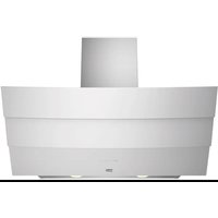
Download the instructions for your Basket in PDF format for free! Find your manual BHCB93640BH - BEKO and take your electronic device back in hand. On this page are published all the documents necessary for the use of your device. BHCB93640BH by BEKO.
USER MANUAL BHCB93640BH BEKO
natural_image
Simple line drawing of a kitchen range hood with three circular buttons (no text or symbols)BHCB 93640 B BHCB 93640 BH
EN DE FR ES BG BS KA NL PL PT RO SK SQ OZ

text_image
bekoPlease read this guide first!
Dear Customer,
Thank you for choosing a BEKO product. We would like you to achieve the optimal efficiency from this high quality product which has been manufactured with state of the art technology. Please make sure you read and understand this guide and supplementary documentation fully before use and keep it as a reference. Include this guide with the unit if you hand it over to someone else. Observe all warnings and information herein and follow the instructions.
Keep in mind that this user guide may apply to several product models. The guide clearly indicates any variations of different models.
Symbols and their meanings
These symbols are used throughout this guide:

Important information and recommendations regarding the use of the appliance.

CAUTION: Warnings on personal injury or property damage.
Electric shock warning,
Risk of fire warning.

This product has been manufactured at modern facilities respectful to the environment without harming nature.
CONTENTS
ENGLISH 04-16
DEUTSCH 17-34
FRANÇAIS 35-51
ESPAÑOL 52-70
БЪЛГАРСКИ 71-89
BOSANSKI 90-104
KARTULİ 105-124
NEDERLANDS 125-141
POLSKI 142-159
PORTUGUÊS 160-177
ROMÂNĂ 178-195
SLOVENSKÝ 196-210
SHQIPTARE 211-226
ČESKY 227-242
01M-8897303200-4120-08
01M-8897323200-4120-08
1 Important Safety and Environmental Instructions
1.1 General Safety
Important Safety Instructions Read Carefully And Keep For Future Reference This section contains safety instructions that will help protect from risk of fire, electric shock, exposure to leak microwave energy, personal injury or property damage. Failure to follow these instructions shall void any warranty.
- Beko products comply with the applicable safety standards; therefore, in case of any damage on the appliance or power cable, it should be repaired or replaced by the dealer, service center or a specialist and authorized service alike to avoid any danger. Faulty or unqualified repair work may be dangerous and cause risk to the user.
-
This appliance is intended to be used in household and similar applications such as:
-
Staff kitchen areas in shops, offices and other working environments;
- Farm houses
– By clients in hotels, and other residential type environments; - Bed and Breakfast type environments.
- Operate the appliance for its intended purpose only as described in this manual.
- The manufacturer cannot be held liable for damages resulting from improper installation or misuse of the product.
- This appliance can be used by children aged from 8 years and above and persons
with reduced physical, sensory or mental capabilities or lack of experience and knowledge if they have been given supervision or instruction concerning use of the appliance in a safe way and understand the hazards involved.
- Children shall not be allowed play with the appliance. Cleaning and user maintenance shall not be made by children without supervision.
- The minimum distance between the supporting surface for the cooking vessels on the hob and the lowest part of your product must be at least 65 cm.
- If the instructions for installation for the gas hob specify a greater distance, this has to be taken into account.
- Make sure that your mains power supply complies with the information supplied on the rating plate of the appliance.
- Never use the appliance if the power cable or the appliance itself is damaged.
- Prevent damage to the power cable by not squeezing, bending, or rubbing it on sharp edges. Keep the power cable away from hot surfaces and naked flame.
- Use the appliance with a grounded outlet only.
WARNING: Do not connect the appliance to the mains until the installation is fully complete.
- Place the appliance in a way so that the
1 Important Safety and Environmental Instructions
plug is always accessible.
- Do not touch the lamps if they have operated for a long time. They can burn your hands since they will be hot.
- Follow the regulations set out by competent authorities on discharge of the exhaust air (this warning is not applicable for use without Chimney).
- Operate your appliance after putting a pot, pan etc. on the hob. Otherwise, high heat may cause deformation in some parts of your product.
- Turn off the hob before taking the pot, pan etc. from it.
- Do not leave hot oil on the hob. Pans with hot oil may cause self combustion.
- Pay attention to your curtains and covers since oil may catch fire while cooking food such as fries.
- Grease filter must be replaced at least monthly. Carbon filter must be replaced at least every 3 months.
- Product shall be cleaned accordance with user manual. If cleaning was not carried out in accordance with user manual, there may be fire risk.
- Do not use non-fire-resistant filtering materials instead of the current filter.
- Only use the original parts or parts recommended by the manufacturer.
- Do not operate the product without the fil-
ter and do not remove the filters while the product is running.
- In the event of be started any flame, de-energize your product and cooking appliances.
- In the event of be started any flame, cover the flame and never use water to extinguish.
- Unplug the appliance before each cleaning and when the appliance is not in use.
- The negative pressure in the environment should not exceed 4 Pa (4 x 10 bar) while the hood for electric hob and appliances running on another type of energy but electricity operate simultaneously.
- In the environment where the appliance is being used, the exhaust of devices running on fuel oil or gas, such as room heater must be absolutely isolated or device must be hermetical type.
- When connecting the Chimney, use pipes with a diameter of 120 or 150mm . Pipe connection must be as short as possible and have as few elbows as possible.
Danger of choking! Keep all the packaging materials away from children.
CAUTION: Accessible parts may become hot when used with cooking appliances.
- The product outlet must not be connected to air channels that include other smoke.
- The ventilation in the room may be insufficient when the hood for electric hob is
1 Important Safety and Environmental Instructions
used simultaneously with the devices operating on gas or other fuels (this may not apply to appliances that only discharge the air back into the room).
- Objects placed on the product may fall. Do not place any objects on the product.
- Do not flambe under the your product.
WARNING: Before installing the Hood, remove the protective films.
- Never leave high naked flames under the hood when it is in operation
- Deep fat fryers must be continuously monitored during use: overheated oil can burst into flames.
1.2 Compliance with the WEEE Directive and Disposing of the Waste Product:
This product complies with EU WEEE Directive (2012/19/EU). This product bears a classification
symbol for waste electrical and electronic equipment (WEEE).
This symbol indicates that this product shall not be disposed with other household wastes at the end of its service life. Used device must be returned to official collection point for recycling of electrical and electronic devices. To find these collection systems please contact to your local authorities or retailer where the product was purchased. Each household performs important role
in recovering and recycling of old appliance. Appropriate disposal of used appliance helps prevent potential negative consequences for the environment and human health.
1.3 Compliance with RoHS Directive
The product you have purchased complies with EU RoHS Directive (2011/65/EU). It does not contain
harmful and prohibited materials specified in the Directive.
1.4 Package Information

Packaging materials of the product are manufactured from recyclable materials in accordance with our
National
Environment Regulations. Do not dispose of the packaging materials together with the domestic or other wastes. Take them to the packaging material collection points designated by the local authorities.
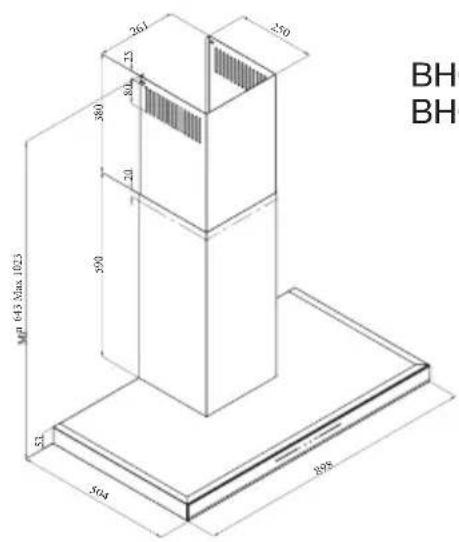
2 General Appearance
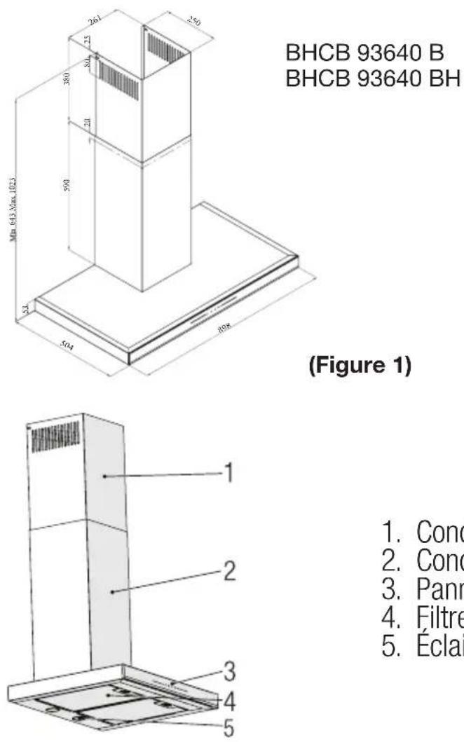
2.1 Overview
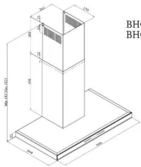
text_image
MP 643 Max.1023 504 898 250 261 75 80 20 900 52 BHC BHCBHCB 93640 B
BHCB 93640 BH
(Figure 1)

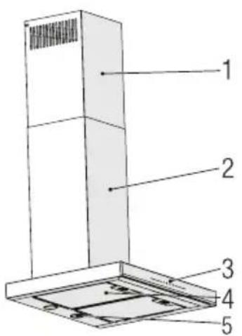
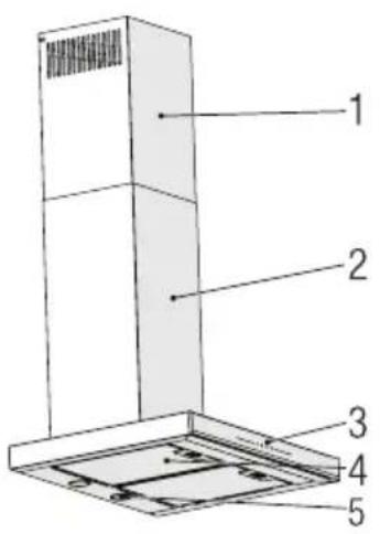
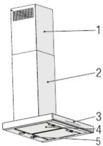
text_image
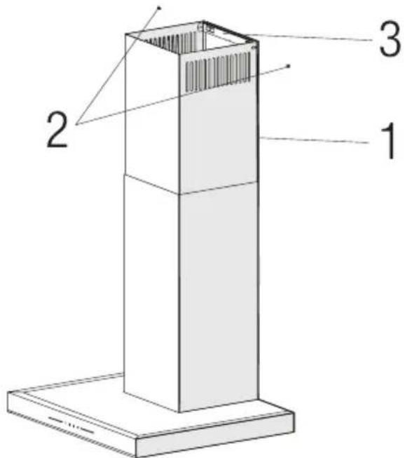
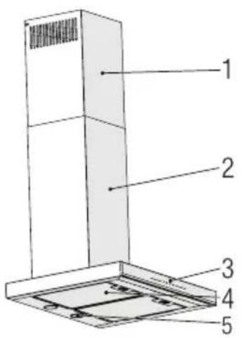
Technical diagram of a vertical-mounted air conditioner unit with numbered components labeled 1 through 5.- Inner Chimney
- Outer Chimney
- Control Panel
- Aluminum Grease Filter
- Lighting
(Figure 2)
2.2 Technical Data
| Model BHCB 93640 B - BHCB 93640 BH | |
| Supply voltage 220-240V ~ 50 Hz | |
| Lamp Power 2 x 3 W | |
| Motor Power 210 W | |
| Flow rate (m3/h) – 3. Level 645 m3/h | |
| Insulation Class of Motor Class F | |
| Insulation Class Class I | |
3 Operation of the Appliance
3.1 Controlling the Appliance


| KEY FUNCTION | |
| (A) : Light On / Off | You may illuminate the cooking area by pressing this button. Re-press the button to turn off the lamp. |
| (B) : 1. Stage Button | Operates the appliance on 1st speed. When you press this button again to turn off the appliance, the screen speed stage turns off. |
| (C) : 2. Stage Button | Operates the appliance on 2nd speed. When you press this button again to turn off the appliance, the screen speed stage turns off. |
| (D) : 3rd Stage Button | Operates the appliance on 3rd speed. When you press this button again to turn off the appliance, the screen speed stage turns off. |
3.2 Energy Efficient Usage
- When using your appliance, adjust the speed settings according to vapour and odour intensity, in order to save energy.
- Use low speeds (1-2) under normal conditions, and high speed (3) for intense odour and vapour.
- *The lamps on the hood are placed for illuminating the cooking area.
Using them for environmental lighting shall cause unnecessary energy expenditure and insufficient lighting.
3.3 Operating the Hood
- Your appliance contains a motor that has various speeds.
- For better performance, we recommend using low speeds under normal conditions and high speeds in cases of strong odours and intense vapour.
- You can start your appliance by pressing on the desired speed setting button. (A, B, C)
- You may illuminate the cooking area by pressing the lamp (D).
3.4 Automatic Stop
Your appliance has Automatic Stop feature, enabling it to ventilate for a bit more and remove the unwanted odours and vapour inside the environment and turn off automatically after the cooking is done. To enable Automatic Stop feature, press the any speed stage button (A, B, C) on the control panel for longer than 2 seconds; the 15-minute timer function shall be activated. When the automatic stop feature is active, pressing the same speed button shall disable the automatic stop function and the appliance's motor shall stop. This feature is disables when you switch between different speed stages. If you want the appliance to stop automatically, you need to enable the automatic stop feature again.
3 Operation of the Appliance
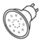
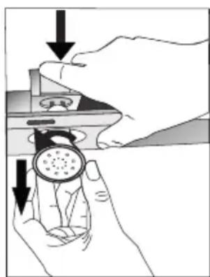
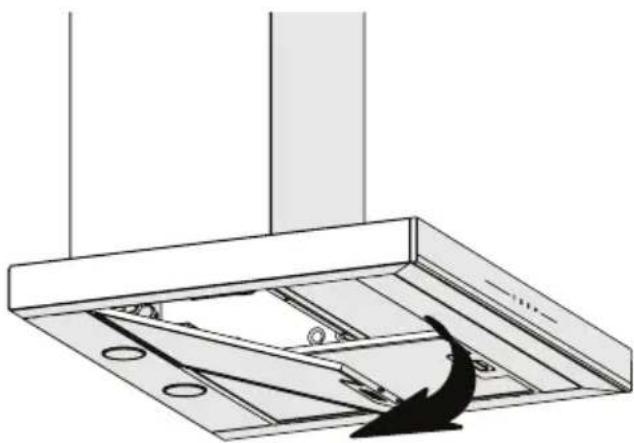
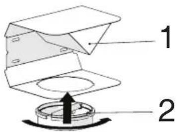
3.5 Replacement of Lamp
MAX 3 W
natural_image
Illustration of hands holding a device with a circular component and downward arrows indicating motion (no text or symbols)(Figure 3)
Make the electrical connections of the appliance. Your appliance uses 3W spot LED lamp. For replacing the lamps, push downwards on the holder from its behind, turn it counter-clockwise, and take it out downwards. Apply the above operation in reverse to install new lamps (Figure 3).
| Bulb | 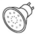 | |
| Bulb Power (W) 3 | ||
| Holder / Socket GZ 10 | ||
| Bulb Voltage (V) 220 - | 240 | |
| Size (mm) 53 x 50 | ||
| ILCOS Code DR/F3-22 | 0-240-GZ10-50-53 | |
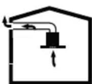
3.6 Operation with Chimney Connection
• Vapour is extracted through the flue duct, which is fastened to the connection head on the hood.
- The diameter of the flue duct must be the same as the connection ring. In horizontal settings, the pipe has to have a slight upward slope (around 10^ ) so that the air can exit the room easily.
3.7 Operation without Chimney Connection
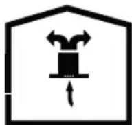
- Air is filtered through the carbon filter and recirculated in the room. Carbon filter is used when it is impossible to use a flue in the house.
- In flueless use, remove the flaps inside the flue adapter.
- Remove the aluminum grease filter. To install the carbon filter, fit the filter to the tabs by centring it on the plastic piece on both sides of the fan body. tighten it by turning right or left.
- Replace aluminum grease filter.
4 Cleaning and Maintenance

Before cleaning and maintenance, unplug the product or turn off the switch.
4.1 Cleaning of Aluminum Grease Filter
Aluminum grease filter is used to retain the oil particles in the air. Aluminum grease filter may change colour after repeated cleaning. This is normal, and you do not have to replace your filters.
natural_image
Technical diagram of a ceiling structure with mounting holes and a curved arrow indicating direction (no text or symbols)(Figure 4)
- Push the aluminum grease filter lock forward.
- Then pull it slightly down and pull it out (Figure 4). Otherwise, you may bend the filter. Wash and rinse aluminum grease filter with liquid detergent and replace aluminum grease filter to their seats by carrying out the steps specified above in reverse order. These aluminum grease filter are used to retain the oil particles in the air.

You may also wash the aluminum grease filter in the washing machine.

CAUTION
In case of normal use, clean your aluminum grease filter once in a month.
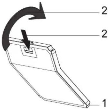
4.2 Replacement of Carbon Filters
text_image
2 2 1(Fig. 5)
The appliance you have purchased is appropriate for use with carbon filters.
- Remove the aluminum grease filter (Figure 4).
- Place the lower part of the carbon filter to the motor cabinet (Figure 5).
- Press on the tab of the carbon filter and push it forward, and ensure that the tabs of carbon filter are engaged and locked. (Figure 5).
- Attach the aluminum grease filter.

CAUTION
Carbon filter shall never be washed.

CAUTION
Replace carbon filters once every 3 months.

CAUTION
You can obtain the carbon filter from the authorized services.
5
Installation Of Appliance

WARNING!
Before starting the installation, read the safety information on User Manual.

WARNING!
Failure to install with screws and stabilizers in accordance with these instructions may result in electric shock.
For the installation of the hood, please contact the nearest Authorized Service.
It is the customer's responsibility to prepare the location and electrical installation of the hood.
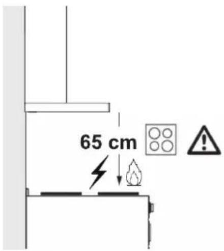
5.1 Position of the Appliance
text_image
65 cm(Figure 6)
- Distance between the cooker and the cooker hood must be considered prior to assembly. This distance should be 65 cm (Figure 6).
- Distance must be measured from the surface of grate for gas cookers,
• from surface of glass for electric cookers.
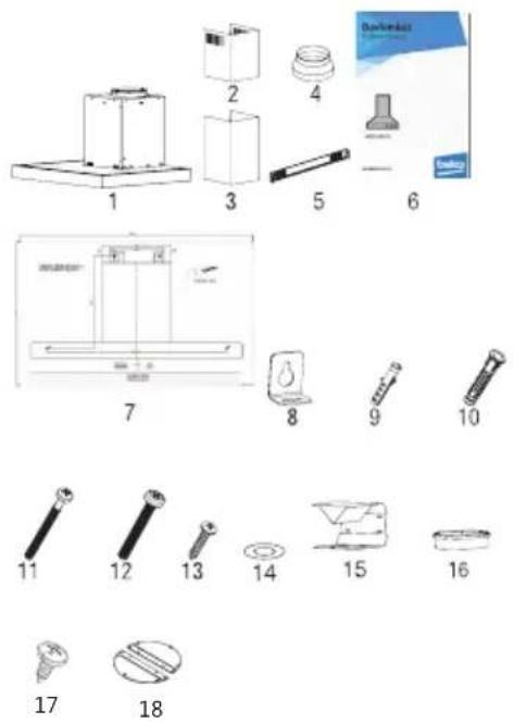
5.2 Installation Accessories
text_image
Technical diagram showing exploded view and assembled views of 18 mechanical parts with numbered labels- Product
- Inner Chimney
- Outer Chimney
- ∅150/120 mm Plastic Flue Adapter
- Chimney Connection Plate
- User Manual
- Assembly Pattern
- 2x Hanging Plates
- 2x ∅6mm Plastic Dowel
- 4x ∅10mm Plastic Dowel
- 4x 5.5x60 Wall Mount Screw
- 2x M5x35 Hanging Plate Connection Screw
- 2x 3.9x22 Chimney Connection Plate Screw
- 2x M4 Washer
- Air Baffle
- Plastic Adapter (Air Diverter)
- 2x 3.5x9.5 Chimney Connection Plate Screw
- Chimney Clamp
The information required to make the location suitable for the installation of the hood is given below.
5 Installation Of Appliance
5.3 Wall Mounting
- Wall must be flat, straight and have the sufficient bearing capacity.
- Depth of drilling holes must comply with the length of bolts.
- The bolts and dowels provided are suitable for brick walls. For other construction material (e.g. drywall, plate, porous concrete), suitable fixing dowels and nuts shall be used.
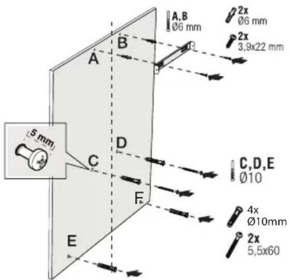
text_image
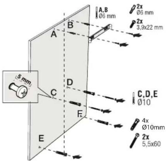
A,B Ø6 mm 2x Ø6 mm 2x 3,9x22 mm 5 mm A B C,D,E Ø10 4x Ø10mm 2x 5,5x60 E(Figure 7)
CAUTION
Before drilling, ensure that there are no power, gas or water pipes in the close proximity of the drilling locations.
Draw a mid location line from the ceiling perpendicular to the lower edge of the hood ().
Fix the assembly scheme on the wall. For points A and B, take the maximum dimensions of the hood as reference, and drill points A and B you have marked with a ∅6mm drill bit, and tap ∅6mm plastic wall plugs. Install the chimney connection plate to the wall with 2 pieces of 3.9x22 screws (Figure 8).
To install the hood body, drill points C,D,E ,F specified in the installation template with a ∅10mm drill bit and tap ∅10mm plastic dowels to these points (Figure 8).
Install 2 pieces of 5.5x60 mounting screws to points C and D with a clearance of 5 mm between the screw head and the wall (Figure 8).
text_image
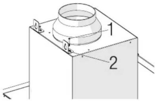
Technical diagram of a mechanical component with labeled parts 1 and 2(Figure 8)
Install two pieces of hanging plates to the body of the hood with M5x35 mounting screws (Figure 8).
natural_image
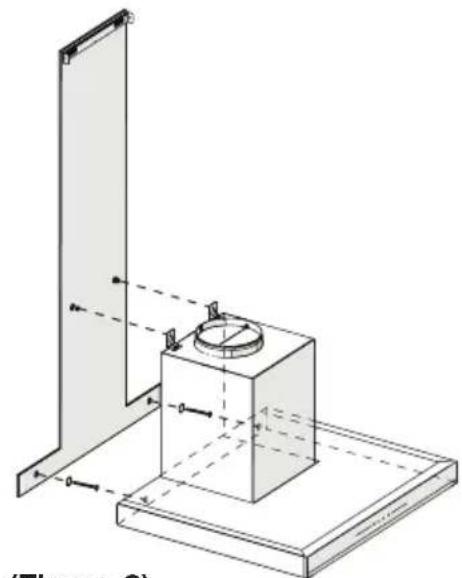
Technical line drawing of a mechanical assembly with a central component and support structure (no text or symbols)(Figure 9)
5 Installation Of Appliance
Hold the cooker hood by its body and place it on the mounting screws on the wall and tighten the screws (Figure 9).
Install M4 washers to the 5.5x60 suspension screws. Secure the cooker hood with 5.5x60 screws to the wall through the mounting hole on the interior of the appliance (Figure 9).
5.4 Connecting to Chimney
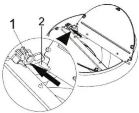
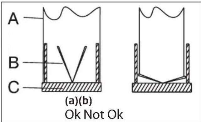
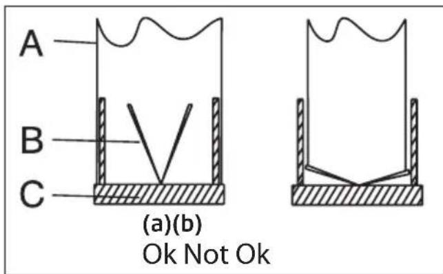
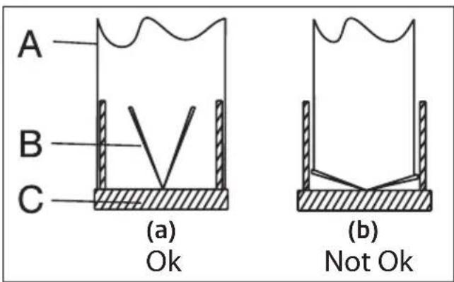
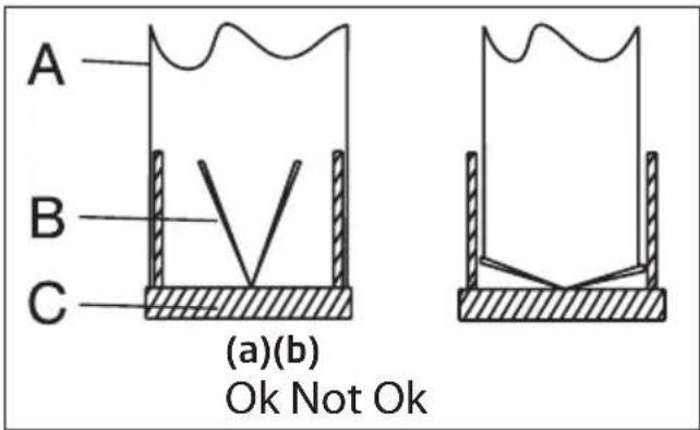
If you are going to use the ∅ 120/150 mm plastic Chimney adapter, connect one end of the pipe to this adapter, if you are not going to use it, to the direct output on the product. Connect the other end of the pipe to your Chimney . Check that these two connections are tight enough so they will not come out when the appliance runs on full power. Check if the flaps inside the Chimney operate when they are tightened
with clamps. Connect the Chimney connection duct outside the adapter (Figure 11/a). If the connection duct is fitted inside the adapter, suction of air shall not occur as the Chimney flap that prevents the return of air will remain closed (Figure 11 / b). The length of the pipe connection as well as the number of elbows must be as minimum as possible.
A: Chimney exit pipe
B : Non return flaps
C: Plastic flue
The valves are closed then the appliance is not operating and prevent possible outside odour and dust from entering inside.
text_image
Technical diagram showing mechanical assembly with labeled parts 1 and 2, including a magnified inset view of internal components.(Figure 10)
text_image
A B C (a)(b) Ok Not Ok(Figure 11)
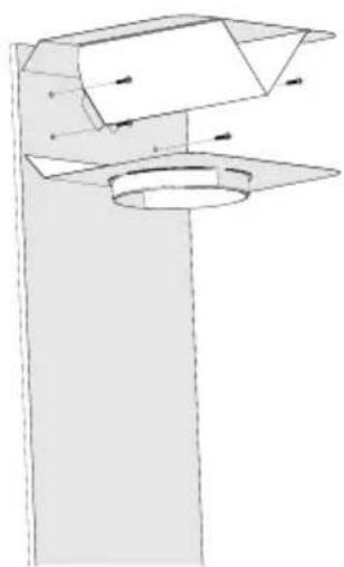
5.5 Installation of the Hood to the Chimney
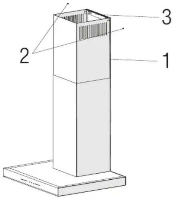
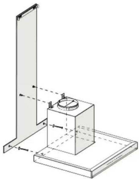
Make the electrical connection of your hood before starting the installation of the Chimney. Slip the Chimney plates around the body. Install the Chimney plate to the Chimney fastening plate that is secured to the wall from its upper outer edges (Figure 12).
text_image
Technical diagram of a vertical structural component with numbered parts labeled 1, 2, and 3.(Figure 12)
- Inner Chimney
- 3.5×9.5 Screw
- Chimney Connection Plate
5 Installation Of Appliance
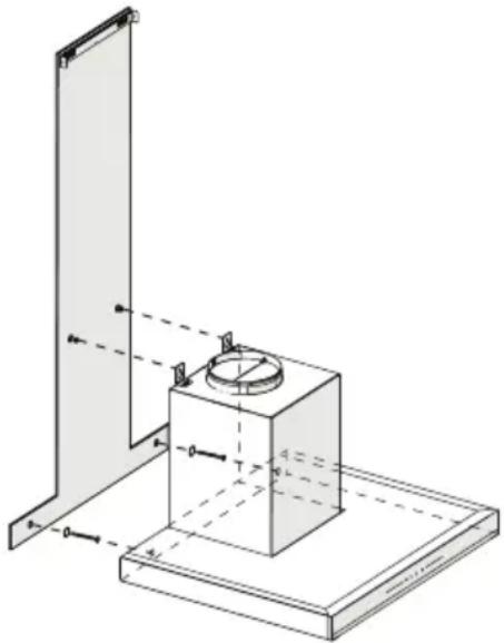
5.6 Installation of Air Baffle (BHCB 93640 BH)
While using with the carbon filter, air baffle is provided with your appliance with the aim of re-releasing the air which is cleaned with carbon filter from the perforated located on the Chimney. Assemble the air baffle as below.

text_image
39.50mm 188mm 46.50mm Ø6mm 160mm A B C D E F B D F 6x Ø6mm 2x Ø 3,9 x 22 mm(Fig. 13)
There is a tab in the middle of the Chimney connection plate. Place the middle point of this tab on the line that is drawn perpendicular to the wall. Align horizontally and mark the holes where the connection plate will be mounted via a pen (Figure 13 / A, B).
Drill the marked points with ∅6mm drill and insert two ∅6mm plastic dowels in the drilled holes (Figure 13 / A, B).
Fix the Chimney connection plate to the wall with 3.9x22 screws (Figure 13/A, B).
For air baffle assembly, install point C, D, E, F with ∅6mm drill and ∅6mm plastic dowels (Figure 13).
text_image
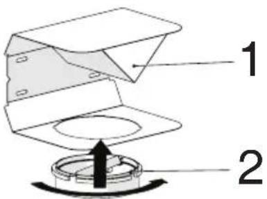
Diagram of a device with labeled parts, showing a component with parts numbered 1 and 2.(Fig. 14)
1 - Air Baffle
2- Plastic Chimney
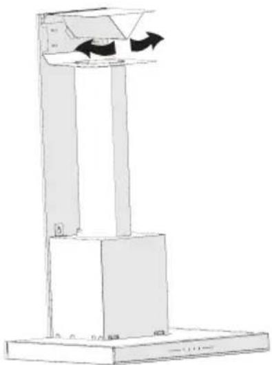
Attach the plastic Chimney adapter, which is included in the package, in the direction of the air baffle. Lock the Chimney adapter by turning it in the direction of the arrow (Figure 14).
natural_image
Technical line drawing of a mechanical assembly with no visible text or symbols(Figure 15)
Assemble the air baffle group with 3.9 x 22 screws from point C, D, E, F that you have already prepared (Figure 13).
Assemble the hood body (Page 12 / Figure 7).
5 Installation Of Appliance
natural_image
Diagram of a vertical stand with arrows indicating direction, no text or symbols present(Fig. 16)
1 - Aluminium Air Outlet Pipe Make the air outlet pipe assembly (Figure 16).

Since twists and bends in the aluminium pipe will lead to reduction in the air suction power, avoid using twists and bends as much as possible.
Install the Chimney plates of the hood (Page 13 / Figure 12)
6 Troubleshooting
| Troubleshooting Root Cause Help | ||
| Appliance is not working. | Check your fuses. Fuse may be blown, inspect and restore it. | |
| Appliance is not working. | Check the electrical connection. Mains voltage shall be between 220 and 240 V. | |
| Appliance is not working. | Check the electrical connection. Check if other appliance in your kitchen operate. | |
| Illumination light does not operate. | Check the electrical connection. Mains voltage shall be between 220 and 240 V. | |
| Illumination light does not operate. | Inspect the lamp switch. Lamp switch shall be at "on" position. | |
| Illumination light does not operate. | Inspect the lamps. The lamps of the appliance shall illuminate. | |
| Air inlet of the appli-ance is inadequate. | Inspect the aluminium filter. Under normal operating conditions, aluminum grease filter shall be cleaned at least once in a month. | |
| Air inlet of the appli-ance is inadequate. | Check the air discharge chimney . The air discharge chimney shall be at "on" position. | |
| Air inlet of the appli-ance is inadequate. | Inspect the carbon filter. The filters of the appliances with carbon filters shall be replaced once in every 3 months under normal conditions. | |
BHCB 93640 B
BHCB 93640 BH
(Abbildung 1)
text_image
Technical diagram of a vertical-mounted air conditioner unit with numbered components labeled 1 through 5.natural_image
Technical line drawing of a ceiling structure with ventilation grilles and a downward arrow indicating airflow or movement (no text or symbols)(Abbildung 4)
text_image
Technical diagram showing 18 labeled mechanical components with numbered parts and exploded viewstext_image
Technical diagram of a mechanical component with labeled parts 1 and 2(Abbildung 8)
natural_image
Technical line drawing of a mechanical assembly with a central component and support structure (no text or symbols)(Abbildung 9)
text_image
Technical diagram showing mechanical assembly with labeled parts and a magnified inset view of a component detail.(Abbildung 10)

text_image
A B C (a)(b) Ok Not Ok(Abbildung 11)
natural_image
Technical line drawing of a mechanical assembly with no visible text or symbols(Abbildung 14)
natural_image
Diagram of a vertical stand with arrows indicating direction, no text or symbols present(Abb. 16)
BHCB 93640 B
BHCB 93640 BH
natural_image
Technical diagram of a ceiling structure with ventilation ducts and a black arrow indicating airflow direction (no text or symbols)(Figure 4)
text_image
Technical diagram showing exploded view and assembled parts of a mechanical assembly, labeled with numbers 1 through 18.text_image
Technical diagram of a mechanical component with labeled parts 1 and 2(Figure 8)
natural_image
Technical line drawing of a mechanical assembly with a cylindrical component mounted on a base plate (no text or symbols)(Figure 9)
text_image
1 2 (Figure)(Figure 10)

text_image
A B C (a)(b) Ok Not Ok(Figure 11)
For air baffle assembly, install point C, D, E, F with ∅6mm drill and ∅6mm plastic dowels (Figure 13).
text_image
1 2(Fig. 14)
natural_image
Technical line drawing of a mechanical assembly with no visible text or symbols(Figure 15)
natural_image
Diagram of a vertical stand with arrows indicating direction, no text or symbols present(Fig. 16)
BHCB 93640 B
BHCB 93640 BH
(Imagen 1)

text_image
1 2 3 4 5natural_image
Technical diagram of a ceiling structure with an arrow indicating direction (no text or symbols present)
PRECAUCIÓN
text_image
Technical diagram showing exploded view and assembly of 18 mechanical parts with numbered labelstext_image
Technical diagram of a mechanical component with labeled parts 1 and 2(Imagen 8)
natural_image
Technical line drawing of a mechanical assembly with a central component and mounting base (no text or symbols)(Imagen 9)
text_image
Technical diagram showing mechanical assembly with labeled parts 1 and 2, including directional arrows and structural components.(Imagen 10)
text_image
A B C (a)(b) Ok Not Ok(Imagen 11)
natural_image
Technical line drawing of a mechanical assembly with no visible text or symbols(Imagen 15)
natural_image
Diagram of a vertical stand with arrows indicating direction, no text or symbols present(Imagen 16)
text_image
Diagram of a vertical-mounted air conditioner unit with numbered components labeled 1 through 5natural_image
Illustration of hands holding a device with arrows indicating process flow (no text or symbols)(Фигура 3)
natural_image
Technical diagram of a ceiling structure with mounting holes and a curved arrow indicating direction (no text or symbols)(Фигура 4)
text_image
Technical diagram showing 18 labeled mechanical components with numbered parts and assembly viewstext_image
Technical diagram of a mechanical component with labeled parts 1 and 2(Фигура 8)
natural_image
Technical line drawing of a mechanical assembly with a central component and mounting base (no text or symbols)(Фигура 9)
text_image
Technical diagram showing mechanical assembly with labeled parts 1 and 2, including a magnified inset view of internal components.(Фигура 10)

text_image
A B C (a)(b) Ok Not Ok(Фигура 11)
natural_image
Technical line drawing of a mechanical component with no visible text or symbols(Фигура 15)
natural_image
Diagram of a vertical stand with arrows indicating motion or force direction, no text or symbols present(Фиг. 16)
BHCB 93640 B
BHCB 93640 BH
(Slika 1)
text_image
Technical diagram of a vertical shelf or chimney with numbered components labeled 1 through 5natural_image
Illustration of hands holding a device with a circular component and arrows indicating motion (no text or symbols)(Slika 3)
natural_image
Technical line drawing of a ceiling structure with ventilation grilles and a downward arrow indicating airflow or movement (no text or symbols)(Slika 4)
- Gurnite bravu aluminijskog filtra za masnoću prema naprijed.
- Zatim je lagano povucite prema dolje i izvucite je (Slika 4). U suprotnom možete saviti filtar. Operite i isperite aluminijske filtre za masnoću tečnim deterdžentom i vratite alumijske filtre za masnoću na njihova mjesta izvodeći gore navedene korake obrnutim redoslijedom. Ovi aluminijski filtri za masnoću koriste se za zadržavanje čestica masnoće u zraku.

text_image
Technical diagram showing exploded view and assembly of 18 mechanical parts with numbered labels- Proizvod
- Unutarnji dimnjak
- Vanjski dimnjak
- ∅150/120mm adapter za dimnjak
- Ploča za priključak na dimnjak
- Uputstvo za upotrebu
- Obrazac montaže
- 2x viseće ploče
- 2x ∅6mm plastični klip
- 4x ∅10mm plastični klip
- 4x 5,5x60 vijak za zidnu montažu
- 2x M5x35 vijak za pričvršćivanje viseće ploče
- 2x 3,9x22 vijak za ploču za priključak na dimnjak
- 2x podloške M4
- Zračna pregrada
- Plastični adapter (diverter zraka)
- 2x vijak pločice za priključak dimnjak 3,5x9,5
- Stezaljka za dimnjak
Informacije potrebne za pripremu lokacije prikladne za postavljanje aspiratora date su u nastavku.
5 Ugradnja uređaja
5.3 Montaža na zid
- Zid mora biti ravan, prav i imati dovoljnu nosivost.
- Dubina rupa za bušenje mora biti u skladu s dužinom vijka.
- Isporučeni vijci i klipovi prikladni su za zidove od opeke. Za drugi građevinski materijal (npr. gipsani zid, ploča, porozni beton) koriste se odgovarajući učvrsni klipovi i matice.
text_image
A,B Ø6 mm 2x Ø6 mm 2x 3,9x22 mm 5 mm A B C,D,E Ø10 4x Ø10mm 2x 5,5x60 E F(Slika 7)

OPREZ
Prije bušenja osigurajte da u neposrednoj blizini mjesta bušenja nema struje, plina ili vode.
text_image
Technical diagram of a mechanical component with labeled parts 1 and 2(Slika 8)
Ugradite dva komada visećih ploča na kućište aspiratora pomoću montažnih vijaka M5x35 (Slika 8).
natural_image
Technical line drawing of a mechanical assembly with a cylindrical component mounted on a base plate (no text or symbols)(Slika 9)
5 Ugradnja uređaja
Držite aspirator za štednjak za njegovo kućište i stavite ga na montažne vijke na židu i pritegnite vijke (Slika 9).
Ugradite podloške M4 na vijke na kačenje 5,5x60. Pričvrstite aspirator za štednjak s vijkom 5,5x60 na zid kroz otvor za montažu s unutarnje strane uređaja (Slika 9).
text_image
Technical diagram showing mechanical assembly with labeled parts 1 and 2, including a magnified inset view.(Slika 10)

text_image
A B C (a)(b) Ok Not Ok(Slika 11)
5.5 Ugradnja aspiratora na dimnjak
text_image
Technical diagram of a vertical structural component with numbered parts labeled 1, 2, and 3.(Slika 12)
natural_image
Technical line drawing of a mechanical component with no visible text or symbols(Slika 15)
Sastavite grupu zračnih pregrada s vijcima 3,9 x 22 iz točke C, D, E, F koju ste već pripremili (Slika 13).
Montirajte kućište aspiratora (Strana 12/ Slika 7).
5 Ugradnja uređaja

natural_image
Diagram of a vertical stand with arrows indicating direction, no text or symbols present(Slika 16)
z m g s m m b d s m g g m,
1.1 6m3s00 ylsg6m6m8ds
∂δο∂ʒδρμm3s6o
ஏமுக்குவெ
yusgmoebmgdssobsb
ωςζσζδομγδοσ -
yghsqngdoo fsozombon
ως όροδειση οὐ
m3g6s30g8ds 3g0d4m7ds
zsdm0h3omu hol3o qos
საცრიხე შეუქმნას
∂m∂b∂s∂g∂g∂v.
• 360000000
śmòu żśbżgózmżbomo
3mədʒmboŋmo
gsdmggbdolomzou, ogo
gsb3gm3bomos lsbcmdo
ως άγδωγδ 3οήμαγδο
zsdmbsygbjdmsq:
- ∂σμσθογδού,
mgolgdois qos lb3s
სამუშაო სიკრცეების
3gmbsmolozou
856390360m
სამზარეულოში;
- სოცლის სახლმი;
- სასტუმროები,
∂m∂g∂g∂dσ δδ
lsbs lsgbm3mgdgm
mǎoqājāqāqā;
- 3mU0GmV0Dn 5b dU2s3v
Assymado.
• ζσδμογχβση
∂mθγμδομμδs ∂bμμμω
sd lsbgcmddm3sbgmmdo
S###
qubdghgdoisdgh.
∂mhymdommds
gymdθmgtugmoqsb
ωs sm zshdobqmm
∂mhymdommds dolo
zsdmygbjduu qomlu.
- grades of the design of the design of the design of the design of the design of the design of the design of the design of the design of the design of the design of the design of the design of the design of the design of the design of the design of the design of the design of the design of the design of the design of the design of the design of the design of the design of the design of the design of the design of the design of the design of the design of the design of the design
- 10
- 36mmqyj80msb
gmo l03m3gdo
gs66g sb mb3sq
ls53s36g dmdyds3g
dmhymdommdgdo,
hmgmmo2ss monsbou
zsdsmdmdgmo,
l6mymssq y6qos oymu
o6mmo6gddgmo
36mmqyj80u gsdmusd3gdo
domo2gsb sb y6qos oymu
3gmdg80mno.
- 36mmqngjgolmzou
33sdmlsmbou
dggmogdou dmygmodus
gsdmoygbou 150 dd
sb 120 dd qosdgfou
djmbg domgdo. doomou
2 6m3s0o 8s6g8b7mo ls6g
2.1 άοδμβομης
text_image
261 250 804 380 70 290 52 504 898 Mn 643 Max.1023 BHC BHCBHCB 93640 B BHCB 93640 BH
(6sbs8o 1).

text_image
Diagram of a vertical shelf with numbered components, likely an appliance or equipment assembly- ὁρος 33δμυσόνο
- Assig 33səməsənbo
- მართვის პანელი
- མབྱོདབཞ དབཟན བྱི་མོལ་པུང་
- நூம்ப் செயையேற்று
(6sbsQo 2)
2.2 ཅඩිජාංංංංංංංංංංංංංංංංංංංංංංංංංංංංංංංංංංංංංංංංංංංංංංංංංංඳ
| ∂mργμο | BHCB 93640 B - BHCB 93640 BH |
| ∂mργμο ∂mργμο ∂sδ3s | 220-240V ~ 50 Hz |
| ⊥sδsμο ∂o∂dms36ŋ (30) | 2 x 3 W |
| ∂mσzο ∂o∂dms36ŋ (30) | 210 W |
| δsδsμο ∂oβjs6ŋ (∂3/ 10) - 3. ρm6ŋ | 645 m3/h |
| ∂mσzο ∂θmmszο ∂3msbo | 3msbo F |
| ∂θmmszο ∂3msbo | 3msbo I |
| ###s30 ###b30s | |
| (A) : ###s80s b60s / ###m8s | sd ###s30s ###f60m ##zodmssn h60mss ###s80s, ###gmo gssbsngdu f##sl. lssbsnls ###s80s ###s80m ###s30s. |
| (B) : 1. ###b ###s30 | dm#ymdoomdou s439ds 1-mo lohjs60m. dm#ymdoomdou s4mls60s5q sd ###s30s ###dgm60m ###s80s lohjs60s ###s80s ###m639ds. |
| (C) : 2. ###b ###s30 | dm#ymdoomdou s439ds 3-2 lohjs60m. dm#ymdoomdou s4mls60s5q sd ###s30s ###dgm60m ###s80s lohjs60s ###s80s ###m639ds. |
| (D) : 3 ###b ###s30 | dm#ymdoomdou s439ds 3-3 lohjs60m. dm#ymdoomdou s4mls60s5q sd ###s30s ###dgm60m ###s80s lohjs60s ###s80s ###m639ds. |
3.2 gradesgradesgrades gradesgradesgrades gradesgradesgrades gradesgradesgrades
natural_image
Technical line drawing of a ceiling structure with mounting holes and ventilation duct (no text or symbols)(6s6s8o 4)
g_3g_2m_0b_0m_1g_1d_1 g_3g_2m_0b_0m_1g_1d_1 g_3g_2m_0b_0m_1g_1d_1 g_3g_2m_0b_0m_1g_1d_1

zsgmmbomgd bsbdoou g0mGn dggodmosm dgodobmn s3mno bj8y lghzolbj6gmdo.
5
text_image
Technical diagram showing 18 labeled mechanical components with numbered parts and assembly views- 36mqyj80
- მიდა კვამლსარინი
- გარე კვამლსარინი
- ∅150/120 ∂∂ 33∂μυσόοδού σροςθόμο
- 33sđmısımобол მემაცოთებელი 3sნელი
- əmədbəsɪŋɡdʒənʊl ɪsɒɡməddəŋʒsɒɡm
- sbsfymdou 0030
- 2x ὅglɔʒoŋo 3s6gɔ̱o
- 2x ∅6 ∂∂ 3πλυδαλού ρωγδημο
- 4x ∅10 ∂∂ 3msl§dslou ωογδγωο
- 4x 5.5x60 3900000 lsdsz600 b6s660
- 2x M5x35 ἄγλυσορο δεδημού ἀγγκόνδου ὑδυδο
- 2x 3.9x22 33sədəməsəməbəʊ əgədʒɡməŋgədʒməʊ 3səbʒməʊl bɔːsbɔo
- 2x M4 ἀμνδυσχογδο
- 3sŋmʊb sədʒɔʒm
- 3amshydsou sqsszgno (3sgnob lsmobo)
- 2x3.5x9.5 33sdmlsqgbo dsgmogjmo 6glscgjdoubfsbbo
18. 33sdmlsqgbou qnoombou dmdfgo
text_image
Technical diagram of a mechanical component with labeled parts 1 and 2(6sbs8o 8)
ωssyghgym mho 35mo əŋbʒoqno 35bŋmo ʒʌdʒmʒol ʒmʒŋlɪŋ M5x35 lsʌdmβgɔjym bɔnsbβdɔom (bsbsʒo 8).
natural_image
Technical line drawing of a mechanical assembly with a central circular component and two vertical supports (no text or symbols)(6sbs8o 9)
qosfomgou gsdfmzo 3mmbuon qos gsbsmszugm 3jogmbg qosdmbgsggggmc lsdmbgsgm bmsbbgdbg, dgdqgg dmmyfomgou bmsbbgdu (bsbsgo 9).
qssygbom M4 dysusqgdo 5.5x60 ls3oqmo b6sbbbg. qssdsgm gsdgmzo zjgwmbg 5.5x60 b6sbbom dmhymdommdou docos dbsmju smlgdymno lsdmbgsym bsbzgmol dgdzgmdoon (bsbsgo 9).
5
text_image
Technical diagram showing mechanical assembly with labeled parts 1 and 2, including directional arrows and structural elements.(6s6s8o 10)
text_image
A B C (a) Ok (b) Not Ok(6sbs8o 11)
5.5 3s46m30u qsdmb8s98s 33s4m15m6b6g
33sdmlsmbolu dmbsgolu qshygsdqng zsdsmogon gmygdym ddgmogdydo. 33sdmlsmbolu 3sbgmgoz sqqssqzoqng 3mmbgolu zsmdgm. qssdmbsggn 33sdmlsmbolu 3sbgmo lsdsgh 3sbgmgy, hmdgmo qsdsgmgymos 3qggmgy bqos zsmy 3oqolu dbsmgl (bsbsgo 12).
text_image
Technical diagram of a vertical structural component with numbered parts labeled 1, 2, and 3.(6sbs8o 12)
natural_image
Technical line drawing of a mechanical assembly with no visible text or symbols(6sbs8o 15)
ωssyghom 3sgmol sdmgzmol dmmmz0 3.9 x 22 bhsbbgdom dmdbscgjdym fghgmoqgdoo C, D, E, F (bbsgo 13). ωssyghom 3sdgmzol 3mmbzylo (83gmoo 12 / bsbsgo 7).
5
∂m§γμδομπδού ∂m§θση

natural_image
Diagram of a vertical stand with arrows indicating motion or force direction, no text or symbols present(65b. 16)
1- 3sgnol zsdmddʒgdo smydaobou doqmo
qssyj6gm 3sgmou zsdmdd3gdo domo (bbs8o 16).

οδοῦ ὅσδm, ἡμαὶ ςμνγόδοῦν ὁσμοῦ ∂μεγβ̃s ὅσδοῦν̃323υ 3ṣμοῦ ὁσβμοῦ υοδαμοῦν ὁσδοῦν̃γδυ, ∂σβιοῦν̃σμνγήσω ὅσχωμ σὐ δαμμύροῦ ὁσμοῦ.
BHCB 93640 B
BHCB 93640 BH
(Afbeelding 1)

text_image
Technical diagram of a vertical tower with numbered components for identificationnatural_image
Technical diagram of a ceiling structure with mounting holes and ventilation ducts (no text or symbols)(Afbeelding 4)
text_image
Technical diagram of a mechanical component with labeled parts 1 and 2(Afbeelding 8)
natural_image
Technical line drawing of a mechanical assembly with a cylindrical component mounted on a base plate (no text or symbols)(Afbeelding 9)
text_image
Technical diagram of a vertical structural component with numbered parts labeled 1, 2, and 3.(Afbeelding 12)
text_image
39,50mm 188mm 46,50mm Ø6mm 160mm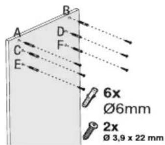
text_image
A B C D F E 6x Ø6mm 2x Ø 3,9 x 22 mm(Afb. 13)
natural_image
Technical line drawing of a mechanical assembly with no visible text or symbols(Afbeelding 15)
natural_image
Simple line drawing of a vertical platform with arrows indicating rotation or movement (no text or symbols)(Afb. 16)
BHCB 93640 B
BHCB 93640 BH
(Rys. 1)

text_image
Technical diagram of a vertical-mounted air conditioner unit with numbered components labeled 1 through 5.natural_image
Illustration of hands holding a device with a circular component, showing mechanical components and directional arrows (no text or symbols)(Rys. 3)
natural_image
Technical line drawing of a ceiling structure with mounting holes and a curved arrow indicating direction (no text or symbols)(Rys. 4)
text_image
Technical diagram showing 18 labeled mechanical components with numbered parts and assembly viewsnatural_image
Technical line drawing of a mechanical assembly with a central component and support structure (no text or symbols)(Rys. 9)
text_image
1 2 (Rvs)(Rys. 10)

text_image
A B C (a)(b) Ok Not Ok(Rys. 11)
natural_image
Technical line drawing of a mechanical component with no visible text or symbols(Rys. 15)
natural_image
Diagram of a vertical stand with arrows indicating direction, no text or symbols present(Rys. 16)
BHCB 93640 B
BHCB 93640 BH
(Figura 1)

text_image
Technical diagram of a vertical-mounted air conditioner unit with numbered components labeled 1 through 5.natural_image
Technical diagram of a ceiling structure with an arrow indicating direction (no text or symbols present)(Figura 4)
natural_image
Technical line drawing of a mechanical assembly with a cylindrical component mounted on a base plate (no text or symbols)(Figura 9)
natural_image
Technical line drawing of a mechanical component with no visible text or symbols(Figura 15)
natural_image
Diagram of a vertical stand with arrows indicating direction, no text or symbols present(Fig. 16)
BHCB 93640 B
BHCB 93640 BH
(Figura 1)
text_image
Technical diagram of a vertical shelf or chimney with numbered components labeled 1 through 5- Tub de evacuare intern
- Tub de evacuare extern
- Panou de control
- Filtre de ulei din aluminiu
- Sistem de iluminare
(Figura 2)
2.2 Date tehnice
natural_image
Illustration of hands holding a device with a circular component, showing mechanical adjustment (no text or symbols)(Figura 3)
natural_image
Technical diagram of a ceiling structure with ventilation grilles and a downward arrow indicating airflow or movement (no text or symbols)(Figura 4)
text_image
Technical diagram showing exploded view and assembled views of mechanical components with numbered partstext_image
Technical diagram of a mechanical component with labeled parts 1 and 2(Figura 8)
natural_image
Technical line drawing of a mechanical assembly with a central component and mounting base (no text or symbols)(Figura 9)
5
text_image
39.50mm 188mm 46.50mm Ø6mm 160mm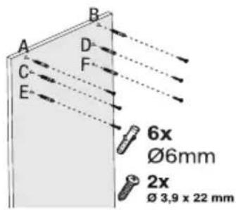
text_image
A B C D E F 6x Ø6mm 2x Ø 3,9 x 22 mm(Fig. 13)
natural_image
Technical line drawing of a mechanical assembly with no visible text or symbolsnatural_image
Diagram of a vertical stand with arrows indicating motion or force direction, no text or symbols present(Fig. 16)
text_image
Technical diagram of a vertical tower with numbered components for identificationnatural_image
Illustration of hands holding a device with a circular component, showing mechanical components and directional arrows (no text or symbols)(Obrázok č. 3)
natural_image
Technical diagram of a ceiling structure with an arrow indicating direction (no text or symbols present)(Obrázok č. 4)
text_image
Technical diagram showing exploded view and assembly of 18 mechanical parts with numbered labelstext_image
Technical diagram of a mechanical component with labeled parts 1 and 2(Obrázok č. 8)
natural_image
Technical line drawing of a mechanical assembly with a central component and support structure (no text or symbols)(Obrázok č. 9)
5
natural_image
Technical line drawing of a mechanical component with no visible text or symbols(Obrázok č. 15)
natural_image
Diagram of a vertical stand with arrows indicating direction, no text or symbols present(Obr. č. 16)
BHCB 93640 B
BHCB 93640 BH
(Figura 1).
text_image
Diagram of a server rack with numbered components for identificationnatural_image
Illustration of hands holding a device with a circular component, showing mechanical adjustment (no text or symbols)(Figura 3)
natural_image
Technical diagram of a ceiling structure with ventilation ducts and a downward arrow indicating airflow or movement (no text or symbols)(Figura 4)
text_image
Technical diagram showing exploded view and assembled parts of a battery pack with numbered labelsnatural_image
Technical line drawing of a mechanical assembly with a cylindrical component mounted on a base plate (no text or symbols)(Figura 9)
text_image
Technical diagram showing mechanical assembly with labeled parts 1 and 2, including directional arrows indicating motion or force.(Figura 10)
text_image
A B C (a)(b) Ok Not Ok(Figura 11)
5.5 Montimi i aspiratorit me oxhakun
natural_image
Technical line drawing of a mechanical assembly with no visible text or symbols(Figura 15)
natural_image
Diagram of a vertical stand with arrows indicating direction, no text or symbols present(Fig. 16)
natural_image
Illustration of hands using a tool to adjust a circular component with arrows indicating motion (no text or symbols)(Obrázek č. 3)
natural_image
Technical diagram of a ceiling structure with ventilation ducts and a downward arrow indicating airflow or movement (no text or symbols)(Obrázek č. 4)
text_image
Technical diagram showing exploded view and assembly of 18 mechanical parts with numbered labelstext_image
Technical diagram of a mechanical component with labeled parts 1 and 2(Obrázek č. 8)
natural_image
Technical line drawing of a mechanical assembly with a central component and support structure (no text or symbols)(Obrázek č. 9)
text_image
Technical diagram showing mechanical assembly with labeled parts and a magnified inset view of a component detail.(Obrázek č. 10)

text_image
A B C (a)(b) Ok Not Ok(Obrázek č. 11)
text_image
Technical diagram of a vertical structural component with numbered parts labeled 1, 2, and 3.(Obrázek č. 12)
natural_image
Technical line drawing of a mechanical assembly with no visible text or symbols(Obrázek č. 15)
natural_image
Diagram of a vertical stand with arrows indicating motion or force direction, no text or symbols present(Obr. č. 16)