BWS 400-2 - Saw ATIKA - Free user manual and instructions
Find the device manual for free BWS 400-2 ATIKA in PDF.

| Product Type | Tilting circular saw for firewood |
| Brand | ATIKA |
| Model | BWS 400-2 |
| Dimensions (L x W x H) | 1002 x 737 x 1046 mm |
| Weight | 38.3 kg |
| Supply voltage | 230 V ~ |
| Mains frequency | 50 Hz |
| Mains fuse | 16 A delay |
| Motor power (S2 15 min) | 2.2 kW |
| Protection type | IP 54 |
| Idle speed | 2800 min⁻¹ |
| Saw blade (diameter) | 405 mm |
| Blade bore | 30 mm |
| Number of blade teeth | 32 |
| Cutting diameter | 30 mm (min) to 140 mm (max) |
| Allowable wood length | 300 mm (min) to 1000 mm (max) |
| Sound power level (L_WA) | 115 dB(A) |
| Sound pressure level (L_PA) | 96 dB(A) |
| Motor brake | Integrated, stop < 10 s |
| Motor protection circuit breaker | Yes, with automatic reset after cooling |
| Intended use | Cross-cutting firewood (outdoor only) |
| Maintenance and cleaning | Clean with brush or vacuum, biodegradable oil for moving parts, no water |
| Warranty | According to supplied warranty declaration |
| Spare parts | Blade, plastic inserts, return spring, etc. – use of original parts recommended |
Frequently Asked Questions - BWS 400-2 ATIKA
User questions about BWS 400-2 ATIKA
0 question about this device. Answer the ones you know or ask your own.
Ask a new question about this device
Download the instructions for your Saw in PDF format for free! Find your manual BWS 400-2 - ATIKA and take your electronic device back in hand. On this page are published all the documents necessary for the use of your device. BWS 400-2 by ATIKA.
USER MANUAL BWS 400-2 ATIKA
Original instructions
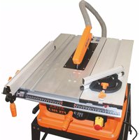
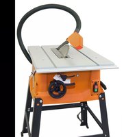
Log saw
Notice originale
Do not operate machine before having read the operating instructions, understood all the notes and assembly the machine as described here.
Keep the instructions in a safe place for future use.
Contents
| Declaration of conformity 11 | |
| Extent of delivery 11 | |
| Characteristics noise values 11 | |
| Operating times 11 | |
| Symbols: operating manual 11 | |
| machine 12 | |
| Normal intended use 12 | |
| Residual risks 12 | |
| Safety working 12 | |
| Description of device / Spare parts 14 | |
| Assembling 14 | |
| Before the first start-up 15 | |
| Start-up 15 | |
| Working with the saw 16 | |
| Maintenance and cleaning 16 | |
| - Changing the saw blade 17 | |
| - Replacing the plastics insert 17 | |
| - Replacing the recuperating spring 17 | |
| Transport 17 | |
| Storage 17 | |
| Guarantee 17 | |
| Possible faults 18 | |
| Technical data 18 |
EC Declaration of Conformity
No. (S-No.): 27778
according to EC directive 2006/42/EC
We,
Altrad Lescha Atika GmbH
Josef-Drexler-Str. 8, 89331 Burgau - Germany
herewith declare under our sole responsibility that the product
Brennholzwippkreissäge (Log saw) BWS 400-2
Serial number: 000001 - 020000
is conform with the above mentioned EC directives as well as with the provisions of the guidelines below:
2014/30/EU and 2011/65/EU.
Following harmonized standards have been applied:
EN 1870-6:2017; EN 60204-1:2006+A1; EN 55014-1:2006+A1+A2;
EN 55014-2:1997+A1+A2; EN 61000-3-2:2014; EN 61000-3-3:2013
Duly authorised person for the compilation of technical documents:
Altrad Lescha Atika GmbH – Technical department
Josef-Drexler-Str. 8 – 89331 Burgau – Germany
Burgau, 31.07.2020
Extent of delivery
1

| 1 | Frame |
| 2 | Saw blade casing inside |
| 3 | Saw blade cover inside |
| 4 | Saw blade casing outside |
| 5 | Saw blade cover outside |
| 6 | Limit plate |
| 7 | Handle |
| 8 | Holding plate |
| 9 | Adjusting plate |
| 10 | Jigging device |
| 11 | Safety flap |
| 12 | Rear wall right |
| 13 | Front saw blade flange |
| 14 | Saw blade (∅ 405 mm) |
| 15 | Rear saw blade flange |
| 16 | Rear wall left |
| 17 | Support extension |
| 18 | Brace 2x |
| 19 | Support pin cpl. |
| 20 | Mounting accessories |
| 21 | Mounting tools |
| 22 | Operating manual |
| 23 | Assembly and operating |
Warranty declaration
After unpacking, check the contents of the box
▶ That it is complete
▶ Check for possible transport damage
Report any damage or missing items to your dealer, supplier or the manufacturer immediately. Complaints made at a later date will not be acknowledged.
Packaging material can be recycled and should be brought to an eco-friendly recycling facility.
Characteristics noise values
Use of the machine as log saw for firewood with standard saw blade.
| Noise power level | Sound pressure level at the workplace | |
| Load | L_WA = 115 dB(A) | L_PA = 96 dB(A) |
The factor of measurement uncertainty is 4 dB.
The values given are emission values and must therefore not simultaneously represent safe workplace values too. Although there is a relationship between emission and immersion levels, it can be reliably deduced whether additional precautionary measures are necessary or not. Factors, which can influence the immersion level currently existing at the workplace include the duration of the effects, the special type of the workroom, other noise sources, etc. e.g. the number of machines and other adjacent processes. The permissible workplace values can also vary from country to country. This information should however enable an improved assessment of the danger and risk to be carried out.
Operating times
Before initiating the device please observe the provisions pertaining to corresponding laws (regional provisions) for the noise control.
Symbols operating instructions
| Threatened hazard or hazardous situation. Not observing this instruction can lead to injuries or cause damage to property. | |
| Important information on proper handling. Not observing this instruction can lead to faults. | |
| User information. This information helps you to use all the functions optimally. | |
| Assembly, operation and servicing. Here you are explained exactly what to do. | |
Please refer to the attached assembly and operating instruction sheet for references to figure numbers in the text.  |
Symbols machine
 | Carefully read operator's manual and the safety instructions before starting the machine and observe the instructions when operating. |  | Wear protective gloves. |
 | Wear safety shoes. |  | Wear eye and ear protection. |
 | Use light-duty breathing protection. |  | Wear protective clothing. |
 | Risk of injuries of fingers and hands by the saw blade. |  | It is prohibited to remove or modify protective. |
 |  Shut off engine and remove power cord before performing cleaning, maintenance or repair work. Shut off engine and remove power cord before performing cleaning, maintenance or repair work. | ||
 | Warning of hot surfaces. Danger of burning! Do not touch hot engine parts. | ||
 | Electrical danger - 230V. |  | Direction of saw blade rotation |
 | Electrical devices do not go into the domestic rubbish. Give devices, accessories and packaging to an eco-friendly recycling.According to the European Directive 2012/19/EU on electrical and electronic scrap, electrical devices that are no longer serviceable must be separately collected and brought to a facility for an environmentally compatible recycling. | ||
Normal intended use
- This machine is designed for cross-cutting firewood in the house and hobby field.
- Cutting round material having a diameter smaller than 30 mm or greater than 140 mm is not allowed as these pieces can not be held safely.
- The length of the material to be cut must not exceed 1000 mm. The length of the material must be 300 mm as a minimum.
- Only high-quality saw blades acc. to EN 847-1 up to a max. diameter of 405 mm must be used.
- Because it has no extraction device this machine must only be used outdoors.
- Only work pieces are allowed to be processed which can be safely placed and held in the jigging device.
- The use of saw blades made of HSS steel (high-alloy high speed steel) is not permitted since this steel is hard and brittle. Risk of injury through saw blade breakage and expulsion of saw blade pieces.
- The intended usage also includes compliance with the operating, servicing and repair conditions prescribed by the manufacturer and following the safety instructions included in the instructions.
- The relevant accident prevention regulations for the operation as well as the other generally acknowledged occupational medicine and safety rules must be complied with.
- Any other use is deemed not to be intended use. The manufacturer is not liable for any type of damage resulting from this: the user bears the sole risk.
■ Unauthorized modifications to the saw preclude any liability of the manufacturer for resulting damages of any kind. -
The saw may only be equipped, used and serviced by persons who are familiar with it and have been instructed on the hazards. Repair works may only be carried out by us or by a customer service agent nominated by us.
-
The machine may not be used in a potentially explosive environment or be exposed to rain.
■ Metallic parts (wires etc.) have unconditionally to be removed from the material to be cut.
Residual risks
Even if used properly, residual risks can exist even if the relevant safety regulations are complied with due to the design determined by the intended purpose.
Residual risks can be minimised if the “Safety instructions” and the “Normal intended use” as well as the whole of the operating instructions are observed.
Observing these instructions, and taking proper care, will reduce the risk of personal injury or damage to the equipment.
- Danger of injury of fingers and hands by the tool (saw blade) or work piece, e.g. when replacing the saw blade.
- Injury by catapulted workpiece parts.
- Throwback of the workpiece or workpiece parts.
■ Breaking or catapulting of saw blade. - Risk from electricity, by using non-standard electrical connections.
- Touching live parts of opened electrical components.
- Impairment of hearing when working on the machine for longer periods of time without ear protection.
- Emission of harmful wood dusts. Wear therefore a protective mask.
- Noise emission: Use saw blades designed for noise reduction and keep the machine in a good condition.
In addition, in spite of all the precautionary measures taken, non-obvious residual risks can still exist.
Safe working
Woodworking machines can be dangerous if not used properly. If electrical tools are used, the fundamental safety precautions must be met to preclude the risks of fire, electric shock and injuries to persons.
Before starting this device, read and keep to the following advice. Also observe the preventive regulations of your professional association and the safety provisions applicable in the respective country, in order to protect yourself and others from possible injury.
Pass the safety instructions on to all persons who work with the machine.
Keep these safety instructions in a safe place.
- Familiarize yourself with the device before using it with the help of the operating instructions so that you are sufficiently trained in its use, setting and operation.
- Be attentive. Be careful what you do. Behave sensibly when working. Do not use the device when you are tired or under the influence of drugs, alcohol or medica-ments. One moment of care-lessness when using the device can result in serious injuries.
- This unit may not be used by persons having reduced physical, sensory or cognitive abilities or by persons with lack of adequate knowledge or experience unless they are supervised or instructed by a person who is responsible for them.
- The machine must not be operated by children.
■ Persons under the age of 18 must not operate the circular saw.
- Persons who have not read this operating instruction manual may not operate this unit.
- Children must be supervised to make sure that they do not play with the device.
- Keep children away from machine.
■ Never leave the saw unattended.
- Keep other persons away.
Do not allow other persons, especially children, to touch the tool or the cable.
Keep them away from your working area.
■ Wear suitable work clothes:
- do not wear loose-fitting clothes or jewellery; they can catch in moving parts.
- slip-proof shoes
— hairnet in case of long hair
■ Wear suitable personal protective equipment:
- ear protection (Sound intensity level at workplace can exceed 85 dB (A))
- eye protection
- breathing protection
-
gloves when working on saw blades saw blade change, for example (whenever possible transport saw blade in a tool holder).
-
Dust exposition depends on the type of material to be sawed. Because this firewood saw has no extraction system, it may only be operated outdoors.
-
Dust arising during work is often harmful to health and should not come into the human body. Wear a suited protective mask. Thoroughly remove accumulated dust, e.g. by vacuum.
■ ONLY OPERATE the circular saw on a -
solid
-level - slip-free
-
vibration free surface
-
The machine must stand on a horizontal, level floor during operation and the floor around the machine must be flat, well maintained and free of waste such as chips and cut-off workpieces.
- Arrange the stack of workpieces to be cut and the finished workpieces close to the regular workplace of the operator.
- Keep your workplace in an orderly condition! Untidiness can result in accidents.
■ Take into consideration environmental influences:
— Do not expose the saw to rain.
— Do not use the saw in moist or wet ambience.
– Provide for good illumination.
— Do not use this saw near inflammable liquids or gases.
- Avoid abnormal posture. Provide a safe standing position and keep at any time the balance. Do not lean forward.
- Assume the correct work posture. Stand in front of the operating side frontally to the saw blade line.
■ Start cutting only when the saw blade has reached its required speed. - Do not overload the machine! You work better and safer in the given performance range.
- Immediately report any malfunction on the machine including isolating safety devices or saw blade after you have detected them.
- Ensure that the guards and other safety devices necessary for operating the machine are in place, in good working order and properly maintained. Do not alter anything on the machine that could impair the safety.
- Replace the plastics inserts if the sawing gap is worn.
- Do not use any cracked saw blades or such that have changed their shape.
- Use only well sharpened saw blades as edgeless saw blades increase not only the risk of backstrokes but also charge the motor.
- To minimise the noise emission make sure that you work with a sharp saw blade and that all elements for noise reduction (covers, etc.) are properly attached or adjusted.
- Do not use saw blades made of high speed steel (HSS) since this steel is hard and brittle; use only tools according to EN 847-1.
The use of other tools and other accessories can signify a risk of injury for you.
Pay attention that the saw blade conforms to the dimensions specified under "Technical Data" and is suitable for the work piece material.
- Observe the maximal speed indicated on the saw blade.
- Always use genuine saw blade flanges.
- Arrange the stack of work pieces to be cut and the finished work pieces close to the work place.
- Only saw one work piece at a time. Never saw several work pieces at the same time or do not bundle several individual pieces together for cutting. There is danger that individual pieces may be caught by the saw blade in an uncontrolled manner.
- Ensure that cut off pieces are not caught up by the saw blade and projected away.
- Do not use the saw for unsuitable purposes (see "Normal intended use").
- Remove all nails and metallic objects from the work piece before sawing.
- Pay attention that the work piece does not contain any cables, ropes, cords or the like.
- Only cut work pieces with dimensions that allow secure holding while sawing.
- The length of the material to be cut must not exceed 1000 mm. The length of the material must be 300 mm as a minimum.
- Only wood pieces up to a max. diameter of 140 mm are allowed to be cut to avoid dangerous turnover cutting.
- Always keep sufficient distance to the saw blade. Maintain sufficient distance from driven components during operation.
- The saw blade runs after. Wait until the saw blade has come to a standstill before remove splinters, chips and waste.
- Do not slow the saw blade down by applying lateral pressure to it.
- Do not remove splinters, shavings and waste with your hands from the dangerous area of the saw blade.
- Remove cutting waste from the machine (as required) to prevent any safety impairment at the workplace. This also applies to sawdust. Keep the chip clearance free.
- Do not remove cut or other parts of the work piece from the cutting area with the machine still running unless you use a pushstick.
- Switch the machine off and remove the mains plug from the socket when
– carrying out repair works
— maintenance and cleaning
- removal of faults (this also includes the removal of jammed splinters)
- checks of connecting lines, whether these are knotted or damaged
- transporting the saw
— changing the saw blade
— leaving the saw (also for short-term interruption)
- Maintain your saw with care:
- Keep your tools sharp and clean in order to be able to work better and safer.
- Follow the maintenance instructions and the instructions for tool exchange.
— Keep handles dry and free of oil and grease.
- Check the machine for possible damage:
- Before further use of the machine the protection devices or slightly damaged parts must be checked carefully for their proper and intended function.
- Check whether the movable parts function perfectly and do not stick or whether the parts are damaged. All parts must be correctly installed and fulfil all conditions to ensure perfect operation of the saw.
- Damaged guards and parts must be properly repaired or exchanged by a recognized, specialist workshop; insofar as nothing else is stated in the instructions for use.
-
Damaged or illegible safety labels should be replaced immediately.
-
Do not allow any tool key to be plugged in!
Before switching on, check always that wrenches and adjusting tools are removed. - Store unused equipment in a dry, locked place out of the reach of children.
GB
- Adopt safe procedures for cleaning, maintenance and regular removal of chips and dust to prevent the risk of fire.
- Make sure during its entire foreseeable life cycle that the machine including its parts cannot tip over or move in an uncontrolled manner when transporting, assembling, putting out of service and scrapping.
Electrical safety
- Design of the connection cable according to IEC 60 245 (H 07 RN-F) with a core cross-section of at least
- 1.5 mm ^2 for cable lengths up to 25 m
- 2.5 mm ^2 for cable lengths over 25m
- Long and thin connection lines result in a potential drop. The motor does not reach any longer its maximal power; the function of the device is reduced.
- Plugs and coupler outlets on connection cables must be made of rubber, plasticised PVC or other thermoplastic material of same mechanical stability or be covered with this material.
- Protect yourself against an electric shock. Avoid touching earthed parts with your body.
■ The connector of the connection cable must be splash-proof.
■ Wind off completely the cable when using a cable drum. - Do not use the cable for purposes for which it is not meant. Protect the cable against heat, oil and sharp edges. Do not use the cable to pull the plug from the socket.
- Regularly check the saw cable and if damaged, have it renewed by a recognised skilled electrician.
- When running the connection line observe that it does not interfere, is not squeezed, bended and the plug connection does not get wet.
- Regularly check the extension cables and replace them if they are damaged.
- Do not use any defective connection cables.
- When working outdoors, only use extension cables especially approved and appropriately labelled for outdoor use.
- Do not set up any provisional electrical connections.
■ Never bypass protective devices or deactivate them. - Only hook up the machine by means of a fault-current circuit breaker (30 mA).

The electrical connection or repairs to electrical parts of the machine must be carried out by a certified electrician or one of our customer service points. Local regulations – especially regarding protective measures – must be observed.

Repairs to other parts of the machine must be carried out by the manufacturer or one of his customer service points.

Use only original spare parts. Accidents can arise for the user through the use of other spare parts. The manufacturer is not liable for any damage or injury resulting from such action.
19 Description of device / Spare parts
| Pos. | pare part-no. | Description |
| 1 | aw blade casing inside | |
| 2 | $aw blade casing outside | |
| 3 | Limit plate | |
| 4 | 365239 | Protective guard |
| 4a | Handle | |
| 5 | Height-adjustable handle | |
| 5a | 365248 | Handl 4 |
| 5b | 365243 | Adjusting 4 plate |
| 5c | 365244 | Holding 5 plate |
| 6 | 365241 | Support extension |
| 7 | Jigging device | |
| 8 | Frame | |
| 9 | 365245 | Brace |
| 10 | 365247 | Safety Chain |
| 11 | Motor | |
| 12 | Switch | |
| 13 | 365234 | Cover |
| 14 | 365242 | Length stop |
| 15 | Wing screw M5x20 | |
| 16 | 365246 | Recuperating bolt cpl. |
| 16a | Recuperating bolt | |
| 16b | Recuperating spring | |
| 16c | Securing cotter pin 13 | |
| 16d | Washer 13 | |
| 17 | 365238 | Rear wall right 2 |
| 18 | Saw blade cover outside 2 | |
| 19 | 365237 | Rear wall left 3 |
| 20 | Saw blade cover inside 3 | |
| 21 | 365229 | Rear saw blade flange |
| 22 | 365228 | Saw blade (∅ 405 mm) 10 |
| 23 | 365230 | Front saw blade flange 10 |
| 24 | 365235 | Set of plastics insert |
| 25 | Open-end wrench | |
| 26 | Installation wrench | |
| 27 | 365256 | Safety label |

Assembling

Observe the enclosed mounting sheet! Assembling the saw blade cover

* Place the right rear wall (17) from the outside on the mounting angle (a) of the tilt table (7) so that the two holes correspond to the two upper holes of the mounting angle (a).
Screw on the rear wall.
Place the saw blade cover (18) from the inside on the mounting angle (a) and screw it tight.

Repeat the mounting steps for the left rear wall (19) and the saw blade cover (20) as shown for the figure 2.
Assembling the height-adjustable handle

* Screw the handle (5a) to the adjustment plate (5b).

* Mount the height-adjustable handle (5) with the holding plate (5c) to the tilt table (7).
First screw the three screws already mounted on the holding plate to the tilt table. Then screw on the 2 screws M8x16, 2x spring washer ∅8, 2x washer M8.

The height of the handle (5) is adjustable and can be adjusted necessary.
To do this, loosen the three pre-assembled screws of the holding plate, align the handle (5) and screw it back on tightly.
Assembling the switch
6 Fasten the switch (12) onto the switch base (c).
Assembling the recuperating bolt and the jigging device
7 Screw the recuperating bolt (16) hand-tight to the leg of the tilt table (7) Tighten the nut M8 firmly and slacken it then by a half turn.
8 Fold the frame (8) apart and fix the braces (9).
[2x screw M8x40, 4x washer ∅ 8, 2x nut M8]
[2x screw M8x70, 6x washer ∅ 8, 2x nut M8]
Tighten the screw only by hand and then slacken the nuts by a half turn.
The guide must move freely.
Assembling the saw blade casing and the saw blade
9 Attach the inner saw blade casing (1) to the motor base (c).
10 Slide the rear saw blade flange (21) on the motor shaft. (17)
Danger of cutting! Wear gloves.
Mount the saw blade (22)
Pay attention to the saw blade's sense of rotation (note the arrow on the saw blade and on the saw blade casing).
11 Tighten the nut using the open-end wrench (25) and ring spanner (26).
i Store the wrenches/spanners for future use.
12 Bolt down the outside saw blade casing (2).
Assembling the recuperating bolt
13 Pull out the securing cotter pin (16c) and remove one of the two washers (16d).
Fold up the tilt table (7).
14 Insert the recuperating bolt (16a) through the hole of the bracket (d).
The recuperating spring (16b) and the washer must rest on the bracket.
Fix the bolt (16a) using the washer and the securing cotter pin (16c).
Assembling the safety chain
14 Fasten the safety chain (10) on the frame.
Fasten the locking plate
15 Fasten the locking plate (13) to the inside saw blade cover (21).
Mount the limit plate
16 Mount the limiting plate (3) to the saw blade casings (1 / 2).
Mount the safety flap
17 Fasten the safety flap (4) to the rear walls (18 / 20).
Assembling the support extension
18 Insert the support extension (6) into the jigging device. Secure the support extension with the wing screw (15)
i Make sure after mounting that all screws are tightened firmly.
Before the first start-up
To achieve flawless functioning of the machine, please follow the instructions listed:
- Place the saw at a location which meets following conditions:
- outdoor
– secured against slipping - free of vibrations
- even
– free of tripping hazards - adequate light
- To ensure a safer foothold when working with the saw secure the saw against rolling away.
■ Before each use, check
– connection cables for defects (cracks, cuts, etc.)
Do not use any defective cables.
– that the plastics insert is in a proper condition
– the saw blade for flawless condition
– the functioning of the jigging device
- Do not use any cracked saw blades or such that have changed their shape.
- Do not use any saw blades made of HSS steel.
- Immediately replace a worn or damaged plastics inserts.
- Assume the correct work posture. Stand in front of the operating side frontally to the saw blade line.
Location

20 The machine must be placed in a stable manner on a solid and flat surface (such as concrete floor). To ensure the stability, it is necessary to screw the machine with four dowels and screws (at least ∅10 x 80) on the ground.
Start-up
Rotational direction of the saw blade
i Ensure that the rotational direction of the saw blade is the same as the rotational direction given on the saw blade casing (1).

Selection of saw blades

Consider when selecting the saw blade, that no edgeless or damaged saw blades are used and that the diameter of the blade location hole is 30 mm (note the nameplate on the machine).
Mains connection
Compare the voltage given on the machine model plate e.g. 230 V
with the mains voltage and connect the machine to the relevant and properly earthed plug.
Use a shockproof plug, mains voltage 230 V with residual current circuit breaker (FI switch 30 mA).
Main fuse
i 16 A inert
GB
On/Off switch
Do not use any device where the switch can not be switched on and off. Damaged switches must be repaired or replaced immediately by the customer service.
Switching on

Press the green button (1) on the switch.

If there is a power cut, the machine switches off automatically. Push the green (1) button to start the machine again.
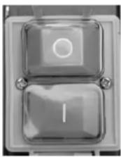
Switching off

Press the red button (O).
The built-in motor brake will decelerate the saw blade up to the dead stop within 10 seconds.

The saw must not be used if the brake is defective, i.e. if the time up to the saw blade's dead stop exceeds 10 seconds.
Motor guard
The motor is equipped with a guard switch and it switches off automatically when overload. The motor can be switched on again after a cooling-down period (approx. 5 – 10 minutes.).

Working with the saw

Before starting to work consider the following safety advices to keep the risk of injuries as small as possible.
- Saw blade, plastics inserts and recuperating spring o. k.?
■ Workplace tidied? - You may not start to operate the machine until you have read these operating instructions, observed all the instructions given and installed the machine as described!

Before making adjustments to the saw settings (e.g. replacing the saw blade etc.)
- switch off device
- wait for standstill of the saw blade.
– pull out power plug

Also, note the following important points:
- Place yourself outside of the area of danger.
- Place the wood piece in the jigging device. Cut through the piece with uniform pressure.
- Never remove loose splinters, chips, or similar by hand.

At any case pay attention to all safety instructions.
Working instructions
▶ Place the wood piece in the jigging device.
⚠️ Only wood pieces with a diameter between 30 mm and 140 mm are allowed to be sawed.
▶ 18 Use the support extension (6) for long wood pieces. Loosen the wing screw (15), pull out the extension a bit and fix it again.
▶ 21 You will get pieces of equal length if you pull out the length stop (14) and fix it in the desired position using the wing screw (15).
▶ Close the safety flap (4).
⚠ Saw only with the safety flap closed.
▶ Hold the handles (5 / 4a) with both hands and push the jigging device uniformly towards the saw blade. Avoid erratic movements.
The barbs on the jigging device prevent any turning of the wood piece during sawing.
Do not force the jigging device against the saw blade, the motor speed should not drop too far.
▶ After cutting, the jigging device is automatically brought back to its home position by spring force.
In the home position, all of the saw blade (incl. cutting teeth) is covered by the saw blade casing.
If the recuperating spring (16b) is broken or worn, the jigging device will not automatically return to its home position. Replace the recuperating spring. See “Replacing the return spring”.
Never saw without or with a damaged recuperating spring. Only advance the wood piece after a completed sawing operation.
Conduct in case of accident or failure
- Press the red button (O) on the ON/OFF switch.
- Wait until the saw blade has come to a stop.
- Disconnect the mains plug.
- Initiate first aid actions in the event of injuries.
Conduct in the case of blocked saw blade due to stuck wood pieces
- Press the red button (O) on the ON/OFF switch.
- Disconnect the mains plug.
- Remove the blockage.
⚠️ Wear protective gloves.
Do not remove the stuck wood piece with your hands but using a suited wood piece.
- Check the saw blade for any damages.

Maintenance and cleaning
Before each maintenance and cleaning work - Switch off device
- Wait until the saw blade comes to a stop.
– Pull out power plug
Maintenance and repair work other than those described in this chapter is only allowed to be carried out by service staff.
For maintaining and cleaning, removed security devices must unconditionally be mounted properly and proved again.
Use only original parts. Other parts can result in unexpected damages and injuries.
Cleaning
i Observe the following to maintain the operability of the machine:
- Do not wash down device with water.
■ Remove shavings and dust only with a brush or vacuum cleaner.
■ Clean and oil all moving parts regularly.
i Never use any grease!
Use for instance sewing machine oil, liquid hydraulic fluid or environmentally acceptable spray oil.
■ Take care that the saw blade remain free of rust and resin.
■ Remove resin residues from the push frame surface.
i Resin residues can be removed with a commercial maintenance and care spray.
- The saw blade is a wearing part and will become dull after prolonged or frequent use.
Renew the saw blade or have it sharpened
Maintenance
Changing the saw blade


Remove the mains plug before changing the saw blade.

Danger of cutting! The saw blade is massive and it could be to slick. Wear gloves when replacing the saw blade.
- Do not use any saw blades made of HSS steel.
- Do not use any cracked saw blades or such that have changed their shape.
■ Only use well-sharpened saw blades.

Danger of burning! The saw blade is still hot shortly after cutting.

Unscrew the limit blade (3).
Loosen the locking plate (13).

Remove the cotter pin (16c) and the washer (16d).
Remove one end of the safety chain (10).
When doing so, firmly hold the tilt table.

Slowly lower the tilt table (7) towards the ground.

Bolt down the outside saw blade cover (2).

Loosen the locking nut M20x1.5 with the open-end wrench (25) the ring spanner (26).
Now, the front saw blade flange (23) and the saw blade (22) can be removed.

Clean the saw blade flanges (23, 21).
Install a new or sharpened saw blade (22).

Pay attention to the correct running direction of the saw blade: The arrow on the saw blade and the arrow on the saw blade casing must point in the same direction!
Position the front saw blade flange again
The further assembly is now done in reverse sequence.

R-attach the locking plate (13).

Make sure after mounting that everything is tightened firmly.
Replacing the plastics insert

Immediately replace the worn or damaged plastics inserts (24).

Loosen the screws of the plastics insert and remove them.
Insert a new plastic insert and screw it tightly in place.
Replacing the recuperating spring

Immediately replace a worn or damaged recuperation spring

Loosen the locking plate (13).

Remove one end of the safety chain (10).
When doing so, firmly hold the tilt table.
Remove the cotter pin (16c) and the first washer (16d) and pull out the bolt (16a) from the bracket.

Slowly lower the tilt table (7) towards the ground
Remove the second washer and the recuperating spring (16b).
Slide a new recuperating spring and washer on the recuperating bolt (16a)
The further assembly is now done in reverse sequence.

Re-attach the locking plate (13).

Make sure after mounting that all screws are tightened firmly.
Transport


Remove mains plug before each transport.
Storage


Pull out power plug
- Store unused equipment in a dry, locked place out of the reach of children. - Before a longer period of storage carry out the following to extend the saw service life and ensure an easy operating:
→ thoroughly clean the device
→ treat all movable parts with an environmentally friendly oil

Never use any grease!
Guarantee
Please observe the enclosed terms of guarantee.
Possible faults
Before each fault elimination:
- Switch off device
- Wait until the saw comes to a stop
– Pull out power plug
After each fault clearance, put into operation and recheck all security installations.
| Fault Possible cause Remedy | ||
| Machine fails to start after switching on | Power failureExtension cable defectMotor or switch defect | Check the fuse.Check cable, no longer use defect cableHave motor or switch checked by an approved electrician or replaced by original spare parts |
| Jigging does not work | Safety flap not pressed down properly. | Press down the safety flap properly. |
| Machine stops while cutting | Saw blade bluntFeed is too great | Replace saw blade or have it sharpendAllow motor to cool and proceed working with less pressure |
| Burned spots at the cut areas | Saw blade blunt | Replace saw blade or have it sharpend |
| Saw vibrates | Saw blade is warpedSaw blade not properly mounted | Replace saw blade or have it sharpendMount saw blade properly |
| Recuperating mechanism of the jigging device does not work | Recuperating spring broken or worn outRecuperating bolt popped out from its bracket | Replace the recuperating springInsert the recuperating bolt in its bracket and secure it with a cotter pin |
| Deceleration too slow (time to dead stop >10 sec.) | Motor brake defective | Have motor or switch checked by an approved electrician or replaced by original spare parts |
Technical data
| Type BWS 400-2 | |
| Year of construction see last page | |
| Motor rating P1 2.2 KW (S2 15 Min – temporary duty 15 minutes) | |
| Mains voltage 230 V~ | |
| Mains frequency 50 Hz | |
| No-load speed n0 | 2800 min -1 |
| Protection class IP 54 | |
| Mains fuse | 16 A slow |
| Saw blade (carbide tipped saw blade) | ∅ 405 mm |
| Saw blade location hole ∅ | 30 mm |
| Number of teeth 32 | |
| Thickness of splitting wedge 2.2 mm | |
| Cut width 3.0 mm | |
| max. cutting capacity | approx. ∅ min. 30 mm to max. 140 mm |
| Wood length, max. 1000 mm | |
| Wood length, min. | 300 mm |
| Dimensions (length x breadth x height) | 1002 x 737 x 1046 mm |
| Weight (incl. accessories) | 38.3 kg |
Technical modifications reserved!

natural_image
Close-up of a transparent square button with two glossy surfaces and a circular mark on top (no text or symbols visible)Mise en arrêt

i Kontrollér alt for fast montering.
Kontrollér alt for fast montering.
Kontrollér alt for fast montering.
Transport


Før hver transport skal netstikket tages ud.
Opbevaring


Træk netstikket ud.
natural_image
Close-up of a metallic mechanical component with two square buttons and a circular button (no text or symbols visible)Uitschakelen

Druk de rode knop (O).
conform Directivei UE: 2006/42/UE
Prin prezenta noi
Altrad Lescha Atika GmbH
Josef-Drexler-Str. 8, 89331 Burgau - Germania
[2x scruv M8x40, 4x bricka ∅ 8, 2x mutter M8]
Montera vaggan (7) på stativet (8).
[2x scruv M8x70, 6x bricka ∅ 8, 2x mutter M8]
natural_image
Close-up of a metallic square button with two glossy surfaces and a circular symbol on top (no text or symbols visible)Fränkoppling

natural_image
Close-up of a metallic mechanical component with two glossy surfaces and a central circular feature (no text or symbols visible)Vypnutie pily

Year of construction