PCI 7DC RB - Speaker TANNOY - Free user manual and instructions
Find the device manual for free PCI 7DC RB TANNOY in PDF.

User questions about PCI 7DC RB TANNOY
0 question about this device. Answer the ones you know or ask your own.
Ask a new question about this device
Download the instructions for your Speaker in PDF format for free! Find your manual PCI 7DC RB - TANNOY and take your electronic device back in hand. On this page are published all the documents necessary for the use of your device. PCI 7DC RB by TANNOY.
USER MANUAL PCI 7DC RB TANNOY
natural_image
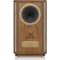
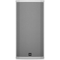
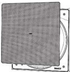
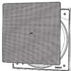
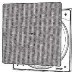
Close-up of a gray mesh panel with a small white mark in the center (no text or symbols)PCI 7DC RB
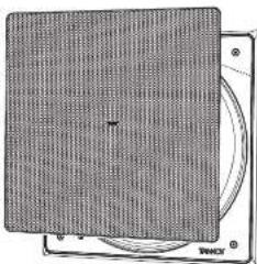
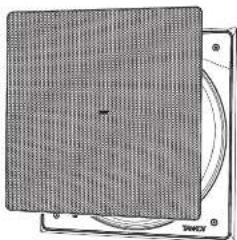
Premium 7" Dual Concentric In-Ceiling Loudspeaker for Installation Applications
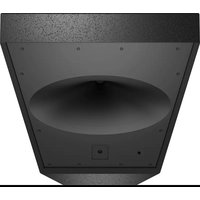
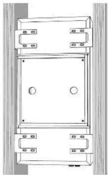
BACK CAN PCI 7DC RB
Back Can Kit for PCI 7DC RB In-Ceiling Loudspeakers
EN
ES
FR
DE
PT
IT
NL
SE
PL
-
Do not defeat the safety purpose of the polarized or grounding-type plug. A polarized plug has two blades with one wider than the other. A grounding-type plug has two blades and a third grounding proing. The wide blade or the third proing are provided for your safety. If the provided plug does not fit into your outlet, consult an electrician for replacement of the obsolete outlet.
-
Protect the power card from being walked on or pinched particularly at plugs, convenience receptacles, and the point where they exit from the apparatus.
-
Use only attachments/accessories specified by the manufacturer.

- Use only with the cart, stand, tripod, bracket, or table specified by the manufacturer, or sold with the apparatus. When a cart is used, use caution when moving the cart/apparatus combination to avoid
injury from tip-over.
-
Unplug this apparatus during lightning storms or when unused for long periods of time.
-
Refer all servicing to qualified service personnel. Servicing is required when the apparatus has been damaged in any way, such as power supply cord or plug in damaged, liquid has been spilled or objects have fallen into the apparatus, the apparatus has been exposed to rain or moisture, does not operate normally, or has been dropped.
-
The apparatus shall be connected to a MANG socket outlet with a protective earthing connection.
-
Where the MAINS plug or an appliance coupler is used as the disconnect device, the disconnect device shall remain nearly operable.

- Correct disposal of this product: This symbol indicates that this product must not be disposed at with household waste, according to the WEE Directive (2012/19/EU) and
should be taken to a collection center licensed for the recycling of waste electrical and electronic equipment. EEL, the misunderstanding of this type of waste could have a possible negative impact on the environment and human health due to potentially hazardous substances that are generally associated with EEL, at the same time your cooperation in the correct disposal of this product will contribute to the efficient use of natural resources. For more information about where you can take your waste equipment for recycling, please contact your local city office, or your households waste collection service. 18. Do not install in a confined space, such as a book case or similar unit.
-
Do not place naked flame sources, such as lighted candles, on the apparatus.
-
Please keep the environmental aspects of battery disposal in mind. Batteries must be disposed-of at a battery collection point.
-
This apparatus may be used in tropical and moderate climates up to 45°C.
LEGAL DISCLAIMER
Music Tribe accepts no liability for any loss which may be suffered by any person who relies either wholly or in part upon any description, photograph, or statement contained herein. Technical specifications, appearances and other information are subject to change without notice. All trademarks are the property of their respective owners. Vidas, Klark Teknik, Lab Suggers, Lake, Tanney, Turbosound, TC Electronic, TC Helicon, Behringes, Sugera, Osterheim, Auratone, Aston Microphones and Coledudio are trademarks or registered trademarks of Music in The Global Brands Ltd. © Music Tribe Global Brands Ltd. 2021 All rights reserved.
LIMITED WARRANTY
For the applicable warranty terms and conditions and additional information regarding Music Tribe's Limited Warranty, please see complete details online at musictribe.com/warranty.
BESCHRÄNKTE GARANTIE
Thank you for purchasing this Tamney premium Dual Concentric Loudspeaker for installation Applications. Tamney in coiling speaker systems are monitor quality speaker systems based on the company's expertise in the manufacture of premium quality cabinet loudspeakers and studio monitors. Exclusive drive unit designs and wide bandwidth technology ensure that these loudspeakers deliver the performance that is essential for applications such as multi-room distributed audio installations, home theatre systems and discrete audio systems, as well as in the many other applications where space is at a premium but ultimate sound quality is still paramount. The speaker construction is based around a rigid moulded ABSaffle with excellent structural integrity; this, when combined with the secure polyacetonate clamp mounting system [patient applied for .0316897.9], ensures a performance-enhancing rigid acoustic coupling with the wall surface, and an immensely stable platform for the drivers to deliver optimum performance. Complementing any style of decor, the perforated metal grille and low profile mounting frame can be painted to blend in seamlessly with the domestic environment. The result is a system offering audible quality sound with minimal invasion of the living space.
Unpacking
Every Tannoy product is carefully inspected before shipment. After unpacking, please inspect your product to ensure no damage has occurred in transit. In the unlikely event of damage, please notify your dealer and retain all shipping materials as your dealer may require return shipment.
Safety Notices
Tannoy will not be held responsible for any damages caused by the improper installation of these loudspeakers.
ES
Introducción
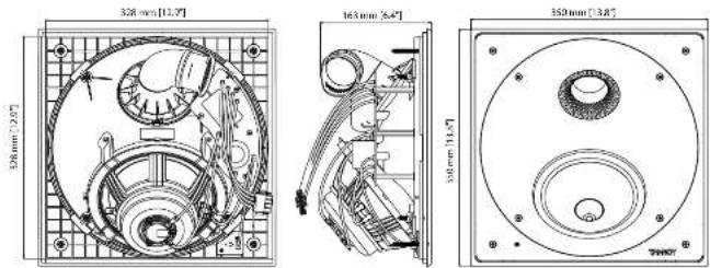
Product Feature Identification
PCI 7DC RB
Loudspeaker Assembly
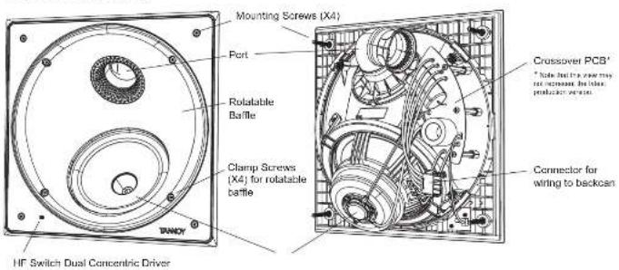
text_image
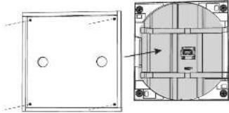
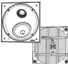
Mounting Screws (X4) Port Rotatable Baffle Clamp Screws (X4) for rotatable baffle Crossover PCB' * Note: This is a mode may not increase the baller producer's wire. Connector for wiring to backoan HF Switch Dual Concentric DriverGrille
natural_image
Close-up of a textured gray surface with a small black dot at center (no text or symbols)Back Can Assembly
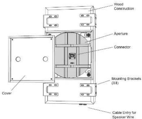
text_image
Wood Construction Aperture Connector Mounting Brackets (X4) Cable Entry for Speaker Wire CoverPaint Mask
natural_image
Simple line drawing of a rectangular frame with rounded corners (no text or symbols)PCI 7DC RB Installation Guide
PCI 7DC RB Back Can Installation
WARNING: This procedure requires the use of an assistant, and the use of personal protection equipment, such as safety glasses and gloves.
WARNING: To avoid potential damage to your loudspeaker, ensure that the power amplifier is switched OFF prior to connecting or disconnecting any cables.
WARNING: Make sure that there are no power lines, other cables, or plumbing such as water, sewer, gas lines in the chosen location.
The procedure below describes the installation of the back can into a typical
2" x 8" post ceiling with 16" centers, with drywall plaster board not yet installed.
After the back can and drywall is installed, the PCI 7DC RB loudspeaker can be wired and installed, and the paint mask added for painting and finishing.
Procedure
Follow the procedure steps below in the order in which they are presented. Read all the instructions before starting.
- Locate a suitable mounting position for the loudspeaker that will offer optimum acoustic performance for the listening environment and audio system, and that is also practical and aesthetically pleasing. The location should also allow enough room for the speaker wire to enter the back can at one end.
-
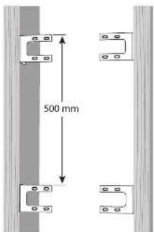
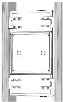
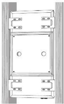
Position the brackets as shown in Fig. 1, making sure that the lower faces of the brackets are flush with the lower face of the ceiling joints. Secure each bracket to the ceiling joist using four screws per bracket.
-
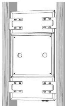
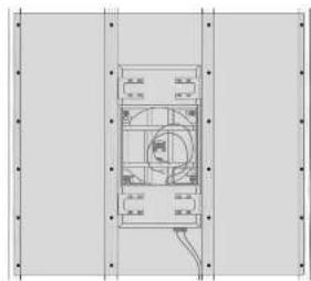
With the help of an assistant, carefully lift the back can to the chosen location between the ceiling joists, and lift and slide it into place, until it is supported by the four brackets and centered between them (Fig. 2).
-
Secure the back can to the brackets, using four screws per bracket.
text_image
500 mmFig. 1 Screw the back can brackets to the ceiling joists
natural_image
Technical line drawing of a mechanical assembly with mounting brackets and central components (no text or symbols)Fig. 2 Screw the brackets and back can together.
Quick Star Guide
Wiring
WARNING: To avoid potential damage to your loudspeaker, ensure that the
amplifier is switched OFF prior to connecting or disconnecting any cables.
WARNING: Before switching the amplifier ON, double check that all connections are secure and that the polarity is correct.
(Note that the speaker wire connections are made to the internal terminals inside the back can.)
The screw terminals are designed to take substantial high quality
loudspeaker cable.
-
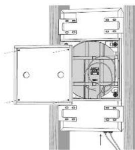
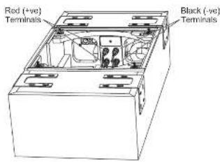
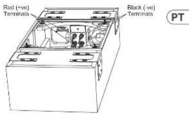
Remove the cover from the back can by undezing the four screws holding it in place (Fig. 3).
-
Install the speaker wire in through one of the cable glands, and leave enough slack to make the connections (Fig. 3). Tighten the cable gland, and tie down the speaker cable to prevent it moving and rettling in operation. Make sure that the speaker cable does not come into contact with nails or screws that might damage the insulation. A second cable gland is provided to allow a second speaker cable run to be installed.
- Pull out the speaker cables and strip off approximately 8 mm (N") of the outer protective layer from each conductor.
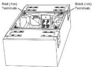
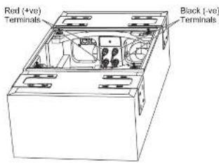
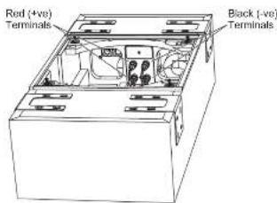
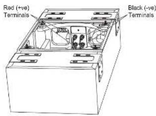
- The positive wire from your amplifier should go to one of the red (positive) terminals inside the back can (Fig.4). The negative wire from your amplifier should connect to one of the black (negative) terminals. You can use the other red and black terminals to run speaker wiring out of the other cable gland and out to another speaker.
- Make sure that the speaker cables are secured so they will not move and touch the speaker cone when it is installed.
natural_image
Technical line drawing of a mechanical assembly with no visible text or symbolsFig. 3. Speaker Wire Installation.

text_image
Red (+ve) Terminals Black (-ve) TerminalsFig. 4. Cover removed from back can, showing the speaker terminals
Installing the Drywall
-
The installation of drywall around the back can location is best done using a single large sheet centered around the back can location (Fig. 4). Use adhesive on the front face of the back can, and on the ceiling joists, and install the drywall using drywall screws approximately 8 to 10 inches apart. This will help prevent ceiling rattling and drywall movement and moves during operation. COUTION: Make sure that no drywall screws go into the wooden case of the back can at any point.
-
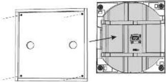
After drywall installation, carefully cut out the hole in the drywall with a suitable handtool, using the rectangular aperture of the back can as a guide (Fig. 5). Be careful not to cut the speaker wires or any of the back can wood. Assume the drywall aperture is no larger than the aperture of the back can. Remove any dust or debris from within the back can.
-
Install the back can cover using the four screws. This cover can be left in place during painting and finishing of the ceiling, and then removed when the loudspeaker assembly is ready for installation. (Painting can also be done when the loudspeaker assembly is position, as it is supplied with a painting mask.)
natural_image
Technical line drawing of a mechanical component with mounting flanges and internal circular features (no text or symbols)Fig. 4. Drywall Screws.
natural_image
Technical diagram showing front and side views of a mechanical or electrical component with circular features (no text or symbols)Fig. S. Drywall Removed from the Aperture, and Cover Installed
Installation into the Back Can
With the back can installed and wired as shown in the previous pages, the loudspeaker assembly can now be installed into the ceiling and back can.
- Remove the back can cover if it is in place.
- With the help of an assistant, hold the speaker assembly up close to the back can aperture.
- The loudspeaker has four wires and a connector attached. Securely join this to the matching connector in the center of the back can aperture.
- The speaker assembly can now be connected to the back can using four screws as shown. Take care not to trap or pinch the speaker wiring, or your fingers or tie (Fig. 6).
Painting
- A paint mask is supplied to protect the loudspeaker from paint, dust, and debris. It allows you to paint and finish the ceiling after the installation of the loudspeaker into the ceiling.
- Press the paint mask into the loudspeaker assembly, and it will be kept in place by magnets. This is left in place while the ceiling and frame surround is painted
- It is strongly recommended that the metal perforated grille is sprayed, as this will avoid clogging of the holes. If painting with a brush is the only option, then several thin coats of paint will provide a superior finish to that achieved by one applied too thicky.
natural_image
Technical line drawing of a mechanical component with circular and rectangular features (no text or symbols)Fig. 6. Connecting the speaker wiring to the back can
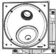
Fig. 7, Installing the loudspeaker assembly into the back can
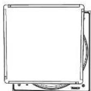
Fig. B. Installing the paint mask over the loudspeaker assembly
Baffle Rotation
- The loudspeaker baffle assembly can be rotated to alter the coverage to suit your installation. This is the equivalent of 'toeing in' free-standing speakers to face your normal listening position.
- Undo the four screws as shown, but just enough to allow the rotation to the desired position (Fig. 9).
- Gently tighten the four screws when done, just enough to prevent movement during use. The baffle can be rotated through 17-45 degrees.
- Test the system and readjust the position if needed.
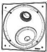
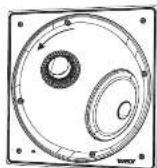
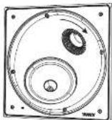
Fig. 9. Rotating the baffle assembly
HF Switch Adjustment
- The HF switch has three positions, with 0 dB being flat. Adjust as necessary to suit the more positive and acoustic conditions (Fig. 10).
- Test the system and reset the switch position if needed.
Grille Installation
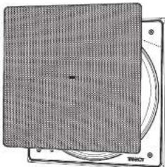
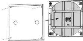
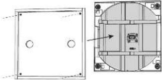
- The grille should be carefully fitted by lining up the edges of the grille carefully with the baffle and frame inside edges (Fig. 11). To avoid indentation damage, do not press the centre of the grille: apply even pressure to each corner as it is pressed firmly into position.
- To remove the grille, loop an opened paper clip or similar length of firm wire, through two holes near a corner and pull gently. The grille is intended to be a tight fit, so insert the wire at each corner in turn, pulling carefully to avoid distortion of the mesh.
System Testing
- Switch on the amplifier with the volume control at its lowest setting. Select a suitable signal source and slowly turn up the volume to a low level. Check that the loudspeaker is working correctly and is in phase - if not, switch off the amplifier and recheck the connections.
- Carefully check the area surrounding the installation and listen carefully to ensure that there are no buzzes or rattles that could potentially impair enjoyment of the system. If there are, then locate and silence the causes using cable ties or suitable packing material.
text_image
10mm -12.88 25mmFig. 10. HF Switch Positions
natural_image
Diagram of a CD or DVD disc with mesh pattern and circular frame (no text or symbols)Fig. 11, installing the Grille
PCI 7DC RB Installation Guide
Fig. 1 Screw the back can brackets to the ceiling joists
natural_image
Technical line drawing of a mechanical enclosure or enclosure with mounting brackets and circular features (no text or symbols)Fig. 2 Screw the brackets and back can together.
Alambrado
natural_image
Architectural floor plan showing room layouts and structural elements (no text or labels)Fig. 3. Speaker Wire Installation.

text_image
Red (+ve) Terminals Black (-ve) TerminalsFig. 4. Cover removed from back can, showing the speaker terminals
Quick Star Guide
natural_image
Technical diagram showing front and side views of a mechanical component with circular features (no text or symbols)Fig. 5. Drywall Removed from the Aperture, and Cover Installed
natural_image
Technical line drawing of a mechanical component with circular and rectangular features (no text or symbols)Fig. 6. Connecting the speaker wiring to the back can

Fig. 7. Installing the loudspeaker assembly into the back can
Fig. 8. Installing the paint mask over the loudspeaker assembly
Quick Star Guide
text_image
Technical diagram of a mechanical component with labeled parts and annotations in ChineseFig. 10. HF Switch Positions
natural_image
Diagram of a CD or DVD disc with a mesh pattern on top, showing front and back views (no text or symbols)Fig. 11. Installing the Grille
Fig. 1 Screw the back can brackets to the ceiling joists
natural_image
Technical line drawing of a mechanical assembly with mounting brackets and central circular features (no text or symbols)Fig. 2 Screw the brackets and back can together.
Quick Star Guide
Câblage
natural_image
Architectural cross-section diagram of a room with doors, ceiling lights, and internal equipment (no text or labels)Fig. 3. Speaker Wire Installation.
text_image
Red (+ve) Terminals Black (-ve) TerminalsFig. 4. Cover removed from back can, showing the speaker terminals
Installation de la cloison sèche
natural_image
Architectural floor plan showing room layout and ceiling structure (no text or labels)Fig. 4. Drywall Screws.

natural_image
Technical drawing showing front and side views of a mechanical component (no text or symbols)Fig. S. Drywall Removed from the Aperture, and Cover Installed
natural_image
Technical line drawing of a mechanical component with top and side views (no text or symbols)Fig. 6. Connecting the speaker wiring to the back can
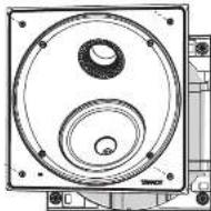
Fig. 7. Installing the loudspeaker assembly into the back can

Fig. B. Installing the paint mask over the loudspeaker assembly
Quick Star Guide
natural_image
Diagram of a CD or DVD disc with visible internal structure and mounting base (no text or symbols)Fig. 11, installing the Grille
PCI 7DC RB Installationshandbuch
PCI 7DC RB Back Can Installation
Fig. 1 Screw the back can brackets to the ceiling joists
natural_image
Technical line drawing of a mechanical enclosure or enclosure with mounting holes and a central square (no text or symbols)Fig. 2 Screw the brackets and back can together.
Verdrahtung
natural_image
Technical line drawing of an open electrical cabinet or enclosure with internal components and wiring (no text or symbols)Fig. 3. Speaker Wire Installation.
text_image
Red (+ve) Terminals Black (-ve) TerminalsFig. 4. Cover removed from back can, showing the speaker terminals
Quick Star Guide
Trockenbau installieren
text_image
Technical diagram showing a mechanical or electrical component with labeled parts and dimensionsFig. 4. Drywall Screws.
natural_image
Technical diagram showing a front view and side view of a mechanical component with mounting holes (no text or symbols)Fig. 5. Drywall Removed from the Aperture, and Cover Installed
natural_image
Technical line drawing of a mechanical component with circular and rectangular features (no text or symbols)Fig. 6. Connecting the speaker wiring to the back can

Fig. 7. Installing the loudspeaker assembly into the back can
Fig. 8. Installing the paint mask over the loudspeaker assembly
Quick Star Guide
Schallwanddrehung
text_image
H-10 H-20 H-30 W/WRFig. 10. HF Switch Positions
natural_image
Diagram of a CD-ROM drive showing front panel and rear cover (no text or symbols)Fig. 11. Installing the Grille
Fig. 1 Screw the back can brackets to the ceiling joists
natural_image
Technical line drawing of a mechanical assembly with mounting brackets and circular features (no text or symbols)Fig. 2 Screw the brackets and back can together.
Quick Star Guide
Fiação
natural_image
Technical line drawing of an electrical cabinet or enclosure with internal components and wiring (no text or symbols)Fig. 3. Speaker Wire Installation.
text_image
Red (+ve) Terminals Black (-ve) Terminals PTFig. 4. Cover removed from back can, showing the speaker terminals
Instalando o Drywall
natural_image
Architectural floor plan showing room layouts and structural elements (no text or labels)Fig. 4. Drywall Screws.
natural_image
Technical drawing showing front and top views of a mechanical component with circular features (no text or symbols)Fig. S. Drywall Removed from the Aperture, and Cover Installed
natural_image
Technical line drawing of a mechanical component with circular features and mounting holes (no text or symbols)Fig. 6. Connecting the speaker wiring to the back can
Fig. 7, Installing the loudspeaker assembly into the back can

Fig. B. Installing the paint mask over the loudspeaker assembly
Rotação do defletor
natural_image
Technical line drawing of a circular mechanical component with concentric rings and mounting holes (no text or symbols)Fig. 10. HF Switch Positions
natural_image
Diagram of a CD or DVD disc with visible internal structure and external frame (no text or symbols)Fig. 11, installing the Grille
Fig. 1 Screw the back can brackets to the ceiling joists
natural_image
Technical line drawing of a mechanical enclosure or enclosure with mounting brackets and central circular features (no text or symbols)Fig. 2 Screw the brackets and back can together.
Cablaggio
natural_image
Technical line drawing of an electrical enclosure or enclosure with internal components and wiring (no text or symbols)Fig. 3. Speaker Wire Installation.
text_image
Red (+ve) Terminals Black (-ve) TerminalsFig. 4. Cover removed from back can, showing the speaker terminals
Quick Star Guide
45
natural_image
Technical line drawing of a mechanical or electrical component with mounting flanges and internal components (no text or symbols)Fig. 4. Drywall Screws.
natural_image
Technical diagram showing front and side views of a mechanical or electrical component with circular holes and internal structural elements (no text or symbols)Fig. 5. Drywall Removed from the Aperture, and Cover Installed
natural_image
Technical line drawing of a mechanical component with circular and rectangular features (no text or symbols)Fig. 6. Connecting the speaker wiring to the back can
Fig. 7. Installing the loudspeaker assembly into the back can

Fig. 8. Installing the paint mask over the loudspeaker assembly
Pittura
text_image
Technical diagram of a mechanical component with labeled parts and a magnified inset showing internal features.Fig. 10. HF Switch Positions
natural_image
Diagram of a CD or DVD disc with a mesh pattern on top and a circular base, no text or symbols present.Fig. 11. Installing the Grille
Fig. 1 Screw the back can brackets to the ceiling joists
natural_image
Technical line drawing of a mechanical or electrical component with mounting holes and a central square (no text or symbols)Fig. 2 Screw the brackets and back can together.
Bedrading
natural_image
Architectural floor plan showing room layouts and equipment layout (no text or labels)Fig. 3. Speaker Wire Installation.

text_image
Red (+ve) Terminals Black (-ve) TerminalsFig. 4. Cover removed from back can, showing the speaker terminals
natural_image
Architectural floor plan showing room layouts and structural elements (no text or labels)Fig. 4. Drywall Screws.

natural_image
Technical drawing showing front and top views of a mechanical component with circular features (no text or symbols)Fig. S. Drywall Removed from the Aperture, and Cover Installed
Installatie in de Back Can
natural_image
Technical drawing of a mechanical component with front and side views (no text or symbols)Fig. 6. Connecting the speaker wiring to the back can

Fig. 7, Installing the loudspeaker assembly into the back can
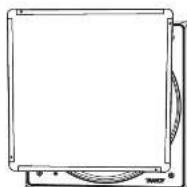
Fig. B. Installing the paint mask over the loudspeaker assembly
Baffle-rotatie
text_image
10mm -12.88 25mmFig. 10. HF Switch Positions
natural_image
Illustration of a CD or DVD disc mounted on a stand, showing textured surface and circular frame (no text or symbols)Fig. 11, installing the Grille
Fig. 1 Screw the back can brackets to the ceiling joists

natural_image
Technical line drawing of a mechanical or electrical enclosure with mounting brackets and circular features (no text or symbols)Fig. 2 Screw the brackets and back can together.
Kabeldragning
natural_image
Technical line drawing of an electrical cabinet or enclosure with internal components and wiring (no text or symbols)Fig. 3. Speaker Wire Installation.
text_image
Red (+ve) Terminals Black (-ve) TerminalsFig. 4. Cover removed from back can, showing the speaker terminals
Quick Star Guide
55
Installera gips
natural_image
Technical line drawing of a mechanical component with mounting holes and internal circular features (no text or symbols)Fig. 4. Drywall Screws.

natural_image
Technical diagram showing a front view and internal layout of a mechanical or architectural component (no text or symbols present)Fig. 5. Drywall Removed from the Aperture, and Cover Installed
Installation i bakkanten
natural_image
Technical drawing of a mechanical component with circular and rectangular features (no text or symbols)Fig. 6. Connecting the speaker wiring to the back can

Fig. 7. Installing the loudspeaker assembly into the back can
Fig. 8. Installing the paint mask over the loudspeaker assembly
Quick Star Guide
Baffelrotation
text_image
H-10 H-20 H-30 W/WRFig. 10. HF Switch Positions

natural_image
Diagram of a CD or DVD disc with visible internal structure and base plate (no text or symbols)Fig. 11. Installing the Grille
Fig. 1 Screw the back can brackets to the ceiling joists

natural_image
Technical line drawing of a mechanical or electrical component with mounting holes and a central square (no text or symbols)Fig. 2 Screw the brackets and back can together.
Okablowanie
natural_image
Architectural floor plan showing room layouts and equipment layout (no text or labels)Fig. 3. Speaker Wire Installation.
text_image
Red (+ve) Terminals Black (-ve) TerminalsFig. 4. Cover removed from back can, showing the speaker terminals
natural_image
Architectural floor plan showing room layouts and structural elements (no text or labels)Fig. 4. Drywall Screws.

natural_image
Technical drawing showing front and top views of a mechanical component with circular features (no text or symbols)Fig. S. Drywall Removed from the Aperture, and Cover Installed
natural_image
Technical line drawing of a mechanical component with circular features and mounting holes (no text or symbols)Fig. 6. Connecting the speaker wiring to the back can

Fig. 7, Installing the loudspeaker assembly into the back can
Fig. B. Installing the paint mask over the loudspeaker assembly
Obrót przegrody
natural_image
Technical line drawing of a circular mechanical component with concentric rings and mounting holes (no text or symbols)Fig. 10. HF Switch Positions
natural_image
Diagram of a CD or DVD disc with visible bands and frame structure (no text or symbols)Fig. 11, installing the Grille
Dimensions
PCI 7DC RB
PCI 7DC RB Back Can
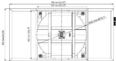
text_image
700 mm [22,6"] 333 mm [13,1"] 355 mm [15,7"] 333 mm [15,7"] 2033 mm [27,1]"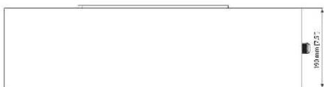
text_image
100mm x 3.72EN
Specifications
PCI 7DCRB
| Performance | |
| Frequency response (1.3 dB) 60 Hz – 25 kHz | |
| Frequency response (10 dB) 40 Hz – 20 kHz | |
| Sensitivity (10 W ± 1 m) 91 dB | |
| Directivity factor (Q) 5.7 averaged 1 kHz to 10 kHz | |
| Directivity index (IUI) 7.6 averaged 1 kHz to 10 kHz | |
| Power handling (CIC) | |
| Average 80 W | |
| Programme 160 W | |
| Peak 320 W | |
| Recommended amplifier power 240 V @ 8Ω | |
| Nominal impedance (Lo Z) 8Ω | |
| Rated maximum SPL (1 m, Lo Z) | |
| Average 110 dB | |
| Peak | 116 dB |
| Transformer tape | NA |
| Crossover point | 1.6 MHz |
| Coverage angles | |
| 520 Hz | 173° horizontal, 136° vertical |
| 1 MHz | 185° horizontal, 153° vertical |
| 2 MHz | 132° horizontal, 109° vertical |
| 4 MHz | 85° horizontal, 95° vertical |
| Transducers | |
| Low frequency diameter/material/type | 201 mm (7") |
| High frequency diameter/material/type | 25.4 mm (7") |
| Physical | |
| Enclosure | |
| Back-on | Wood, with spray painting |
| Brille | Reflex loaded 10.94 V @ most ABS |
| Grille | Steel, with weather/residential cooling |
| Safety features | N/A |
| Camping design | N/A |
| Connectors | Replacement Plug Increasing |
| Dimensions (inches) | 350 x 350 x 160 mm (13.8 x 13.8 x 6.3") |
| Borel dimensions | 5x20 350 mm (13.4"x13.8") |
| Mounting depth | 152 mm (6.0") |
| Hole cutout dimensions | 332 x 332 mm (13.1"x13.1") |
| Net weight | 3.8 kg 18.4 lbs |
| Packed quantity | 1 |
| Included accessories | Grille, paint mask, tool kit, winders (×2) screens (×2), paint washer (×2) |
| Back-on dimensions (H x W x O) | 35 x 290 x 190 mm (13.9 x 13.1 x 7.5") |
Other important information

Important information

Informations importantes

Other important information

Hemby, Music Tribe declares that this product is in compliance with Directive 2011/65/EU and Amendment 2015/863/EU, Directive 2012/19/EU, Regulation 519/2012 REACH SVHC and Directive 1907/2006/EC, and this passive product is not applicable to EMC Directive 2014/30/EU. LV Directive 2014/35/EU.
Full text of EU DoC is available at https://community.musicnibe.com/
EU Representative: Music Tribe Brands DK A/S Address: Ib Spang Olsens Gate 17, DK - B200 Aarhus N, Denmark