Platinum VoiceMaster Pro - Audio Equipment FOCUSRITE - Free user manual and instructions
Find the device manual for free Platinum VoiceMaster Pro FOCUSRITE in PDF.


User questions about Platinum VoiceMaster Pro FOCUSRITE
0 question about this device. Answer the ones you know or ask your own.
Ask a new question about this device
Download the instructions for your Audio Equipment in PDF format for free! Find your manual Platinum VoiceMaster Pro - FOCUSRITE and take your electronic device back in hand. On this page are published all the documents necessary for the use of your device. Platinum VoiceMaster Pro by FOCUSRITE.
USER MANUAL Platinum VoiceMaster Pro FOCUSRITE
text_image
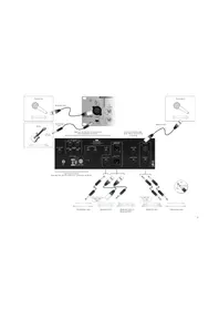
Microphone Balanced XLR Focusrite® Unbalanced Jack Guitar Guitar to best sound T1o T2o T3o Balance XLR Leistung-Free Monitoring connections (see 'Facilities & Controls') Insert connections [see 'Reer Panel Connections'] Balanced XLR Digital Output Option (seat separate documentation for connection guidance) Unbalanced Jack Balanced XLR Balanced Jack to Balanced XLR From syllable to best sound Balanced Jack Unbalanced JackCONTENTS
CONTENTS 2
IMPORTANT SAFETY INSTRUCTIONS....2
INTRODUCTION....3
GETTING TO KNOW THE UNIT 3
REAR PANEL CONNECTIONS....3
GETTING STARTED 4
FACILITIES AND CONTROLS....5
DISCRETE CLASS A PRE-AMP 5
OPTICAL EXPANDER....6
VINTAGE HARMONICS....6
OPTICAL COMPRESSOR....7
TUBE SOUND 8
VOICE OPTIMISED EQ....9
DE-ESSER....9
OUTPUT SECTION 10
LATENCY-FREE MONITORING....10
DIGITAL OUTPUT OPTION....11
OBTAINING GOOD QUALITY SOUND 12
CORRECTING PROBLEMS 12
A BEGINNER'S GUIDE TO COMPRESSION....13
A BEGINNER'S GUIDE TO EQUALISATION....15
FREQUENTLY ASKED QUESTIONS....15
TROUBLESHOOTING....17
CONTACTING US 17
SPECIFICATIONS 82
FOCUSRITE DISTRIBUTOR LIST....86
IMPORTANT SAFETY INSTRUCTIONS
Please read all of these instructions and save them for future reference. Follow all warnings and instructions marked on the unit.
- Do not obstruct air vents in the rear panel. Do not insert objects through any apertures.
- Do not use a damaged or frayed power cord.
- Unplug the unit before cleaning. Clean with a damp cloth only. Do not spill liquid on the unit.
- Ensure adequate airflow around the unit to prevent overheating. As this is a Class A unit, we recommend leaving a blank 1U panel above the unit to aid ventilation.
- Unplug the unit and refer servicing to qualified service personnel under the following conditions: If the power cord or plug is damaged; if liquid has entered the unit; if the unit has been dropped or the case damaged; if the unit does not operate normally or exhibits a distinct change in performance. Adjust only those controls that are covered by the operating instructions.
- Do not defeat the safety purpose of the polarised or grounding-type plug. A polarised plug has two blades with one wider than the other. A grounding type plug has two blades and a third grounding prong. The wider blade or the third prong is provided for your safety. When the plug provided does not fit into your outlet, consult an electrician for replacement of the obsolete outlet.
WARNING: THIS UNIT MUST BE EARTHED BY THE POWER CORD. UNDER NO CIRCUMSTANCES SHOULD THE MAINS EARTH BE DISCONNECTED FROM THE MAINS LEAD.
This unit is supplied pre-configured to operate only at the voltage indicated on the rear panel. Ensure correct mains voltage is available and the correct fuse value is fitted before connecting to the mains supply. To avoid the risk of fire, replace the mains fuse only with the correct value fuse, as marked on the rear panel. The internal power supply unit contains no user serviceable parts. Refer all servicing to a qualified service engineer, through the appropriate Focusrite dealer.
RACK VENTILATION: AS THE VOICEMASTER PRO IS A CLASS A DEVICE, PLEASE ENSURE IT IS PLACED TOWARDS THE BOTTOM OF YOUR EQUIPMENT RACK, WITH SUFFICIENT SPACE ABOVE AND BELOW FOR VENTILATION.
ENGLISH

text_image
SECURFE CLASS A RE-AMP OPTICAL EXPANSER VOLTAGE HANIMONICS OPTICAL COMPRESSOR RARE SOUND VOOL OPTIFIED IQ DELETS OUTPUT LEVELS FIRE LIME OUTPUT INDEX PROCES POWER VEGETABLE MONITORING FAIR LIME HEAVYMPONE HEAVYMPONE VOICE POKES VOLUME RANGE RANGE RANGE RANGE RANGE RANGE RANGE RANGE RANGE RANGE RANGE RANGE RANGE RANGE RANGE RANGE RANGE RANGE RANGE RANGE RANGE RANGE RANGE RANGE RANGE RANGE RANGE RANGE RANGE RANGE RANGE RANGE RANGE RANGEINTRODUCTION
The VoiceMaster Pro is a combined, high-performance microphone pre-amplifier, dynamics processor and equaliser. Although it has been specifically designed to enable the user to set up a great vocal sound, the VoiceMaster Pro is flexible enough to also be used when recording and mixing down a range of other instruments, such as guitars or drums.
When recording, do not assume you must route your signal through a mixing desk: simply connect a microphone to the VoiceMaster Pro and connect the output of the VoiceMaster Pro directly into your sound card or recording device. This form of direct recording will ensure you record the cleanest signal at the highest quality, since it removes the possibility of noise being added to the signal when routing through a mixer.
There are seven separate signal-processing sections in the VoiceMaster Pro:
• Discrete Class A Pre-amp
• Optical Expander
• Vintage Harmonics
• Optical Compressor
- Tube Sound
• Voice Optimised EQ
• Dc-Esscr
To ensure the cleanest signal path to your recording medium, each section can be individually switched out of the audio path ('hard bypassed') when not in use. There is also a global PROCESS BYPASS control.
GETTING TO KNOW THE UNIT
When you are getting to know the unit, use it with a sound source with which you are familiar. For example, you could run a favourite CD through the unit, as working with a familiar track makes interpretation of the results easier. (Note, however, that tracks are already compressed for CD, so you may find it hard to hear the results of using the Optical Compressor.) If this is the case, try using samples instead, or record your own track uncompressed and then play it back through the VoiceMaster Pro.
The easiest way to understand the creative power of the VoiceMaster Pro, particularly if you are not familiar with each of its separate parts, is to switch in each individual section, and try each control in turn. Finally try them all together to hear the creative power of the VoiceMaster Pro!
REAR PANEL CONNECTIONS
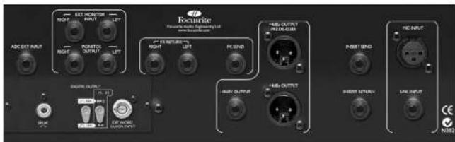
The VoiceMaster Pro features MIC INPUT XLR and LINE INPUT TRS connectors on the rear panel, with the MIC INPUT duplicated on the front fascia together with a
ENGLISH
quarter inch jack INSTRUMENT INPUT. The INSERT SEND and INSERT RETURN quarter inch jack connectors on the rear panel allow an additional processor to be inserted into the signal chain between the pre-amp and the other processing sections of the unit.
Outputs are provided on both XLR (balanced, +4 dBu) and quarter inch jack (unbalanced, -10 dBV), and there is also a PRE DE-ESSER output XLR (balanced, +4 dBu).
Additionally, the VoiceMaster Pro includes a mono, unbalanced FX SEND and balanced stereo FX RETURN with quarter inch jack connectors, to allow an effects unit to be monitored, together with balanced stereo EXT MONITOR INPUT and MONITOR OUTPUT connections on quarter inch 'TRS' jacks. See the LATENCY-FREE MONITORING and the EXT MONITOR INPUT/MONITOR OUTPUT sections on pages 10-11 for further details.
Finally, the ADC EXT INPUT (balanced, quarter inch TRS jack) allows an external signal to be routed to the second channel of the optional digital converter card. This allows the digital converter to be used for stereo mastering applications, as a standalone A/D converter, or simply to provide a second (line level) record input. For information on the optional digital output board, see page 11.
GETTING STARTED
- Ensure that nothing other than the mains supply is connected to your VoiceMaster Pro, then switch it on via the POWER switch on the right hand side of the unit. If your unit is permanently connected to a patchbay, ensure audio is not being fed to any connected speakers to avoid any turn-on speaker pops.
- Connect the appropriate OUTPUT (either +4 dBu balanced XLR or -10 dBV unbalanced jack) on the rear panel of the VoiceMaster Pro to your recorder or audio interface. If using the digital output option, connect the digital output to the digital input of your recorder or audio interface. See page 11 for more information on the VoiceMaster Pro digital output option.
- Connect the MONITOR inputs and outputs to your external kit/monitor speakers.
- Ensure that each processing section is switched out (IN switch disengaged and unlit), and that the PROCESS BYPASS switch is also disengaged (out).
- Connect your input source as required. A microphone can be plugged into the XLR MIC INPUT on either the front fascia or the rear panel. If you wish to connect a line-level source (to use the VoiceMaster Pro's dynamics processing when mixing
down, for example) connect this to the TRS LINE INPUT on the rear panel. Alternatively, you may connect an electric guitar or bass to the INSTRUMENT INPUT via the unbalanced quarter inch jack input on the front fascia.
-
Check that the correct input is selected in the DISCRETE CLASS A PRE-AMP section. If recording a line level source connected to the rear panel LINE INPUT, ensure the LINE switch is engaged. If a microphone is connected to either of the MIC INPUTS, or an electric guitar or bass is connected to the INSTRUMENT INPUT, ensure the LINE switch is disengaged.
-
Make sure the phase reverse (O) and HPF ( ) switches are disengaged and that the INPUT GAIN control is fully counter-clockwise. Set the OUTPUT FADER to the '0' position.
-
If using a condenser microphone that requires phantom power, engage the +48V switch. If you are unsure whether your microphone requires this phantom power, refer to its user guide. Phantom power can damage some microphones, especially ribbon microphones.
-
Increase the INPUT GAIN control, checking the input level meter LEDs and ensuring the red O/L LED does not illuminate, except occasionally and briefly when the loudest signal is present.
-
If using a microphone, ensure that the microphone placement is at its best. Before you start recording, alter the microphone placement until you get as close as possible to the sound you want. Note that moving the microphone may have an effect on the level of the signal entering the VoiceMaster Pro, requiring an alteration to the INPUT GAIN setting.
-
Add additional processing as required using the various signal-processing blocks, which may be individually switched in or out. For more information on the specific functions of the various sections, refer to the following section, FACILITIES AND CONTROLS.
FACILITIES AND CONTROLS
POWER (switch) - Turns the unit on. We recommend that the unit be powered up before connecting to any equipment that it is feeding, to avoid clicks or thumps which may harm output devices. It is also a good idea to allow the unit to stabilise for a couple of minutes before use to ensure that the internal circuitry is properly initialised.
DISCRETE CLASS A PRE-AMP
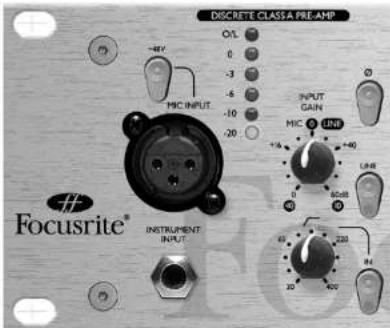
This part of the unit is a pre-amplifier, used to amplify the incoming signal being fed to the MIC INPUT or INSTRUMENT INPUT to a suitable level before any further processing is applied.
text_image
DISCRETE CLASSA PRE-AMP O/L 0 -3 -5 -10 -20 MIC INPUT INPUT GAIN MIC 4 INR +1/6 -40 -10 20 220 20 400 Focusrite® INSTRUMENT INPUTMIC INPUT - This is an XLR connector that allows you to connect a microphone to the unit. There is also a MIC INPUT XLR on the rear panel, but only one may be used at a time; do not connect both MIC INPUTs simultaneously. If using the VoiceMaster Pro's mic pre and feeding the output into a mixing console, bypass the console's own mic pre and connect to the channel's line input. This will mean the superior VoiceMaster Pro mic pre is used to route signal to its destination, e.g. a recording device, avoiding unwanted distortion and colouration from an inferior mic pre. Always avoid routing the VoiceMaster Pro's mic pre into a second mic pre, as this will produce greatly inferior results.
ENGLISH
+48V (switch) - This provides +48V of phantom power for condenser microphones (affecting the MIC INPUT only.) If you are unsure whether your microphone requires phantom power, refer to its user guide before connecting, as it is possible to damage some microphones (most notably ribbon microphones) by providing them with phantom power.
INSTRUMENT INPUT - This is a high impedance 1/4" jack input that allows you to connect an electric guitar or bass guitar to the unit without loading the pickups, and without the need for a DI box. If both the mic and instrument inputs are connected, the instrument input will override the mic input.
☐ (Phase Reverse switch) - This allows the phase of the input signal to be reversed e.g. to correct phase problems when incorrect wiring polarity has occurred.
LINE (switch) - When engaged (in), this switch selects the rear panel LINE INPUT, and an LED is illuminated in the switch cap to indicate that the LINE INPUT is active. If this is disengaged (out), the MIC INPUT and INSTRUMENT INPUT' are active.
(HPF knob and switch) - This is a high-pass filter, which removes unwanted low frequencies such as stage rumble via microphone stands, or 'proximity effect' (where low frequencies are over-emphasised when using certain types of microphone at close range). The knob sets the cut-off frequency (from 30 to 400 Hz, 18 dB per octave), and the switch must be engaged (in) for the control to function.
INPUT GAIN (knob) - This is used to set the optimum input signal level. Connect an input signal to the unit, ensuring that the INPUT GAIN control is set fully counter-clockwise, and increase the INPUT GAIN control whilst observing the LED signal meter. The red O/L (overload) LED may light occasionally, but only if the input signal gets particularly loud. If the O/L LED stays on continuously for any period, or you hear the unit distort during loud peaks, you should reduce the INPUT GAIN.
Note that the meter is calibrated to read 0 dBfs at the top of the meter- this has been set up to enable simple metering when recording to digital media. The best level to set for recording depends on your recording medium. If recording to an analogue medium like tape, where extra headroom is required, a level of -18 dBfs will give a suitable +4 dBu equivalent output. If recording to digital media, you may wish to record at a higher level, peaking at e.g. -4 to -6 dBfs. Confused? Visit www.sospubs.co.uk/sos/may00/articles/digital.htm for further illumination.
With the MIC INPUT selected, the INPUT GAIN control provides 0 dB (fully counter-clockwise) to +60 dB (fully clockwise) of gain. With the INSTRUMENT INPUT' selected, the INPUT' GAIN control provides +4 dB to +34 dB of gain. With
ENGLISH
the LINE INPUT selected, the gain is adjustable from -10 dB to +10 dB. Setting the LEVEL control to the 12 o'clock position will not alter the gain of a line level input signal.
INSERT (rear panel connections) - The INSERT connectors on the rear panel allow an additional external signal processor to be inserted into the signal chain between the pre-amp and the other processing sections of the VoiceMaster Pro. Connect the INSERT SEND to the line input of the external processor, and connect the processor's line output to the INSERT RETURN. Like all inserts, the signal returned to the INSERT RETURN jack will rejoin the signal path at the same point from which it was sent, after the benefit of external processing.
OPTICAL EXPANDER
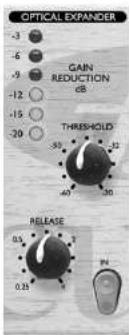
The OPTICAL EXPANDER reduces the volume of quiet sections in the performance, by reducing the gain of the signal when it falls below the threshold set by the user. 'This is a similar principle to a noise gate, but rather than muting the signal altogether, an expander simply 'turns the volume down'. Use it to get rid of background noise, either while recording, (for example, getting rid of bleed from headphones into the microphone,) or while mixing down, (for example, getting rid of tape hiss). The expander has a gentle noise-reducing effect: you can set it so that it reduces background noise without affecting the beginning and end of vocal passages.
text_image
OPTICAL EXPANDER -3 -6 -9 -12 -15 -20 GAIN REDUCTION dB THRESHOLD -55 -40 -30 RELEASE 0.5 0.25 PHIN (switch) - Switches the OPTICAL EXPANDER into the signal path. When engaged, the red LED in the switch cap is lit.
THRESHOLD (knob) - Determines the signal level at which noise reduction begins. The higher the threshold, the more low-level noise is reduced. The range is -60 dB to -20 dB
RELEASE (knob) - Determines the time taken for the gain reduction to return to normal once the signal exceeds the threshold. The range is 0.25 seconds to 4 seconds.
GAIN REDUCTION (LED meter) - Shows how much noise reduction is being applied, and should light progressively during quiet passages. During louder sections, the lights should go out. By watching the meter when a vocal passage is starting and finishing, you can check that the OPTICAL EXPANDER is not affecting the vocals - if the meter stays lit during the vocal, reduce the THRESHOLD control.
VINTAGE HARMONICS
An all-new enhancement tool, this section simulates the original-tape based enhancement method for vocals used by many famous engineers and producers during the 1970s. A historical footnote: many tape machines came with Dolby™ noise reduction units which compressed the signal into the quiet region of the tape track. During playback the Dolby™ would then expand the signal back to its original dynamic range. Some enterprising producers and engineers found that if vocals were recorded with the Dolby™ unit switched on, (compression applied relative to frequency,) but were then played back with Dolby™ unit switched off, (with no expansion,) a pleasing emphasis was added to the source material.
The Focusrite VINTAGE HARMONICS section reproduces this effect during record by compressing (relative to frequency) all signals below the threshold point for both mid- and high-frequency bands. The original technique relied upon the skill of the engineer to vary the input level to tape to get the desired effect from the Dolby™ unit, which only had a single fixed threshold point. The Focusrite VINTAGE HARMONICS however, has the added benefit of variable threshold for both bands, plus a depth switch so the effect can be simply tailored for any voice. The VINTAGE HARMONICS section splits the audio into three bands: Low Band (below 100 Hz - this band is never affected or controlled by the Vintage Harmonics - buy a Focusrite Compounder if you need to hear bass as you have never heard it before!), Mid Band, and High Band.
How the VINTAGE HARMONICS threshold control works
This control is calibrated from -40 dB to -10 dB (fully clockwise). When the audio passing through the circuit is above the threshold level (set by the knob) the audio is unaffected and it remains flat. When the audio signal falls BELOW the threshold set on the front panel knob, the audio band (either Mid or High) is compressed by a ratio of
ENGLISH
2:1, so that frequency band appears to stay at a more constant volume and does not fall off in level. The overall effect is that the dynamic range of the selected band (Mid or High) is compressed to a higher average level without affecting the peaks of the original signal. 'Therefore, for example, a vocal can be made louder and set at a more constant level without aggressively compressing the original signal.' The side benefit is that the two bands can be adjusted independently, to create different tonal mixes of the original signal, so the user can create subtly enhanced sounds or massively effected sounds very easily.
text_image
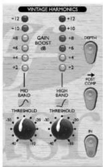
VINTAGE HARMONICS +12 +10 +8 +6 +4 +2 +12 GAIN BOOST dr +5 +4 +2 HD BAND THRESHOLD -30 -26 -20 -16 -12 -8 -4 -2 +10 +8 +4 +2 DEPTH POST COMP THRESHOLD NIN (switch) - Switches the VINTAGE HARMONICS into the signal path. When engaged, the red LED in the switch cap is lit.
MID BAND THRESHOLD (knob) - This allows boosting of the mid frequency signals. The amount of boost is controlled by the MID BAND THRESHOLD knob in relation to the level of the audio passing through the circuit. A low threshold will result in a larger Mid Frequency Harmonic boost. The circuit peaks at 3k.
HIGH BAND THRESHOLD (knob) - This allows boosting of the high frequency signals. The amount of boost is controlled by the HIGH BAND THRESHOLD knob, in relation to the level of the audio passing through the circuit. A low threshold will result in a larger High Frequency Harmonic boost. The circuit peaks at 18k.
GAIN BOOST (LED meters) - This shows the Mid (left meter) and High (right meter) bands' relative boosts, as controlled by the threshold knobs.
DEPTH (switch) - This controls the relative depth of the boost of the harmonic frequencies. Engaging the switch (in) causes more obvious harmonic enhancement, disengaging the switch (out) reduces makes the enhancement more subtle.
POST COMP (switch) - When engaged (in), inserts the VINTAGE HARMONICS section after the OPTICAL COMPRESSOR section in the signal path. When disengaged (out), VINTAGE HARMONICS occur pre-compressor. Placing the VINTAGE HARMONICS post-compressor means that you are able to stop the affected harmonics changing the way the compressor responds. If you prefer to have the VINTAGE HARMONICS affect the way the compressor responds, disengage the POST COMP switch, placing the VINTAGE HARMONICS section before the OPTICAL COMPRESSOR.
OPTICAL COMPRESSOR
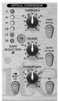
The OPTICAL COMPRESSOR acts like an automatic volume control, turning down the volume of a signal if it gets too loud. This reduces variation between loud and quiet passages, as it automatically reduces the gain when the signal exceeds a given volume, defined as the threshold. Using the OPTICAL COMPRESSOR helps to 'even out' a performance, stopping a vocal from chipping and/or disappearing in the mix.
text_image
OPTICAL COMpressor -3 -6 -9 -12 -15 -20 -3 -6 -9 -12 -15 -20 THRESHOLD -26 -28 -35 -45 -49 HARD RATIO GAIN REDUCTION 0.3 0.1 0.1 RELEASE SLOW ATTACK AUTO MAKELIP GAIN POST PO +3 +15 +18 +18 +18 +18IN [switch] - Switches the OPTICAL COMPRESSOR into the signal path. When engaged, the red LED in the switch cap is lit.
ENGLISH
THRESHOLD (knob) - Determines when the OPTICAL COMPRESSOR starts to compress the signal - the lower the threshold, the more the signal is compressed. The signal is only compressed when it exceeds the threshold, so quieter passages maintain their natural dynamic range, whilst loud passages (that exceed the threshold) are compressed.
MAKEUP GAIN (knob) - Sets the output volume of the compressed signal. Since compressing a signal makes it quieter, use the MAKEUP GAIN control to restore the signal to its original volume. Compare the volume of the original and the compressed signal by using the IN switch to switch the OPTICAL COMPRESSOR on and off.
RELEASE (knob) - Determines the time taken for the gain reduction to return to normal once the signal drops below the threshold. The faster the release, the louder the signal appears to be.
GAIN REDUCTION (LED meter) - Displays the amount of gain 'lost' due to compression. Since compression reduces the volume of the signal, the meter drops as compression is applied: for example, a 9 dB drop shows as -9 on the meter.
HARD RATIO (switch) - When engaged (in), selects a higher compression ratio, which gives a very flat, compressed sound. Do not use the HARD RATIO switch if you want to maintain most of the original dynamics.
SLOW ATTACK (switch) - When engaged (in), selects a slower attack time, which allows more of the transient peaks of the signal through the compressor. This can help retain a sense of the original signal's dynamics when compressing heavily. For example, this can be useful to allow compression of a snare drum without losing the initial 'crack' of the drum stick striking the snare skin.
POST EQ (switch) - When engaged (in), inserts the OPTICAL COMPRESSOR after the VOICE OPTIMISED EQ section in the signal path. When disengaged (out), compression occurs pre-EQ. Placing the compressor after the EQ means that you are able to affect the way the compressor responds by making changes to EQ settings. If you prefer to have the compressor act independently from the EQ, disengage the switch, placing the compressor section before the EQ section.
Note that the user has control of the position of both the OPTICAL COMPRESSOR versus EQ section AND the VINTAGE HARMONICS versus OPTICAL COMPRESSOR section. Hence four different signal flow arrangements are possible;
- VH → COMP → EQ – disengage both the VINTAGE HARMONICS section's POST COMP switch AND the OPTICAL COMPRESSOR's POST EQ switch.
- VH → EQ → COMP - disengage the VINTAGE HARMONICS section's POST COMP switch, engage the OPTICAL COMPRESSOR's POST EQ switch.
- COMP → VII → EQ - engage the VINTAGE HARMONICS section's POST COMP switch, disengage the OPTICAL COMPRESSOR's POST EQ switch.
- EQ → COMP → VH - engage both the VINTAGE HARMONICS section's POST COMP switch ANDd the OPTICAL COMPRESSOR's POST EQ switch.
TUBE SOUND
The TUBE SOUND processor simulates the sound of valve (tube) and tape distortion. The TUBE SOUND circuit is a FFT-based circuit, and operates in 3 stages. As you turn the pot clockwise you add firstly 2^nd order harmonics, then 2^rd + 5^rd order, and finally 2^rd + 3^rd + 5^th order harmonics (fully clockwise).
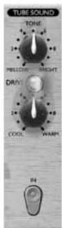
IN (switch) - Switches the TUBE SOUND section into the signal path. When engaged, the red LED in the switch cap is lit.
TONE (knob) - Determines which frequencies are affected. In the BRIGHT position (fully clockwise), the whole signal is saturated; as you rotate the control counter-clockwise towards the MELLOW position, it introduces a low pass filter, so that only the frequencies below the cut-off frequency (5 kHz) are affected by the TUBE SOUND processing.
ENGLISH
DRIVE (knob and LED) - Determines how much saturation is applied. As you rotate the drive control clockwise from COOL to WARM, you progressively increase the amount of overdrive applied to the signal, adding harmonic-rich peak compression, and creating a more 'rounded' tone. As the signal level increases, so more harmonics are created. The DRIVE LED provides a visual indication of the amount of distortion being applied, by changing colour from blue, (no distortion,) through green, to red (high distortion).
VOICE OPTIMISED EQ
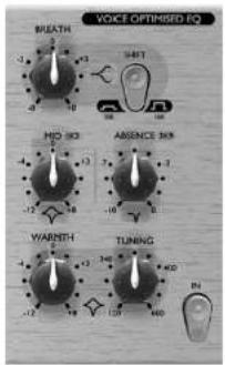
The VOICE OPTIMISED EQ is a sophisticated tone control that boosts or cuts selected frequency bands and so modifies the tonal quality of the input signal. It can be used correctly (to fix problems with the original sound) or creatively (to enhance a signal and help a track stand out in a mix).
text_image
VOICE OPTIMISED EQ BREATH MID-3D ABSENCE 3KB WARNTH TUNINGIN (switch) - Switches the VOICE OPTIMISED EQ into the signal path. When engaged, the red LED in the switch cap is lit.
BREATH (knob) - Boosts or cuts the high frequencies in the signal. Adjust the Breath control to accentuate or reduce the breathy part of a vocal. The SHIFT switch determines the frequencies that are affected.
SHIFT (switch) - Determines the shelving frequency for the BREATH EQ band. With the SHIFT switch disengaged (out) the BREATH control affects frequencies above 16kHz; with the switch engaged (in) it affects frequencies above 10kHz.
MID (knob) - Boosts or cuts the 'edge' and high mid of the voice. This circuit uses a bell-shaped EQ curve centred on 1.3 kHz.
ABSENCE (knob) - 'This control allows you to reduce the volume of the frequencies that make a vocal sound coarse or harsh. This circuit uses a bell-shaped EQ curve centred on 3.9 kHz, which allows 0 dB (fully clockwise) to 10 dB (fully counter-clockwise) of cut to be applied.
WARMTH (knob) - Boosts or cuts low frequencies in the signal. The frequencies that are affected are determined by the TUNING control. Cutting frequencies with the WARMTH control affects a narrower range of frequencies than when boosting. The Q value is 0.7 for boost (knob pointing to the right) and 2.5 for attenuation (knob pointing to the left.)
TUNING (knob) - Determines which frequencies are affected by the WARMTH control - in general lower frequencies affect male voices and higher frequencies affect female voices. The range of frequencies which can be affected in this band range from 120 Hz (knob fully counter-clockwise) to 600 Hz (knob fully clockwise).
DE-ESSER
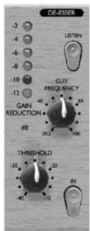
The DE-ESSER lets you remove excessive sibilance from a vocal performance. (A sibilant sound is one in which the "css" sound is over-emphasised.) The VoiceMaster Pro uses the phase cancellation de-essing circuit from Focusrite's flagship ISA 430 to neatly eliminate a very narrow band of frequencies (user-definable, see 'CUT FREQUENCY' below,) centred around the sibilant frequency.
text_image
DE-855R -2 -4 -6 -8 -10 -12 -12 CUT FREQUENCY GAIN REDUCTION 0 dB 30 24.1 10K THRESHOLD 30 23 9VENGLISH
IN (switch) - Switches the DE-ESSER into the signal path. When engaged, the red LED in the switch cap is lit.
THRESHOLD (knob) - Determines how much gain reduction is applied to the selected frequency (as determined by the CUT FREQUENCY control, described below). The lower the threshold, the more de-essing is applied.
GAIN REDUCTION (LED meter) - Displays the amount of gain reduction applied to the selected frequency, in dB. Range is -2 dB to -12 dB.
CUT FREQUENCY (knob) - Determines the frequency to be removed. Adjust the CUT FREQUENCY control to select the sibilant frequency to be removed. Range is 2.2 kHz to 10 kHz (fully clockwise).
LISTEN (switch) - Allows you to monitor the DE-ESSER sidechain. When engaged (in), the sidechain signal is fed to the output of the VoiceMaster Pro. This allows you to use the CUT FREQUENCY control to solo the 'essy' frequency range of the signal very easily - simply adjust the CUT FREQUENCY until the sidechain signal is as 'essy' as possible, then disengage the LISTEN switch and adjust the threshold (whilst observing the GAIN REDUCTION meter) to apply the DE-ESSER process as required.
When using the DE-ESSER, ensure that you do not set the threshold too low, or you will affect too much of the vocal. When you have the threshold set correctly, the effect of the DE-ESSER should not sound obvious until you compare the affected signal with the original signal. (Toggle the IN button to compare them.)
OUTPUT LEVEL
text_image
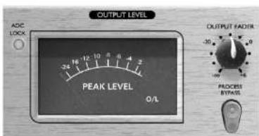
OUTPUT LEVEL ADC LOCK - 34 16 -12 10 8 4 2 PEAK LEVEL 0/L OUTPUT FADS -36 0 - 100 16 PROCESS BYPASSOUTPUT FADER (knob) - The OUTPUT FADER is used to set the correct output level from the VoiceMaster Pro to suit the input level of the next unit in the chain (such as a PC sound card or DAT/CD recorder). When setting the OUTPUT
FADER, always start quietly and increase the output level until you reach the correct level – do not start with the output level set high, as it may damage the next unit in the chain. Be careful that peak signals do not exceed 0 dBfs if the internal A/D is used; the output level should be set so that it peaks close to -2 dBfs, allowing a small safety margin. Always check the receiving device to ensure that it is not registering overload.
If inserting the VoiceMaster Pro into a channel of a mixing console, set the OUTPUT FADER at 0, and perform any output level adjustments using the console's fader.
PEAK LEVEL METER - The inclusion of a custom VU meter in the VoiceMaster Pro's output section allows the user to accurately monitor the levels being sent to external analogue or digital equipment from the VoiceMaster Pro's analogue and digital outputs. The peak-reading meter displays levels from -24 dBfs to 0 dBfs. An overload LED shows when levels are excessive - if this lights, reduce the level of signal being fed to the outputs using the controls in the EQ and compression section, or using the output level control.
PROCESS BYPASS (switch) - This switch allows you to globally bypass all the processing sections in the VoiceMaster Pro, and is useful for comparing the level/sound of processed and unprocessed signals.
LATENCY-FREE MONITORING
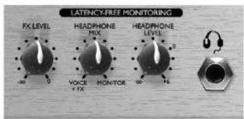
The LATENCY-FREE MONITORING section is used in conjunction with the HEADPHONE socket to provide flexible monitoring of the signal being recorded. Latency is a major problem when recording to e.g. a digital system via a sound card. If the signal to be monitored has to pass through the digital recorder and then be relayed back for external monitoring, significant delays may occur, making it difficult or impossible to sing, speak or play in time with the other tracks already recorded. The VoiceMaster Pro's LATENCY-FREE MONITORING section allows the user to monitor in stereo directly from the monitoring section, before passing through the digital recording system. Thus latency is eliminated and the recording artist can listen to other tracks already recorded, whilst speaking, singing or playing to those tracks in perfect time.
text_image
LATENCY-FREE MONITORING FX LEVEL HEADPHONE MIX HEADPHONE LEVEL VOICE + FX MONITOR -0 -1 -2ENGLISH
FX LEVEL (knob) - This controls the level of the FX RETURN input on the rear panel. For example, reverb could be applied from an external processor using the (mono) FX SEND and (stereo) FX RETURN connectors, so that a vocalist can hear his/her vocal with reverb whilst recording.
HEADPHONE MIX (knob) - This controls the mix sent to the HEADPHONE output, and allows you to mix between VOICE & FX (a combination of the signal sent to the main output plus the FX RETURN signal, as controlled by the FX LEVEL knob) and MONITOR (the signal from the EXT MONITOR INPUTS).
HEADPHONE LEVEL (knob and TRS jack socket) - This knob controls the level sent to the stereo HEADPHONE jack.
EXT MONITOR INPUTS (rear fascia) - These inputs are provided on balanced (+4 dBu) quarter inch TRS jacks. They allow routing of your main stereo mix outputs (e.g. from a digital recording system) to the VoiceMaster Pro's LATENCY-FREE MONITORING section. This means that you can monitor both the stereo mix already recorded, AND the processed signal from your VoiceMaster Pro at the same time. (So you can leave your VoiceMaster Pro permanently rigged up in your recording system for tracking, whilst also allowing you to monitor the output from your main DAW (e.g. finished stereo mix with VoiceMaster Pro-processed, recorded vocals.) See the LATENCY-FREE MONITORING section above.
MONITOR OUTPUTS (rear fascia) - These outputs are provided on balanced, (+4 dBu) quarter inch TRS jacks. They allow routing of your main stereo mix from e.g. a digital recording system (DAW etc) to a pair of monitor speakers. Note that these monitor outputs are separate from the headphone bus/latency-free monitoring section, so the outputs relay only signal that is fed from the Ext. Monitor Inputs. (The headphone bus allows monitoring of the VoiceMaster Pro-processed signal when tracking.)
DIGITAL OUTPUT OPTION
text_image
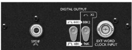
DIGITAL OUTPUT SPDIF JL JL 44K 88K2 JL 48K 96K EXT WORD CLOCK INPUTIn addition to the analogue outputs, a high quality 24 bit, 128x over-sampled digital output may be fitted as an option, which can operate at sample frequencies of 44.1, 48, 88.2 or 96 kHz. All of the following functions are available on the rear panel when this option is fitted:
ADC EXT INPUT (rear panel) - This quarter inch jack (balanced, 0 dBfs to +22 dBfs) line level input on the rear panel allows an additional signal to be routed through the 'spare' channel of the stereo digital output. This input always routes external signal to the right hand channel of the A/D converter. For example, two VoiceMaster Pro units could be used simultaneously, with a single digital output option. The first VoiceMaster Pro unit would feed the left channel of the A/D card installed. The second VoiceMaster Pro unit output would be connected to the ADC EXT' INPUT', and would feed the right channel of the same A/D card, allowing two channels of A/D conversion.
S/PDIF OUTPUT - This 24 bit output is S/PDIF format on an RCA phono connector. If 16 bit resolution is required, the receiving device should either the 24 bit signal to achieve 16 bit performance.
SAMPLE FREQUENCY (switch) - Two switches give a choice of four sample frequencies as marked on the rear panel. The left-hand switch selects between 44.1kHz (switch in) and 48kHz (switch out), and the right-hand switch doubles the selected frequency, providing for 88.2 and 96kHz sample frequencies.
EXT WORD CLOCK INPUT - If an external Wordclock source is fed to the BNC connector, the VoiceMaster Pro will attempt to synchronise to it. When the unit is correctly locked to the external clock source the ADC LOCK LED (on the front panel) will light to indicate correct operation. (The ADC LOCK LED should light continuously. If this flickers it indicates bad jitter on the synchronising signal, requiring investigation of the Wordclock-generating device.)
Fitting Instructions
See the separate A/D option owner's manual for instructions on how to fit the A/D option.
OBTAINING GOOD QUALITY SOUND
MICROPHONE POSITIONING
Recording vocals requires a different technique to that used when mixing live vocals, where the vocalist usually sings with the microphone touching his or her lips. In a studio recording situation it is usually desirable for the vocalist to be at least 50 cm away from the microphone. If this affects the vocal performance, (or if the vocal sounds weak), allow the vocalist to move closer to the microphone, but use a pop shield. It may also be necessary to use the VoiceMaster Pro's HIGH PASS FILTER (√) to remove excessive bass tip-up, caused by the vocalist singing too close to the microphone (the so-called 'proximity effect').
USING COMPRESSION
If the vocalist is having difficulty staying a constant distance from the microphone, the recorded performance will get softer and louder as the distance from the microphone varies. To even out variations in level, use the OPTICAL COMPRESSOR to compress the signal.
USE OF EFFECTS PEDALS
When using the INSTRUMENT INPUT, connect any effects pedals in-line, before the VoiceMaster Pro's INSTRUMENT INPUT. The output (whether analogue or digital) from the VoiceMaster Pro should be connected directly to your recorder.
SPOKEN WORD
When recording the spoken word, use the WARMTH control in the VOICE OPTIMISED EQ to maximise depth, resonance and power. This is the sort of vocal sound favoured by many radio broadcasters.
BACKING VOCALS
Backing vocals are normally heavily compressed, since you want them to have a uniform presence without volume variations. Engage the HARD RATIO switch in the OPTICAL COMPRESSOR and adjust the THRESHOLD so that GAIN REDUCTION meter shows between 9 and 15 dBs of compression. To avoid the backing vocals becoming too fat and overpowering, use the WARMTH control in the VOICE OPTIMISED EQ to reduce the amount of bass in the vocals.
CORRECTING PROBLEMS
MUDDY
Use the WARMTH control in the VOICE OPTIMISED EQ to remove some of the low frequencies. Solo the track, set the WARMTH control on full cut, and adjust the TUNING control until the vocal sounds more balanced. Then listen to the vocal in the context of the mix, and adjust the amount of cut on the WARMTH control to
ENGLISH
give the correct sound in context. If necessary at this time, you may also need to increase the amount of BREATH.
FLAT
Increase the MID control in the VOICE OPTIMISED EQ. You may also need to add some BREATH, and/or maybe some WARMTH (if the result has too much top end). However, beware of overdoing the effect by adding too much.
HARSH
Use the ABSENCE control in the VOICE OPTIMISED EQ. This creates a natural dip in the harsh frequencies. You may also want to add some WARMTH, and if necessary, remove some MID or BREATH.
LOST IN THE MIX
Increase the MID control in the VOICE OPTIMISED EQ. Avoid using too much WARMTH on the vocal, as you will be boosting frequencies in the same frequency range as many of the instruments on the track.
SIBILANT
If sibilant components (unpleasant "s" sounds) are standing out, use the DE-ESSER to make them sound more natural, as described in FACILITIES AND CONTROLS.
MIX LACKS CHARACTER
When mixing down, don't be afraid to be outrageous. In pop, for example, the vocal is invariably heavily compressed, and often equalised. In the TUBE SOUND section, try using the DRIVE control (with the TONE control in its BRIGHT position) to give one channel an analogue sound. Or reduce the TONE control to create a low fidelity effect. Also try using the VINTAGE HARMONICS section to give the vocal a classic 1970s enhancement effect (see page 6 for more details).
REVERB OR DELAY PROBLEMS
Sometimes, reverb or delay can sound too lively and tends to "zing" – this is caused by sibalance in the voice. If you find this with the vocals you have recorded, you can try using the DF-ESSER to fix the problem, by heavily de-essing the signal that will be sent to the external effects unit. Then, at the recorder, mix the dry signal (from the PRE DE-ESSER output XLR socket on the back of the VoiceMaster Pro) with the wet signal from the effects unit.
FIXING BLEED ('SPILL')
If there is noticeable bleed from other instruments off the vocalist's headphones, remove it when mixing down using the OPTICAL EXPANDER. Note that the more you compress a track, the more noticeable any bleed will become.
A BEGINNER'S GUIDE TO COMPRESSION
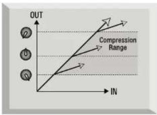
Compressors are probably the most widely used signal processors in the audio industry. A compressor can be thought of as an automatic volume control. Once the volume of the signal exceeds a certain level (called the 'threshold'), the compressor reduces the gain (in other words, 'turns the volume down'), causing the signal to be less loud than it would otherwise have been.
text_image
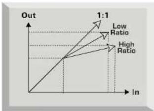
OUT Compression Range INThe amount by which the compressor reduces the gain is determined by the 'ratio'. The ratio is conventionally expressed as a numerical value, e.g. '4:1', which represents the amount by which the gain is reduced when the volume of the signal rises above the threshold.
line
| In | Out | |---|---| | Low Ratio | 1:1 | | High Ratio | 1:1 |ENGLISH
Let's take an example with some real numbers. If the threshold is set to -10 dB and the ratio is set to 4:1, any signal whose level exceeds -10 dB needs to rise in level by 4 dB for the output of the compressor to rise by 1 dB. Therefore an input signal with a peak at -6 dB (which is 4 dB above the threshold) would emerge from the compressor with a peak at -9 dB (1 dB above the threshold). Signal levels below the threshold are unaffected, so if the signal in the above example varied between -20 dB and -6 dB before entering the compressor, it will vary between -20 and -9 dB after being compressed. Its dynamic range (the difference between the quietest and loudest parts of the signal in dB) is reduced from 14 dB to 11 dB.
Compression results in any variations in the volume of the signal (in other words, the signal's dynamic range) being reduced - the amount of this reduction is determined by the threshold (the level above which the gain is reduced) and the ratio (the amount by which the gain is reduced.) Higher ratios are referred to as hard ratios; lower ratios are called soft ratios.
Because compression causes a reduction in volume level of loud signals, gain must be applied after the compressor to bring the overall volume level back up, so that the maximum volume before the compressor is the same as that after the compressor. This is called 'make-up gain', and is necessary so that the maximum level of the signal is always the same, for correct level matching with any further processing or other equipment.
Once 'make-up gain' has been applied, the part of the signal that was lower than the threshold volume (and hence not compressed) will now be louder than it was before the compressor. This will cause any compressed instrument to sound louder. One use for this phenomenon is to give guitars more sustain.
In most pop music, the backing instruments (such as drums, bass guitars, rhythm guitars etc) tend to be compressed heavily (using a fairly hard ratio and low threshold), so that they remain at a consistent volume level throughout the track. This will provide a solid backing, without occasional drum hits or bass notes poking through (or disappearing from) the mix untidily.
A soft ratio tends to be used on instruments such as lead guitars or vocals that 'sit' on top of the mix. In this situation it is often desirable to preserve more of the dynamics of the original performance, to retain more expression. A reduction in variation of volume level is still required (for the reasons mentioned above), but not to the same extent.
ENGLISH
The other controls included on most compressors are attack and release.
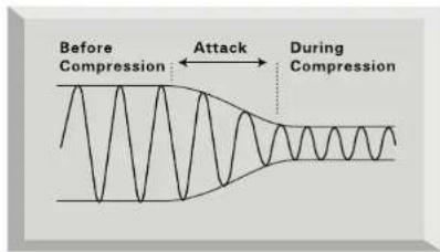
Attack determines the speed at which the compressor starts to reduce the gain once the threshold has been exceeded. Think of it as the time taken to turn the volume down. Very short attack times mean the compressor 'kicks in' very quickly – short attack times are typically used for vocals in order to keep the levels under strict control. Longer attack times mean more of the original signal's attack dynamics are preserved – this is a good way of keeping percussive and guitar sounds exciting and punchy.
Release determines the speed at which the compressor stops acting once the signal drops below the threshold. Think of it as the time taken to turn the volume back up.
text_image
Before Compression Attack During Compression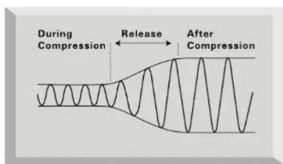
text_image
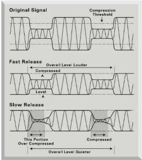
During Compression Release After CompressionShort release times mean the compressor very quickly returns the signal to its normal level. This can produce a 'pumping' sound, where the changes in volume are very audible. Depending on the style of music, this can be undesirable, or a useful creative effect.
Longer release times may mean that parts of the signal below the threshold end up being compressed, or that the gain doesn't have a chance to return to normal before the next 'above threshold' sound – remember that the compressor works on the whole signal. See the diagram below:
text_image
Original Signal Compression Threshold Fast Release Overall Level Louder Compressed Level Slow Release This Portion Over Compressed Compressed Overall Level QuieterA BEGINNER'S GUIDE TO EQUALISATION
Equalisers are also widely used in the audio industry, and are effectively just tone controllers, though a bit more involved than those found on most hi-fi systems. They allow you to cut or boost certain frequencies or frequency bands within the audio signal.
There are two main applications for using equalisation, or EQ (as it's more commonly known). The first is 'creative' use. This involves enhancing a sound that is already present in some desirable way. Typical examples might involve boosting lower frequencies to give more depth, or boosting the high frequencies to give more of a 'sparkle' to a sound. Because the precise frequencies that give these qualities will vary from instrument to instrument, it is sometimes necessary to be able to adjust the point at which frequencies will be cut or boosted by the EQ, as well as the amount of cut or boost.
The other main application of EQ is 'corrective' use. This involves using EQ to remove or reduce the level of unwanted frequencies. Here are a few examples of 'corrective' use of EQ;
Cutting low frequencies to reduce 'proximity effect', where low frequencies have been over-emphasised as a result of close miking with certain types of microphone. Cutting the frequencies that may cause a vocal to sound boxy, nasal or harsh. Cutting the frequencies that may cause a drum to ring undesirably.
Parametric EQ (such as the WARMTH control) allows the user to focus in on a specific band of frequencies in order to cut or boost them. This is particularly useful for 'corrective' applications of EQ as the offending frequency may be honed in on, and its gain reduced. It is also useful for 'creative' applications, for example giving warmth or presence to a vocal.
Check out www.focusrite.com for links to more information on the subjects of compression and EQ.
ENGLISH
FREQUENTLY ASKED QUESTIONS
Q. Is the VoiceMaster Pro only suitable for recording vocals in musical applications?
A. No, the VoiceMaster Pro is suitable for recording many other sound sources too, such as electric guitars and bass (via its INSTRUMENT INPUT). It is also ideal for applications such as recording the spoken word, live sound applications, radio and TV broadcast, dubbing, post production and so on.
Q. Is the VoiceMaster Pro a Class A device, and why is that important?
A. Yes, the VoiceMaster Pro is a Class A device. Why? Class A is a type of amplifier design in which you have standing DC current running through your amplifier circuits all the time. As the signal comes along you vary what you're taking from that, rather than switching between supplying a positive current for one half of the waveform and a negative current for the other half. This results in the ability to represent audio in a linear (distortion free) manner all the way through the circuit. Cheaper processors use IC amplifiers which run close to Class B and don't have the same standing DC current, which means the transistors inside the chips switch off and on, inevitably resulting in less linear performance.
Q. My VoiceMaster Pro gets quite hot when in use. Should I be worried about this?
A. No. This is a result of the high quality Class A circuitry inside your VoiceMaster Pro, which has been designed to dissipate heat. As a precaution, it is wise to rack hotter units lower down your rack than cooler units. If space is available, fit a blank panel between units to allow extra ventilation.
Q. What is the difference between +4 dBu and -10 dBV?
A. These are different signal operating levels. +4 dBu usually refers to professional equipment and -10 dBV usually refers to semi-professional or consumer equipment. It is important to make sure that any two or more devices connected to each other are operating at the same signal level. If the +4 dBu output of a device feeds the -10 dBV input of another device, this may cause the second device to overload. Alternatively, if the -10 dBV output of a device feeds the +4 dBu input of another device, the second device may receive a signal level which is too low (i.e. too quiet). -10 dBV devices are usually connected using a mono 1/4" jack. This is known as an 'unbalanced' connection. +4 dBu devices are usually connected using a TRS (stereo) 1/4" jack, or XLR. This is known as a 'balanced' connection.
Q. Should I use balanced connectors with my VoiceMaster Pro?
A. Yes, where possible. The line level analogue input is balanced, operating at +4 dBu. The VoiceMaster Pro provides both balanced (+4 dBu) and unbalanced (-10 dBV) output connectors. See the 'Rear panel connections' section on page 3 for more information on connecting the analogue line level inputs and outputs.
Q. Does the VoiceMaster Pro have the same kind of spectacular bandwidth that has given the Red and ISA range units their reputation for 'open-ended' sound?
A. Yes. 'The audio bandwidth of the VoiceMaster Pro is 10 Hz to 200 kHz!
Q. Can I take my VoiceMaster Pro with me when I travel internationally? A. It depends. There are three versions of the VoiceMaster Pro mains transformer. One is suitable for use in North America, one in Japan (both with mains voltages in the 100-120V range). The third version is designed for use in the UK and Europe, with mains voltages in the 200-240V range. If you buy a VoiceMaster Pro in a particular territory, it will be configured for ONLY that territory's mains voltage range. For example, if you're travelling from the USA to the UK, you CANNOT use your US model VoiceMaster Pro. But if the mains voltage in the country you're visiting is in the same range, you can use the VoiceMaster Pro with no problems - so taking a VoiceMaster Pro from Germany to France, for example, would be fine.
Q. Is there an optional digital input card?
A. No, because all the processing in the VoiceMaster Pro is entirely analogue - so even if there were a digital input, the digital signal would have to immediately pass through a D/A converter to allow processing!
Q. Why is the 24 bit 96kHz specification important?
A. An A/D converter works by sampling the audio waveform at regular points in time, and then quantising those values into a binary number, which relates to the number of bits specified. The quantised signal must then be passed through a D/A converter before it becomes audible. In simple terms, the D/A essentially 'joins the dots' plotted by the A/D converter when the signal was first converted to digital. The number of dots to join, combined with how little those dots have been moved, determines how accurate the final signal will be compared to the original. The greater the sample rate and bit rate, the more accurate the whole digital process is. So 24 bit/96 kHz performance will ensure more accurate digital transfer of your audio information compared to 16 bit/44.1kHz standards. This is especially important if further digital signal processing is to be applied to the signal once converted to digital, as any mathematical operations taking place on the data (for example as a result of a gain change, or dynamic effect process) may result in quantisation and rounding errors. The higher the resolution of the digital data, the smaller the audible effect of these errors.
Q. Can I retrofit a digital board to an analogue VoiceMaster Pro at a later date?
A. Yes, and you can do it yourself - it can easily be retro-fitted by the customer without any soldering etc, just a few screws to undo, and one clip-connector to join to the main PCB.
Q. What is Wordclock?
A. Whenever multiple digital audio devices are connected together digitally, all the devices must be Wordclock synchronised to avoid data transfer problems. All devices must send and receive their data at the same sample rate (e.g. 44.1kHz) but they must also have their internal clocks running in sync. This ensures that all units send, receive and process their data streams simultaneously. Failure to achieve this will mean a drastic reduction in audio quality, and other unwanted audible artefacts, such as pops and clicks, may occur. At a sample rate of 44.1kHz for example, there are 44,100 spaces every second that need to have samples inserted. If there is a slight drift in one of the clocks, some of those samples will be 'missed'/will move forward one place, which results in distortion.
To avoid such problems, every digital system needs to employ Wordclock. One unit should be designated the 'Wordclock master', and all others should be designated 'Wordclock slaves'. Setting this up is often simple, since most digital transfer formats include embedded Wordclock data (e.g. S/PDIF, AES/EBU, ADAT). Where this is not the case (e.g. TDIF), Wordclock can be provided via a separate Wordclock connection. Note that timecode synchronisation (e.g. SMPTE) is different to Wordlock synchronisation, but equally important. Timecode enables recording and playback devices to run in sync with one another, and carries a regular series of absolute time values (hrs:min:secs:frames). The two timing systems are quite independent.
TROUBLESHOOTING
No LEDs illuminate
• Is the POWER switched on?
- Is the correct mains voltage being used for your unit? If not, the fuse may blow, requiring the correct fuse to be refitted.
No output when using the MIC INPUT
• Is the power switched on?
- Is the LINE switch on the front panel switched out?
- Is the INPUT GAIN set correctly? (See 'Facilities and Controls' section for details.)
- For microphones that require phantom power, is the +48V switch engaged? (If you are unsure whether your microphone requires phantom power, check the user guide for your microphone.)
No output when using the LINE INPUT
• Is the power switched on?
- Is the LINE switch on the front panel switched in?
- Is the INPUT GAIN set correctly? (See 'Facilities and Controls' section for details.)
No output when using the INSTRUMENT INPUT
• Is the power switched on?
- Is the LINE switch on the front panel switched out?
- Is the INPUT GAIN set correctly? (See 'Facilities and Controls' section for details.)
ENGLISH
The OPTICAL COMPRESSOR is not working
- Is the compressor section's IN switch engaged?
- Is the INPUT GAIN set correctly? If set too low, the signal level may not be high enough to activate the compressor.
- Is the THRESHOLD control set correctly? (If set too high, the input level may not reach the threshold at which compression starts.)
• Is the PROCESS BYPASS switch engaged?
The VOICE-OPTIMISED EQ is not working
- Is the EQ section's IN switch engaged?
- Has some cut or boost been applied?
• Is the PROCESS BYPASS switch engaged?
No Wordclock lock
- Is your external Wordclock source transmitting Wordclock?
Is the sample frequency set to match that of the Wordclock-transmitting device?
Is a Wordclock cable connected if required? (See 'What is Wordclock?', page 16.)
No output from the digital output option
• Is the sample frequency set correctly?
• Is the receiving device set to receive at 24 bit?
CONTACTING US
If have any questions about your VoiceMaster Pro, or are continuing to have difficulty, you can email us for help at tech@focusrite.com. Alternatively, telephone us on +44 (0)1494 462246, or contact your local distributor (see listing at the back of this manual).
INHALT
INHALT....18
DISCRETE CLASS A PRE-AMP 21
OPTICAL EXPANDER....22
VINTAGE HARMONICS....22
OPTICAL COMPRESSOR....23
TUBE SOUND 24
STIMMENOPTIMIERTER EQ....25
DE-ESSER....25
AUSGANGSSEKTION 26
LATENZFREIES MONITORING 26
OPTIONALER DIGITALER AUSGANG 27
BESTE SOUNDERGEBNISSE....27
BEHEBEN VON PROBLEMEN....28
text_image
Eosurite Eosurite Audio Engineering Ltd ADC EXT INPUT OUT POWER INPUT OUTPUT INPUT ACR EXT INPUT ACR OUTPUT OUTPUT OUTPUT ACR EXT INPUT ACR OUTPUT OUTPUT OUTPUT ACR EXT INPUT ACR OUTPUT OUTPUT OUTPUT ACR EXT INPUT ACR OUTPUT OUTPUT OUTPUT ACR EXT INPUT ACR OUTPUT OUTPUT OUTPUT ACR EXT INPUT ACR OUTPUT OUTPUT OUTPUT ACR EXT INPUT ACR OUTPUT OUTPUT OUTPUT ACR EXT INPUT ACR OUTPUT OUTPUT OUTPUT ACR EXT INPUT ACR OUT OUTPUT OUTPUT ACR OUT OUTPUT ACR OUT OUTPUT ACR OUT OUTPUT ACR OUT OUTPUT ACR OUT OUTPUT ACR OUT OUTPUT ACR OUT OUTPUTDEUTSCH
DISCRETE CLASS A PRE-AMP
text_image
DE-ESSER -2 -4 -6 -8 -10 -12 -2 -4 -6 -8 -10 -12 LISTEN CUT FREQUENCY GAIN REDUCTION dB 10K 10K 10K 10K 10K 10K 10K 10K 10K 10K 10K 10K 10K 10K 10K 10K 10K 10K 10K 10K 10K 10K 10K 10K 10K 10k 10k 10k 10k 10k 10k 10k 10k 10k 10k 10k 10k 10k 10k 10k 10k 10k 10k 10k 10k 10k 10k 10k 10k 10k 10Ktext_image
OUT Compression Range INtext_image
Before Compression Attack During Compression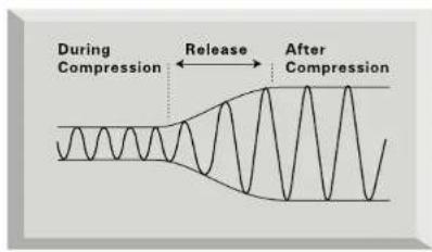
text_image
During Compression Release After Compressiontext_image
Original Signal Compression Threshold Fast Release Overall Level Louder Compressed Level Slow Release This Portion Over Compressed Compressed Overall Level QuieterEINFÜHRUNG EQ
CORRECTION DES PROBLÈMES....44
GUIDE D'INTRODUCTION À LA COMPRESSION ....45
GUIDE D'INTRODUCTION À L'ÉGALISATION....47
QUESTIONS COURANTES....47
ASSISTANCE....49
POUR NOUS CONTACTER....49
INFORMATIONS RELATIVES À LA SÉCURITÉ
SECTION "TUBE SOUND"
text_image
VOICE OPTIMISED EQ SPATH MID-M3 ABSENCE-M3 WARMEN TUNINGtext_image
OUT Compression Range INtext_image
Before Compression Attack During Compression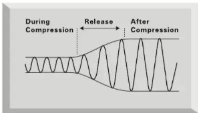
text_image
During Compression Release After Compressiontext_image
Original Signal Compression Threshold Fast Release Overall Level Louder Compressed Level Slow Release This Portion Over Compressed Compressed Overall Level QuieterGUIDE D'INTRODUCTION À L'ÉGALISATION
GUIDA ALLA COMPRESSIONE....61
text_image
OUT Compression Range INtext_image
Before Compression Attack During Compression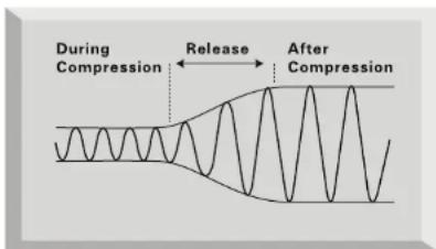
text_image
During Compression Release After Compressiontext_image
Original Signal Compression Threshold Fast Release Overall Level Louder Compressed Level Slow Release This Portion Over Compressed Compressed Overall Level QuieterDISCRETE CLASS A PRE-AMP 69
OPTICAL EXPANDER....70
VINTAGE HARMONICS....70
OPTICAL COMPRESOR....71
TUBE SOUND 72
VOICE OPTIMISED EQ....73
DE-ESSER....73
OUTPUT LEVEL 74
MONITOR LATENCY-FREE....74
SALIDA DIGITAL OPCIONAL 75
OBTENIENDO BUENA CALIDAD DE SONIDO....76
DISCRETE CLASS A PRE-AMP
PERDIDO EN LA MEZCLA
text_image
OUT Compression Range INtext_image
Before Compression Attack During Compression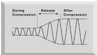
text_image
During Compression Release After Compressiontext_image
Original Signal Compression Threshold Fast Release Overall Level Louder Compressed Level Slow Release This Portion Over Compressed Compressed Overall Level Quieter- Gain range = 0 dB to 60 dB continuously variable.
• Input Impedance = 1K4 Ω from 10 Hz to 200 kHz. - EIN = 128 dB measured at 60 dB of gain with 150 Ω terminating impedance and 20 Hz/22 kHz bandpass filter.
- THD at minimum gain (0 dB) = 0.0004% measured with +16 dBu input signal and with a 20 Hz/22 kHz bandpass filter.
- THD at maximum gain (60 dB) = 0.003% measured with a -36 dB input signal and with a 20 Hz/22 kHz bandpass filter.
- THD at maximum input level (26.5 dBu) = 0.005% measured with a 20 Hz/22 kHz bandpass filter.
• Frequency response at minimum gain (0 dB) = flat at 10 Hz and -2 dB down at 200 kHz. - Frequency response at maximum gain (60 dB) = -2 dB down at 10 Hz and 200 kHz.
• CMRR at full gain (60 dB) = 80 dB.
LINE INPUT RESPONSE
- Gain range = -10 dB to +10 dB continuously variable.
- Input Impedance = 10K Ω from 10 Hz to 200 kHz.
- Noise at main output with gain and fader set to unity (0 dB) = -94 dBu measured with a 20 Hz/22 kHz bandpass filter.
- Signal to noise ratio relative to max headroom (27 dBu) = 121 dB.
- Signal to noise ratio relative to 0 dBfs (+22 dBu) = 116 dB.
- THD at unity gain (0 dB) = 0.0006% measured with 0 dBfs (+22 dBu) input signal and with a 20 Hz/22 kHz bandpass filter.
• Frequency response at unity gain (0 dB) = 0.25 dB down at 10 Hz and -3 dB down at 200 kHz.
INSTRUMENT INPUT RESPONSE
• Gain range = 0 dB to 40dB continuously variable.
- Input Impedance = > 1 Mecg Ω.
- Noise at minimum gain (0 dB) = -90 dBu measured with a 20 Hz/22 kHz bandpass filter.
- Noise at maximum gain (40 dB) = -78 dBu measured with a 20 Hz/22 kHz bandpass filter.
- THD at minimum gain (0 dB) = 0.006% measured with -10 dBu input signal and with a 20 Hz/22 kHz bandpass filter.
- Frequency response at unity gain (0 dB) = 0.5 dB down at 10 Hz and -1 dB down at 200 kHz.
- Frequency response at maximum gain (40 dB) = 6 dB down at 10Hz and -1dB down at 200KHz.
INPUT METER
- 6 LED peak reading meter is calibrated relative to 0 dBfs where 0 dBfs = +22 dBu (the maximum level which can be correctly converted by the optional internal A/D converter before overload occurs). The meter calibration points are as follows: -
| Meter panel calibration value | Equivalent dBu value |
| O/L +22.4 dBu (the point at which the converter will overload) | |
| 0 dBfs +22 dBu (the maximum level into the converter) | |
| -3 dBfs +19 dBu | |
| -6 dBfs +16 dBu | |
| -10 dBfs +12 dBu | |
| -20 dBfs +2 dBu (the average level to allow 20 dB of headroom for Eq and dynamics processing). | |
HIGH PASS FILTER
- Roll off = 18 dB per octave 3 pole filter.
- Frequency range = continuously variable from 30 Hz to 400 Hz measured at the 3 dB down point.
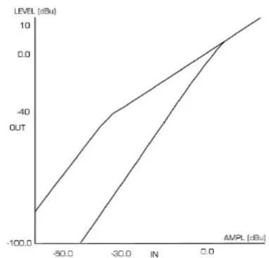
OPTICAL EXPANDER
- Threshold hold range = -20 dBfs (0 dBu) to -60 dBfs (-40 dBu).
- Expander ratio = 2:1
- Attack time = 750 μs.
- Release time = 0.25 s to 4 s.
- Noise with maximum expansion = -96 dBu measured with a 20 Hz/22 kHz bandpass filter.
- Signal to noise ratio relative to max headroom (27 dBu) = 123 dB.
- Signal to noise ratio relative to 0 dBfs (+22 dBu) = 118dB.
- 6 LED meter shows downward expansion calibrated in dB increments.
Threshold range:
line
| AMPL (dBu) | LEVEL (dBu) | | ---------- | ----------- | | -50.0 | -100.0 | | -30.0 | -40.0 | | 0.0 | 0.0 |VINTAGE HARMONICS
- Threshold range = -10 dBfs (-12 dBu) to -40 dBfs (-18 dBu).
• Compression ratio (Depth switch out) = 1:1.5
• Compression ratio (Depth switch in) = 1:3
• Mid band centre frequency = 3.5 kHz
• High band centre frequency = 20 kHz. - Band Q = 0.2
- 6 LED meters show the amount of boost at the centre frequency of the band, meter calibrated in dB increments.
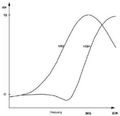
line
| Frequency | MID | HIGH | | --------- | ---- | ---- | | 0 | 0 | 0 | | 3K5 | 12 | 12 | | 2DK | 12 | 12 |OPTICAL COMPRESSOR
- Threshold hold range = -15 dBfs (7 dBu) to -40 dBfs (-18 dBu).
• Compressor ratio (Hard Ratio switch out) = 2.5:1
• Compressor ratio (Hard Ratio switch in) = 6:1 - Attack time (Slow Attack switch out) = 0.5 ms.
- Attack time (Slow Attack switch in) = 5 ms.
- Release time = 100 ms to 1 s and then auto release mode when the release knob is turned fully clockwise. Auto release creates a release time dependent upon the average level of the incoming signal.
- Noise = -94 dBu measured with a 20 Hz/22 kHz bandpass filter.
• Makeup gain = 0 to +18 dB.
Ratio:
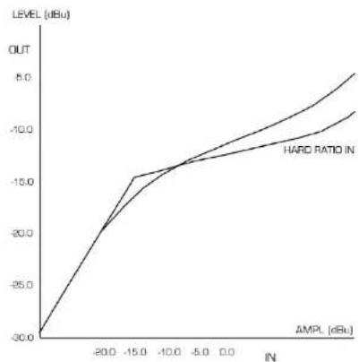
line
| IN | OUT | | ------ | ---- | | -20.0 | -30.0 | | -15.0 | -15.0 | | -10.0 | -10.0 | | -5.0 | -5.0 | | 0.0 | 0.0 |Threshold range:
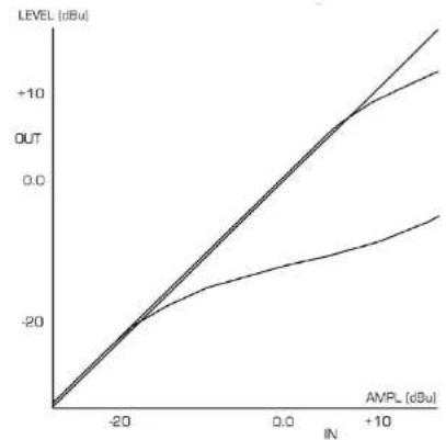
line
| IN [dBu] | LEVEL (dBu) | | -------- | ----------- | | -20 | -20 | | 0 | 0 | | +10 | +10 |TUBE SOUND
- Harmonic generation = 2nd, 3rd and 5th harmonics generated from fundamental frequency of the incoming signal relative to position of the Drive knob.
- THD with Drive knob at cool = 0.6% with a -10 dBfs (+12 dBu) 1 kHz input signal measured with a 20 Hz/22 kHz bandpass filter.
- THD with Drive knob at warm = 6% with a -10 dBfs (+12 dBu) 1 kHz input signal measured with a 20 Hz/22 kHz bandpass filter.
- The effect can be monitored visually using the drive led as follows: -
| Drive LED colour Harmonic effect | |
| Blue to Green Mostly 2nd with some 3rd. | |
| Yellow to Orange More 3rd and 5th . | |
| Orange to Red Large amounts of all harmonics above fundamental frequency. |
- Tone = 6 dB per octave roll off low pass filter.
- Tone frequency range = continuously variable from 4.5 kHz to 30 kHz measured at the 3 dB down point.
Tone Control:
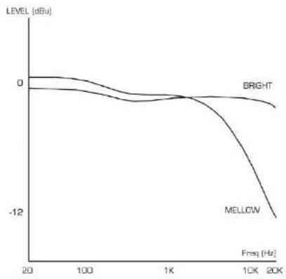
line
| Freq (Hz) | BRIGHT (dBu) | MELLOW (dBu) | | --------- | ------------ | ------------ | | 20 | 0 | 0 | | 100 | ~-2 | ~-3 | | 1K | ~-4 | ~-6 | | 10K | ~-8 | ~-12 | | 20K | ~-10 | ~-14 |VOICE OPTIMISED EQ
Breath
• EQ shape = Shelving
• Peak frequency Shift switch out = 10 kHz
• Peak frequency Shift switch in = 16 kHz
• Gain range = +/-8 dB
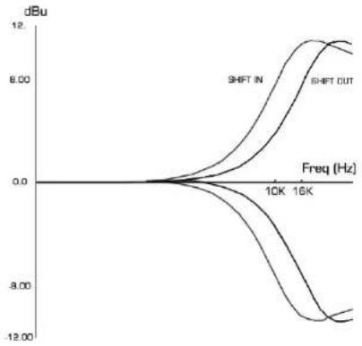
line
| Freq (Hz) | SHIFT IN (dBu) | SHIFT OUT (dBu) | | --------- | -------------- | --------------- | | 10K | 0.0 | 0.0 | | 15K | -8.00 | -12.00 |Mid
• EQ shape = Peak
• Centre frequency = 1.3 kHz
• Q in boost mode = 0.5
• Q in cut mode = 2
• Gain range = +8 to -12 dB
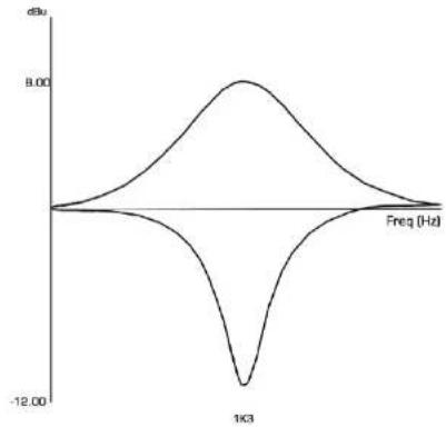
line
| Freq (Hz) | Value | | --------- | --------- | | 0 | 0.00 | | 1K3 | -12.00 | | 9.00 | 9.00 |Absence
• EQ shape = Peak
• Centre frequency = 3.9 kHz
• Q = 3.5
• Gain range = 0dB to -10 dB
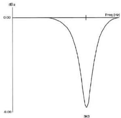
line
| Frequency (Hz) | Value (dBu) | | -------------- | ----------- | | 3K0 | -0.5 |Warmth
• EQ shape = Peak
• Centre frequency range = 120 Hz to 600 Hz
• Q in boost mode = 0.5
• Q in cut mode = 2
• Gain range = +8 to -12 dB
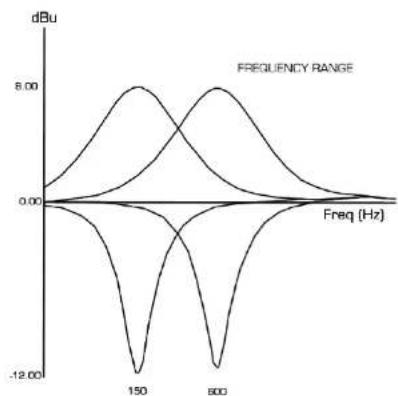
line
| Frequency (Hz) | Value (dBu) | | -------------- | ----------- | | 0.00 | 0.00 | | 150 | -12.00 | | 600 | 8.00 |DE-ESSER
- Threshold hold range = -10 dBfs (+12 dBu) to -40 dBfs (-18 dBu).
• De-esser ratio at centre frequency = 2:1
• Centre frequency range = 2.2 kHz to 10 kHz
• Q of cut = 3.5 - Attack time = 0.5 ms
- Release time = 100 ms
- Noise = -94 dBu measured with a 20 Hz/22 kHz bandpass filter.
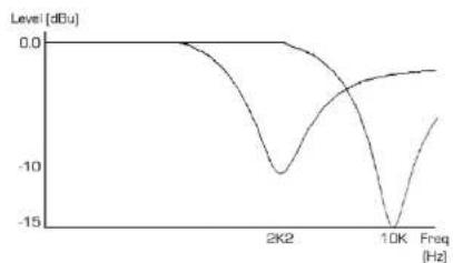
line
| Freq [Hz] | Level [dBu] | | --------- | ----------- | | 0 | 0.0 | | 2K | -10.0 | | 10K | -15.0 |OUTPUT METER
- Calibrated for 0 dBfs = +22 dBu and indicates the level after the output fader being sent to both the internal AD converter and the VoiceMaster Pro XLR output.
- O/L LED is hit when any section of the unit (including the headphone output) reaches a level greater than 0 dBfs (O/L: LED triggered at +22.4 dBu).
WEIGHT
• 5 kg
DIMENSIONS
• 482 mm (W) x 88 mm (H) x 180 mm (D)
FOCUSRITE DISTRIBUTOR LIST
Australia
Electric Factory Pty Ltd
Phone: +61 3 9480 598
Fax: +61 3 9484 6708
Email: e123620211.com.3d
Austria
TC Electronic Austria
Phone: +43 1810 1002
Fax: +43 1810 1001
Belgium
EML
Phone: +32 11 23 23 55
Fax: +32 11 23 21 72
Email: Elibenzini.de
Brazil
Pride Music
Phone: +55 11 6975-2711
Fax: +55 11 6975-2772
Email: info@pridemusic.com.br
Bulgaria
Almar Co Ltd
Phone: +359-2-511538
Fax: +359-2-795917
Email: dmar@aster.net
Canada
c/o Digitdesign (USA)
Phone: +1 650 731 6300
+1 856 FOCUSRITE
Fax: 11 650 731 6399
Email: procinfo@digidesign.com
Dino Virellai@digidesgt.com
Croatia, Slovenia, Bosnia, Macedonia and
Serbia
Music Export
Phone: +49 89 746 123 90
Fax: +49 89 746 123 92
Email: MusicExports@t-online.de
Cyprus
Techuressound
Phone: +357 2 499971
Fax: +357 2 499986
Email: technology@cylink.com.cy
Czech Republic
Audiopolis Studio Systems
Phone: +120 2 4148 3501
Fax: +120 2 41 18 3505
Email: sales@audiopolis.cz
Mediaport
Phone: +420 2 7173 5610
Fax: +420 2 7273 4897
Email: info@mediaport.cz
Denmark
New Musik AG
Phone: -15 R6 190879
Fax +45 86 195199
Digital Media Technology
Phone: +852 2721 0343
Tax +852 2365 6883
Email: danbk@dmtpro.com
Hungary
Absolute
Phone: -361 252 0196
Fax: +361 341 0272
Email: ad@absolute.in
Iceland
Exton
Phone: -354 351 25
Fax: +354 562 6490
Email: cxton@exton.is
India
R & S Electromes
Phone: +91 22 636 9147
Fax: +91 22 636 9691
Email: randsan@vsl.com
Indonesia
PT Santika Multi Jaya
Phone: +62 21 650 6040
Fax +62 21 050 880
Email: yufo@undosat.net.id
Paradi
Phone: +62 21 831 8388
Pax +62 21 8370 3473
Email: Paradi@cbu.net.Id
Israel
Sociennes
Phone: 1972 3 570 5223
Fax: +972 3 619 9297
Email: sonlines@inter.net.d
Italy
Grisby Music Professional
Phone: +39 0 71 7108471
Fax: +39 071 7108477
Email: grisbymusic@rin.ie
Japan
All Access Inc
Phone: +81 52 443 5557
PAX +81 52 +43 7738
Email: info@allaccess.co.jp
R. O. Maldives
Island Acoustics
Phone: 1950 32 0052
Fax: +960 31 8624
Email: blnusic@dluveline.net.mv
Mexico
Email: veritaspa@gvarinter.com.mx
Netherlands
Total Audio BV
Phone: +31 20-4176447
Fax: +31 20 4476454
Email: info@total-andio.nl
New Zealand
Protel
Phone: +64 4 801 9494
Fax +64 4 384 2112
Email: rob@wm.protel.co.nz
Norway
Lydrommet
Phone: +47 22 80 94 50
Fax: +47 22 80 94 (6)
Email: admin@lydromnet.no
Poland
Music Info
Phone: -18 12 267 2480
Fax: -48 12 267 2224
Email: info@nubc.com.pl
Portugal
Caius Tecnologias
Phone: -35 122 208 6006
Fax: -35 122 208 5969
Email: cnbs@nalt.telesec.pl
Romania
A.F. Marcoter (Bucharest)
Phone: -40 1 337 1254
Fix: -4013371254
Email: mha@ceo.ca@exml.ro
Russia, Baltics, Ukraine
ATT Trade
Phone: -7 095 956 1105 Fax: 7 095 056 6882
136-7105 956 5882 Email:info.broad@
Email: xipix-ramn@zq.com
Singapore/Malaysia
Team: 108
Phone: -65 748 9333
Fax: -65 747 7273
Email: 108@cm108.com.sg
Slovakia
Centron
Phone: -421 264 780967
Fax: 421 264 780042
Email: centron@bu.profinet.sk
South Africa
Powerhouse Electronics
Phone: -27 11 44 206
Tax: -27 11 444 8416
Email: eirle@powerhouse-sa.com
South Korea
Best Logic Sound Co.
Phone: -82 2 515 7385
Fax: -82 2 516 7385
Email: lscoldi@intel.net
Spain
Media Sys S.L
Phone: -34 93 426 6500
Fax: -34 93 424 7337
Email: mediasys@interplanet.cs
Sri Lanka
LHi Centre Ltd
Phone: -941580442
Fax: -941 503174
Email: lini@eureku.lk
Sweden
Polysonic ab
Phone: +46 31 7069050
Fax-45317069110
Email: polysone@polysone.com
Switzerland
Bleuel Electronic ag
Phone: +41 1 751 7550
Fax: +41 1 751 7500
E-mail: Biedel-electrosvissoline.cri
Taiwan
Digital Media Technology (DMT) (Taiwan)
Liu
Phone: +880 2 25164318
Fax: 1880-2-25159861 Fax: http://dxtna.com
E-mail: http://iripid.com
Thailand
KFC
Phone: +66 2 222 8613/4 Fax: +66 2 225 1471
Fax: kas@loxiao.c
-
- 10:31
United Arab Emirates
NMR Electronics Ent
Phone: +971 4626683
PAX: -971 620682 Email: prak@cenix
Elae. Edoqctnlos de lae
United Kingdom & Ireland
Focusrite Audio Engineering Ltd
Phone: +44 (0) 1494 462246
Fax: +44 (0) 1494 459920
Email: sales@locusrite.com
USA
Digidesign
Phone: +1 630 751 Baidu
+1866 FOCUSRITE
PAX: +1 659 731 K19
Email: procinfo@xdigdesign.com
Dinfo_Virella@digidesign.com
Venezuela
Avtom CA
Phone: +58 212 237 7762
Fax: -58 212 237 8275
Email: jmcudez@avcom.com vc
Vietnam
Vistar
Phone: +84 1 824 3058
Fax: +84 1 825 0099
Email: Han@huaicredarch.org.MH
Other territories not listed:
Please contact Focusrise United Kingdom.
NOTES
NOTES