CN04 200 MIS F - Heating Tesy - Free user manual and instructions
Find the device manual for free CN04 200 MIS F Tesy in PDF.

| Product type | Electric convector |
| Brand | Tesy |
| Model | CN04 200 MIS F |
| Rated power | 2000 W |
| Power supply | 230 V ~ 50 Hz |
| Protection rating | IP24 |
| Recommended heating area | 16 - 24 m² |
| Recommended heating volume | 40 - 60 m³ |
| Standard ceiling height | 2.5 m |
| Control | Mechanical (On/Off button and adjustment knob) |
| Operating modes | Frost protection (standby), Eco (1-2), Comfort (3-5), Forced operation (6) |
| Thermostat | Mechanical, adjustable from 1 to 6 |
| Safety | Overheat protection and anti-tilt switch |
| Installation | On floor feet (wall mounting not intended) |
| Approximate dimensions (W x H x D) | 80 x 45 x 10 cm |
| Approximate weight | 5.5 kg |
| Power cable length | Approximately 1.5 m |
| Housing material | Steel and plastic |
| Color | White |
| Use | Indoor only |
| Cleaning | Vacuum cleaner or damp cloth; do not immerse |
| Storage | In original packaging, in a dry and dark place |
Frequently Asked Questions - CN04 200 MIS F Tesy
User questions about CN04 200 MIS F Tesy
0 question about this device. Answer the ones you know or ask your own.
Ask a new question about this device
Download the instructions for your Heating in PDF format for free! Find your manual CN04 200 MIS F - Tesy and take your electronic device back in hand. On this page are published all the documents necessary for the use of your device. CN04 200 MIS F by Tesy.
USER MANUAL CN04 200 MIS F Tesy
natural_image
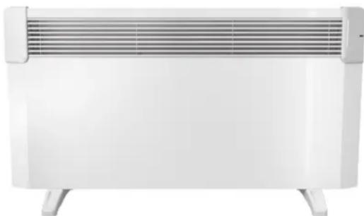
Abstract gray arrow shape pointing right, no text or symbols presentEN ELECTRIC PANEL HEATER 2-5 Operation and Storage Manual of Panel Heater
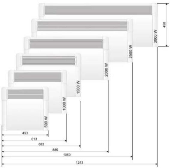
500/1000/1500/2000/2500/3000W
natural_image
White electric heater with horizontal ventilation grille and side legs (no text or symbols visible)EN This product is only suitable for well insulated spaces or occasional use. | BG Tosi produkt e подходящ само за надеждно изолирани помещения или нередовна употреба. | RO Acest produs este adecvat numai pentru spațiile bine izolate sau pentru utilizarea ocazională. | ES Este producto está indicado únicamente en lugares abrigados o para una utilización puntual. | PT Este produto é adeguado apenas para espaços bem isolados espaços ou utilização ocasional. | DE Dieses Produkt ist nur für gut isolierte Raume oder für den gelegentlichen Gebrauch geeignet. | IT II presente prodotto è adatto solo a ambienti correttamente isolati o ad un uso occasionale. | FR Ce produit ne peut être utilisé que dans des locaux bien isolés ou de manière occasionnelle. | DK Dette produkt er kun egnet til godt isolerede rum eller lejlighedsvis brug. | GR To προϊόν ειναι καταλληλο μόνο για χοήση σε καλά μονωμένους χώρους ή περιστασιακά. | HU A termék kizárólag jól szigetelt helyiségek fütéséré vagy alkalmankénti használatra alkalmas. | PL Ten produkt jest odpowiedni tylko do sporadycznego użytku lub do stosowania w dobrže izolowanych pomieszczeniach. | CZ Tento výrobek je vhodný pouze pro dobře izolované prostory nebo občasné používání. | SK Tento výrobok je určený iba do dobre izolovaných priestorov alebo na priležitostne použitie. | HR Ovaj je proizvod prikladan samo za dobro izolirane prostore ili povremenu uporabu. | SL Ta izdelek je primeren le za uporabo y dobro izoliranih prostorih ali za priložnostno uporabo. | LT Sis gaminys tinkamas naudotí tik gerai izoliuotose patalpose arba tik retkarciais. | LV Sis razojums ir derigs tikai izmantosanai telpās ar labu izolaciju vai néregulárai izmantosanai. | EE See toode sobib kasutamiseks üksnes hästi isoleeritud kohtades ja üksikjuhtudel. | NL Dit product is uitsluitend geschikt vóor goed geisoleerde plaatsen of voor incidenteel gebruik.
IMPORTANT SAFETY MEASURES AND INSTRUCTIONS:

WARNING!
- Please read this manual before operating the appliance and keep it at a safe place for future reference. In case the appliance is obtained by a new owner, it should be transferred together with its manual.
- CAUTION: Children under 3 years of age should be kept away from the appliance unless they are under constant supervision.
Children from 3 to 8 years of age are allowed to operate the on/off button ONLY, provided that the appliance is installed and ready for operation and such children have been supervised and instructed in safe operation of the appliance and they understand all related risks.
Children from 3 to 8 years of age MUST NOT: connect the plug to power sockets, make adjustments, clean it or carry out user maintenance operations.
This appliance can be used by children older than 8 years of age and by people with reduced physical, sensor and mental capabilities, as well as by people with insufficient experience and knowledge provided they are supervised or instructed in safe operation of the appliance and understand the related risks. Children should not be allowed to play with the appliance. Cleaning and user maintenance operations must not be carried out by children without supervision.
- CAUTION: Some of the appliance parts may get very hot during operation and thus cause burns to users. In case there are children and vulnerable people in the room, special attention should be paid.
- WARNING: Do not cover the appliance in order to prevent overheating!

• The appliance must not be placed right under a socket box!
- If the supply cord is damaged, it must be replaced by the manufacturer, its service agent or similarly qualified persons in order to avoid a hazard.
- Before connecting the appliance to the mains, check if the voltage indicated on its technical plate corresponds to the voltage of the electricity, supplied to your house.
- This appliance shall be used only for the purpose it has been designed and intended for, i.e. heating of domestic premises. The appliance is not intended for commercial/industrial application. Every other use is to be considered improper, and therefore dangerous. The manufacturer doesn't bear responsibility for damages arising from improper and irrational use. Non-adherence to these instructions would render the warranty invalid!
- Do not leave your home while the heater is operating: make sure that the power switch is in OFF position (panel heaters with mechanical control).
- Keep inflammable objects, such as furniture, pillows, bedding, paper, clothes, curtains etc. at a safe distance of at least 100 cm away from the panel heater.
- Do not operate the appliance in areas of use or storage of combustible substances. Do not operate the appliance in areas of combustible media (for example in close proximity to inflammable gases or aerosols) – there is great risk of explosion and fire!
- Do not insert and do not allow foreign objects to enter the ventilation openings (inlet and outlet) because this will cause electric shock, fire or will damage the appliance.
- The appliance is not suitable for animal breeding. The panel heater is intended for domestic/indoor operation only.
- When positioning the appliance, do not cover the safety grilles; do not hamper the incoming and outgoing air flow. All objects must be at a safe distance of at least 1 meter away from the appliance front and sides.
- The most common reason for overheating is dust and fluff deposits in the appliance. Clean the ventilation openings on a regular basis with a vacuum cleaner, but before that it is very important to disconnect the heater from the mains.
- Never touch the appliance with wet or moist hands – there is risk for your life!
- The power socket should be accessible all the time in order to disconnect the power plug when needed as fast as possible! Never pull the power cord or the appliance itself in order to disconnect it from the mains.
- PAY ATTENTION! Outgoing air gets heated during appliance operation (up to more than 100°C).
- If you decide to stop using an appliance of this kind, it is recommended to make it unusable by cutting its power cord after you have disconnected it from the mains. It is advisable all possible risks related to the appliance to be secured,
especially in relation to children that may play with out-of-use appliances.
- Warning: Do not use this appliance with a programmer, counter or any other mechanism which could automatically turn on the heater – if the appliance is covered or positioned incorrectly there is a risk of fire.
- Position the power cord in such a way that it does not obstruct the free movement of people and cannot be stepped on! Use only approved extension cords, which are suitable for this appliance, i.e. they have a compliance sign!
- Never move the appliance by pulling its power cord; do not use the power cord for carrying other objects!
- Do not bend the power cord and do not pull it against sharp edges; do not place the power cord on hot surfaces or open fire!
PACKING
• After unpacking the appliance, check if its contents are intact and if it has not been damaged during transportation! In case a damage or incomplete delivery is found, contact your authorized retailer!
- Do not dispose of the original packing box! It could be used for storage and transportation purposes in order to avoid damages during transportation!
- Disposal of packing material should be done in the appropriate way! Children must be prevented from playing with polyethylene bags!
OPERATION AND INSTALLATION OF FEET SET
- This panel heater is designed to be used indoors.
In accordance with Regulation EU 2015/1188 implementing Directive 2009/125/EC this electric heating appliance is not intended for wall installation!

Important: In premises bigger than 45 m^3 , it is recommended to use a combination of 2 or more panel heaters.
- Do not position the panel heater under a power socket or electricity connection box.
-
DO NOT install/operate the panel heater:
-
in places where a draught is present, which could influence the control settings;
- right under a power socket;
- in "Volume 1" for bathrooms;
-
in "Volume 2" if the control board can be reached by a person who is in a shower or in a bathtub;
-
Before starting the set installation check if the panel heater is disconnected from the power socket!
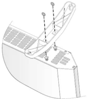
- The feet are to be installed at side of the air inlets – it is correct them to be installed at the two sides ends of the panel heater in a symmetrical on the appointed place (see picture below). For installation purposes – all panel heaters have got 2 openings for every foot.
natural_image
Technical line drawing of a mechanical component with no visible text or symbols- Mount the first foot on the appointed place. Then you should screw the two securing screws. The screw goes through the plastic foot and gets screwed into plastic nut based on panel heater. You should repeat the same operation for the second foot.
- The joint is secure in case the panel heater stands horizontally on the floor after its feet installation has been completed. Do not use the power cord as a pulling rope in order to move the panel heater; any movement of the panel heater should be done when it is cold.
- Position the panel heater with installed feet on the floor and before
connecting it to the power socket check if all instructions from the very beginning of this manual have been followed correctly (Important instructions and safety measures). The correct position is – the control panel should be at the top of the appliance and the feet – on the floor!
BATHROOM OPERATION
• The panel heater must be installed in accordance with the normal trade practices and in compliance with the national legislation (EU electricity directives and regulations concerning special installations and places of operation including bathrooms, shower cabins HD60364-7-701(IEC 60364-7-701:2006)).
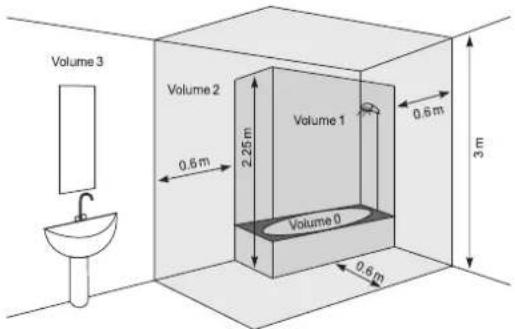
- In case this panel heater is to be used in a bathroom or other similar room, the following installation requirements must be observed: the panel heater is with IP24 protection (water drops protection). Hence it can be installed in "Volume 2" (see the diagram below) in order to avoid the risk of the control board (power switch and thermo regulator) being reached by a person who is in a shower or a bathtub. The minimum distance between the appliance and a water source should be not less than 1 meter! If you do not feel sure about the installation of this panel heater in a bathroom, we recommend you to consult a professional electrician.

Note: If the above-mentioned instructions cannot be implemented, it is recommended to install the appliance in "VOLUME 3".
- In wet premises the power source must be installed at a height of at least 25 cm above the floor (bathrooms and kitchens).
- The installation must be equipped with a safety fuse, and the distance between the fuse contacts in disconnected condition should be at least 3 mm.
Thank you for choosing CN04 panel heater. This is a product providing heating in winter depending on the consumers' needs for comfortable room temperature. If operated and taken care of properly in accordance with these instructions, the appliance will provide you with many years of useful operation.
OPERATION INSTRUCTIONS
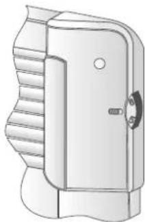
MECHANICAL CONTROL
Operation modes
Turn the panel heater on by pushing the switch in position "I" (turned-on) then turn the regulator to the desired level (1 to 6) as you take into account the following relation between the power levels:
* - anti-freezing mode/ enabled when room temperature falls below 7°C
1 / 2 – economy mode/ it maintains low room temperature/ this mode is recommended to be used at night and when there are no people present in the room. This mode permits to maintain the set room temperature while saving energy.
3 / 4 / 5 - comfort mode/ it maintains moderate room temperature/ this mode is recommended to be used to maintain relatively high comfortable room temperature during the day.
6 - maximum power mode / it maintains HIGH room temperature/ this mode is recommended to be used when you need maximum high room temperature
natural_image
Technical line drawing of a mechanical device with ribbed top and handle (no text or symbols)
Important: Thermo Regulator digits do not correspond to certain room temperature levels, but they can be used by users to memorize the relation
between room temperature and the thermo regulator settings. For fine adjustment
you can use thermometer- as you follow the principle of room temperature measurement for a few hours (it is set according to the size of the heated premises).
When the room temperature is lower than the temperature that you have set by the thermo regulator, the panel heater starts its operation and will operate until the room temperature reaches the set temperature level of the unit. When the room temperature is higher than the adjusted temperature of the appliance, the panel heater will automatically go into "Stand by" mode.
PROTECTION
- The appliance is equipped with a safety thermo turn-off device, which automatically turns the heater off in cases of extreme temperature of the panel heater /i.e. overheating of the appliance/.
- The safety thermo turn-off device will automatically restore the heater operation when the temperature of the appliance falls below the permissible ultimate values.
TIP-OVER PROTECTION
This heater is protected with a safety switch that turns off the appliance automatically when the heater falls over, or is at an excessive angle from the horizontal. This helps prevent accidents, and the heater will back to last set mode when it is put back upright.
CLEANING
- It is compulsory first to turn off the appliance through its power switch and to disconnect it from the power socket. Before starting the cleaning session you should wait until the panel heater cools down in a disconnected state.
- Clean the heater body with damp cloth, vacuum cleaner or a brush.
- Never immerse the appliance into water – there is danger for your life from electric shock!
- Never use gasoline, thinner or hard abrasive products to clean the appliance, because they will damage the appliance coating.
STORAGE
- Before putting the panel heater away let it cool down after you have disconnected it from the power socket
- Use the appliance original packing to store it, if the panel heater will not be in use for a long period of time. By storing the product in its original packing you protect it from excessive dirt and dust accumulation.
- Never put a hot panel heater in its packing!
- It is necessary the product to be stored at a dry and dark place, protected from direct sun light.
- It is explicitly forbidden to store the panel heater in damp and wet premises.
MAINTENANCE OPERATIONS OF THE APPLIANCE
- In case of appliance malfunction, please contact the authorized service center closest to your location. /service centers are indicated in appliance warranty documents/.
- Important: In case of a claim and/or violation of your consumer rights, please contact the supplier of this appliance at the indicated locations or via the Internet page of the company: www.tesy.com
DIMENSIONS OF HEATED VOLUME AND HEATED AREA OF A ROOM / APPLIANCE MODELS
| Model Heated volume Heated area | |
| CN 04 050 MIS F - 500W 10* - 15 m ^3 | 4* - 6 m^2 |
| CN 04 100 MIS F - 1000W 20* - 30 m ^3 | 8* - 12 m^2 |
| CN 04 150 MIS F - 1500W 30* - 45 m ^3 | 12* - 18 m^2 |
| CN 04 200 MIS F - 2000W 40* - 60 m ^3 | 16* - 24 m^2 |
| CN 04 250 MIS F - 2500W 50* - 70 m ^3 | 20* - 28 m^2 |
| CN 04 300 MIS F - 3000W 60* - 80 m ^3 | 24* - 30 m^2 |
* Minimum guaranteed heated volume (area) for heating at an average capacity of heat transmission factor =0.5 W/(m^2K) for a heated room. Higher values of heated volume (area) can be achieved at an average value of =0.35 W/(m^2K) . Standard height of heated rooms – 2.5 meters.
other
| Component | Dimension (W) | | :--- | :--- | | Top Layer | 3000 | | Middle Layer | 2500 | | Bottom Layer | 1500 | | Left Layer | 1000 | | Right Layer | 450 | | Bottom Layer | 683 | | Middle Layer | 493 | | Top Layer | 1243 | | Middle Layer | 885 | | Bottom Layer | 1060 | | Left Layer | 613 |
Environment protection instructions
Obsolete electric appliances contain valuable materials and consequently they should not be treated as domestic waste! We ask for your cooperation and your active contribution to protect the resources and the environment. Please submit your out-of-use appliances to the organized buy-back stations (if there are such).
TABLE 2: INFORMATION REQUIREMENTS FOR ELECTRIC LOCAL SPACE HEATERS
Model identifier(s): 1.CN04 050 MIS F; 2.CN04 100 MIS F; 3.CN04 150 MIS F; 4.CN04 200 MIS F; 5.CN04 250 MIS F; 6.CN04 300 MIS F 230V\~50Hz
| Item | Symbol | Value 1. | Value 2. | Value 3. | Value 4. | Value 5. | Value 6. | Unit | Item | Unit |
| Heat output Type of heat input for electric storage local space heaters only (select one) | ||||||||||
| Nominal heat output P | nom | 0.50 | 1.00 | 1.50 | 2.00 | 2.50 | 3.00 | kW | Manual heat charge control, with integrated thermostat | [no] |
| Minimum heat output (indicative) P | min | 0.00 | 0.00 | 0.00 | 0.00 | 0.00 | 0.00 | kW | Manual heat charge control, with room and/or outdoor temperature feedback | [no] |
| Maximum continuous heat output (indicative) | P_max,C | 0.50 | 1.00 | 1.50 | 2.00 | 2.50 | 3.00 | kW | Electric heat charge control, with room and/or outdoor temperature feedback heat charge control, with integrated thermostat | [no] |
| Auxiliary electricity consumption Fan assisted heat output [no] | ||||||||||
| At nominal heat output el | max | 0.44 | 0.91 | 1.42 | 1.89 | 2.41 | 2.87 | kW | Type of heat output/room temperature control (select one) | - |
| At minimum heat output el | min | 0.00 | 0.00 | 0.00 | 0.00 | 0.00 | 0.00 | kW | Single stage heat output and no room temperature control | [no] |
| In standby mode | el SB | 0.00 | 0.00 | 0.00 | 0.00 | 0.00 | 0.00 | kW | Two or more manual stages, no room temperature control | [no] |
| With mechanic thermostat room temperature control | [yes] | |||||||||
| With electronic room temperature control | [no] | |||||||||
| With electronic room temperature control plus day timer | [no] | |||||||||
| With electronic room temperature control plus week timer | [no] | |||||||||
| Other control options (multiple selections possible) | ||||||||||
| Room temperature control, with presence detection | [no] | |||||||||
| Room temperature control, with open window detection | [no] | |||||||||
| With distance control option | [no] | |||||||||
| With adaptive start control | [no] | |||||||||
| With working time limitation | [no] | |||||||||
| With black bulb sensor | [no] | |||||||||
TESY Ltd
48 Madara Blvd,
Shumen, 9700,
Bulgaria
TROUBLESHOOTING
Prior to contacting the Customer Service Center, please check the items in the table below.
EN
| PROBLEM CAUSE SOLUTION | ||
| The appliance doesn't work No power supply from the grid. Be sure that the product is plugged in and that the electrical outlet is working. | Plug into the power outlet and check position of the ON/OFF switch. | |
| Room does not get warm enough although the appliance is hot | Appliance overheating. High limit safety cut-out limits heating output. | Eliminate the cause (cover, dirt or obstructions at the air inlet or outlet).Observe minimum clearances according to mounting instructions. |
| The heat demand of the room is higher than the appliance output. | Remove heat losses (Close windows and doors. Avoid constant venting.) | |
| Check if the power of your device is adapted to the size of your room. | Recommended an average of 100 W/m2 for a ceiling height of 2,50m or 30W/m3 | |
| Dirty marks appear on the wall around the device | The dirty marks come as a result of air contamination. Make sure that some fresh air enters the room regularly, especially if it is used for smoking. | |
| Sounds/Noises Emitting faint noises during the heating process and shortly after the set temperature is reached, is not something unusual. | Such effect is in result of the natural materials expansions during the rapid temperature increase and following cooling of the metals used for the product manufacturing. | |
| Yellowish stains on the grid Such stains could be in result of covering the product with wet clothes. | Do not cover the product! Such actions are not allowed, because they block the air convection and will damage the product irreparably, leading to serious risk for your health and properties. | |
natural_image
Technical line drawing of a mechanical component with labeled parts (no text or symbols)natural_image
Technical line drawing of a mechanical component with ribbed texture and a handle (no text or symbols)natural_image
Technical line drawing of a mechanical component with mounting holes and internal structure (no text or symbols)natural_image
Technical line drawing of a mechanical device with ribbed and mounting features (no text or symbols)other
| Section | Width (W) | | ------- | --------- | | Top Section | 493 | | Middle Section | 613 | | Bottom Section | 683 | | Bottom Section | 885 | | Middle Section | 1000 | | Middle Section | 1500 | | Middle Section | 2000 | | Middle Section | 2500 | | Middle Section | 3000 | | Bottom Section | 1243 | The chart displays a single vertical bar for each section, with the top section being the longest and the bottom section the shortest. The width values are explicitly labeled on the bars.
natural_image
Technical line drawing of a mechanical component with mounting holes and a curved base (no text or symbols)natural_image
Technical line drawing of a mechanical component with no visible text or symbolsnatural_image
Technical line drawing of a mechanical component with ribbed texture and a handle (no text or symbols)natural_image
Technical line drawing of a mechanical component with mounting holes and structural supports (no text or symbols)- Ako ovaj konvektor će se koristiti u kupaonici ili u drugim sličnim prostorima moraju biti ispunjeni sljedeći zahtjevi za instalaciju: konvektor je sa zaštitom IP24 (zaštita od prskanja vode). Zbog ove činjenice se mora ugraditi u prostoru 2 (volume2) (vidi sliku dolje) kako bi se izbjegla mogućnost ova upravljačka ploča (prekidač i termostat) konvektora da se može dostigne od strane čovjeka koji je pod tušem ili u kadi. Minimalna udaljenost od aparata do izvora vode ne smije biti manji od 1 metra! Ako niste sigurni o instaliranju ovog konvektora u prostoru za kupaonicu, mi preporučujemo da se konzultirate stručnu osobu.

Napomena: Ako se ne mogu zadovoljiti gore navedeni uvjeti, preporuča se instalacija da bude izvedena u prostoru 3 (Volume 3).
- U vlažnim prostorijama (kupaonice i kuhinje) izvor energije mora biti montiran na visini od najmanje 25 cm od poda.
- Instalacija mora biti opremljena automatskim osiguračem pri čemu udaljenost između kontakata kada je isključen, mora biti najmanje 3 mm.
Zahvaljujemo da ste odabirali konvektor CN04. Ovo je uređaj koji nudi grijanje u zimi koliko je potrebno kako bi se postigla udobna toplina u zagrijanoj prostoriji. Uz pravilnu uporabu i njegu kao što je opisano u ovim uputama, uređaj će pružiti mnogo godina korisnog rada.
UPUTE ZA UPORABU
MEHANIČKO UPRAVLJANJE
Režimi rada
natural_image
Technical line drawing of a mechanical component with ribbed texture and a handle (no text or symbols)3 / 4 / 5 – udoban režim / za održavanje umjerene temperature u prostoriji / ovaj način se preporučuje da se koristi za zadržavanje relativno visoke udobne dnevne temperature u prostoriji.
6 – maksimalni režim / za održavanje VISOKE temperature u prostoriji / ovaj način se preporučuje kada je vam potrebna maksimalno visoka temperatura u prostoriji

other
| Dimension | Value | | :--- | :--- | | Width (mm) | 493 | | Height (m) | 613 | | Base Width (m) | 683 | | Base Width (cm) | 885 | | Base Width (cm) | 1060 | | Base Width (cm) | 1243 | | Base Width (cm) | 1000 | | Base Width (cm) | 1500 | | Base Width (cm) | 2000 | | Base Width (cm) | 2500 | | Base Width (cm) | 3000 | | Base Width (cm) | 450 |
natural_image
Technical line drawing of a mechanical component with labeled parts (no text or symbols)natural_image
Technical line drawing of a mechanical device with ribbed top and handle (no text or symbols)natural_image
Technical line drawing of a mechanical component with mounting holes and structural supports (no text or symbols)natural_image
Technical line drawing of a mechanical device with ribbed top and handle (no text or symbols)natural_image
Technical line drawing of a mechanical component with no visible text or symbolsnatural_image
Technical line drawing of a mechanical device with ribbed top and handle (no text or symbols)other
| Dimension | Value | | :--- | :--- | | Width (inches) | 493 | | Height (inches) | 613 | | Base Width (inches) | 683 | | Base Height (inches) | 885 | | Base Width (inches) | 1060 | | Base Height (inches) | 1243 | | Base Width (inches) | 1000 | | Base Height (inches) | 1500 | | Base Width (inches) | 2000 | | Base Height (inches) | 2500 | | Base Width (inches) | 3000 | | Base Height (inches) | 450 |TABULKA 2: POŽIADAVKY NA INFORMÁCIE PRE ELEKTRICKÉ LOKÁLNE OHRIEVAČE PRIESTORU
Identifikačný(-é) kód (-y) modelu: 1.CN04 050 MIS F; 2.CN04 100 MIS F; 3.CN04 150 MIS F; 4.CN04 200 MIS F; 5.CN04 250 MIS F; 6.CN04 300 MIS F 230V\~ 50Hz
natural_image
Technical line drawing of a mechanical component with mounting holes and internal structure (no text or symbols)natural_image
Technical line drawing of a mechanical device with ribbed top and handle (no text or symbols)other
| Section | Height (W) | | ------- | ---------- | | Top | 493 | | Middle | 613 | | Bottom | 683 | | Middle | 885 | | Bottom | 1060 | | Top | 1243 | | Middle | 1000 | | Bottom | 500 | | Middle | 1500 | | Bottom | 2000 | | Top | 2500 | | Middle | 3000 | | Bottom | 450 |PREGLEDNICA 2: ZAHTEVE GLEDE INFORMACIJ ZA LOKALNE ELEKTRIČNE GRELNIKE PROSTOROV
Identifikacijska oznaka modela(-ov): 1.CN04 050 MIS F; 2.CN04 100 MIS F; 3.CN04 150 MIS F; 4.CN04 200 MIS F; 5.CN04 250 MIS F; 6.CN04 300 MIS F 230V\~50Hz
natural_image
Technical line drawing of a mechanical component with mounting holes and internal structure (no text or symbols)natural_image
Technical line drawing of a door handle with ribbed top and handle (no text or symbols)natural_image
Technical line drawing of a mechanical component with labeled parts (no text or symbols)natural_image
Technical line drawing of a mechanical device with ribbed top and side panel (no text or symbols)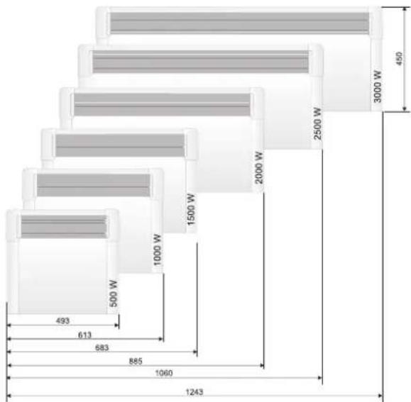
other
| Section | Height (W) | | ------- | ---------- | | Top | 493 | | Middle | 613 | | Bottom | 683 | | Middle | 885 | | Bottom | 1060 | | Top | 1243 | | Middle | 1000 | | Bottom | 500 | | Middle | 1500 | | Bottom | 2000 | | Top | 2500 | | Middle | 3000 | | Bottom | 450 |TABULKA 2: POŽADAVKY NA INFORMACE TÝKAJÍCÍ SE ELEKTRICKÝCH LOKÁLNÍCH TOPIDEL
Identifikační značka (značky) modelu: 1.CN04 050 MIS F; 2.CN04 100 MIS F; 3.CN04 150 MIS F; 4.CN04 200 MIS F; 5.CN04 250 MIS F; 6.CN04 300 MIS F 230V\~ 50Hz
natural_image
Technical line drawing of a mechanical component with mounting holes and a curved base (no text or symbols)natural_image
Technical line drawing of a mechanical device with ribbed top and handle (no text or symbols)natural_image
Technical line drawing of a mechanical component with mounting holes and a curved base (no text or symbols)natural_image
Technical line drawing of a mechanical device with ribbed top and handle (no text or symbols)other
| Dimension | Value | |---|---| | Top Section | 3000 W | | Middle Section | 2500 W | | Bottom Section | 1500 W | | Left Section | 1000 W | | Right Section | 885 W | | Bottom Section | 663 W | | Middle Section | 613 W | | Top Section | 493 W | | Middle Section | 1243 W | | Bottom Section | 1060 W | The chart displays a schematic layout of a multi-level structure with labeled dimensions in watts.
natural_image
Technical line drawing of a mechanical component with no visible text or symbolsnatural_image
Technical line drawing of a mechanical door or switch component (no text or symbols)other
| Dimension | Value | | :--- | :--- | | Width (mm) | 493 | | Height (m) | 613 | | Base Width (m) | 683 | | Base Height (m) | 885 | | Base Width (cm) | 1060 | | Base Height (cm) | 1243 | | Base Width (cm) | 1000 | | Base Height (cm) | 1500 | | Base Width (cm) | 2000 | | Base Height (cm) | 2500 | | Base Width (cm) | 3000 | | Base Height (cm) | 450 |
natural_image
Technical line drawing of a mechanical component with mounting holes and internal structure (no text or symbols)natural_image
Technical illustration of a mechanical device with ribbed and mounting features (no text or symbols)PROBLEMA CAUSA SOLUÇÃO
natural_image
Technical line drawing of a mechanical component with mounting holes and a curved base (no text or symbols)natural_image
Technical line drawing of a mechanical device with ribbed top and handle (no text or symbols)PROBLEMA CAUSA SOLUZIONE
natural_image
Technical line drawing of a mechanical component with labeled parts (no text or symbols)natural_image
Technical line drawing of a mechanical component with ribbed and mounting features (no text or symbols)natural_image
Technical line drawing of a mechanical component with mounting holes and structural supports (no text or symbols)natural_image
Technical line drawing of a mechanical component with ribbed and curved surfaces (no text or symbols)PROBLÈME CAUSE SOLUTION
natural_image
Technical line drawing of a mechanical component with mounting holes and structural supports (no text or symbols)natural_image
Technical line drawing of a mechanical device with ribbed internal structure and handle (no text or symbols)SIKRING
APPARATETS DIMENSIONER, OPVARMET VOLUMEN OG AREAL
| Model Opvarmet volumen Opvarmet areal | |
| CN 04 050 MIS F - 500W 10* - 15 m3 | 4* - 6 m2 |
| CN 04 100 MIS F - 1000W 20* - 30 m3 | 8* - 12 m2 |
| CN 04 150 MIS F - 1500W 30* - 45 m3 | 12* - 18 m2 |
| CN 04 200 MIS F - 2000W 40* - 60 m3 | 16* - 24 m2 |
| CN 04 250 MIS F - 2500W 50* - 70 m3 | 20* - 28 m2 |
| CN 04 300 MIS F - 3000W 60* - 80 m3 | 24* - 30 m2 |
natural_image
Technical line drawing of a mechanical component with mounting holes and a curved base (no text or symbols)natural_image
Technical line drawing of a mechanical device with ribbed top and handle (no text or symbols)natural_image
Technical line drawing of a mechanical component with mounting holes and internal structure (no text or symbols)natural_image
Illustration of a door handle with a handle and ventilation slots (no text or symbols)other
| Dimension | Value | |---|---| | Top Section | 3000 W | | Middle Section | 2500 W | | Bottom Section | 1500 W | | Left Section | 1000 W | | Right Section | 493 | | Bottom Section (Width) | 613 | | Bottom Section (Width) | 583 | | Bottom Section (Width) | 585 | | Top Section (Width) | 1243 | The chart displays a single horizontal bar for each section, with numerical values indicating their respective dimensions. The width of the bar is labeled as 493. The height of the bar is labeled as 1243.2. TABULA INFORMĂCIJAS PRASĪBAS ELEKTRISKAJIEM LOKĀLAJIEM TELPU SILDĪTĀJIEM
Modela identifikators(-i): 1.CN04 050 MIS F; 2.CN04 100 MIS F; 3.CN04 150 MIS F; 4.CN04 200 MIS F; 5.CN04 250 MIS F; 6.CN04 300 MIS F 230V\~50Hz
OLULISED PREVENTIIVSED MEETMED JA OHUTUSJUHENDID:

TÄHELEPANU:
natural_image
Technical line drawing of a mechanical component with mounting holes and internal structure (no text or symbols)natural_image
Technical line drawing of a mechanical component with ribbed texture and a handle (no text or symbols)KAITSE
natural_image
Technical line drawing of a mechanical component with no visible text or symbolsnatural_image
Technical illustration of a mechanical lock or latch component (no text or symbols)other
| Section | Value | | ------- | ----- | | Top Section | 3000 W | | Middle Section | 2500 W | | Bottom Section | 1243 | | Left Section | 500 W | | Right Section | 450 | | Bottom Section | 683 | | Middle Section | 613 | | Top Section (Left) | 493 | | Middle Section (Right) | 1060 | | Bottom Section (Left) | 885 | | Middle Section (Right) | 1000 W | | Top Section (Right) | 1500 W | The chart displays a single data series with no explicit title or axis labels. The values are in watts (W).
natural_image
Abstract geometric shape resembling a stylized arrow or chevron (no text or symbols)TESY
TESY Ltd - Head office
1166 Sofia, Sofia Park,
Building 16V, 2nd Floor
PHONE: +359 2 902 6666,
FAX: +359 2 902 6660,
office@tesy.com