E9WHMIC1 - Water filter AEG - Free user manual and instructions

Find the device manual for free E9WHMIC1 AEG in PDF.
AEG E9WHMIC1 - Water filter
📄 388 pages English EN Download 💬 AI Question 10 questions ⚙️ Specs
Notice AEG E9WHMIC1 - page 2
Pick your language and provide your email: we'll send you a specifically translated version.
Product typeMicroplastic filter for washing machine
BrandAEG
ModelE9WHMIC1
CompatibilityHousehold washing machines Electrolux, AEG, Zanussi
InstallationWall-mounted, recommended height 110 cm ±5 cm from floor
Drain hose length100 cm
Estimated weightApproximately 1 kg
Power typeMechanical (no electrical power)
Main functionFiltration of plastic microfibers released during washing
Clogging indicatorRed float visible in the cover
Bypass modeActivated when the cartridge is full (red alarm)
Cartridge cleaningWeekly or as soon as the red float is visible
Cartridge replacement frequencyApproximately every 6 months
Spare cartridge includedYes, 1 piece
Spare parts availableAuthorized service centers or online
Waste disposalGeneral dry waste (microfibers, residues)
Safety instructionsDo not reuse filtered water, do not clean with high-pressure steam
Intended useDomestic and equivalent applications (hotels, laundries, etc.)
Storage ambient temperatureNot specified (estimate: 5-35°C)
WarrantyNot specified in the manual
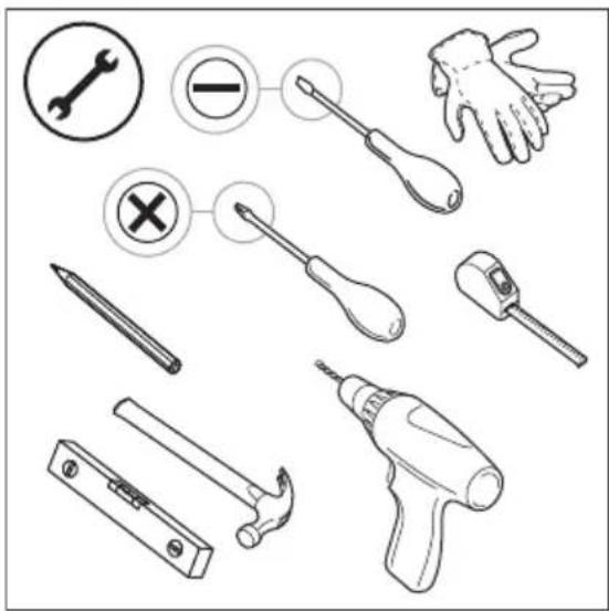
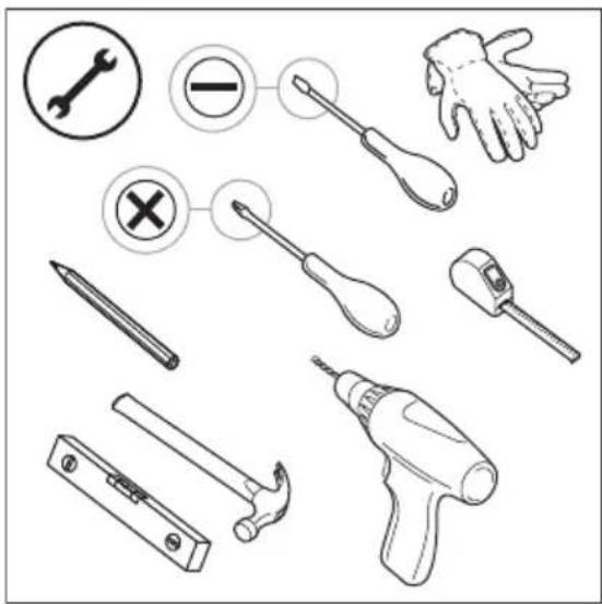
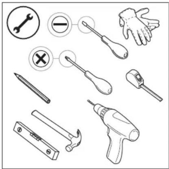
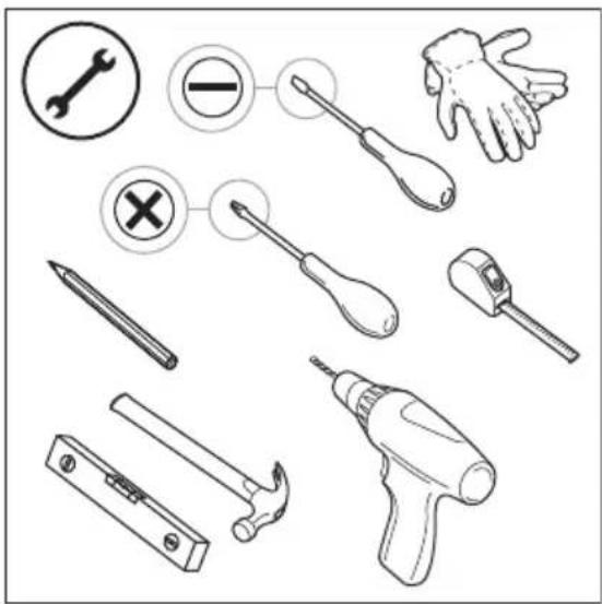
Tools required for installationFlathead screwdriver, drill, 6 mm drill bit, spirit level

Frequently Asked Questions - E9WHMIC1 AEG

How to install the AEG E9WHMIC1 filter?
Fix the wall bracket at 110 cm from the floor (tolerance ±5 cm) using the screws and anchors provided. Connect the hoses according to the INLET and OUTLET markings, then attach the filter body to the bracket until it clicks. Refer to the manual for installation videos.
Which washing machines is this filter compatible with?
It is compatible with household washing machines from Electrolux, AEG and Zanussi.
How often should I clean the filter cartridge?
Clean the cartridge once a week or as soon as the red float is visible in the cover.
How to clean the cartridge?
Unlock the cover, remove the cartridge, empty the water into a container, brush the mesh with the provided tool, then discard the residues in general dry waste. Reset the float by emptying the water from the cover.
When to replace the cartridge?
The cartridge has a lifespan of approximately 6 months. Replace it if the mesh is damaged. A spare cartridge is included in the box.
What to do in case of water leakage after installation?
Immediately stop the washing machine, unplug it, then check the clamps. Detach the filter from the bracket, tighten the clamps with a screwdriver, then reinstall. Check for leaks before reuse.
Can the filter be cleaned with water?
Avoid using water to clean the cartridge to prevent dispersing microfibers. Use the provided brush and discard dry waste. The filter water should not be reused.
What does the red float mean?
The red float indicates that the cartridge is full and the filter is operating in bypass mode without filtration. Clean the cartridge as soon as possible.
Can I use the filter with a top-loading washing machine?
Yes, the filter is compatible. Refer to appendix 2 of the manual for specific installation dimensions (height 110 cm, free space 40 cm).
Where can I buy a replacement cartridge?
Original replacement cartridges are available at authorized Electrolux/AEG service centers or online. Use only genuine parts.

User questions about E9WHMIC1 AEG

0 question about this device. Answer the ones you know or ask your own.

Ask a new question about this device

Your email remains private: it is only used to notify you if someone answers your question.

No questions yet. Be the first to ask one.

Download the instructions for your Water filter in PDF format for free! Find your manual E9WHMIC1 - AEG and take your electronic device back in hand. On this page are published all the documents necessary for the use of your device. E9WHMIC1 by AEG.

USER MANUAL E9WHMIC1 AEG

1. ⚠ SAFETY INFORMATION

Before the installation and use of the product, read the supplied instructions carefully. The manufacturer is not responsible for any injuries or damage that are the result of incorrect installation or usage. Always keep the instructions in a safe and accessible location for future reference.

- This product is designed for filtering microplastic fibres released from textiles during the washing process and should not be used for other purposes.

- This product can be used by children aged from 8 years and above and persons with reduced physical, sensory or mental capabilities or lack of experience and knowledge if they have been given supervision or instruction concerning the use of the product in a safe way and understand the hazards involved. Children of less than 8 years of age and persons with very extensive and complex disabilities shall be kept away from the appliance unless continuously supervised.

- Do not let children play with the product. Keep all packaging away from children and dispose of it appropriately.

- Children shall not carry out cleaning and user maintenance of the product without supervision. Keep detergents away from children.

- This product is intended to be used in household and similar applications such as:

- staff kitchen areas in shops, offices and other working environments;

- farm houses;

- by clients in hotels, motels, bed & breakfast and other residential type environments;

- areas for communal use in blocks of flats or in launderettes.

- Follow the installation instructions supplied with the product.

  • Do not install or use a damaged product or drain hoses. • Install the product in a safe and suitable place that meets installation requirements.
  • Do not install the product above any electrical sockets, or above any devices located on the wall, or freestanding devices close by on the floor to avoid the risk of electric shock.
  • Remove all the packaging.
  • Make sure the pipes are fixed properly to avoid leaks, noise or damage.
  • Ensure proper drain hose path between the appliance and the filter inlet to avoid blocking the drain flow.
  • Fixing devices for the wall are not included owing to different wall materials. Use proper fixing devices suitable for the walls.
  • Ensure that there are no visible water leaks during and after the first use of the product.
  • Do not use high pressure water sprays and/or steam to clean the product. Always switch off and check that the machine is not running before accessing or cleaning the product.
  • Clean the product with a moist cloth. Use only neutral detergents. Do not use abrasive products, abrasive cleaning pads, solvents or metal objects.
  • Clean the cartridge regularly, once a week or when the red floater indicator is clearly visible.
  • Do not reuse water from the filter. It may contain micro-plastic particles that are unfit for human and animal consumption. To repair the product contact the Authorised Service Centre. Use only original spare parts.
  • This external accessory is compatible with Electrolux/AEG/Zanussi household washing machines.

Environmental concerns

Recycle materials with the symbol. Put the packaging in relevant containers to recycle it.

2. INSTALLATION

2.1 Before Installation

AEG E9WHMIC1 - Before Installation - 1

WARNING!

Refer to Safety chapters.

AEG E9WHMIC1 - WARNING! - 1

Visit electrolux.com/getstarted/microplasticfilters for the installation and usage videos.

1. Select a proper location on the wall to install the filter:

To avoid leakages over the washing machine, it is preferable to install the filter on either side of your washing machine.
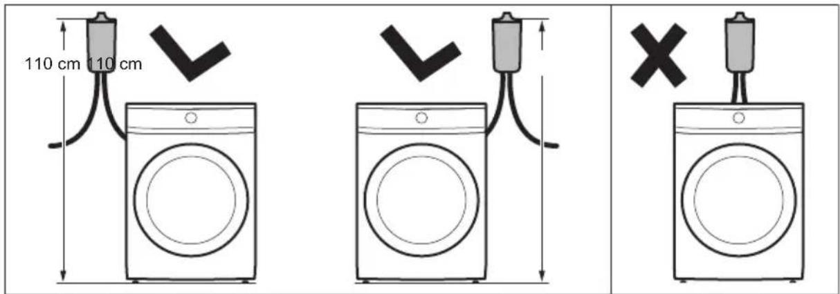
110 cm 110 cm 110 cm 110 cm 110 cm 110 cm 110 cm 110 cm 110 cm 110 cm 110 cm 110 cm 110 cm 110 cm 110 cm 110 cm 110 cm 110 cm 110 cm 110 cm 110 cm 110 cm

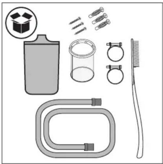
Illustration of cleaning and cleaning tools including a bottle, glass tube, brush, and tubing (no text or symbols).

  1. Verify box content.

Illustration showing various hand tools including wrench, screwdriver, hand, hammer, and power tool with corresponding icons.

  1. Prepare necessary tools for the installation.

2.2 Installing the accessory
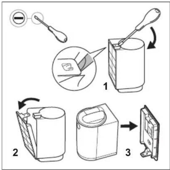
Diagram illustrating three-step cleaning process of a washing machine, showing tool insertion, cutting, and packaging steps.

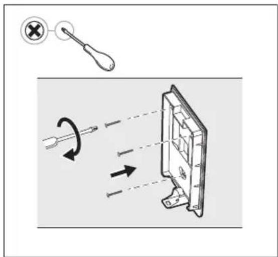
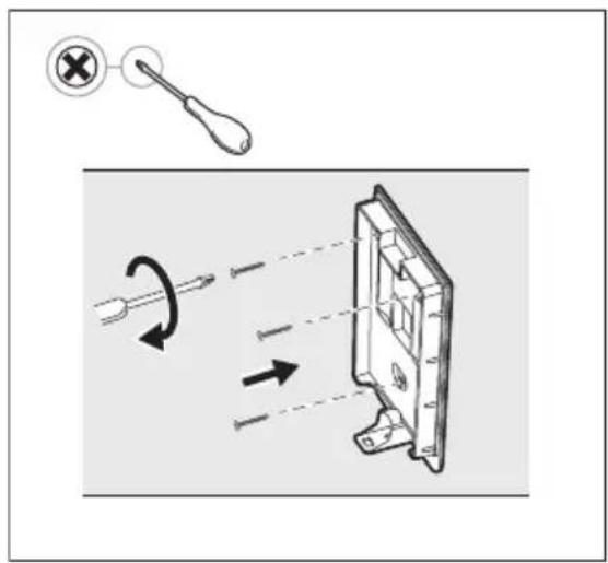
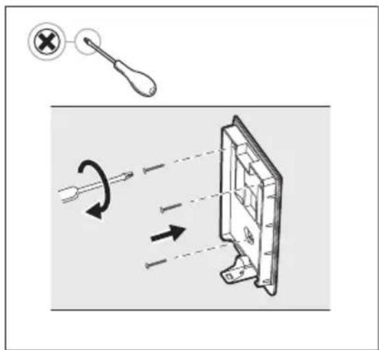
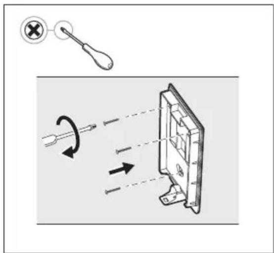
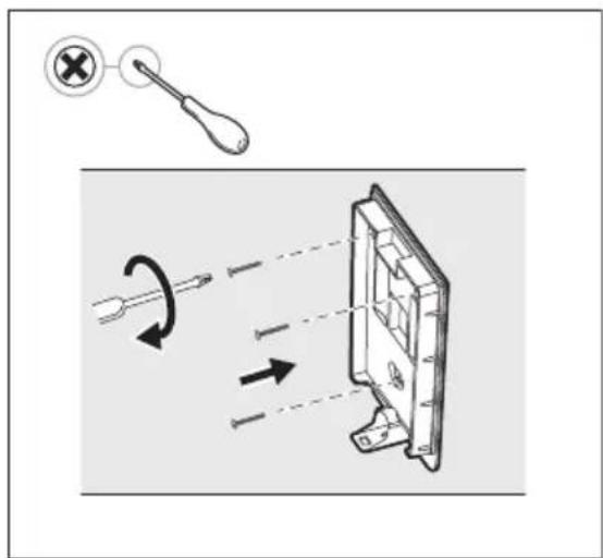
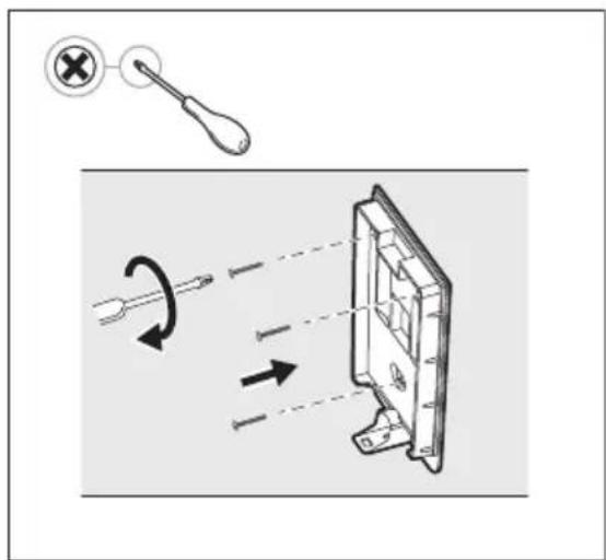
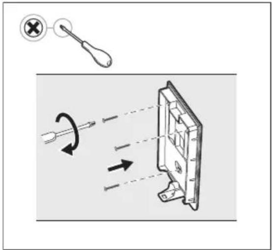
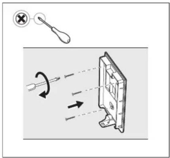
  1. Remove the filter from the packaging box and remove the wall support with the help of a flat screwdriver.
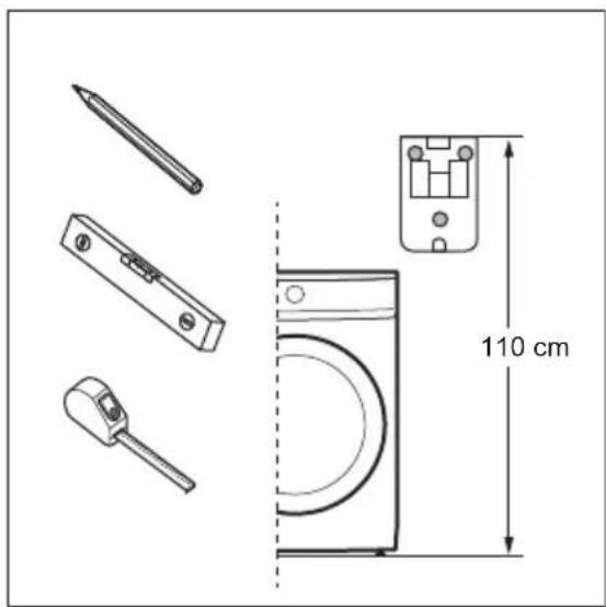
110 cm

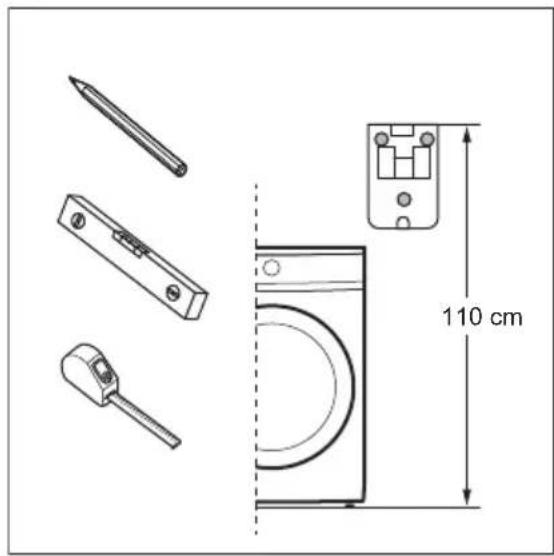
  1. The position of your filter needs to follow these listed points (a and b): a. Position the wall support at the correct height, measuring 110 cm* from the top of the wall support to the floor (or pedestal if present). *Tolerance admitted in filter height position is +/-5 cm.

AEG E9WHMIC1 - Installing the accessory - 3

Check where your point of drainage is before positioning the wall support. The filter is equipped with one drainage pipe with a length of 100 cm.

AEG E9WHMIC1 - Installing the accessory - 4

Make sure there is enough space above your filter before positioning the wall support. Be sure to leave adequate free space above the filter in order to remove and re-insert the cartridge. See minimum dimensions reference in Appendix 1 (Front Loader) and Appendix 2 (Top Loader).
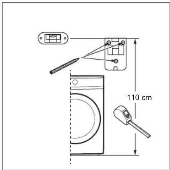
110 cm

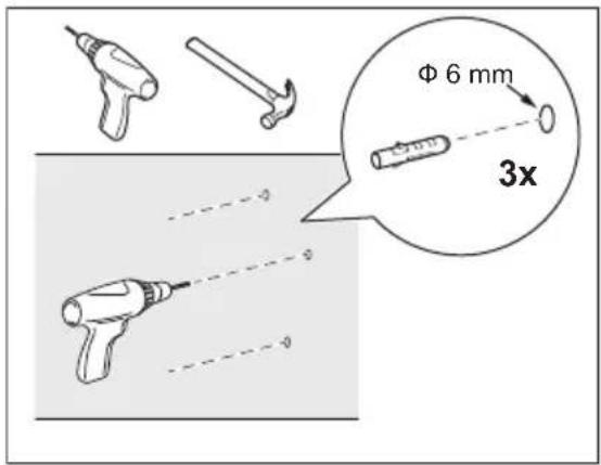
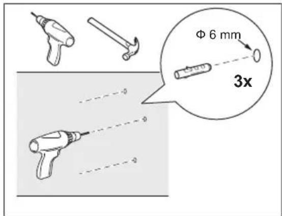
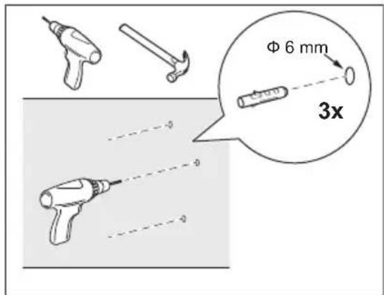
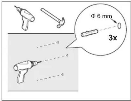
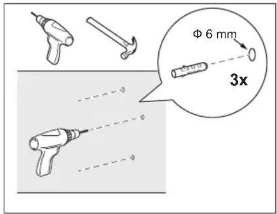
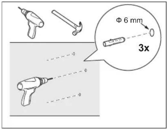
b. Use a level to check that the 3 drilling punches are level and well-aligned before drilling.
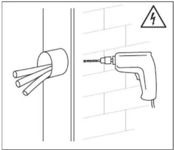
Diagram showing two electrical components: a cylindrical tube with wires inserted into a wall and a variable resistor, against a brick wall background (no text or symbols).

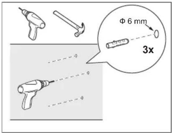
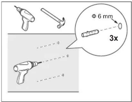
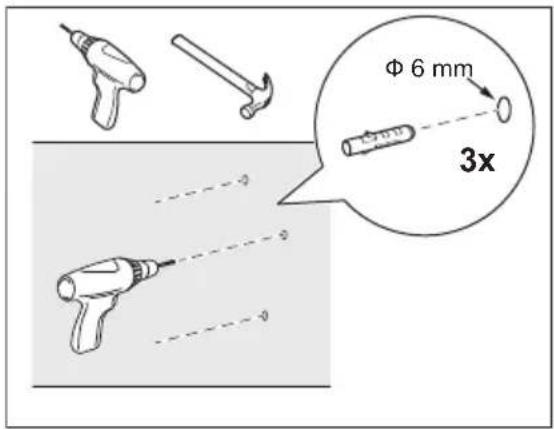
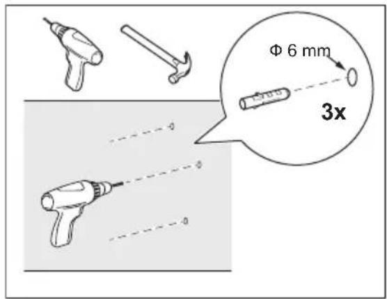
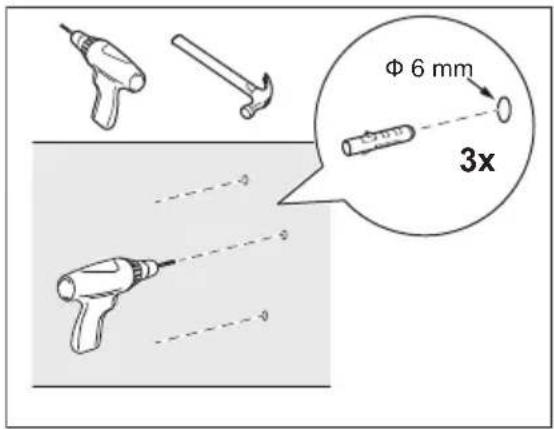
Φ 6 mm 3x

Diagram illustrating a screwdriver tool interacting with a mechanical component, showing motion and rotation directions.

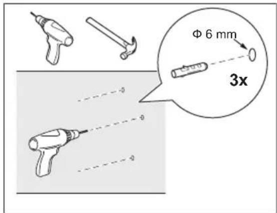
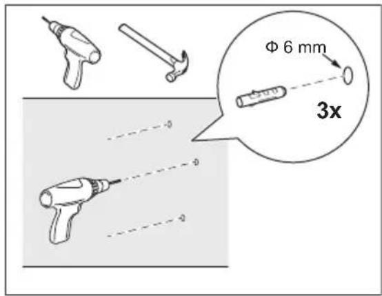
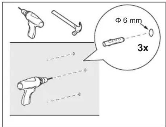
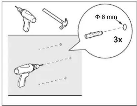
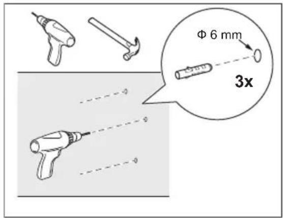
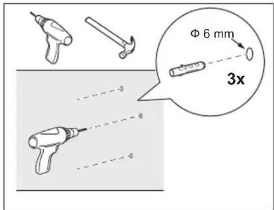
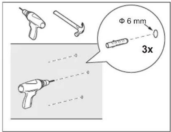
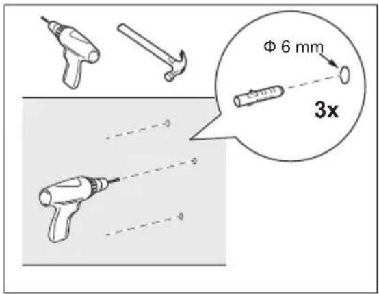
  1. Drill the holes into the wall and place the anchors.

WARNING!

Before drilling in the wall, make sure no water pipes or electrical wires are behind. It is recommended to use a φ 6mm drill bit. The filter package includes three dedicated screws and plastic anchors to properly and securely install the filter. The provided fixation system is designed for installation on a brick wall. In case of doubt, refer to the technician.

AEG E9WHMIC1 - WARNING! - 1

WARNING!

If your wall is made of different material than brick, use the proper anchors and screws designed for that material.

AEG E9WHMIC1 - WARNING! - 1

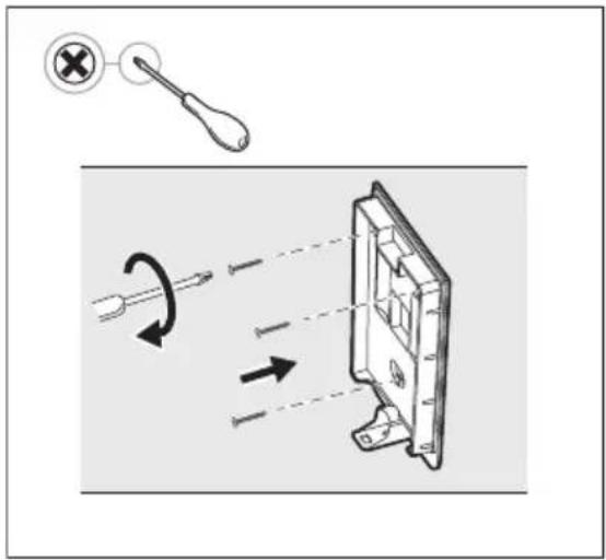
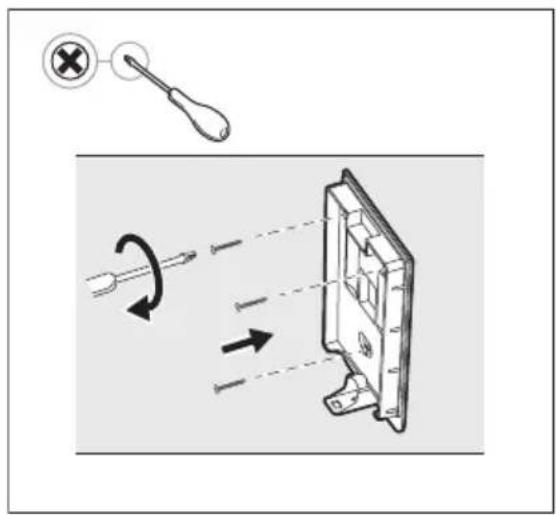
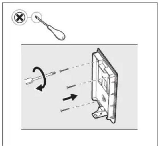
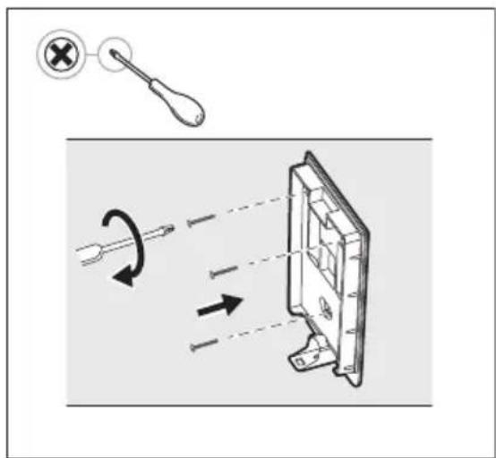
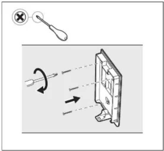
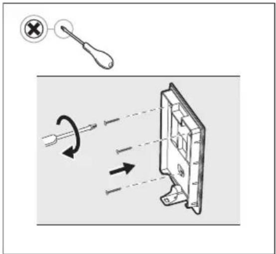
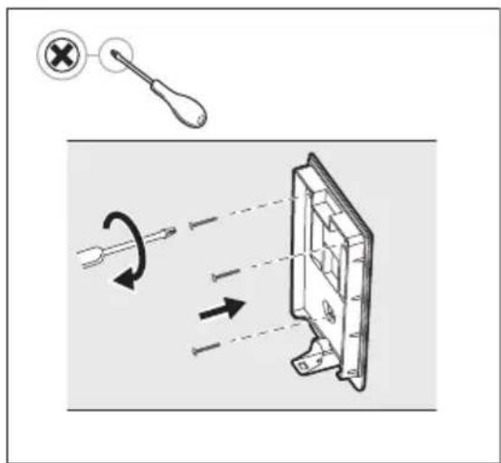
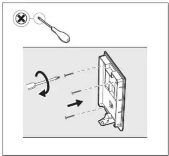
  1. Attach the wall support with the screws and plastic anchors provided, making sure it is straight and securely affixed to the wall.
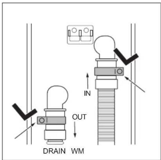
IN OUT DRAIN WM

5. Take the hoses, the collars and the filter body.

Insert the collars on the hoses and connect pipes to the filter body following IN/OUT indications present on the back of the filter body:

IN: hose which comes from the WM, OUT: hose (present in the filter package) which goes to the drain.

AEG E9WHMIC1 - Take the hoses, the collars and the filter body. - 1

WARNING!

Before connecting the drainage hose to the external filter, be sure that the washing machine is turned OFF and unplugged from the electrical socket.

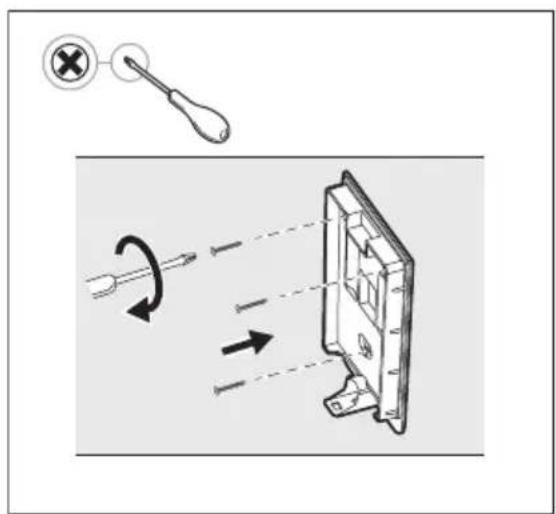
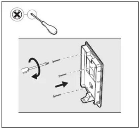
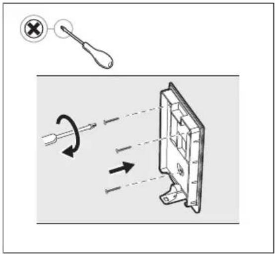
6. Tighten the collars using the screwdriver.

Follow these instructions exactly in order to position the collars to ensure a complete connection.
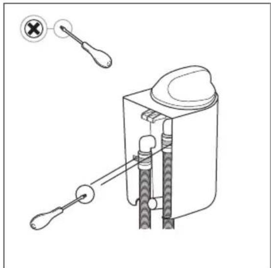
Technical line drawing of a mechanical device with tool tips and a close-up view showing a switch (no text or symbols).

AEG E9WHMIC1 - Tighten the collars using the screwdriver. - 2

When using the screwdriver, be careful not to damage the filter body or the hoses.

  1. Following the movement shown in the picture, when attaching the filter body to the wall support, you will hear a "click" as the body is correctly attached to the wall support.
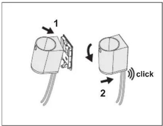
1 2 click

Diagram showing two steps of a mechanical device with labeled parts and directional arrows indicating motion.

AEG E9WHMIC1 - Tighten the collars using the screwdriver. - 5

Before proceeding to the next topic Daily use & care and cleaning, start the short washing programme and follow it until the end. Be sure that no leakages appear from the filter and its connections. In case of water leakage, proceed as described in paragraph 8. Detach the filter assembly from the wall support and tighten the collars. To reinstall the filter, repeat the steps in paragraph 7.
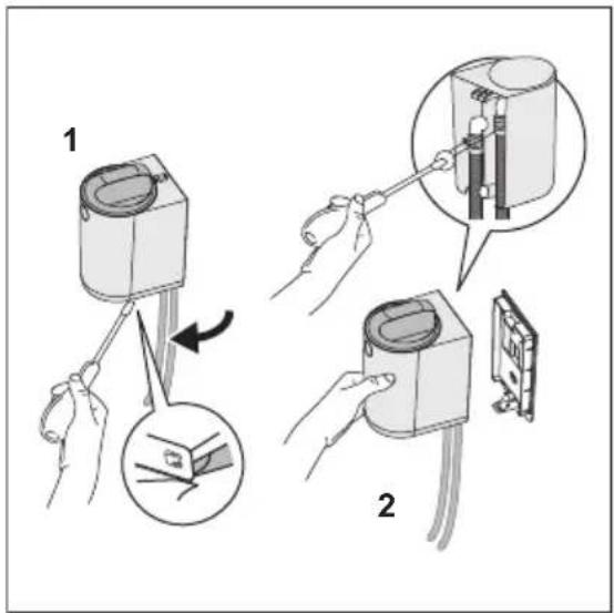
Diagram illustrating a procedure for inserting a device into a device, showing step 1 and step 2 with magnified views.

  1. If any water appears during first cycle, stop the programme immediately. Turn the washing machine OFF and unplug it from the electrical socket. Before proceeding with the detaching procedure, check that the filter cover stays in the locked position in order to avoid any water leakage while tightening the collars.

Detach entire filter from the wall support:

  1. Un-clip the filter from the wall support using the screwdriver,
  2. Hold the filter in your hand to tighten the collar with the screwdriver.

Repeat the steps in paragraph 7 to install the filter.

3. DAILY USE & CARE AND CLEANING

AEG E9WHMIC1 - DAILY USE & CARE AND CLEANING - 1

WARNING!

Refer to Safety chapters.

AEG E9WHMIC1 - WARNING! - 1

WARNING!

Always switch off and check that the machine is not running before accessing or cleaning the filter.

AEG E9WHMIC1 - WARNING! - 1

The filter cartridge is made with a thin Polyamide net in order to catch the microfibres released from the laundry washing process.

AEG E9WHMIC1 - WARNING! - 2

After some washing cycles, the filter cartridge will clog and must be cleaned.

AEG E9WHMIC1 - WARNING! - 3

The number of cycles before the activation of the floater will depend on several factors (kind of textile, drum size, most used programs, type of cycles and duration, laundry load, detergent, degree of soiling, etc.).

Clean the cartridge regularly, once a week or when the red floater indicator is clearly visible. When the filter is clogged, the red floater located inside the cover becomes visible, alerting the user that the cartridge needs to be cleaned, as shown in the next picture.

3.1 "Red alarm" condition
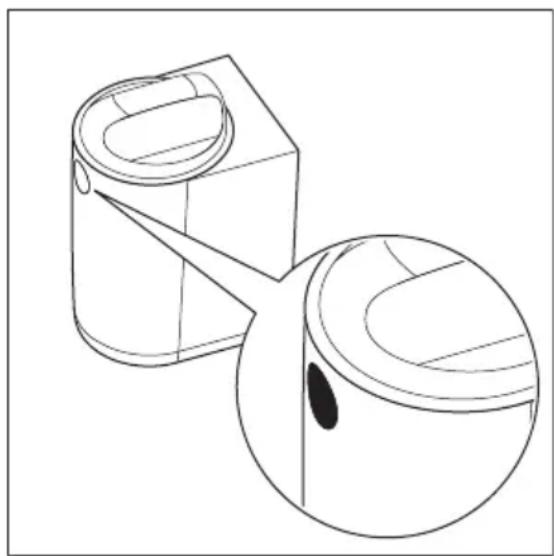
Technical line drawing of a cylindrical container with a side panel and an inset close-up of its lid (no text or symbols)

AEG E9WHMIC1 - "Red alarm" condition - 2

WARNING!

Do not reuse water from the filter. It may contain micro-plastic particles that are unfit for human and animal consumption.

AEG E9WHMIC1 - WARNING! - 1

Red floater indicates that the filter is full and needs to be cleaned.

In "red alarm" mode (when the floater is activated) the filter will not stop the washing cycle, but it will work in a bypass mode and will not filter anymore.

Therefore, to ensure optimal performance, it is recommended cleaning the cartridge as soon as possible to avoid leaving the filter in "red alarm" mode.

AEG E9WHMIC1 - WARNING! - 2

WARNING!

For several reasons the washing machine could show possible warnings, linked to draining issues, such as E20-E21. If this warning appears, first check the new external filter and clean it. If the error remains, check also the filter of your washing machine and clean it, if it is accessible.

Stopping the washing machine (error) is a safety feature of the machine to avoid long draining times and to not damage the machine. After the filter cartridge has been cleaned, normal operation can be resumed.

3.2 Care and Cleaning

Cleaning the filter and microfibres disposal.
  1. AEG E9WHMIC1 - Care and Cleaning - 1

Pure technical line drawing of a mechanical component with no text, numbers, or symbols

2.

Diagram showing two steps of a mechanical device: step 1 changes the internal component, and step 2 changes the interior.

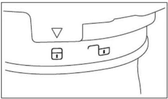
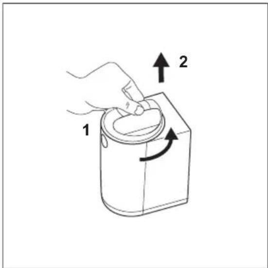
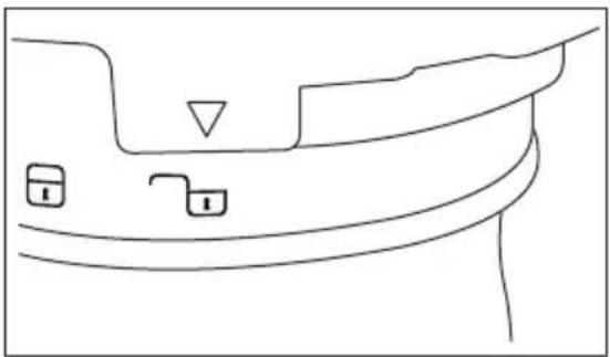
To open the filter, refer to the movements in Picture 1 and 2:

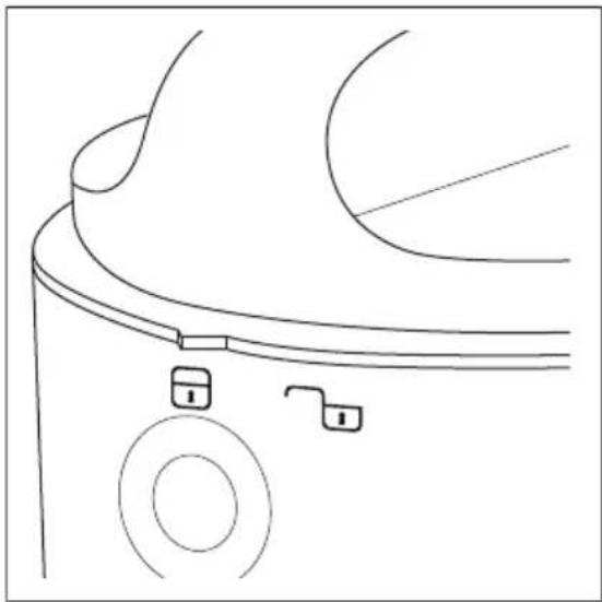
  1. Rotate the cover counter clockwise from lock symbol to unlock symbol (available on front of filter as shown in picture 2),
  2. Lift up the cover.

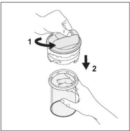
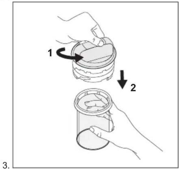
To detach the cartridge, refer to the movements in Picture 3:

  1. Hold the cover in your hand, then with the other hand rotate the cartridge counterclockwise from lock symbol to unlock symbol (see picture 4 and 5).
  2. Pull down the cartridge.

3.

4.

Line drawing of a mechanical component with two ports and a triangular feature (no text or symbols)

To Lock/Unlock the cartridge, refer to Picture 4 and 5:

Lock (picture 4) / Unlock (picture 5).

5.
Line drawing of a mechanical component with no visible text or symbols

i

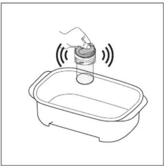
To clean the cartridge and dispose of its contents, refer to Picture 6, 7, 8 and 9.

6.
Line drawing of a hand pouring liquid into a container with sound waves (no text or symbols)

If the cartridge is fully clogged, it may be full of dirty water.

In order to be prepared for the cleaning operation, it is suggested to use any pot or small plastic container; this could help the operation and prevents the environment around from getting wet.

To remove the remaining water inside the cartridge, empty it out inside a pot or a container by holding the assembly cover and shaking it. The water flows out. In case some water still remains, proceed with the next step.

7
Three hands performing a mechanical press or rolling operation on a cylindrical object, shown in clockwise motion with arrows indicating rotation (no text or symbols present)

i

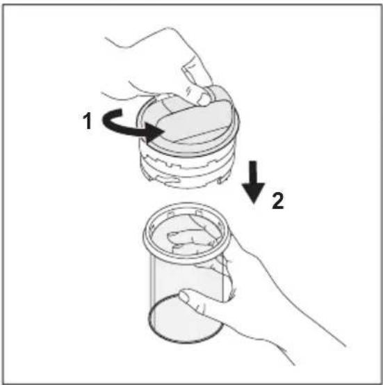
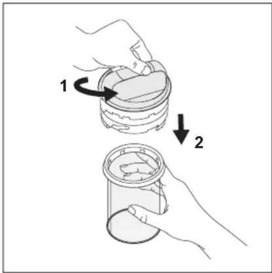
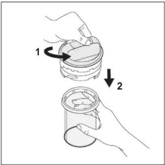
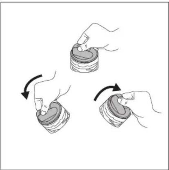
To reset filter, refer to Picture 7.

Before placing the cover back on the cartridge, reset the floater by removing water inside the cover. Hold the cover, rotate it (see picture 7) and drain all the water into a plastic container. The floater is no longer visible when the cover is placed on the filter.

A noise could be heard but this is normal behaviour since inside the cover there is a mass valve.
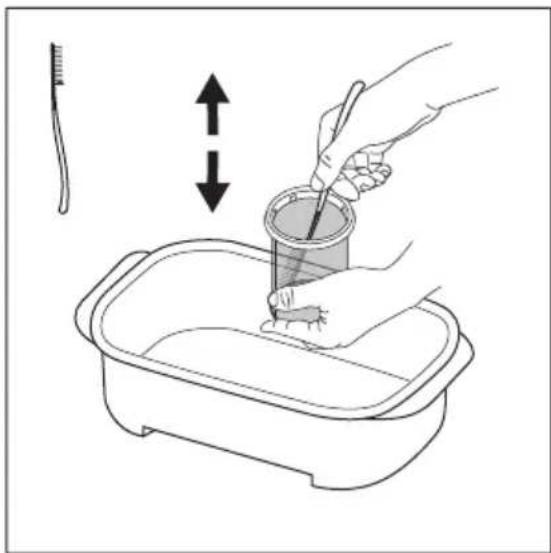
Illustration of a hand using a tool to clean or wash a small container in a basin, with no text or symbols present.

Holding the cartridge inside the container, use the brush-spatula tool available in the filter box. With up/down brush movement remove as much as possible the fibres attached to the cartridge net to help the evacuation of water.

AEG E9WHMIC1 - Care and Cleaning - 9

Dispose of waste from the filter into the general dry waste.
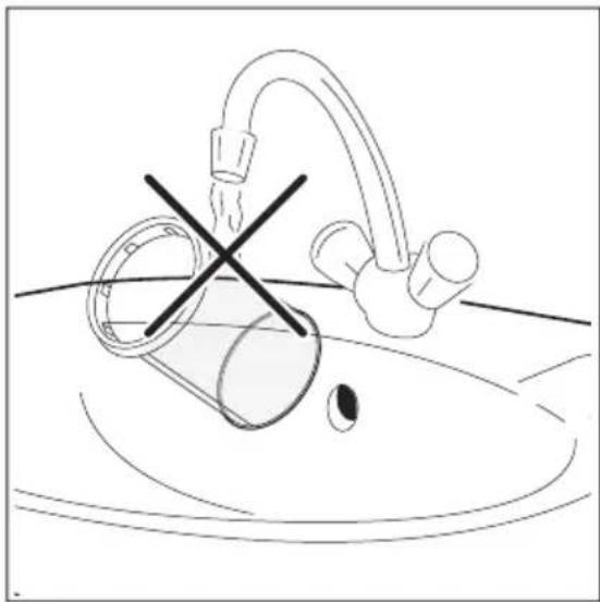
Simple line drawing of a faucet and pipe in a basin with a cross symbol indicating a crossed-out or no crossing (no text or labels)

To preserve the positive impact of the filter on the environment, avoid the use of water to clean the filter cartridge. Instead, throw away the waste collected by the filter cartridge in the general dry waste (avoid dispersion of plastic fibre in water ambient).
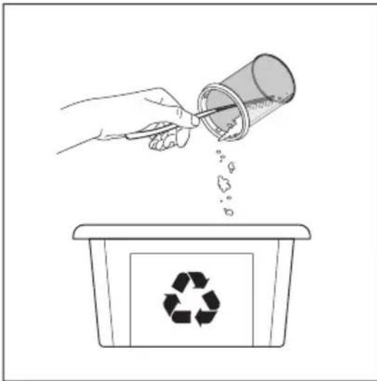
Illustration of a hand pouring liquid into a container with a recycling symbol (no text or labels)

After the water has been emptied from the cartridge, remove any dirt and microfibres from inside the cartridge and dispose of it in DRY general waste. A paper towel can be used to collect as much material as possible.

AEG E9WHMIC1 - Care and Cleaning - 12

CAUTION! Waste collected by the cartridge contains microfibres, detergent residuals and dirt. IT MUST be disposed of in general dry waste.

After the cartridge cleaning operation, the brush spatula could be dirty and full of plastic fibres. To preserve the positive impact on the environment, clean it with common paper towels and dispose of it to general dry waste
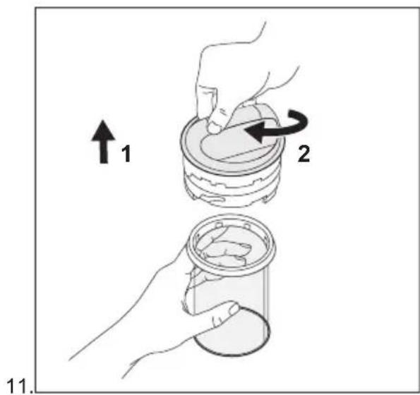
↑₁ 2 11.

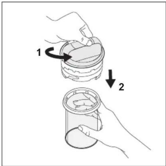
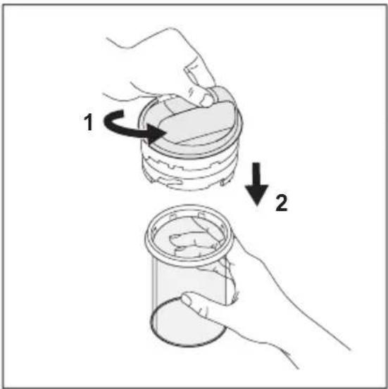
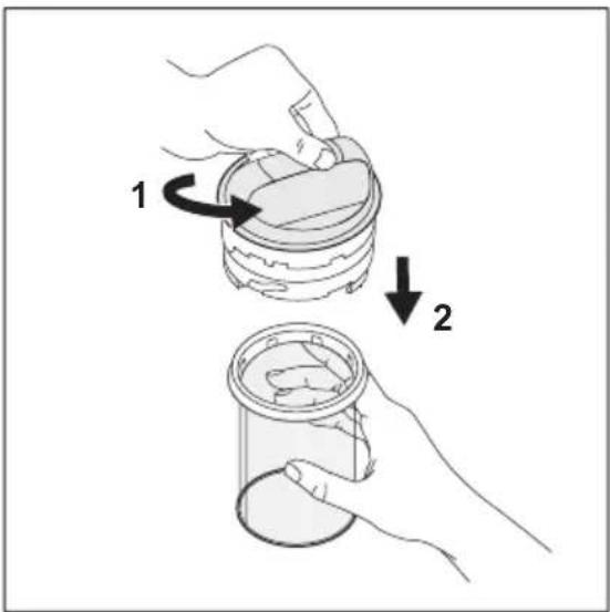
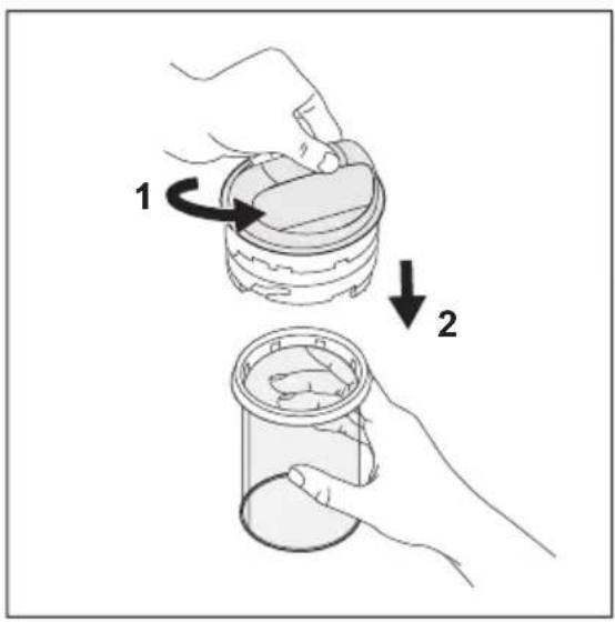
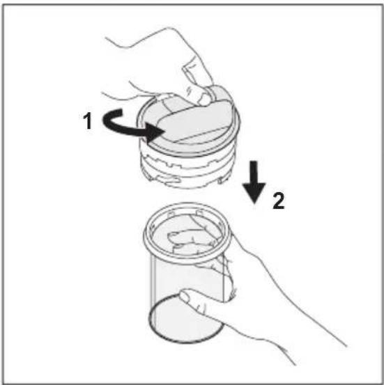
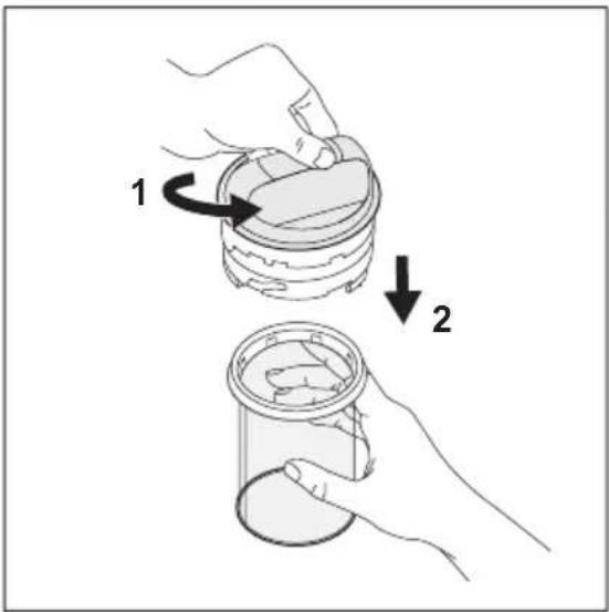
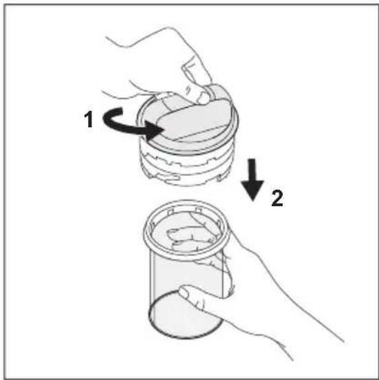
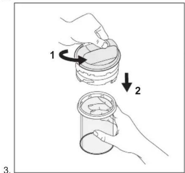
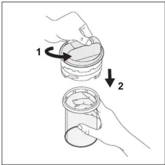
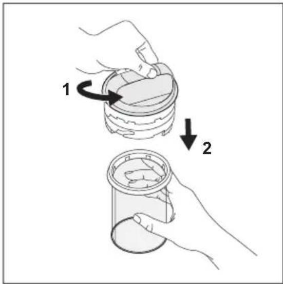
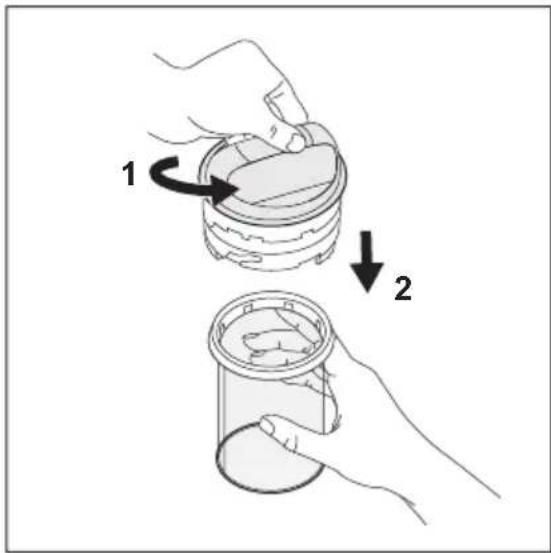
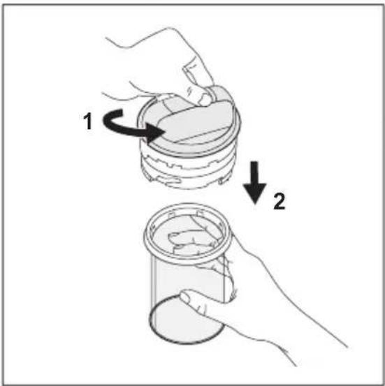
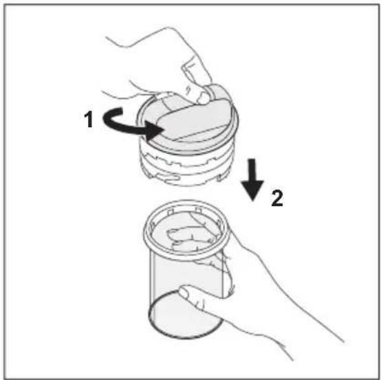
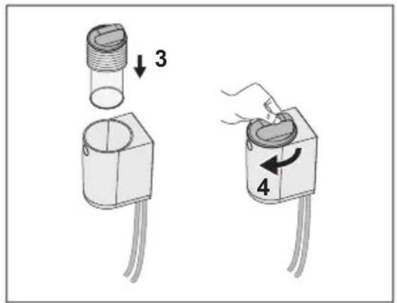
To replace the cartridge, refer to Picture 11:

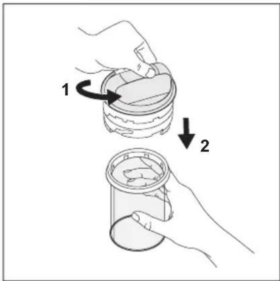
  1. Insert the cartridge.
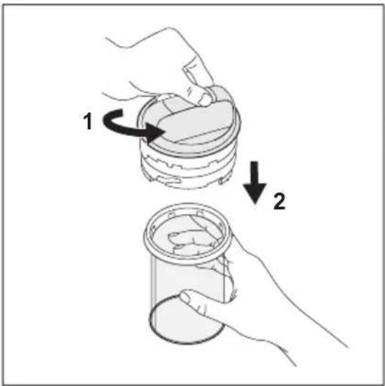
  2. Hold the cartridge in your hand, then with the other hand turn the cover clockwise from unlock symbol to lock symbol.
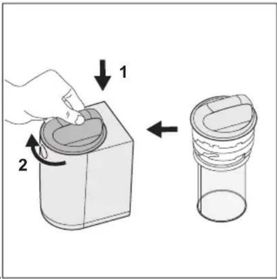
Diagram illustrating a mechanical assembly process with labeled steps 1 and 2, showing hand turning a component into a cylindrical device.

To close the filter, refer to the movements in Picture 12:

  1. Insert the cover (+ cartridge) inside the body from the top.
  2. Rotate the cover clockwise from the unlock symbol to the lock symbol.

For any additional information on maintenance and cleaning, please watch the video. A dedicated QR code is available at the beginning of this user manual.

CAUTION! Ensure to have closed lid before proceeding with the next washing cycle.

WARNINGS

In case of a washing break period longer than a full week (e.g. holiday, trip), it is suggested to empty the cartridge and clean the filter to avoid creation of unexpected smell into the environment of the filter.

It is necessary to clean the cartridge in wet condition in order not to damage it, avoiding the malfunctioning at next cycles used.

The filtration system is provided with spare a cartridge in order to restart immediately with your laundry routine in case of cartridge damage

Cartridge replacement and disposal

Cartridge has limited life, approximatively six months, since cleaning operation can damage the net, compromising filter performance. 1 spare cartridge part is included in the box.
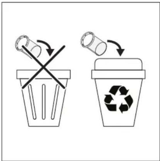
Diagram showing two waste sorting methods: one with a crossed-out bin and the other with a recycling symbol.

AEG E9WHMIC1 - Cartridge replacement and disposal - 2

Put the waste from the filter into a suitable recycling container.

When cartridge has to be replaced, please follow these 2 simple steps:

  1. Clean the damaged cartridge carefully.
  2. Put the cartridge and the waste into a recycle bin.

AEG E9WHMIC1 - Cartridge replacement and disposal - 3

For additional cartridge spare parts, use only original parts. Cartridges are sold at any Electrolux/AEG service center or online.

Appendixes
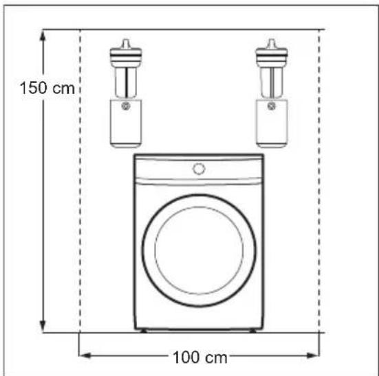
150 cm 100 cm

Appendix for Front Loader washing machine.
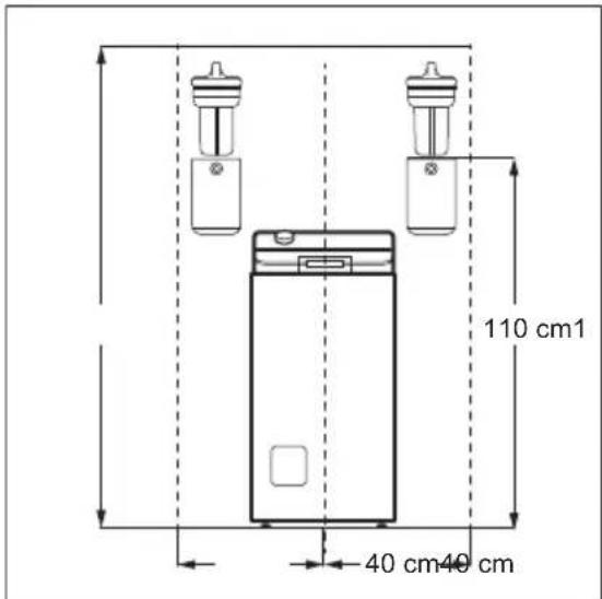
110 cm 1 40 cm 40 cm

Appendix for Top Loader washing machine.
Φ 6 mm 3x

Diagram illustrating a switch mechanism with labeled components and directional arrows indicating motion or flow.

Diagram showing two steps of a mechanical device with labeled parts and directional arrows indicating motion.

Diagram illustrating a mechanical device operation with labeled steps 1 and 2, showing hand positioning and assembly instructions.

  1. AEG E9WHMIC1 - Appendixes - 7

i

Diagram showing two waste sorting methods: one with a crossed-out bin and the other with a recycling symbol.

Illustration of cleaning tools including a bottle, cleaning cup, brush, hose, and screwdriver (no text or symbols).

Φ 6 mm 3x

Diagram illustrating a switch mechanism with labeled components and directional arrows indicating motion or rotation.

Diagram showing two steps of a mechanical device with labeled parts and directional arrows indicating motion.

Diagram illustrating a mechanical assembly process with labeled steps 1 and 2, showing hand positioning and component insertion.

i

  1. AEG E9WHMIC1 - Appendixes - 14

i

i

Diagram showing two waste sorting methods: one with a crossed-out bin and the other with a recycling bin, illustrating recycling or disposal concepts.

Illustration of cleaning tools including a bottle, glass tube, comb, and hose.

WARNING!

Diagram showing two steps of a mechanical device with labeled parts and directional arrows indicating motion.

Diagram illustrating a mechanical device operation with labeled steps 1 and 2, showing hand positioning and assembly instructions.

Line drawing of a hand pouring liquid into a container with sound waves. No text or symbols.

Illustration of a hand using a tool to clean or wash a container in a basin, with a brush and magnified view of the lid. No text or symbols.

Illustration of cleaning tools including a bottle, glass tube, brush, and tubing (no text or symbols).

Φ 6 mm, 3x

Diagram illustrating a switch mechanism with labeled components and directional arrows indicating motion or rotation.

Diagram showing two mechanical components with labeled parts and directional arrows indicating assembly or motion.

Diagram illustrating a mechanical assembly process with labeled steps 1 and 2, showing tool manipulation and component insertion.

i

2.

Diagram showing two steps of a mechanical device: step 1 changes the internal component, and step 2 changes the interior.

3.

Lock (picture 4) / Unlock (picture 5).

Line drawing of a hand pouring liquid into a container with sound waves (no text or symbols).

AEG E9WHMIC1 - WARNING! - 12

See picture 7 to reset the filter.

Diagram illustrating a mechanical assembly process with labeled steps 1 and 2, showing a hand pressing a component into a cylindrical container.

Diagram showing two waste sorting methods: one with a crossed-out bin and the other with a recycling symbol.

  1. Check the contents of the box.

Illustration showing various hand tools including wrench, screwdriver, hand, hammer, and power tool with corresponding icons.

Φ 6 mm 3x

Diagram illustrating a screwdriver tool interacting with a mechanical component, showing motion and rotation directions.

Diagram showing two mechanical components with labeled parts and directional arrows indicating assembly or motion.

Diagram illustrating two-step assembly steps of a device, labeled 1 and 2, showing tool path and component insertion.

Line drawing of a mechanical component with curved surfaces and circular features.

If the cartridge is completely clogged, it may be full of dirty water.

Diagram showing two waste sorting methods: one with a crossed-out bin and the other with a recycling symbol.

Dispose of the filter waste in a suitable recycling container.
Φ 6 mm 3x

Diagram illustrating a screwdriver tool interacting with a mechanical component, showing motion and rotation directions.

Diagram showing two steps of a mechanical device with labeled parts and directional arrows indicating motion.

Diagram illustrating a procedure for inserting a device into a device, showing step 1 and step 2 with magnified views.

2.

Diagram showing two steps of a mechanical device operation: first with rotation arrow, second with drop labeled '2'

AEG E9WHMIC1 - WARNING! - 27

2.1 Before installation

AEG E9WHMIC1 - Before installation - 1

WARNING!

  1. Check the contents of the box.

Illustration of various hand tools including wrench, screwdriver, hammer, and power tool with corresponding icons and symbols.

  1. Remove the filter from the packaging and remove the wall bracket using a flathead screwdriver.
110 cm

Φ 6 mm 3x

Diagram illustrating a screwdriver's turning process with labeled components and directional arrows

Diagram showing two mechanical components with labeled parts and directional arrows indicating assembly or motion.

  1. AEG E9WHMIC1 - WARNING! - 6

Illustration of a hand using a tool to clean or wash a container in a rectangular basin, with no text or symbols present.

Diagram showing two waste sorting methods: one with a crossed-out bin and the other with a recycling bin, illustrating recycling or disposal concepts.

Φ 6 mm 3x

Diagram illustrating a switch mechanism with labeled components and directional arrows indicating motion or rotation.

Diagram showing two mechanical components with labeled parts and directional arrows indicating motion or assembly.

Diagram illustrating two steps of a device operation, showing hand positioning and assembly with magnified views.

  1. AEG E9WHMIC1 - WARNING! - 13

Diagram showing two waste sorting methods: one with a crossed-out bin and the other with a recycling bin, indicating recycling or disposal.

Illustration of cleaning tools including a bottle, cleaning cup, brush, and tubing (no text or symbols)

Diagram showing two steps of a mechanical device with labeled parts and directional arrows indicating motion.

2.
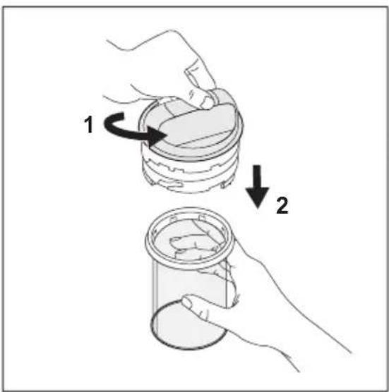
Diagram showing two steps of a mechanical device: step 1 changes the internal component, and step 2 changes the interior.

Illustration of a hand using a tool to clean or wash a container in a rectangular basin, with a brush and magnified view of the lid (no text or symbols)

Diagram showing two waste sorting methods: one with a crossed-out bin and the other with a recycling symbol.

Illustration of cleaning tools including a bottle, cleaning cup, brush, and tubing (no text or symbols)

Diagram illustrating a mechanical device operation with labeled steps 1 and 2, showing hand positioning and assembly instructions.

1 2 3.

Illustration of a hand using a tool to clean or wash a container in a basin, with no text or symbols present.

Diagram showing two waste sorting methods: one with a crossed-out bin and the other with a recycling symbol.

Illustration of various hand tools including wrench, screwdriver, hammer, and power tool (no text or symbols present).

Φ 6 mm 3x

Diagram illustrating a switch mechanism with labeled components and directional arrows indicating motion or rotation.

Diagram showing two steps of a mechanical device with labeled parts and directional arrows indicating motion.

  1. AEG E9WHMIC1 - WARNING! - 29

Diagram showing two waste sorting methods: one with a crossed-out bin and the other with a recycling symbol.

Illustration of various hand tools including wrench, screwdriver, hammer, and power tool.

Φ 6 mm 3x

Diagram illustrating a screwdriver tool interacting with a mechanical component, showing rotation and movement directions.

Diagram showing two steps of a mechanical device with labeled parts and directional arrows indicating motion.

Diagram illustrating two-step instructions for inserting a device into a battery, with labeled steps 1 and 2.

Pure technical line drawing of a mechanical component with no text, numbers, or symbols.

  1. AEG E9WHMIC1 - WARNING! - 37

Diagram illustrating a mechanical assembly process with labeled steps 1 and 2, showing a hand turning a component into a cylindrical device.

Diagram showing two waste sorting methods: one with a crossed-out bin and the other with a recycling symbol.

Illustration of cleaning tools including a bottle, glass tube, brush, hose, and screwdriver.

Φ 6 mm 3x

Diagram illustrating a screwdriver tool interacting with a mechanical component, showing motion and rotation directions.

Diagram showing two mechanical components with labeled parts and directional arrows indicating motion or assembly.

Diagram illustrating two-step assembly steps of a device, showing tool manipulation and component insertion.

Pure technical line drawing of a mechanical component with no text or symbols.

2.

1 2

i

i

Diagram showing two waste sorting methods: one with a crossed-out bin and the other with a recycling symbol.

Illustration of cleaning tools including a bottle, cleaning cup, brush, and tubing (no text or symbols).

Diagram showing two mechanical components with labeled parts and directional arrows indicating assembly or adjustment.

i

i

2.

Diagram showing two steps of a mechanical device: step 1 changes the internal component, and step 2 changes the interior.

i

Illustration of a hand using a tool to clean or wash a small container in a rectangular basin, with no text or symbols present.

Diagram showing two waste sorting methods: one with a crossed-out bin and the other with a recycling bin, illustrating recycling or disposal concepts.

Φ 6 mm 3x

Diagram illustrating a switch mechanism with labeled components and directional arrows indicating motion or rotation.

Diagram showing two steps of a mechanical device with labeled parts and directional arrows indicating motion or assembly.

Diagram illustrating a mechanical assembly process with labeled steps 1 and 2, showing hand positioning and component insertion.

i

2.
1 2

i

i

i

Illustration of cleaning and cleaning tools including a bottle, glass jar, hose, comb, and screwdriver (no text or symbols).

Φ 6 mm, 3x

Diagram illustrating a switch mechanism with labeled components and directional arrows indicating motion or rotation.

Diagram showing two mechanical components with labeled parts and directional arrows indicating assembly steps.

Diagram illustrating a mechanical device operation with labeled steps 1 and 2, showing hand positioning and assembly instructions.

Pure technical line drawing of a mechanical component with no text, numbers, or symbols.

  1. AEG E9WHMIC1 - WARNING! - 64

To lock/unlock the cartridge, refer to Figures 4 and 5:

i

To replace the filter, refer to Figure 7.

AEG E9WHMIC1 - To replace the filter, refer to Figure 7. - 1

To replace the cartridge, refer to Figure 11:

Illustration of cleaning tools including a bottle, glass jar, hose, comb, and screwdriver (no text or symbols)

Φ 6 mm 3x

Diagram illustrating a switch mechanism with labeled components and directional arrows indicating motion or rotation.

Diagram showing two mechanical components with labeled parts and directional arrows indicating motion or assembly.

  1. AEG E9WHMIC1 - To replace the filter, refer to Figure 7. - 6

Diagram showing two waste sorting methods: one with a crossed-out bin and the other with a recycling symbol.

Illustration of cleaning tools including a bottle, glass jar, comb, hose, and screwdriver (no text or symbols)

Diagram illustrating a mechanical assembly process with labeled steps 1 and 2, showing hand positioning and tool path.

Pure technical line drawing of a mechanical component with no text or symbols.

2.

1 2

Illustration of a hand using a tool to clean or wash a container in a basin, with no text or symbols present.

Diagram showing two waste sorting methods: one with a crossed-out bin and the other with a recycling symbol.

Illustration of cleaning and cleaning tools including a bottle, glass tube, brush, and tubing (no text or symbols).

Φ 6 mm 3x

Diagram illustrating a screwdriver tool interacting with a mechanical component, showing motion and rotation directions.

Diagram showing two mechanical components with labeled parts and directional arrows indicating motion or assembly.

Diagram illustrating a mechanical assembly process with labeled steps 1 and 2, showing tool manipulation and component insertion.

Line drawing of a mechanical component with curved surfaces and circular features (no text or symbols)

2.

1 2

3.

Φ 6 mm 3x

Diagram illustrating a screwdriver tool interacting with a mechanical component, showing motion and rotation directions.

3. Drill holes in the wall and insert wall plugs.

WARNING!

Diagram showing two mechanical components with labeled parts and directional arrows indicating assembly steps.

Diagram illustrating a mechanical assembly process with labeled steps 1 and 2, showing tool manipulation and component insertion.

Pure technical line drawing of a mechanical component with no text or symbols.

Diagram showing two waste sorting methods: one with a crossed-out bin and the other with a recycling symbol.

  1. Check the contents of the box.

Illustration of various hand tools including wrench, screwdriver, hammer, and power tool (no text or symbols present).

Φ 6 mm 3x

Diagram illustrating a screwdriver tool interacting with a door panel, showing motion and rotation directions.

  1. Drill holes in the wall and install the anchors.

WARNING!

AEG E9WHMIC1 - WARNING! - 1

Before drilling into the wall, make sure there are no water pipes or electrical wires behind it.

Diagram showing two steps of a mechanical device with labeled parts and directional arrows indicating motion.

Diagram illustrating two steps of a device operation, showing hand positioning and tool path changes.

i

  1. AEG E9WHMIC1 - WARNING! - 4

i

If the cartridge is completely clogged, it may be full of dirty water.

i

Diagram illustrating a mechanical assembly process with labeled steps 1 and 2, showing a hand pressing a component into a cylindrical container.

Diagram showing two waste sorting methods: one with a crossed-out bin and the other with a recycling symbol.

Illustration of cleaning tools including a bottle, cleaning cup, brush, and tubing (no text or symbols)

Φ 6 mm 3x

Diagram illustrating a switch mechanism with labeled components and directional arrows indicating motion or flow.

Diagram showing two steps of a mechanical device with labeled parts and directional arrows indicating motion.

Diagram illustrating a mechanical assembly process with labeled steps 1 and 2, showing tool manipulation and component insertion.

Pure technical line drawing of a mechanical component with no text or symbols

1 2 3.

i

i

ELECTROLUX APPLIANCES AB

BUSINESS SECTOR EMA-EMEA (SEE)

ST GÖRANSGATAN 143

SE-105 45 STOCKHOLM

SWEDEN

TEL: +46 (8) 738 60 00

FAX: +46 (8) 738 63 35

www.electrolux.com

Φ 6 mm 3x

Diagram illustrating screwdriver tool application on a device, showing rotation and movement of the component.

Diagram showing two steps of a mechanical device with labeled parts and directional arrows indicating motion.

Diagram illustrating a medical procedure for inserting a device into a device, with labeled steps 1 and 2.

  1. AEG E9WHMIC1 - WARNING! - 18

Diagram showing two waste sorting methods: one with a crossed-out bin and the other with a recycling symbol.

Illustration of cleaning and cleaning tools including a bottle, glass jar, tube, brush, and hose.

Φ 6 mm 3x

Diagram illustrating a switch mechanism with labeled components and directional arrows indicating motion or flow.

Diagram showing two steps of a mechanical device with labeled parts and directional arrows indicating motion.

Diagram illustrating a mechanical assembly process with labeled steps 1 and 2, showing tool manipulation and component insertion.

2.

1 2

3.

Illustration of a hand using a tool to clean or wash a container in a rectangular basin, with a brush and magnified view of the lid (no text or symbols).

AEG E9WHMIC1 - WARNING! - 27

Manual assistant
Powered by Anthropic
Waiting for your message
Product information

Brand : AEG

Model : E9WHMIC1

Category : Water filter