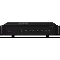
LA-402 - Receiver Monacor - Free user manual and instructions
Find the device manual for free LA-402 Monacor in PDF.


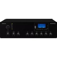
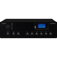
| Product type | Induction loop amplifier (receiver) |
| Brand | Monacor |
| Model | LA-402 |
| Dimensions (W x H x D) | Approx. 482.6 mm x 89 mm x 200 mm (estimate) |
| Weight | Approx. 4.5 kg (estimate) |
| Power supply | 230 V~ / 50 Hz |
| Power consumption | Not specified, max. 14 A loop current |
| Main features | Constant current amplifier for induction loop, area up to 750 m², 3 inputs (MIC/LINE), bass/treble controls, headphone output, MP3 playback from SD card, priority input, metal loss correction |
| Inputs | MIC: 1.5 mV/6.8 kΩ balanced (XLR), LINE XLR: 630 mV/10 kΩ balanced, LINE RCA: 630 mV/4.7 kΩ unbalanced, switchable 40 V phantom power |
| Outputs | Induction loop (screw terminals), headphone output (3.5 mm jack), SLAVE IN/OUT |
| Frequency response | 50 – 8000 Hz |
| Tone controls | Bass ±10 dB at 100 Hz, treble ±10 dB at 10 kHz |
| Max. loop current | 14 A |
| Permitted loop resistance | 0.2 – 2 Ω |
| Maintenance and cleaning | Dry, soft cloth, do not use chemicals or water |
| Safety | Do not open the device, unplug if damaged, use only indoors, temperature 0–40 °C |
| Spare parts and repairability | Replacement fuse (same type), repair by qualified technician |
| General information | Manual available in several languages, warranty void if used improperly |
Frequently Asked Questions - LA-402 Monacor
User questions about LA-402 Monacor
0 question about this device. Answer the ones you know or ask your own.
Ask a new question about this device
Download the instructions for your Receiver in PDF format for free! Find your manual LA-402 - Monacor and take your electronic device back in hand. On this page are published all the documents necessary for the use of your device. LA-402 by Monacor.
USER MANUAL LA-402 Monacor
Loop Amplifier for inductive audio transmission
LA-202
LA-202: 200m²
LA-402: .750m
Anschluss: . . . . . . . . . . . . . . . . . . . . . . . . . . . . . . . . . . . . . . . . . . . . . . . . . . . . . . . . . . . . . . . . . . . . . . . . . . . . . . ..
Eingänge
Loop amplifier for inductive audio transmission
These instructions are intended for installers with technical knowledge in inductive signal transmission. Please read the instructions carefully prior to operation and keep them for later reference.
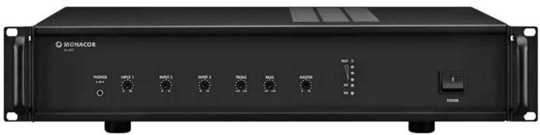
All operating elements and connections described can be found on the fold-out page 3.
Contents
1 Overview 8
1.1 Front panel 8
1.2 Rear panel 8
2 Safety Notes 8
3 Applications. 9
4 Setting Up. 9
4.1 Rack installation 9
5 Installation 9
5.1 Induction loop 9
5.1.1 Cable cross section 9
5.1.2 Connection of the induction loop . 9
5.1.3 Operation with two loop amplifiers . 9
5.2 Microphones 10
5.3 Units with line level 10
5.4 External switch for alarm announcements 10
5.5 Application in a PA system 10
5.6 Power supply. 10
6 Before Operation 10
6.1 First-time operation. 10
6.2 Metal loss correction 11
7 Operation 11
7.1 Protective circuit 11
8 Specifications 11
1 Overview
1.1 Front panel
1 3.5 mm jack for headphones; can be used to monitor the signal for the induction loop
2 Controls to adjust the volume of the input channels (INPUT 1 to INPUT 3)
3 Tone controls BASS = for the low frequencies TREBLE = for the high frequencies
4 Control MASTER for the field strength within the induction loop (maximum volume)
5 ON power LED
SIG signal LED with 3 LED level indicators above
PROT fault LED
6 POWER switch
1.2 Rear panel
7 Mains jack for connection to a socket (230V / 50Hz) via the mains cable provided
8 Support for the mains fuse Always replace a blown fuse by one of the same type!
9 Screw terminals LOOP OUTPUT to connect the induction loop
10 Screw terminalsMESSAGE TRIGGER for an external switch to replay the MP3 files (alarm announcements) from the memory card (18)
11 Control METAL LOSS CORRECTION (function only available with jumper J2 in position ON, refer to chapter 6.2)
12 Jack SLAVE IN / OUT to connect another loop amplifier (refer to fig. 4)
13 RCA input jacks INPUT 3 LINE to connect a (stereo) audio unit with line level output (CD/MP3 player, radio, mixer etc.)
14 XLR input jack INPUT 3 MIC for a microphone
15 DIP switches:
1 = phantom power for INPUT 3
2 = phantom power for INPUT 2
3 = input sensitivity for INPUT 2: microphone level or line level
16 XLR input jacks INPUT 1 and 2 for microphones or audio units
17 DIP switches for INPUT 1:
1 = priority function (INPUT 2 and 3 will be muted when a signal is applied)
2 = phantom power (40 V)
3 = input sensitivity of microphone level or line level
18 Slot for a memory card to replay alarm announcements (refer to item 10)
2 Safety Notes
The unit corresponds to all relevant directives of the EU and is therefore marked with

vents! Inexpert handling may result in electric shock.
Always switch off the induction loop system before making or changing any connections.
The unit is suitable for indoor use only. Protect it against dripping water, splash water and high air humidity. The admissible ambient temperature range is 0 - 40°C
- Do not place any vessel filled with liquid on the unit, e. g. a drinking glass.
The heat produced inside the unit must be dissipated by air circulation; never cover the air vents of the housing.
- Do not operate the unit or immediately disconnect the mains plug from the socket 1. if the unit or the mains cable is visibly damaged,
2. if a defect might have occurred after the unit was dropped or suffered a similar accident,
3. if malfunctions occur. In any case, the unit must be repaired by skilled personnel.
- Never pull the mains cable to disconnect the mains plug from the socket, always seize the plug.
- For cleaning only use a dry, soft cloth; never use water or chemicals.
- No guarantee claims for the unit and no liability for any resulting personal damage or material damage will be accepted if the unit is used for other purposes than originally intended, if it is not correctly connected or operated, or if it is not repaired in an expert way.
- Likewise, no liability will be accepted for any data loss as a result of operating errors or a defect or for any consequential damage caused by this data loss.

If the unit is to be put out of operation definitively, take it to a local recycling plant for a disposal which is not harmful to the environment.
3 Applications
LA-202 / LA-402 is a constant current loop amplifier with dynamic compressor. It is used for setting up an audio induction loop system. The amplifier is able to transmit audio signals to hearing aids with a "telephone coil" and to induction receivers (e.g. LR-202 from MONACOR). Wireless audio transmission is a great advantage of audio induction loop systems, allowing users total freedom of movement within the loop.
Audio induction loop systems are used for various applications, e. g. to provide assistance to people who are hard of hearing in churches, theatres, cinemas, waiting rooms and lounges, as interpreting systems, for lectures in museums, exhibitions etc.
In induction loop systems, a constant current amplifier will drive an induction loop. An induction loop consists of a loop of wire laid into the floor, wall or ceiling. Within this loop, a magnetic field is created which will induce a voltage in the induction receiver. The receiver will reconvert this voltage into an audio signal. Any number of receivers can be operated within an induction loop.
In ideal conditions, the induction loop of the amplifier will be able to cover an area of 200m2 (LA-202) 750m2 LA-402
In practice, however, this size may be reduced due to loss of field strength caused by metal in ceilings and floors.
4 Setting Up
The loop amplifier is designed for installation into a rack (482 mm / 19"), but it can also be placed on a table. To ensure sufficient cooling of the power amplifier, air must always be able to flow freely through all air vents.
4.1 Rack installation
Before installing the amplifier into a rack, use the jumper J2 to enable the metal loss correction, if required. Open the amplifier for this purpose (chapter 6.2).
For installation into a rack, fasten the two mounting brackets provided to the sides of the housing. In the rack, the loop amplifier requires a height of 2 RS (2 rack spaces = 89 mm).
To prevent the rack from becoming top-heavy, insert the amplifier into the lower section of the rack. The front panel alone is not sufficient for fixing it safely; additionally use lateral rails or a bottom plate to secure the unit.
5 Installation
CAUTION! Connections must be made by skilled personnel only. Always switch off the amplifier before making connections.
Hints
- Before installing the induction loop system, always use a receiver (e.g. LR-202) to check the desired place of installation for magnetic interference which may impair operation or even make operation impossible. Sources of interference are, for example, transformers, high-power cables, fluorescent lamps with conventional ballast and data cables.
- Apart from magnetic noise fields, reinforced concrete floors or underfloor heating with copper pipes may cause interference in induction loop systems. In this case, the magnetic field will not spread evenly and in the worst case, operation of an induction loop system will not be possible. In case of minor interference due to reinforced concrete, the control METAL LOSS CORRECTION (refer to chapter 6.2) can be used to match the frequency response accordingly.
- When laying the induction loop in tubes, make sure to use plastic tubes. Metal tubes may strongly affect the magnetic field of the loop.
5.1 Induction loop
The loop is laid around the perimeter of the sound reproduction area. The distance to ear level should be approx. 1m . It is strongly recommended to lay the loop at the same height. For the induction loop, a basic cable is used.
If local conditions make it impossible to lay the loop as a rectangle, a special loop design is required which must be calculated by an expert.
When the dimensions of the induction loop have been defined, calculate the cross section of the cable:
5.1.1 Cable cross section
The resistance of the loop must be 0.2 - 2Ω When the length of the loop has been measured, determine the cable cross section. Please refer to figs.5 and 6 for the required cross section of the defined cable length:

Fig. 5 Required cable cross section for the induction loop
| cable cross section in \( {\mathrm{{mm}}}^{2} \) | ||||||
| 0.5 | 0.75 | 1.0 | 1.5 | 2.5 | ||
| Loop length | min. at 0.2Ω max. at 2.0Ω | 6m 56m | 9m 84m | 12m 110m | 17 m 168 m | 28m 280 m |
Fig. 6 Minimum and maximum loop lengths for certain cable cross sections (copper)
For calculating the loop resistance (R) of a copper cable, the following formula can be used:
R = 1/A × ρ_ CU = 1/A × 0. 0 1 7 8 6 Ω × mm ^ 2m
A = Kcable cross section in mm²
I = loop length in m
ρcu = specific resistance of copper
5.1.2 Connection of the induction loop
The loop amplifier must be outside the loop (figs. 3 and 4).
1) Twist the cable section between the amplifier and the loop.
2) Before connecting the induction loop to the amplifier, use an ohmmeter to check and make sure that the loop is not earthed.
3) Connect the cable ends of the loop to the terminals LOOP OUTPUT (9).
5.1.3 Operation with two loop amplifiers
If one loop amplifier is not sufficient for the area required, two loops may be installed which are driven by one amplifier each. In this case, the first amplifier will operate as a master (to which all signal sources are connected) and the second as a slave.
Feed the audio signal from the master amplifier to the slave amplifier. Fig. 4 shows an example with adapters from the MONACOR product range:
1) Connect an adapter 6.3mm stereo jack/ 2× RCA inline jack (e.g. NTA-178) to the jack SLAVE (12) of the master unit. The output signal to be fed to the second loop amplifier is available at the tip of the 6.3mm plug.
2) When the jack SLAVE is used, the signal path between the mixer and the power amplifier will be disconnected. Therefore, use a Y-cable (e.g. CPR-25/BL) to be placed on the adapter NTA-178 to reconnect the signal path.
3) From the Y-cable, feed the output signal via an adapter cable 2 × RCA / 6.3mm stereo jack (e.g. MCA-302) to the jack SLAVE of the slave amplifier. The signal must be available at the ring of the 6.3mm stereo plug. Therefore, connect the red RCA plug of the cable MCA-302 to the Y-cable.
4) For first-time operation, use the controls MASTER (4) to adjust the current for the two induction loops separately on the master amplifier and on the slave amplifier (chapter 6.1).
5.2 Microphones
Up to three microphones can be connected to the XLR jacks INPUT 1 to INPUT 3 (14, 16). The microphone priority circuit can be activated for the microphone connected to the jack INPUT 1 (chapter 6.1, step 8).
1) When connecting a microphone to the channels INPUT 1 and 2, set the corresponding DIP switch 3 (15, 17) to the position MIC.
2) When using phantom-powered microphones, activate the 40V phantom power.
CAUTION! Only activate the phantom power when the amplifier has been switched off (loud switching noise possible). Make sure that no microphone with unbalanced output is connected to the corresponding input; this type of microphone may be damaged.
Set the corresponding DIP switch PH.PWR to the lower position ON:
| Channel | DIP switch |
| INPUT 1 | Item 17, No. 2 |
| INPUT 2 | Item 15, No. 2 |
| INPUT 3 | Item 15, No. 1 |
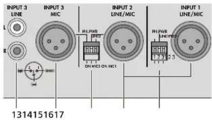
Fig. 7 Inputs and DIP switches
5.3 Units with line level
Up to three audio units with line output (e.g. CD/MP3 player, mixer, radio) can be connected to the XLR jacks (16) of the inputs 1 and 2 and to the RCA jacks (13) of input 3.
When using the XLR jacks, set No. 3 of the corresponding DIP switch (15, 17) to the
position LINE. Make sure to set the corresponding DIP switch PH.PWR (No. 2) to the upper position (OFF); otherwise, the unit connected may be damaged.
5.4 External switch for alarm announcements
Alarm announcements previously recorded in MP3 format on an SD memory card (e.g. from a computer) can be replayed via the amplifier, if required.
1) Insert the memory card containing the announcement/s into the slot ALARMMESSAGE (18),notched corner to the right, until it engages. To remove the card, push the card into the slot until it disengages.
2) Connect a switch to the terminals MESSAGE TRIGGER (10).
3) For replaying, close the switch: The MP3 files on the memory card will be replayed one after another and the volume of all other audio signals will be automatically reduced.
5.5 Application in a PA system
For integrating the loop amplifier into a PA system already in existence:
1) Feed the audio signal from the PA system to one of the jacks INPUT 1 to INPUT 3 (13, 16). The signal should have line level (0.2 - 1V) and be independent of the volume control of the PA amplifier.
2) When using one of the XLR jacks, set No. 3 of the corresponding DIP switch (15, 17) to the position LINE. Make sure to set the corresponding DIP switch PH.PWR (No. 2) to the upper position (OFF); otherwise, the unit connected may be damaged.
5.6 Power supply
Finally, connect the mains cable provided to the mains jack (7) first and then to a mains socket (230V / 50Hz)
6 Before Operation
6.1 First-time operation
1) The signal for the induction loop can be monitored via headphones (minimum impedance: 32Ω ). Connect the headphones to the jack PHONES (1).
2) Before switching on, set the controls INPUT 1 to 3 (2) and MASTER (4) to zero.
3) Switch on the amplifier with the POWER switch (6). The red LED ON (5) will light up.
4) Replay an alarm message that has been stored (or, if applicable, a test signal of 1kHz , 0 dB): Close the switch at the terminalsMESSAGE TRIGGER (10).
5) Slightly turn up the control MASTER and use a field strength meter to measure the field strength within the loop. The European standard EN 60118-4 recommends a field strength of 100mA / m ; the maximum field strength should not exceed 400mA / m . Both values are based on a reference frequency of 1kHz . Use the control MASTER to set the field strength accordingly. The LED chain (5) will indicate the output level.
If no field strength meter is available, use an induction receiver (e.g. LR-202 from MONACOR) to make the setting. Set the control MASTER to the highest audio and reception quality.
6) Feed a signal (test signal, piece of music or microphone announcement) to the inputs connected and use the corresponding controls INPUT (2) to adjust the volume.
7) Use the tone controls BASS and TREBLE (3) to adjust an optimum sound.
8) The signal of channel 1 may take priority over the channels 2 and 3. For this purpose, set No. 1 of the DIP switch PRIO (17) to the position ON. This will mute the signals of channels 2 and 3 when, for example, an announcement is made via channel 1. It will be easier to understand the announcement.
6.2 Metal loss correction
In many buildings, the metal content in ceilings and floors is very high. This metal may cause frequency-dependent loss of field strength. At a lower limit frequency between 0.01Hz and 100Hz ; the loss is 3dB / octave.
The metal loss correction will counteract this loss: Frequencies below 1kHz will be attenuated and frequencies above this value will be boosted by up to 3 dB / octave. Determining the effect of metal on the frequency response requires special equipment; it is difficult and involves a lot of effort. It is much easier to monitor the loop signal with an induction receiver (e.g. LR-202):
Activating and adjusting the correction feature
WARNING

For activating the metal loss correction, the unit must be opened. Therefore, only qualified personnel may do this. Risk of electric shock!
1) Disconnect the mains plug from the socket.
2) Unscrew the housing cover.
3) To activate the function, place the jumper J2 in position ON. The jumper can be found between the microfuse FU2 and the relay RY1.
4) Screw on the housing cover again.
5) For the time being, set the control METAL LOSS CORRECTION (11) to 0 dB.
6) Switch on the amplifier and, in case of an announcement, set the control METAL LOSS CORRECTION to optimum speech intelligibility.
7 Operation
It is not necessary to change the settings made in chapter 6. For normal operation, simply switch on the loop amplifier. Switch on the units of a PA system in the following order:
- the audio units (signal sources)
- the PA amplifier
- the loop amplifier
To switch off the system, proceed in reverse order.
7.1 Protective circuit
In case of a fault (failure, overheating), the red LED PROT (5) will light up and the signal for the induction loop will be turned off. In this case, switch off the amplifier and consult skilled personnel to eliminate the problem.
If the amplifier is overheated due to insufficient ventilation or extreme ambient temperature, it may be operated again after it has cooled down. Improve the ventilation, if required.
8 Specifications
Induction loop
Loop current
LA-202: 7 A max.
LA-402: 14A max.
Admissible
loop resistance: . . . . 0.2-2Ω
Max. coverage area
LA-202: 200m²
LA-402: .750m²
Connection: . . . . . . . . . . . . . . . . . . . . . . . . . . . . . . . . . . . . . . . . . . . . . . . . . . . . . . . . . . . . . . . . . . . . . . . . . . . . . . . . . . . . . . . . . . . . . . . . . . . . . Connection: .. .. .. .. screw terminals
Inputs
Sensitivity/Impedance; connection
MIC: 1.5mV/6.8kΩ;
XLR, balanced
Phantom power: 40 V, to be activated separately
LINE
XLR: 630 mV/10 kΩ; bal.
RCA: 630 mV/4.7 kΩ, unbalanced
Frequency range: .50-8000Hz
Tone controls
BASS: ±10 dB at 100 Hz
TREBLE: .±10dB at 10kHz
THD: < 1%
Ambient temperature: 0 - 40°C
Power supply: 230V/50Hz
Power consumption
LA-202: 150 VA max.
LA-402: 230VA max.
Dimensions
W×H×D: 482×88×280mm
2 rack spaces
Weight: 7 kg
Subject to technical modification.
Alimentation: 230V/50Hz
Consommation
LA-202: 150 VA max.
LA-402: 230VA max.
Dimensions
(1× h× p):482× 88× 280mm
2U
Poids: 7kg
LA-202: 200m²
LA-402: .750m
TREBLE: ... ±10dB a 10kHz
THD: < 1%
Temperatura ambiente: 0 - 40°C
LA-202: 200m²
LA-402: .750m


- LOOP AMPLIFIER FOR INDUCTIVE AUDIO TRANSMISSION
- CONTENTS
- 1 OVERVIEW
- 1.1 FRONT PANEL
- 1.2 REAR PANEL
- 2 SAFETY NOTES
- 3 APPLICATIONS
- 4 SETTING UP
- 4.1 RACK INSTALLATION
- 5 INSTALLATION
- HINTS
- 5.1 INDUCTION LOOP
- 5.1.1 CABLE CROSS SECTION
- 5.1.2 CONNECTION OF THE INDUCTION LOOP
- 5.1.3 OPERATION WITH TWO LOOP AMPLIFIERS
- 5.2 MICROPHONES
- 5.3 UNITS WITH LINE LEVEL
- 5.4 EXTERNAL SWITCH FOR ALARM ANNOUNCEMENTS
- 5.5 APPLICATION IN A PA SYSTEM
- 5.6 POWER SUPPLY
- 6 BEFORE OPERATION
- 6.1 FIRST-TIME OPERATION
- 6.2 METAL LOSS CORRECTION
- ACTIVATING AND ADJUSTING THE CORRECTION FEATURE
- WARNING
- 7 OPERATION
- 7.1 PROTECTIVE CIRCUIT
- 8 SPECIFICATIONS
Brand : Monacor
Model : LA-402
Category : Receiver