
FC 260 - Fan QLIMA - Free user manual and instructions
Find the device manual for free FC 260 QLIMA in PDF.

| Product type | Ceiling fan |
| Brand | Qlima |
| Model | FC 260 |
| Power supply | Input: 100-240 V~, 50/60 Hz, 1.5 A Output: 24 V⎓, 3 A, 72 W |
| Power | 72 W (output) |
| Remote control | Yes, with RF synchronization |
| Mobile app | Yes, compatible with Smart Life (Wi-Fi 2.4 GHz) |
| Motor | Reversible (summer/winter mode) |
| Speed | Adjustable with Nature mode |
| Lighting | Integrated LED, brightness and color temperature adjustable (warm/cool white) |
| Tilt angle | Suitable for sloped ceilings up to 25° (longer rod required) |
| Minimum mounting height | 2.1 m (7 ft) / 2.3 m (Europe) |
| Number of blades | 3 |
| Maintenance | Clean with a soft cloth; check screws twice a year |
| Safety | Installation by a qualified electrician; safety cable; approved outlet box |
| Warranty | 24 months |
| Standards | EN 60335; FCC Part 15 |
| Included accessories | Power adapter, remote control, mounting kit, screws, lower rod, lampshade |
| Usage | Indoor only |
| Protection rating (adapter) | IP20 |
Frequently Asked Questions - FC 260 QLIMA
User questions about FC 260 QLIMA
0 question about this device. Answer the ones you know or ask your own.
Ask a new question about this device
Download the instructions for your Fan in PDF format for free! Find your manual FC 260 - QLIMA and take your electronic device back in hand. On this page are published all the documents necessary for the use of your device. FC 260 by QLIMA.
USER MANUAL FC 260 QLIMA
natural_image
Black and white photo of a three-blade propeller with a circular head cover (no text or symbols visible)guarantee
2
YEARS
| D | BEDIENUNGSANLEITUNG | 2 |
| F | MANUEL D’UTILISATION | 22 |
| GB | OPERATING MANUAL | 42 |
| I | ISTRUZIONI D’USO | 60 |
| NL | GEBRUIKSHANDLEIDING | 80 |
(Abb. 1)
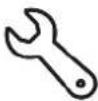
Externer
Maulschlüssel
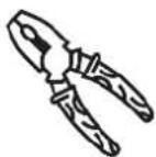
Abisolierzange Kreuz-
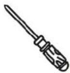
schraubendreher
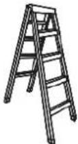
Trittleiter
(Abb.3)
AUFBAU
FLÜGEL INSTALLIEREN
natural_image
Diagram of a propeller assembly with internal components and a magnified view showing internal structure (no text or labels)(Abb. 6)
(Abb. 7) (Abb. 8)
MONTAGE
natural_image
Diagram of a ceiling fan assembly with a close-up inset showing the component being adjusted (no text or symbols present)(Abb. 18)
(Abb. 22)
(Fig. 1)
natural_image
Two line drawings of pliers and screwdrivers (no text or symbols)(figure 4) (figure 5)
INSTALLEZ UN ABAT-JOUR
natural_image
Diagram of a propeller assembly with internal components and a close-up inset showing mechanical parts (no text or labels)(figure 6)
(figure 7) (figure 8)
ASSEMBLAGE
FIXATION DU VENTILATEUR
natural_image
Diagram of a mechanical assembly with a component and a magnified inset showing a close-up of the component (no text or symbols present)(figure 18)
Make sure all wires are tucked in the canopy. Connect the AC input to the house electricity.
(figure 22)
INSTRUCTIONS D'UTILISATION DE LA TÉLÉCOMMANDE :
SYNCHRONISATION DE LA TÉLÉCOMMANDE AVEC VOTRE VENTILATEUR
CONDITIONS DE GARANTIE
Congratulations with the purchase of your ceiling fan. You have acquired a high quality product which will give you many years of pleasure, if you use it responsibly. Please read the user's manual first in order to ensure the optimum life span of your ceiling fan. On behalf of the manufacturer, we provide a two-year warranty on material- or manufacturing defects.
Enjoy your ceiling fan.
Yours sincerely,
PVG Holding B.V.
Customer Service Department
1 PLEASE READ THE USER'S MANUAL FIRST.
2 IF YOU HAVE ANY DOUBTS, CONSULT YOUR DEALER.
(Fig. 1)
(Fig. 2)
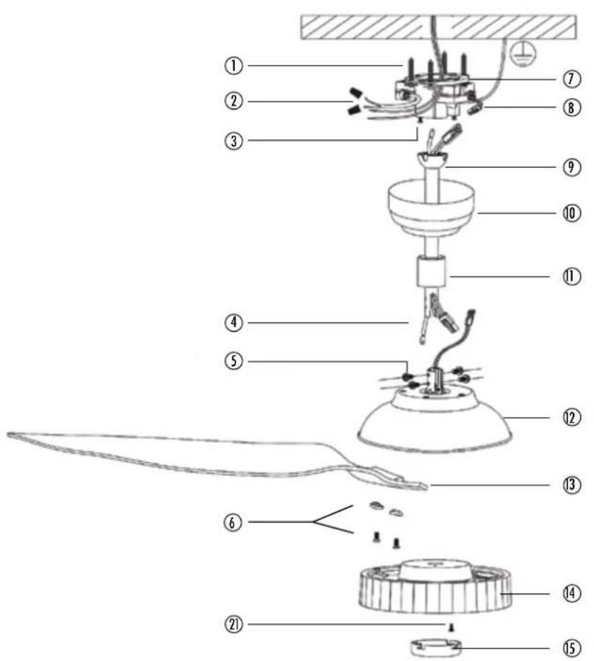
IMPORTANT COMPONENTS
① ST5x24 Setscrew
② Input AC 100-240V
③ M4x10 Screws
4 Safety Cable
⑤ M6x12 Rod Screw
6 M6x12 Airfoils' screw
⑦ Mounting bracket
8 AC Adapter
9 Downrod
10 Canopy
⑪ Wiring cover
⑫ Motor hub
13 Airfoils
14 Lampshade
15 Lower cover
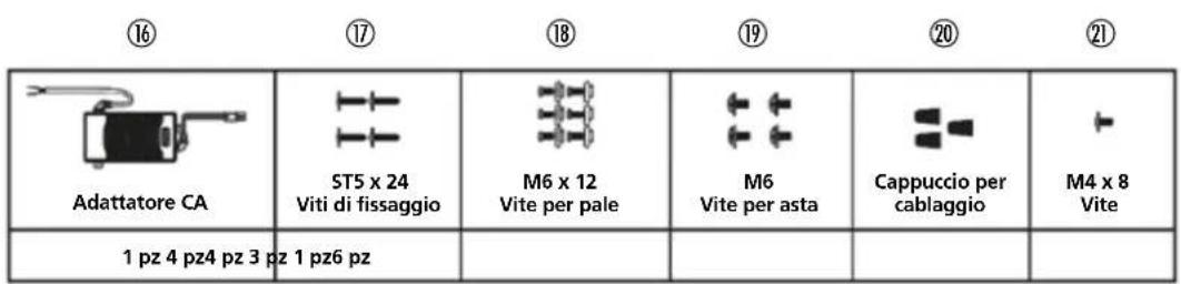
16 AC Adapter
17 ST5x24 Setscrew
18 M6x12 Airfoil's screw
19 M6x12 Rod screw
20 Wiring cap
21 M4x8 screw
DIRECTIONS FOR USE (GB)
- Read this user manual carefully before using the appliance and keep it for future reference. Install this device only when it complies with local/national legislation, ordinances and standards.
- The electric ceiling fan is designed for indoor use.
- After unpacking, check the appliance for any damages. When in doubt, do not use the appliance, but contact customer service at your local dealer's. Keep the packaging materials (plastic bags, etc.) away from children, as they may cause hazardous situations to children.
- No modifications to the safety system are allowed.
- This product is constructed in conformity with relevant texts in the EN 60335 standard

SAFETY PRECAUTION:
Important: please read before installation:
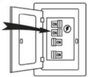
- Before you begin installing the fan, shut power off at the circuit breaker of the fuse box.
- CAUTION: Read all instructions and safety information before installing your new fan. Review accompanying assembly diagrams.
- Make sure that all electrical connections are in accordance with National Electrical Code, ANSI/NFPA 70 and local codes. Hire a licensed electrician if you are unfamiliar
with installing electrical wiring.
- Make sure the installation site you choose allows the fan blades to rotate without any obstructions. Allow a minimum clearance of 2.1m (7 feet) from the floor and 18 inches from the tip of the blades to the wall.
- WARNING: To reduce the risk of fire, electric shock, or personal injury, mount to outlet box marked "Acceptable for Fan Support of 15.9 kg (35 lbs) or less" and use mounting screws provided with the outlet box.
- CAUTION: To reduce the risk of injury, use only the screws provided with the outlet box in conjunction with the lock washers provided with the fan.
- The outlet box and support structure must be securely mounted and capable of reliably supporting a minimum of 35 pounds. Use only CE. Listed outlet boxes marked "Acceptable for Fan Support of 15.9 kg (35 lbs) or less".
- After you install the fan, make sure that all mounting components are secured to prevent the fan from falling.
- Do not insert anything into the fan blades while the fan is operating.
- To change the direction of the rotation of the blades the fan must be in operation mode.
- All set screws must be checked and retightened where necessary before installation.
- WARNING: To reduce the risk of personal injury, do not bend the blade bracket when installing the brackets, balancing the blades, or cleaning the fan. Do not insert
foreign objects in between rotating fan blades.
- CAUTION: To reduce the risk of electric shock, disconnect the electrical supply circuit to the fan before installing light kit.
- After making the wire connections, the wires should be spread apart with the grounded conductor and the equipment-grounding conductor on one side of the outlet box and the ungrounded conductor on the other side of the outlet box.
- The splices after being made should be turned upward and pushed carefully up into the outlet box. Conductor wiring identified as grounded is to be connected to a grounded conductor of power supply. Conductor wiring identified as ungrounded conductor is to be connected to an ungrounded conductor. Conductor wiring identified for equipment grounding is to be connected to an equipment-grounding conductor.
- This device complies with part 15 of the FCC Rules. Operation is subject to the following two conditions: (1) This device may not cause harmful interference, and (2) this device must accept any interference received, including interference that may cause undesired operation.
- WARNING: To reduce the risk of fire or electric shock, this fan must be installed with a general use, isolating wall control/switch.
WARNING: To reduce the risk of fire or electric shock, do not use this fan with any solid-state speed control device.
NOTE: The important safeguards and instructions appearing in this manual are
not meant to cover all possible conditions and situations that may occur. It must be understood that common sense, caution and care are factors which cannot be built into this product. These factors must be supplied by the person (s) installing, caring for and operating the unit.
- Please remember to respect the local regulations: hand in the non-working electrical equipments to an appropriate waste disposal centre. The packaging material is recyclable. Dispose of the packaging in an environmentally friendly manner and make it available for the recyclable material collection-service.
- This appliance is only intended to be used in indoor use.
- This appliance can be used by children aged from 8 years and above and persons with reduced physical, sensory or mental capabilities or lack of experience and knowledge if they have been given supervision or instruction concerning use of the appliance in a safe way and understand the hazards involved. Children shall not play with the appliance. Cleaning and user maintenance shall not be made by children without supervision.
- Regarding the instructions for cleaning and maintenance, please refer to the corresponding paragraph of the manual.
- WARNING: If unusual oscillating movement is observed, immediately stop using the ceiling fan and contact the manufacturer, its service agent or suitably qualified persons.
- The fixing means for attachment to the
ceiling such as hooks or other devices shall be fixed with a sufficient strength to withstand 4 times the weight of the ceiling fan;
- That the mounting of the suspension system shall be performed by the manufacturer, its service agent or suitably qualified persons;
- That the fan is to be installed so that the blades are more than 2.3 m above the floor(Europe only);
- That the fan is to be installed so that the blades are more than 2.1 m above the floor(Australia only);
- The model or type reference of a luminaire that may be installed in a fan constructed for this purpose.
- The external flexible cable or cord of this luminaire cannot be replaced; if the cord is damaged, the luminaire shall be destroyed.
CAUTION: The light source is designed for this specific application and can overheat if serviced by untrained personnel. If any servicing is required, the product should be returned to an authorized service facility for examination or repair.
If you fail to consult and/or follow up the rules, instructions and explanation, the warranty will no longer be valid, and the manufacturer will no longer deal with any damage to the appliance and/or your environment under the warranty.
BEFORE YOU START
Contact a licensed electrician if you are uncomfortable performing electrical work. A licensed electrician must install the fan if required by local code. Do not use the fan with a dimmer switch. Turn off power at breaker.
TOOLS AND MATERIALS REQUIRED

(Fig. 3)
INSTALLATION:
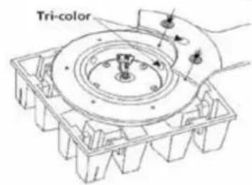
INSTALL AIRFOILS
1.1 Put out the motor hub from the package box and place it upside down on the motor paper holder. Make sure each airfoil matches the corresponding place with the tri-color label on the hub and tighten the screws. (See Fig 4)
1.2 Three airfoils installed. (See Fig 5)
(Fig.4)

natural_image
Diagram of a mechanical assembly with hands holding a circular component and a directional arrow (no text or symbols)(Fig.5)
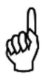
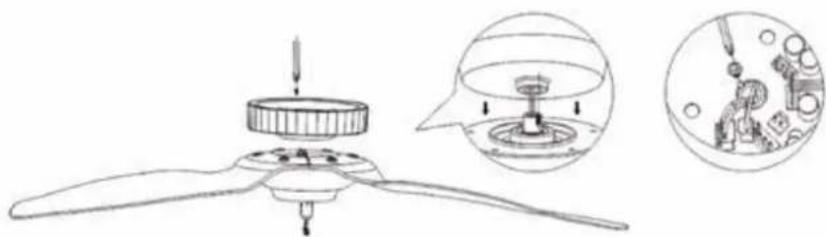
INSTALL LAMPSHADE
2.1 Place lampshade onto the motor hub.
Join the slot of lampshade and slot of motor shaft by tightening the screw that provided in screw bag. (See Fig 6)
natural_image
Diagram of a propeller assembly with a close-up view showing internal components (no text or labels)(Fig. 6)
2.2 Insert the 2P terminal and the 3P terminal into the corresponding terminal interfaces on the circuit board, and then install the M4x8 screw to secure the lampshade in place. (See Fig 7)
2.3 Snap the small cover into the hole of the lampshade and tighten it in the direction indicated by the arrow. (See Fig 8)
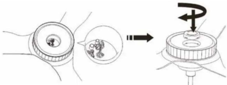
(Fig. 7) (Fig. 8)
Warning: Make sure you tighten the screw to secure the lampshade, otherwise the lampshade will loosen or drop down when the fan is running.
ATTACH DOWNROD
3.1 Assemble down rod as pictured in Fig.9. (Please select the suitable length of rod for your ceiling.)
NOTE: If you choose to install a safety Cable/chain onto your ceiling fan, you will need to run it through the downrod prior to installation.
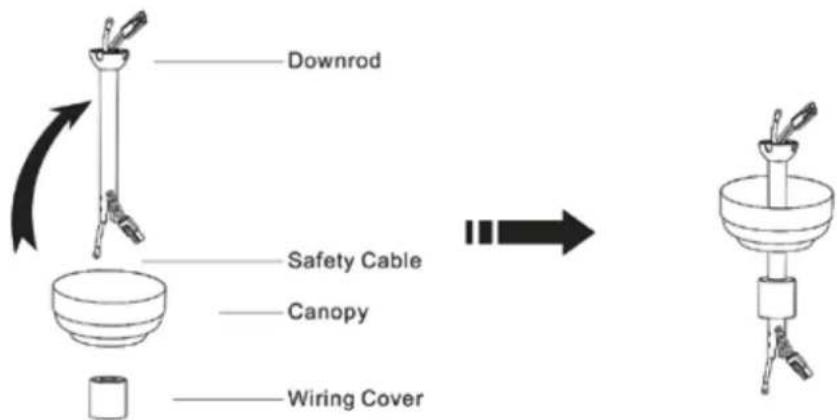
(Fig. 9)
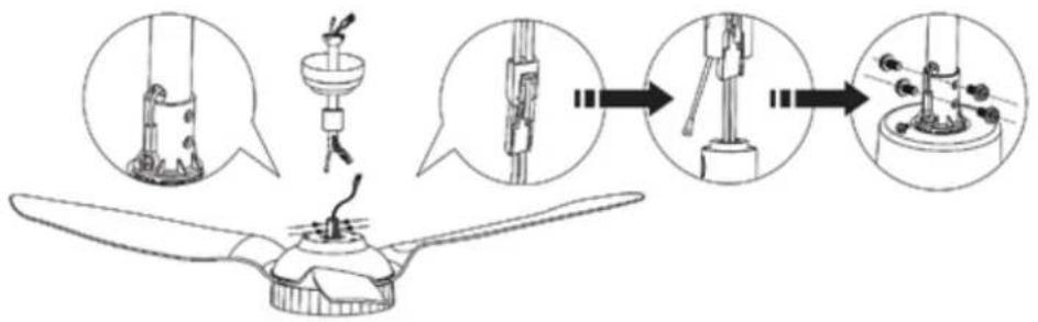
3.2 Remove the screw which already fixed in side of motor shaft, then connect the safety cable with motor shaft firmly by this screw. (See Fig 10)
Connect the wiring harness from the down rod to the receptacle from the motor wire as Fig.11. After finished, hide the wire into down rod.
NOTE: Take out the end of the safety cable from downrod before lowering the downrod onto motor hub.(See Fig 12)
Install the screws and washers in opposite directions from each other (2 sets on each side) and make sure the screws and washers are tightened firmly with a screwdriver.(See Fig 13)
(Fig. 10) (Fig. 11) (Fig. 12) (Fig. 13)
ASSEMBLY
HANGING THE FAN
Install the mounting bracket to the ceiling box, as shown in Fig 14 below. Rotate the mounting bracket in different directions so that the bracket mounting holes match the screw holes of the ceiling box.
Note: This mounting bracket is a standard cable box. If the mounting bracket is installed at the outlet box, it should be installed on the outlet box with two screws matching the outlet box itself, as shown in Fig 14.
This bracket can also be mounted to the wooden ceiling beam, and then the four STx24 screws can be used to lock the corresponding holes on the left and right sides of the bracket.
Note: The wooden ceiling beam must meet the tensile test of 30KG for installation, as shown in Fig 15. It is also possible to install the mounting bracket directly to the concrete ceiling and install four screws to the left and right corresponding holes of the bracket to lock the ceiling, as shown in Fig 16.
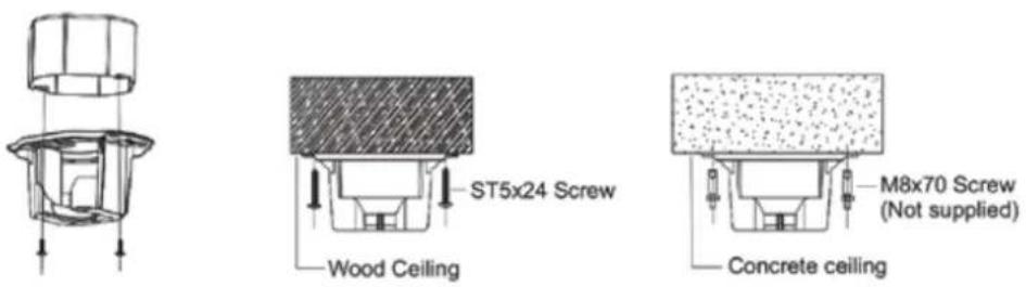
(Fig. 14) (Fig. 15) (Fig. 16)
If you have an angled or vaulted ceiling: (Fig 17)
- When installing the mounting bracket, the bracket groove is upward.
- You will need a longer downrod.
- If your ceiling angle is wider than 25^ , you will also need an Angled Mounting Kit.
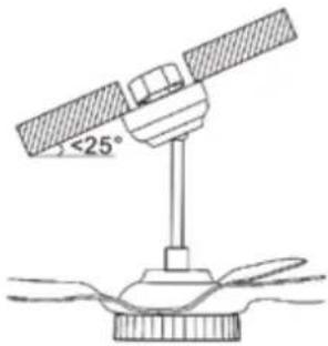
(Fig. 17)
HANGING CEILING FAN & INSTALLING POWER ADAPTER & WIRING THE FAN:
WARNING: To reduce the risk of fire, electric shock or other personal injury, mount the fan only to an outlet box or supporting system marked acceptable for fan support and use the mounting screws provided with the outlet box.
WARNING: Check to see that all connections are tight, including ground, and that no bare wires are visible at the wire nuts (except for the ground wire).
WARNING: To reduce the risk of fire or electric shock, do not use this fan with any solid-state speed control device.
WARNING: To avoid possible electrical shock, be sure electricity is turned off at the main fuse box before wiring.
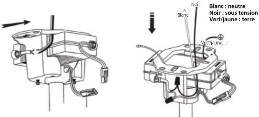
Hang the installed ceiling fan on the mounting bracket that mounted to the ceiling as shown in Fig 18, pay attention to the enlarged image as shown in Fig 18. The pivot ball on the down rod needs to hang from inside the socket of the bracket and match up with a slot to lock the pivot ball in place.
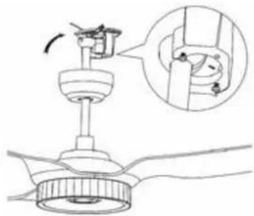
natural_image
Diagram of a mechanical assembly with a component and a magnified inset showing a close-up view of the component (no text or symbols present)(Fig. 18)
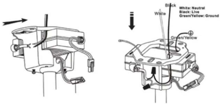
Connect the wire of the power adapter through the bracket as below Fig 19:
The wires will need to be bound together with electrical tape for added stability. Put the AC Adapter inside the bracket and connect the DC output wire with the wire from motor through the downrod.
Make sure all wires are tucked in the canopy. Connect the AC input to the house electricity.
WARNING: Put AC adapter into the flat side of bracket and push it through to the other side which the ceiling fan hangs from. Please see the Arrow direction showed in Fig 19, otherwise the wires are too short to be connected.
Note: The Green/Yellow wire from bracket connects with the ground wire from supply power, using the wiring cap to tuck the wires together and then hide inside the ceiling.
The White wire from AC Adapter connects with the Neutral wire from supply power, the Black wire from AC Adapter connects with the Live wire from supply power, using the wiring cap to tuck the wires together. (Make sure all the wires connect with the correct colors as shown below Fig 19)
(Fig. 19)
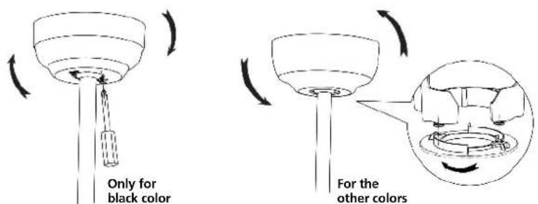
RAISE CANOPY
For the ceiling fan with black color, canopy installation as below:
Make sure all wires are tucked in the canopy. Raise the canopy to the mounting bracket, aligning the two screws on the canopy with the holes on the bracket, Secure the canopy to the mounting bracket with the screws, see Fig 20.
For the ceiling fan with other colors, canopy installation as below:
Make sure all wires are tucked in the canopy. Raise the canopy to the mounting bracket, align the two screws into the slot inside the canopy, rotate and twist the canopy to lock into place. See Fig 21.
Installation is now complete. Turn on the power switch as Fig 22. Then the fan lights are on. Test and pair your fan immediately using the remote control.
(Fig. 20) (Fig. 21)
GB
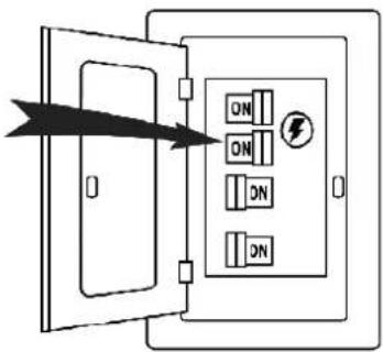
(Fig. 22)
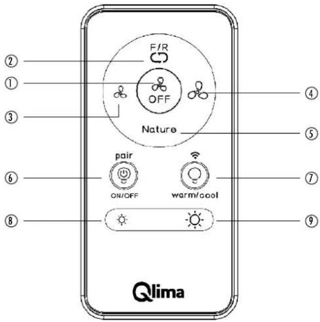
REMOTE CONTROL OPERATING INSTRUCTIONS
PAIRING THE REMOTE CONTROL TO YOUR FAN
Within 10 min. of plugging fan to power source, press and hold ⏻ button for 5 sec. to pair remote control and fan. Successful pairing will trigger beep alert.
Remote Control
(Fig. 23)
REMOTE CONTROL BUTTON DEFINITIONS
- Turns the fan off.
- Switch between summer mode and winter mode.
- Summer mode - (Counter-clockwise) A downward airflow creates a cooling effect. - Winter model - (Clockwise) An upward airflow moves warm air off the ceiling area and redistributes the warm air that hovers around the ceiling to the living space.
-
Turns the fan on and decreases fan speed.
-
Turns the fan on and Increases fan speed.
-
Switch the fan speed between nature mode and normal mode. Simulate a natural breeze to make you comfortable when you sleep.
Note: Press/hold this button for 5 sec. to turn off the beep. Press/hold button for 5 sec. again to turn it on.
- Turns the lights on or off and RF pairing.
Note: Press/hold button for 5 sec. within 10 min. of plugging fan to power source to pair remote and fan.
- Switch between warm light and cool light. WIFI Trouble shootings.
Note: Press/hold button for 5 sec. till beep alert. The fan will switch to AP Mode, then select AP Mode on APP, follow the APP control instructions will enable fan Wi-Fi.
-
Press/Hold button to decrease the desired light level.
-
Press/Hold to button to increase the desired light level.
Warning: Do not expose the remote control to rain or water.
Install / Replace Batteries
Use two dry alkaline batteries (1.5V). Do not use rechargeable batteries.
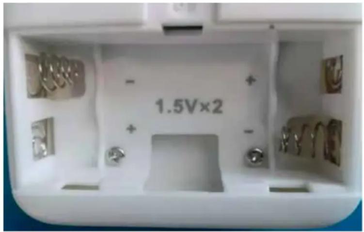
- Remove the battery cover on the back of the Remote Control
- Insert new batteries making sure that the (+) and (-) of battery are installed correctly.
- Reattach the cover by sliding it back into position.
NOTE!
- When replacing batteries, do not use old batteries or a different type battery. This may cause the remote controller to malfunction.
- If you do not use the remote controller for several weeks remove the batteries. Otherwise battery leakage may damage the remote controller.
- The average battery life under normal use is about 6 months.
- Replace the batteries when there is no answering from the unit
- Never mix new and old batteries. Never use different battery types (e.g. alkaline and manganese dioxide) simultaneously.
• Non-rechargeable batteries are not to be recharged - Batteries are to be inserted with the correct polarity
- Exhausted batteries are to be removed from the appliance and safely disposed of
- If the appliance is to be stored unused for a long period, the batteries should be removed
- The supply terminals are not to be short-circuited
APP CONTROL CONNECTION
- First download the app for free from the App Store or Google Play or scan the barcode below.
- Open the app to create your account. The account can be registered through E-mail or Mobile phone. If you already have the account number, just log in with your username and password.


Google Play Apple store
- Set up a WIFI connection. (EZ Mode or AP Mode)
EZ Mode
a. Turn on Wi-Fi on phone settings.
b. Tap "Add device".(Make sure the fan is powered on and there is a red light blinking fast in the center of the ceiling fan lampshade.)
c. Tap "Qlima smart ceiling fan" button under "Air circulation" menu. Tap "Next".(The default pairing mode is EZ Mode for WIFI connection)
d. Select your home WIFI and enter password, tap "Confirm".
e. Wait for the connection to be completed, will enter the main control UI.
If you are unable to set up a WIFI connection via EZ Mode, try AP Mode and follow the below steps.
AP Mode
a. Press and hold

button for 5 seconds.
b. Tap "Add device".
(Make sure the fan is powered on and there is a red light blinking slowly in the center of the ceiling fan lampshade.)
c. Tap "Qlima smart ceiling fan" button under "Air circulation" menu.
d. Tap "Net Pairing Mode", select "AP Mode". Tap "Next".
e. Select your home WIFI and enter password, tap "Confirm".
f. Connect to "Smart life" WIFI signal.
g. Reopen the APP.
h. Wait for the connection to be completed, will enter the main control UI.
- The app will walk you through the main screen and show you how to create schedules, change fan speeds, dim the light, switch between Summer/Winter mode, invite users, create groups and much more. Refer to app instructions for more details. If necessary, you can reconnect the device according to the above steps.
FOR ADAPTER
INPUT:100-240 Va.c. 1.5A 50/60Hz OUTPUT: 24.0Vd.c 3.0A 72.0W TA:10\~40°C TC:80°C Ip20
CAUTION!
- Non-inherently short-circuit proof transformer with non-self-resetting or non-replaceable, protective device and non-replaceable intentional weak parts shall have an information explaining the protective devices, cannot be reset or replaced after a short-circuit or an overload;
- For associated transformers and IP00 transformers, an informative note shall indicate that a 10 % over or under voltage may appear in the supply and the rated output of the transformer shall be selected accordingly;
- The external flexible cable or cord of this transformer cannot be replaced; if the cord is damaged, the transformer shall be scrapped.
 | Product complies with the European Safety Regulations |
 | For indoor use only |
 | SMPS incorporating a short-circuit-proof isolating transformer(inherently or non-inherently) |
 | SMPS(switch mode power supply unit) |
CARE AND CLEANING
- Check the support connections, brackets, and airfoil attachments twice a year. Make sure they are secure. Because of the fan's natural movement, some connections may become loose over time. It is not necessary to remove the fan from the ceiling.
- Clean your fan periodically. Use only a soft brush or lint-free cloth to avoid scratching the finish. The plating is sealed with a lacquer to minimize discoloration or tarnishing.
- (Optional) Apply a light coat of furniture polish to the wood blades.
- (Optional) Cover small scratches with a light application of shoe polish.
- That the replacement of parts of the safety suspension system device shall be performed by the manufacturer, its service agent or suitably qualified persons.
- "The light source contained in this luminaire shall only be replaced by the manufacturer or his service agent or a similar qualified person."
Do not:
- Use water when cleaning. Water could damage the motor, or the wood, or possibly cause an electrical shock.
- Apply oil to your fan or motor. The motor has permanently-lubricated sealed ball bearings.
Note: Power off the fan before product maintenance or cleaning the fan.
WARNING: Changes or modifications to this unit not expressly approved by the party responsible for compliance could void the user's authority to operate the equipment.
TROUBLESHOOTING
Your fan may occasionally jerk forward and backward upon start up. This is normal and does not affect fan operation.
Try these troubleshooting steps before contacting Customer Service.
| Issue Solution | |
| The fan will not start. | 1. Make sure the fan is receiving power.2. Check your circuit breaker or fuse panel and wall switch for functionality.3. Make sure the fan is properly wired and grounded. Check all connections for any damaged, broken, or frayed wires.4. Make sure the plastic film in the remote's battery tray has been removed.5. Remote control must be paired within 10mins of connecting ceiling fan to power source.6. Check to make sure remote control is correctly paired.7. Any wires connecting ceiling fan to power source must be in ON position.8. Try to search the WIFI signal on your phone settings and connect with the app, check to see if the app is able to find the fan.9. If you have paired the remote or the app and the fan still does not start, then try to reset the fan: To reset the fan, cut the power for 10 minutes, then turn the power on and press the pairing button on the remote for 5 seconds until “beep”, then pair the app again to reconnect. |
| The fan wobbles and noisy | 1. Blade screws with the plastic round part against the motor or not.2. Check all the pin wire connect against the moving part.3. Check the down fan cup hit the motor.4. The light kit slanting.5. Check the down rod slanting or not.6. Make sure the colour sticker on the motor and blades match each other.7. Turn off the fan then make the fan running by hand and listen still have noise or not.8. Take out the middle black cover on the light kit and check the middle big nut loose or not.9. When the fan running, touch the light kit by hand, try to make the light kit stable.10. Check the downrod and pivot ball hanging on the bracket if it is seated correctly and in the retention slot.11. Check all mounting points and bracket to see if there are any screws loose.12. The ceiling beam must meet the tensile test strength of 30KG for installation.13. Make sure the airfoils or brackets have not been bent or deformed. |
| LED OFF | 1. Make sure LED wires connect with the controller.2. Make sure the whole fan is powered.3. Make sure the remote control code is matching. |
| Unable to pair remote and app | 1. Check if the wires are connected in the right position or not.2. Check the batteries on the remote.3. Disconnect the power for 10 minutes, then reconnect the power and pair the remote with the fan again within 5 seconds. Also try to pair the app again to reconnect.4. The WIFI must be 2.4Ghz, incompatible with 5Ghz WIFI. |
| Try these troubleshooting steps before contacting Customer Service. For additional operation, maintenance, and troubleshooting information, please contact our service center directly. | |
GUARANTEE CONDITIONS
The appliance is supplied with a 24-month guarantee, commencing on the date of purchase. All material and manufacturing defects will be repaired or replaced free of charge within this period. The following rules apply:
- We expressly refuse all further damage claims, including claims for collateral and/or consequential damage.
- Repairs to or replacement of components within the guarantee period will not result in an extension of the guarantee.
- The guarantee is invalidated if any modifications have been made, non-genuine parts are fitted or repairs are carried out by third parties.
- Components subject to normal wear, are not covered by the guarantee.
- The guarantee is valid only when you present the original, dated purchase invoice and if no modifications have been made to it.
- The guarantee is invalid for damage caused by neglect and/or by actions that deviate from those in this instruction booklet.
- Transportation costs and the risks involved during the transportation of the appliance or components of the appliance shall always be for the account of the purchaser
- Damage caused by not using suitable spare parts is not covered by the guarantee.
To prevent unnecessary expense, we recommend that you always first carefully consult the instructions for use. Take the appliance to your dealer for repairs if these instructions do not provide a solution.
www.qlima.com
ENVIRONMENTAL PROTECTION
Never dispose of non-biodegradable products in the environment, but dispose of them in accordance with current national legislation.
Do not dispose of electrical appliances as unsorted municipal waste, use separate collection facilities.
Contact your local government for information regarding the collection systems available.
If electrical appliances are disposed of in landfills or dumps, hazardous substances can leak into the groundwater and get into the food chain, damaging your health and well-being. When replacing old appliances with new once, the retailer is legally obligated to take back your old appliance for disposal at least for free of charge.
Egregio signore, gentile signora,
(Fig. 1)
STRUMENTI E MATERIALE RICHIESTI
natural_image
Two line drawings of pliers and a screwdriver (no text or symbols)natural_image
Diagram of a propeller assembly with internal components and a magnified view showing internal structure (no text or labels)(Fig. 6)
(Fig. 7) (Fig. 8)
MONTAGGIO
APPENDERE IL VENTILATORE
natural_image
Diagram of a ceiling fan assembly with a close-up inset showing internal components (no text or symbols)(Fig. 18)
(Fig. 22)
ISTRUZIONI D'USO DEL TELECOMANDO
16
⑰
18
19
20
21
natural_image
Diagram of a propeller assembly with internal components and a magnified view showing internal structure (no text or labels)(Afb. 6)
(Afb. 7) (Afb. 8)
MONTAGE
DE VENTILATOR OPHANGEN
natural_image
Diagram of a mechanical assembly with a component and a magnified inset showing a close-up of the component (no text or symbols present)(Afb. 18)
(Afb. 22)
Distributed in Europe by PVG Holding B.V.
Benötigen Sie weitere Informationen oder treten Probleme auf, besuchen Sie bitte unsere Website www.qlima.com, oder setzen Sie sich mit unserem Kundendienst in Verbindung (Telefonnummer auf www.qlima.com).
For alle yderligere oplysninger eller ved eventuelle problemer med apparatet hervises til www.qlima.com eller det lokale Kundecenter (telefonnumre findes i www.qlima.com).
ES Si necesita información o si tiene algún problema, visite nuestra página Web www.qlima.com, o póngase en contacto con el servicio cliente (hallará el número de teléfono en www.qlima.com).
F Si vous souhaitez obtenir des informations supplémentaires ou si vous rencontrez un problème, rendez-vous sur notre site Web (www.qlima.com) ou contactez notre service client (vous trouverez l'adresse et numéro de téléphone sur www.qlima.com).
FHN Jos haluat huoltoapua, lisätietoja tai laitteen kanssa tulee ongelmia, tutustu verkkosivustoon osoitteessa www.qlima.com tai kysy neuvoa PVG kuluttajapalvelukeskuksesta (www.qlima.com).
(6) If you need information or if you have a problem, please visit the our website (www.qlima.com) or contact our sales support (you find its phone number on www.qlima.com)
① Per informazioni e in caso di problemi, visitate il sito Web www.qlima.com oppure contattate il Centro Assistenza Clienti (per conoscere il numero di telefono, consultate www.qlima.com).
Hvis du trenger informasjon, eller hvis du har et problem med produktet, kan du gå til nettsidene www.qlima.com. Alternativt kan du kontakte med PVG' forbrukertjeneste (telefonnummeret i www.qlima.com).
Als u informatie nodig hebt of als u een probleem hebt, bezoek dan de onze website (www.qlima.com) of neem contact op met de afdeling sales support (adres en telefoon op www.qlima.com).
Se necessitar de informações ou se tiver problemas, visite o Web site www.qlima.com ou contacte o Centro de Assistência (número de telefone o www.qlima.com)
FL W przypadku problemów i w celu uzyskania szczegółowych informacji odwiedź stronę internetową Qlima dostępną pod adresem www.qlima.com lub skontaktuj się z Centrum kontaktów Qlima (www.qlima.com)
Om du behöver service eller information eller har problem med apparaten kan du besöka www.qlima.com eller kontakta Qlima kundtjänst (du hittar telefonnumret på www.qlima.com).
Slo Če želite dodatne informacije, obiščite spletno mesto podjetja na naslovu www.qlima.com ali pokličite na telefonsko (www.qlima.com).
TR Daha fazla bilgiye ihtiyaç duyarsanız veya bir sorunla karşılaşırsanız, www.qlima.com adresindeki Qlima Internet sitesini ziyaret edin veya ülkenizde bulunan Qlima müşteri merkeziyle iletişim kurun (telefon numarasını: www.qlima.com).

- AUFBAU
- FLÜGEL INSTALLIEREN
- MONTAGE
- INSTALLEZ UN ABAT-JOUR
- ASSEMBLAGE
- FIXATION DU VENTILATEUR
- INSTRUCTIONS D'UTILISATION DE LA TÉLÉCOMMANDE :
- SYNCHRONISATION DE LA TÉLÉCOMMANDE AVEC VOTRE VENTILATEUR
- CONDITIONS DE GARANTIE
- IMPORTANT COMPONENTS
- DIRECTIONS FOR USE (GB)
- SAFETY PRECAUTION:
- Important: please read before installation:
- BEFORE YOU START
- INSTALLATION:
- INSTALL AIRFOILS
- INSTALL LAMPSHADE
- ATTACH DOWNROD
- ASSEMBLY
- HANGING THE FAN
- If you have an angled or vaulted ceiling: (Fig 17)
- HANGING CEILING FAN & INSTALLING POWER ADAPTER & WIRING THE FAN:
- RAISE CANOPY
- REMOTE CONTROL OPERATING INSTRUCTIONS
- PAIRING THE REMOTE CONTROL TO YOUR FAN
- REMOTE CONTROL BUTTON DEFINITIONS
- Install / Replace Batteries
- NOTE!
- APP CONTROL CONNECTION
- FOR ADAPTER
- CAUTION!
- CARE AND CLEANING
- Do not:
- TROUBLESHOOTING
- GUARANTEE CONDITIONS
- ENVIRONMENTAL PROTECTION
- MONTAGGIO
- APPENDERE IL VENTILATORE
- ISTRUZIONI D'USO DEL TELECOMANDO
- DE VENTILATOR OPHANGEN
- Distributed in Europe by PVG Holding B.V.
Brand : QLIMA
Model : FC 260
Category : Fan