
Bilge IC - Pump Whale - Free user manual and instructions
Find the device manual for free Bilge IC Whale in PDF.


| Product type | Automatic bilge pump with intelligent electronic control IC |
| Brand | Whale |
| Model | Bilge IC (Gulper IC / Strainer IC) |
| Supply voltage | 12 V DC or 24 V DC (depending on model) |
| Voltage range | 10-13.6 V DC (12V) / 20-27.2 V DC (24V) |
| Power consumption | 7.5-8 A (12V) / 3.25-4 A (24V) depending on height |
| Recommended fuse | 10 A (12V) / 5 A (24V) |
| Minimum wire gauge | 1.5 mm² (16 AWG) |
| Weight | 2.6 kg |
| Materials | Head: glass fiber reinforced polypropylene; valves/diaphragm: Santoprene®; motor housing: lacquered steel; gear: Delrin®; screws: stainless steel |
| Max flow rate | 19 L/min (19mm, suction height 0m, discharge height 1m) |
| Max suction height | 3 m |
| Max discharge height | 3 m |
| Max suction + discharge height | 4 m |
| Hose connections | 19 mm or 25 mm (Gulper IC); 19 mm (Strainer IC) |
| Cable length supplied | 2 m or 4 m depending on model |
| Electrical connector | Deutsch® pre-wired |
| IC functions | Intelligent sensor, soft start/stop, timeout 1 s (on) / 45 s (off after detection) |
| Protection | Reverse polarity protection, inline fuse |
| Maintenance | Regular cleaning of Strainer IC; maintenance kit AK2050 (pump head) |
| Applications | Main bilge pump (boats ≤12 m per ISO15083) or secondary |
| Warranty | 2 years |
| Repairability | Rear part not dismountable; head and seals replaceable (kit AK2050) |
Frequently Asked Questions - Bilge IC Whale
User questions about Bilge IC Whale
0 question about this device. Answer the ones you know or ask your own.
Ask a new question about this device
Download the instructions for your Pump in PDF format for free! Find your manual Bilge IC - Whale and take your electronic device back in hand. On this page are published all the documents necessary for the use of your device. Bilge IC by Whale.
USER MANUAL Bilge IC Whale
INSTALLATION AND OPERATION MANUAL
Whale® Bilge IC Waste Pump Range

| Model Number Description | |
| BP2082B Gulper IC - 12 V d.c. | |
| BP2084B Gulper IC - 24 V d.c. | |
| SI8284 | Retail Bilge IC - Remote Mounted Bilge Kit 12 V d.c. |
| SI8484 | Retail Bilge IC - Remote Mounted Bilge Kit 24 V d.c. |
| SI8222B | Bulk Strainer IC and Gulper IC - 12 V d.c with 2m (6ft) cable |
| SI8224B | Bulk Strainer IC and Gulper IC - 12 V d.c with 4m (12ft) cable |
| SI8422B | Bulk Strainer IC and Gulper IC - 24 V d.c with 2m (6ft) cable |
| SI8424B | Bulk Strainer IC and Gulper IC - 24 V d.c with 4m (12ft) cable |
CONTENTS
INSTALLATION AND OPERATION MANUAL Whale® Bilge IC Waste Pump Range
ENG
| Model Number Description | |
| BP2082B Gulper | IC - 12 V d.c. |
| BP2084B Gulper | IC - 24 V d.c. |
| SI8284 Retail Bilge | IC - Remote Mounted Bilge Kit 12 V d.c. |
| SI8484 Retail Bilge | IC - Remote Mounted Bilge Kit 24 V d.c. |
| SI8222B | Bulk Strainer IC and Gulper® IC - 12 V d.c with 2m (6ft) cable |
| SI8224B | Bulk Strainer IC and Gulper® IC - 12 V d.c with 4m (12ft) cable |
| SI8422B | Bulk Strainer IC and Gulper® IC - 24 V d.c with 2m (6ft) cable |
| SI8424B | Bulk Strainer IC and Gulper® IC - 24 V d.c with 4m (12ft) cable |
INSTALLATION & USER INSTRUCTIONS
Thank you for purchasing this Whale® product.
For over 70 years, Whale® has led the way in the design and manufacture of freshwater and waste systems including: pumps, plumbing, faucets and showers for low voltage applications. The company and its products have built a reputation for quality, reliability and innovation backed up by excellent customer service. For information on our full range of products visit www.whalepumps.com
1. TYPICAL INSTALLATION
This Gulper® IC is a high capacity waste pump with intelligent control electronics inside designed to be installed in recreational marine vessels as a remote mounted bilge pump - Suitable as a primary bilge pump for boats up to 12 metres / 39.4 ft (designed to ISO15083), or as a secondary bilge pump on any vessel.
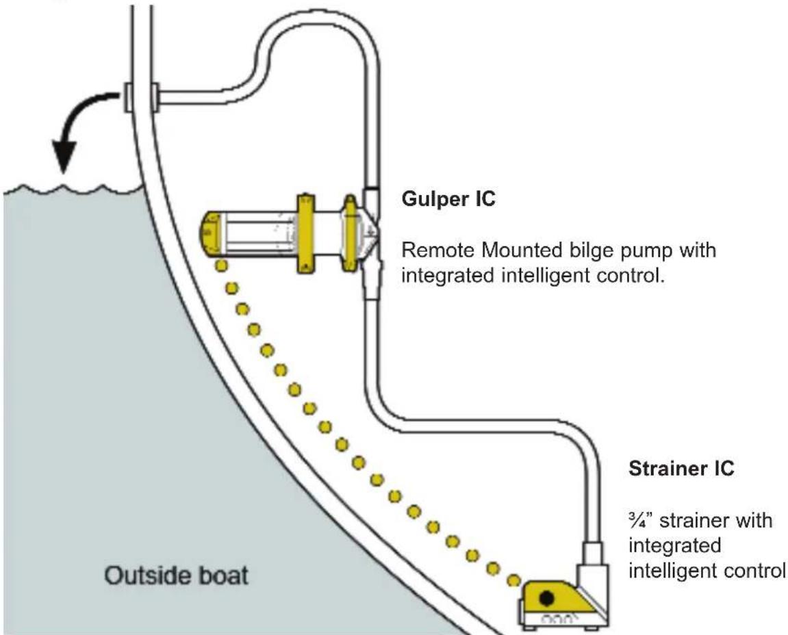
Fig 1. Typical Installation Gulper® IC as a Remote Mounted Bilge Pump
- SPECIFICATION
| Model Bilge IC Bilge Water Kit | ||||||||
| Product Code BP2082B SI8284 | SI8222B | SI8224B | BP2084B | SI8484 S | 8422B S | 8424B | ||
| Cable Length / | 4m(12ft) | 2m(6ft) | 4m(12ft) | / | 4m(12ft) | 2m(6ft) | 4m(12ft) | |
| Voltage | 12V d.c. 24V d.c. | |||||||
| Voltage Range 10 v d.c. to 13.6 V d.c. 21.6 V d.c. to 27.2 V d.c | ||||||||
| Current Profile Soft start / soft stop | ||||||||
| Recommended Fuse Size | 10 Amp Automotive 5 Amp Automotive | |||||||
| Minimum Wire Size | 1.5mm2 (16 AWG) | |||||||
| Weight | 2.6 kg (5.7 lbs) | |||||||
| Materials | Pump head - Glass filled Nylon. Valves and Diaphragm - Santoprene®Pump Body - Aluminium. Gear Wheel - Delrin®Fasteners - Stainless Steel | |||||||
| Service Kits / Accessories | AK2050 - Replacement Gulper® Pump HeadAK2086B - Deutsch Connector Extension Cable 6m (18ft) | |||||||
| Hose Connections | Gulper® IC - Barbed connections - either 19mm ( 3/4 ) or 25mm (1")Strainer IC - 19mm ( 3/4 ) port | |||||||
| Port Orientation for Strainer IC | Horizontal (easily changed to vertical / side) | |||||||
| Maximum Suction Lift (Vertical) | 3m (10 ft) | |||||||
| Maximum Discharge Head (Vertical) | 3m (10 ft) | |||||||
| Maximum Discharge Head and Suction Lift Combined (vertical vent) | 4m (13.5 ft) | |||||||
| Operational Time Delays | 1 second on delay / 45 second off delay | |||||||
| Current Draw On Standby | Low power 0.01 Amps supply | |||||||
PERFORMANCE DATA
| Suction Lift | 0m / 0ft | 0m / 0ft | 1m / 3ft | 1m / 3ft |
| Discharge Head | 1m / 3ft | 1m / 3ft | 1m / 3ft | 1m / 3ft |
| Hose Size | 19mm / 3/4" | 25mm/ 1" | 19mm / 3/4" | 25mm/ 1" |
| Flow Rate per min | 19 ltrs(5 US gals) | 17.5 ltrs(4.6 US gals) | 17.5 ltrs(4.6 US gals) | 15.5 ltrs(4.1 US gals) |
| Flow Rate per hour | 1140 ltrs(300 US gals) | 1050 ltrs(276 US gals) | 1038 ltrs(270 US gals) | 930 Ltrs(246 US gals) |
| Current Draw (12 V d.c.) | 7.5 amps | 8 amps | 7.5 amps | 8 amps |
| Current Draw (24 V d.c.) | 3.25 amps | 4 amps | 3.25 amps | 4 amps |
Note - Output capacity depends on installation and operating conditions.
Whale's policy is one of continuous improvement and we reserve the right to change specifications without prior notice. 3
3. LIST OF CONTENTS AND LIST OF DIAGRAMS
- TYPICAL INSTALLATION 12. PLUMBING
- SPECIFICATION 13. INSTRUCTIONS FOR USE
- CONTENTS AND DIAGRAMS 14. MAINTENANCE
- PRINCIPLES OF OPERATION 15. HELPFUL HINTS
- TO THE USER 16. TROUBLE SHOOTING
- TO THE FITTER 17. WINTERIZING
- APPLICATION 18. SERVICE SUPPORT DETAILS
- WARNINGS
- PARTS LIST 20. WARRANTY STATEMENT
-
INSTALLATION
-
OPTIONAL EXTRAS 21. EU DECLARATION OF CONFORMITY, APPROVALS
19.
PA
LIST OF DIAGRAMS:
| Fig 1 | Gulper® IC - Typical Installation - Remote Mounting Bilge Pump For Use With Whale Strainer IC |
| Fig 2 | Pump Orientation |
| Fig 3 | Gulper® IC Installation |
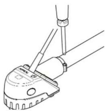
| Fig 4 | Install P Clamp |
| Fig 5 | Strainer IC Connection |
| Fig 6 | Strainer IC Connection |
| Fig 7 | Wiring Gulper® IC To Strainer IC |
| Fig 8 | Connecting Switching Cable Through Bulkhead |
| Fig 9 | Connect Deutsch® Connectors |
| Fig 10 | Securing Pipework |
| Fig 11 | Strainer IC Operation Test |
| Fig 12 | For Cleaning - Detach Top Cover Of Strainer IC |
| Fig 13 | For Cleaning - Unscrew Valve Housing |
4. PRINCIPALS OF OPERATION
IC - Intelligent Control Technology
At the heart of every Whale® IC product lies innovative electronic control circuitry built in. This enables IC sensor accessories to communicate directly with IC pumps to control their performance.
These accessories send signals to built-in intelligent software which then control the pumps to react as required.
Gulper® IC
The Gulper® IC fully automatic self-priming pump is designed as a remote mounting bilge pump. Output capacity depends on installation and operating conditions.
Remote Mounted Bilge Application
Save time and money by reducing four separate components to one pre-wired system. Remote mounting automatic Gulper® IC receives signals from Strainer IC and switches on and off automatically (See Fig 1). Suitable for a primary bilge pump for boats smaller than 12 metres/39.4 ft (designed to ISO15083), or as a secondary bilge pump on any recreational marine vessel.
5. TO THE USER
Read the following instructions carefully.
6. TO THE FITTER
Check that the product is suitable for the intended application, follow these installation instructions and ensure all relevant personnel read the points listed below. Also ensure that these operating instructions are passed on to the end user.
7. APPLICATION
Gulper® IC is designed for installation in recreational marine vessels only and operated on 12 or 24 V d.c. electrical supply only. If it is intended for use for any other purpose or with any other liquid, it is the user's responsibility to ensure that the pump is suitable for the intended use and, in particular, that the materials are fully compatible with the liquids to be used. The Whale Gulper® IC pump is not recommended for domestic applications.
8. WARNINGS
- This pump must not be mounted below the water line when connected to an intake or outlet unless the system has a vented loop (see Fig 1).
- Not suitable for pumping flammable liquids, diesel, chemicals etc. Suitable for bilge water only.
- NOTE: Bilge pump capacities may not be sufficient to prevent flooding from rapid accumulation of water due to storms, rough weather and/or rapid leaks created by hull damage and or unsafe navigational conditions.
- With all applications, it is important that a system of safe working practice is applied to installation, use and maintenance. Ensure the electric supply is turned off and waste water system is drained before installation. In order to securely fasten the unit, ensure that the mounting surface is a minimum thickness of 19mm ( 3/4 ") (when fitted with the screws supplied).
- NOTE Do not screw directly to the hull - must be mounted on a bulkhead or on an additional board.
- NOTE - DO NOT unscrew the rear section, as interference with the internal electrics will render the pump unfit for use. - this is a non-serviceable part of the pump.
- WARNING: Fire hazard. Wiring must comply with applicable electrical standards and include a properly rated fuse or circuit breaker (See section 11vi.) Improper wiring can cause a fire resulting in injury or death. Switch off the power while making connections. Suggested wiring information is given as a guide only. For full information, refer to the USCG,ABYC and ISO regulations for marine applications and wiring gauges, connectors and fuse protection.
Contact Whale® Support team for further technical advice +44 (0)28 9127 0531 or email: info@whalepumps.com
9. PARTS LIST
Qty 1 Gulper® IC bilge pump Qty 1 Strainer IC
Qty 3 No.8 self tappers and washers Qty 1 Inline fuse assembly
10. OPTIONAL EXTRAS
AK2050 - Service kit - Replacement head for all Gulper® pumps
AK2086B - Deutsch® Connector Extension Cable 6m (18ft)
11. INSTALLATION
NOTE: Incorrect installation will invalidate warranty.
Preparation - Always disconnect power sources before installing.
11.i Location
- Choose a position to mount the pump that is dry and away from standing water and is free from obstacles.
- Mount in a position with the shortest possible pipe run lengths.
11.ii Mounting Instructions - Gulper® IC
- Gulper® IC can be mounted on a horizontal or vertical surface.

- When mounted vertically ensure that the pump head is below the motor body (see Fig 2).
NOTE - It is recommended that the outlet is mounted above the water line and anti-syphon loops are fitted where applicable - see typical installation (Fig 1).
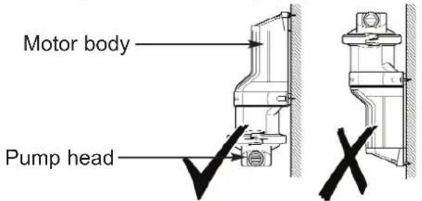
Fig 2. Pump Orientation
- When mounting, position the pump on surface and work out the best angles for the hose (to prevent kinking) and mark the 3 hole positions using the pump feet.
- NOTE: The pump head may be rotated to suit the hose connections. Loosen the screw, adjust and ensure diaphragm remains in place. Reposition the head to the required position (Fig 3) and tighten the screw.
- Drill pilot holes of 3mm ( 1/8 ).
- Use the three No.8 self tappers and washers (included) to secure the pump.
NOTE: Do not drill through hull, ensure that pump is mounted to additional board or bulkhead.
- Use 19mm ( 3/4 ") or 25mm (1") smooth bore reinforced hose to connect to the pump with hose clips.
NOTE: Barbed connections mean no need to cut inlets or outlets to size.
NOTE: Ensure tight connections, but do not over-tighten clamp rings/screws/hose clips.
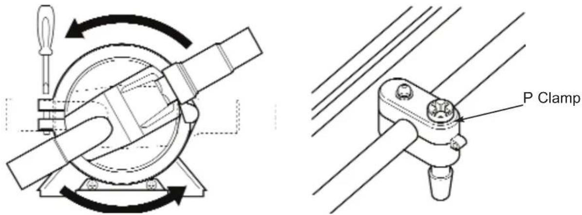
Fig 3. Gulper® Installation Fig 4. Fit P Clamp
- Screw P clamp to bulkhead ensuring it is located Approx. 100 mm (4") from rear housing (Fig 4). NOTE: In order to securely fasten the unit, ensure that the p clamp mounting surface is at least 19mm ( 3/4 ") minimum thickness.
11.iii Mounting Instructions - Strainer IC
- Mount in a position with the shortest pipe run lengths.
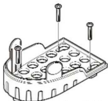
Fig 5. Connect Strainer IC to Bulkhead
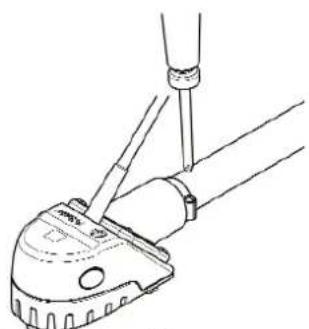
Fig 6. Attaching Jubilee Clips
- Drill pilot holes. NOTE: do not drill through hull, ensure that strainer is mounted to additional board or bulkhead (Fig 5).
- Use 19mm ( 3/4 ) smooth bore reinforced hose to connect to the strainer with hose clips (Fig 6).
- Secure cable by screwing 'P' clamp to bulkhead ensuring it is located approx. 100 mm (4") from strainer outlet (Fig 4).
11.iv Electrical Wiring
- For installation use pre-wired Deutsch® connectors (attached).
- If you are not familiar with applicable electrical standards, ensure that the unit is installed by a qualified electrician/ technician.
WARNING: Fire hazard. Wiring must comply with applicable electrical standards and include a properly rated fuse or circuit breaker. Improper wiring can cause a fire resulting in injury or death.
NOTE Switch off the power prior to making connections. Suggested wiring information is given as a guide only. For full information, refer to the USCG, ABYC and ISO regulations for marine applications and wiring gauges, connectors and fuse protection.
Connect Power Cables
The polarity is indicated by coloured cable (Positive = red, Negative = black).
The white wire can be connected to a running light to indicate when the system is in use and / or as a manual override switch.
NOTE The pump is protected against reverse polarity connection (the inline fuse will blow).
NOTE: Undersized wire in the circuit before the pump will reduce voltage when the pump is under load, thus giving poor performance and potential motor failure.
- Ensure all power cables installed are at least the minimum wire size - 1.5mm 2 (16AWG)
- To control the pump, an isolator switch must be fitted between the positive live terminal on the battery and the positive lead on the pump (See section 11 v).
WARNING Ensure that there are no loops of electrical cable that could be a hazard.
11.v Wiring Diagrams
![graph TD A["+ Battery"] --> B["FUSE"] B --> C["ISOLATOR SWITCH ON/OFF"] C --> D["ON/OFF"] D --> E["OVERRIDE SWITCH"] E --> F["ON"] F --> G["WHITE"] G --> H["P"] H --> I["GULPER IC"] I --> J["DEUTSCH CONNECTORS"] J --> K["A"] L["BATTERY"] --> M["RUNNING LIGHT"] M --> H N["BLACK"] --> H O["STRainer IC…](/content/2026/04/692168/images/97f56308a72cee1e3c9415fadd5c6490eaa7b9e34ec22d3a6e2bdbd6fdf381aa.jpg)
Fig 7. Wiring Gulper® IC to Whale Strainer IC
11.vi. Fitting the Fuse
Fuse rating for BP2082B (12 V d.c.) pumps 10 Amp automotive.
Fuse rating for BP2084B (24 V d.c.) pumps 5 Amp automotive.
The in-line fuse assembly supplied must be fitted to the positive side of the pump (see Fig 7).
Purpose of Fuse: The purpose of this fuse is to protect the pump from serious damage in the event of system blockages, therefore please ensure all valves are fully open before operating the pump.
If the fuse blows:
a) Check that all system valves/stop cocks are open
b) Check that the inlet and outlet ports are not blocked
c) Check that the rest of the system is not blocked
d) Check for reverse polarity connection
11.vii Connect Switching Cable
If switching cable must be fitted through bulkhead, ensure a minimum hole diameter 25mm (1") is drilled.
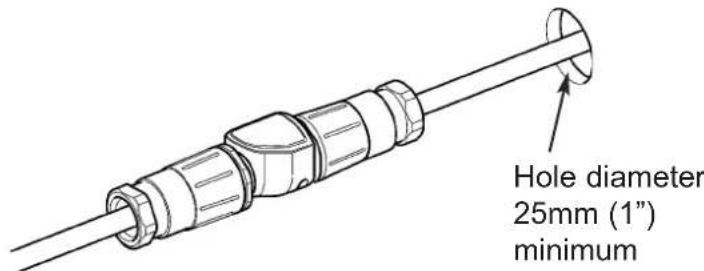
Fig 8. Connecting Switching Cable Through Bulkhead
11.viii Connecting Gulper IC to Strainer IC (See Fig 1)
Connect the pre-wired Deutsch connectors on Gulper® IC and Whale Strainer IC (Fig 9).
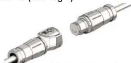
Fig 9. Connect Deutsch Connectors
12. PLUMBING
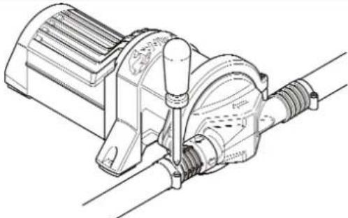
Fig 10. Secure Pipework
Use 19mm (3/4") or 25mm (1") smooth bore reinforced pipework to connect to the pump.
Secure the pipework on inlet and outlet with worm drive hose clip (Fig 10).
13. INSTRUCTIONS FOR USE
Ensure that pump installation is thoroughly tested before first use. NOTE - These are all automatic or semi-automatic applications - ensure that isolator switch is turned on.
Bilge application
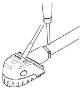
Gulper® IC with Strainer IC - Place finger over sensor area to check pump is activated, remove finger and wait for the pump to stop (45 seconds).

Fig 11. Testing Strainer IC
14. MAINTENANCE
This Whale Gulper® IC is designed to only require minimal maintenance.
WARNING: Before servicing pump, turn off pump and drain water from system.
Annual checks
- Whale advise that the boat's plumbing system is checked annually for leaks and obstructions. Also a pump electrics check is advisable.
- Before inspecting or replacing the diaphragm, disconnect the electrical supply.
Optimal performance
- Ensure this product is clear of debris.
If the pump is not operating as expected:-
- Loosen the hose clips to release the pump from plumbing.
- Unscrew the Ezi-clamp clamping ring to release the pump head (Fig 3). This will release the pump head, and allow easy access to the valves & diaphragm.
- The diaphragm and valves should be checked for any excessive wear, damage or cracks, and should be replaced if necessary (service kit AK2050 - replacement pump head).
Cleaning
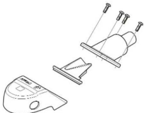
Bilge IC should be wiped clean regularly to maintain optimal performance and ensure no clogging occurs. See Fig 12 and Fig 13 for cleaning Strainer IC. WARNING: Do not use abrasive cleaners.
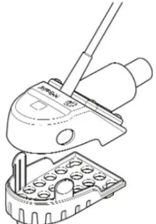
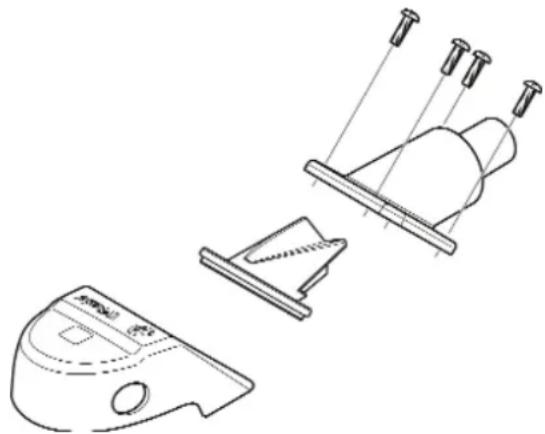
Fig 12. For Cleaning - Detach Top Cover Fig 13. For Cleaning - Unscrew of Strainer IC Valve Housing
15. HELPFUL HINTS
The unique ezi-clamp ring makes installation and maintenance of the pump easier with a retaining screw which means the head can be fitted or replaced easily by one fitter, without the risk of dropping screws.
16. TROUBLESHOOTING
WARNING: DO NOT unscrew the rear section as interference with the internal electrics will render the pump unfit for use - this is a non-serviceable part of the pump.
| PROBLEM POSSIBLE CAUSES POTENTIAL SOLUTION | ||
| Gulper IC fails to operate | The Strainer IC may need cleaned.Blockage in valve housing | Unclip the top cover of the Strainer IC, clean and inspect for debris (Fig 12). Carefully remove the lid and clean the inside walls, if necessary unscrew the valve housing assembly for further cleaning. |
| Isolator switch not working / not switched on.Pump circuit has no power | Check the isolator switch is on and working.Check electrical connections to ensure pump is receiving power as normal and free from corrosion.Check power supply. | |
| Main power (Isolator switch) supply OFF /not working. Loose wiring connection | Check the isolator switch is on. | |
| Pump circuit has no power | Check electrical connections to ensure pump is receiving power as normal and free from corrosion.Check there is 12/24 volts from the battery. | |
| Fuse blown or loose electrical connection | Check the in-line fuse & ensure all electrical connections are tight and free from corrosion. If fuse has blown, check for reverse polarity, closed valves or seacocks, then for debris in pump head and clean out if necessary (refer to installation section).Replace fuse and run pump. | |
| Failure to prime - Motor operates, but no pump discharge | Debris under flap valves / not seated properly | Turn off electrics and disconnect plumbing check valves for blockages and remove debris (See section 14). |
| Air leak in intake line | Check hose connections are airtight. Open pump head and check valves and diaphragm (see section 14). | |
| Punctured pump diaphragm | Replace the damaged part using service kit - Part number AK2050. | |
| Restricted intake or discharge line | Check all hose connections are airtight, free from blockages, and hose has not collapsed/kinked. | |
| Pump fails to turn off when required | Strainer IC bilge strainer, not working | Check Strainer IC is operating properly (see section 13). |
| Defective/ debris on grey waste float switch | Clear debris/ replace float switch. | |
| Insufficient voltage to the pump | Check power supply to pump. | |
| Override switch activated Turn | off override switch. | |
| Low flow | Air leak at pump intake Check | the hose connections are airtight. |
| Debris inside pump and plumbing | Turn off electrics and disconnect plumbing, check for blockages and remove (See section 14). | |
| Punctured pump diaphragm | Replace the damaged part using service kit - Part number AK2050. | |
| Defective electronic control | Replace pump. If within specified warranty period contact Whale (see contact details). | |
17. WINTERIZING
NOTE: Winterizing - Fully drain system.
Whale® cannot guarantee warranty if the system is not fully drained for winterizing.
18. SERVICE SUPPORT DETAILS
For installation or service advice please contact Whale® customer support:
UK Tel: +44 (0)28 9127 0531 USA Tel: 1 616 897 9241
UK Email: info@whalepumps.com Email USA: usasales@whalepumps.com
19. PATENTS AND TRADEMARKS
Whale® and Gulper ® are registered trademarks to Munster Simms Engineering Limited (also trading as Whale). Whale® Gulper® IC products are protected by the following patent applications:
P92580GB00 P92043GB00
DEUTSCH® is a registered trade name of Deutsch Group. Santoprene® is a registered trade name of Advanced Elastomer Systems, LP, an Exxonmobil Chemical Affiliate Delrin,® Teflon® and Neoprene are registered trade names of Dupont Neumeurs and Co. Monprene® is a registered trade name of Technore Apex.
20. WARRANTY STATEMENT
This Whale® product is covered by 2 year warranty - Please see enclosed document for details of our statement of limited warranty.
21. DECLARATION OF CONFORMITY, STANDARDS, APPROVALS
This product complies with all relevant European directives and standards. Please contact Whale® if further details are required.
EU Declaration no.: EU-MSE005-001 Technical file number: TF-MSE005-001
We the undersigned: Name of manufacturer: Munster Simms Engineering Ltd
Address: Unit 2 Enterprise Road, Bangor, Co. Down, BT197TA
Country: United Kingdom
Declare under our sole responsibility that the following apparatus:
Product description: Gulper Intelligent Control (IC) Kits and accessories
Model name and no.: Bilge IC Pump Kits: SI82XX, SI84XX
Grey Waste Pump Kits: SG8XXX, WM8XXX
IC Accessories: SI25XX, SI34XX, SG19XX, SG34XX,
WM19XX, WM25XX, WM38XX
Brand name: Whale
Is/Are in conformity with the following relevant EU Legislation:
2013/53/EU Recreational Craft Directive
2014/30/EU EMC Directive
2011/65/EU RoHS II Directive
Based on the following harmonized standards:
EN 55014-1:2006 + A2:2011 EMC Emissions
EN 55014-2:1997+ A2:2008 EMC Immunity
EN 28846:1993 + A1:2000 Ignition Protection
EN ISO 8849:2003 Electrically Operated Bilge Pumps
EN ISO 15083: 2003 Small Craft - Bilge Pumping Systems
And the following non-harmonized standards:
And therefore complies with the essential requirements of those directives.
Additional information:
Where applicable this product also conforms to the following standards:
ABYC H-22, 2011 DC Electric Bilge Pumps operating under 50 volts
Name and position of person binding the manufacturer or authorized representative:
Name: Richard Bovill
Function: Engineering Director
Location: Munster Simms Engineering Ltd, 2 Enterprise Road, Northern Ireland, BT19 7TA
Date of Issue: 26.04.16
MANUEL D'INSTALLATION ET DE FONCTIONNEMENT
Fig 2. Orientation de la Pompe
Application a la Cale
2011/65/UE Directive RoHS II
Anschrift: Unit 2 Enterprise Road, Bangor, Co. Down, BT197TA
Name: Richard Bovill
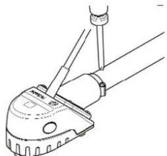
Fig 9. Collegare i Connettori Deutsch
12. ALLACCIAMENTI IDRAULICI
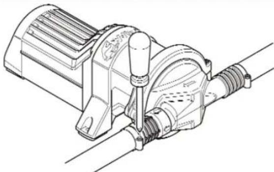
Fig 11. Test del Strainer IC
Indirizzo: Unit 2 Enterprise Road, Bangor, Co. Down, BT197TA
Paese:
Regno
Unito
Sede: Munster Simms Engineering Ltd,
2 Enterprise Road, Bangor, BT19 7TA, Bangor, Irlanda del Nord
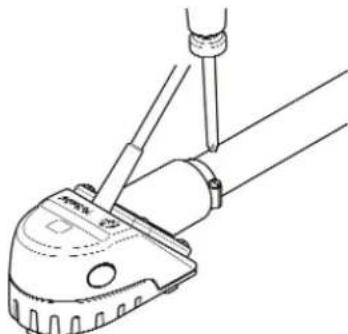
Fig 9. Conectar los Conectores Deutsch®
12. TUBERÍAS

Fig 11. Comprobación del Filtro Strainer IC
14. MANTENIMIENTO
Fig 12. Para Limpieza: Quitar la Tapa Superior del Rejilla Strainer IC
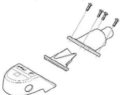
Fig 2. Pump Orientering
Fig 3. Gulper® Installation
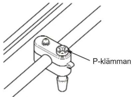
Fig 4. Montera P-klämman
Fig 5. Anslut Strainer IC till skottet
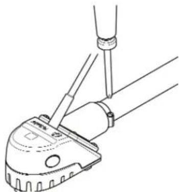
Fig 9. Anslut den Tysk-kontakten
12. RÖRDRAGNING
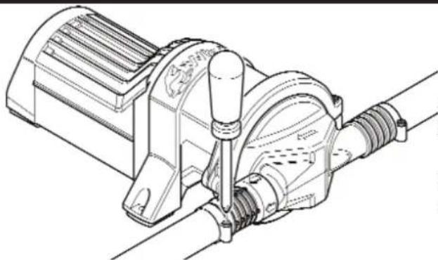
Fig 12. För Rengöring - Demontera Kåpan På Strainer IC
Adress: Unit 2 Enterprise Road, Bangor, Co. Down, BT197TA
Osoite: Unit 2 Enterprise Road, Bangor, Co. Down, BT197TA
Maa: Yhdistynyt
kuningaskunta
©Copyright Whale 2018 - All rights reserved. Reproduction in whole or in part without permission is prohibited. WHALE®, is a registered trademark of Munster Simms Engineering Limited, Bangor, Northern Ireland trading as Whale. Whale's policy is one of continuous improvement and we reserve the right to change specifications without prior notice. Illustrations are for guidance purposes only. Neither the accuracy nor completeness of the information contained in this or any product literature is guaranteed by the Company and may be subject to change at its sole discretion.
Munster Simms Engineering Ltd.
2 Enterprise Road, Bangor, N. Ireland BT19 7TA
Tel: +44 (0)28 9127 0531
Email: info@whalepumps.com
www.whalepumps.com
Whale (The Americas)
Tel: 1 616 897 9241
Email: usasales@whalepumps.com
www.whalepumps.com
Ref: 183.16_v5_1118_sr_db


- INSTALLATION AND OPERATION MANUAL
- CONTENTS
- INSTALLATION AND OPERATION MANUAL WHALE® BILGE IC WASTE PUMP RANGE
- INSTALLATION & USER INSTRUCTIONS
- TYPICAL INSTALLATION
- LIST OF CONTENTS AND LIST OF DIAGRAMS
- PRINCIPALS OF OPERATION
- IC - INTELLIGENT CONTROL TECHNOLOGY
- GULPER® IC
- REMOTE MOUNTED BILGE APPLICATION
- TO THE USER
- TO THE FITTER
- APPLICATION
- WARNINGS
- PARTS LIST
- OPTIONAL EXTRAS
- INSTALLATION
- 11.I LOCATION
- 11.II MOUNTING INSTRUCTIONS - GULPER® IC
- 11.III MOUNTING INSTRUCTIONS - STRAINER IC
- 11.IV ELECTRICAL WIRING
- CONNECT POWER CABLES
- 11.V WIRING DIAGRAMS
- 11.VI. FITTING THE FUSE
- 11.VII CONNECT SWITCHING CABLE
- 11.VIII CONNECTING GULPER IC TO STRAINER IC (SEE FIG 1)
- PLUMBING
- INSTRUCTIONS FOR USE
- BILGE APPLICATION
- MAINTENANCE
- ANNUAL CHECKS
- OPTIMAL PERFORMANCE
- IF THE PUMP IS NOT OPERATING AS EXPECTED
- CLEANING
- HELPFUL HINTS
- TROUBLESHOOTING
- WINTERIZING
- SERVICE SUPPORT DETAILS
- PATENTS AND TRADEMARKS
- WARRANTY STATEMENT
- DECLARATION OF CONFORMITY, STANDARDS, APPROVALS
- MANUEL D'INSTALLATION ET DE FONCTIONNEMENT
- APPLICATION A LA CALE
- ALLACCIAMENTI IDRAULICI
- TUBERÍAS
- MANTENIMIENTO
- RÖRDRAGNING
Brand : Whale
Model : Bilge IC
Category : Pump