
Alysea E - Air Conditioning OLIMPIA SPLENDID - Free user manual and instructions
Find the device manual for free Alysea E OLIMPIA SPLENDID in PDF.

| Brand | Olimpia Splendid |
| Model | Alysea E |
| Product type | Split inverter air conditioner with heat pump |
| Refrigerant | R32 (flammable A2L) |
| Capacity | 9,000 – 12,000 BTU/h |
| Operating modes | Auto, Cool, Dry, Fan only, Heat |
| Main functions | Turbo, Sleep, I Feel, ECO, Gentle Wind, Fresh Air, Self‑clean, Oscillation, Timer, Mute, Child Lock, 8°C Heat |
| Outdoor temperature range (cool) | -15°C to 53°C |
| Outdoor temperature range (heat) | -20°C to 30°C |
| Maximum piping length | 15 m |
| Max. level difference (ID/OD) | 10 m |
| Additional refrigerant charge | 15 g/m beyond 5 m |
| Remote control | Yes, with LCD display and 2 AAA 1.5V batteries (not included) |
| Filters | Standard air filter + 4-layer fresh air filter (replacement recommended every 6 months) |
| Maintenance | Regular filter cleaning; Self‑Clean function available |
| Safety | Automatic circuit breaker required; cut power before maintenance; flammable gas |
| Spare parts / repairability | Only Olimpia Splendid original parts; intervention by certified technician (fluorinated gases) |
| General information | Manual available for download (436 pages); Wi‑Fi compatible (reset via remote control) |
Frequently Asked Questions - Alysea E OLIMPIA SPLENDID
• Press DISPLAY 6 times within 8 seconds,
• Or press ECO 6 times within 8 seconds,
• Or press MODE for more than 3 seconds.
The screen will display 'CF' or 'AP' and the appliance will emit two beeps.
User questions about Alysea E OLIMPIA SPLENDID
0 question about this device. Answer the ones you know or ask your own.
Ask a new question about this device
Download the instructions for your Air Conditioning in PDF format for free! Find your manual Alysea E - OLIMPIA SPLENDID and take your electronic device back in hand. On this page are published all the documents necessary for the use of your device. Alysea E by OLIMPIA SPLENDID.
USER MANUAL Alysea E OLIMPIA SPLENDID
natural_image
Front view of a white cylindrical air conditioner unit with a blue top and digital display (no visible text or symbols)Caution: risk of fire
Tasselli in plastica
natural_image
Line drawing of a smartphone screen with rounded corners and a horizontal scroll (no text or symbols)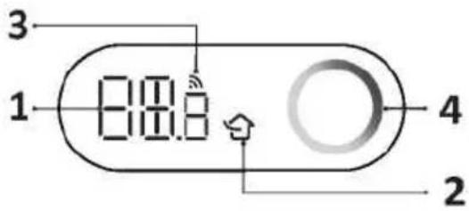

natural_image
Diagram of a battery pack assembly with arrows indicating components (no text or labels)Manicotto a muro (optional)
Esterno
5-10 mm
natural_image
Diagram showing two types of electrical connectors: a threaded connector and a wire-wound plug, with no text or symbols present.INSTALLAZIONE DELL'UNITÀ INTERNA
natural_image
Technical line drawing of a mechanical device interior (no text or symbols)Prese di drenaggio
natural_image
Simple line drawing of a wall-mounted device with a cable attached, no text or symbols present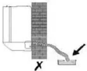
natural_image
Diagram showing a pipe flowing from a brick wall to a water channel, with an arrow indicating direction (no text or symbols)
flowchart
graph LR
    A["Rectangular Block"] --> B["Segmented Rectangle"]
    B --> C["Final Segmented Rectangle"]
natural_image
Technical line drawing of an internal electronic device with a cable extending into it (no text or symbols present)natural_image
Simple line drawing of a mechanical or structural component with no visible text, numbers, or symbols.natural_image
Line drawing of a dual-panel air conditioner unit with fan blades and ventilation slots (no text or symbols)natural_image
Diagram showing airflow from a fan to a commercial air conditioner unit, with no text or symbols present.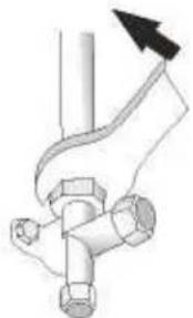
natural_image
Pure mechanical diagram showing a pipe joint with a valve and bolt, no text or symbols presentGENERAL WARNINGS....2
NAME OF PARTS......13
REMOTE CONTROL....15
OPERATION INSTRUCTIONS ......23
INSTALLATION PRECAUTIONS ....24
INDOOR UNIT INSTALLATION....25
OUTDOOR UNIT INSTALLATION....35
TROUBLESHOOTING....41
DISPOSAL
This symbol on the product or its packaging indicates that the appliance cannot be treated as normal domestic trash, but must be handed in at a collection point for recycling electric and electronic appliances.
Your contribution to the correct disposal of this product protects the environment and the health of your fellow men.
Health and the environment are endangered by incorrect disposal.
Further information about the recycling of this product can be obtained from your local town hall, your refuse collection service, or in the store at which you bought the product.
This regulation is valid only in EU member states.
0 - SYMBOLS
The pictograms in the next chapter provide the necessary information for correct, safe use of the machine in a rapid, unmistakable way.
Index
Paragraphs marked with this symbol contain very important information and recommendations, particularly as regards safety. Failure to comply with them may result in:
- danger of injury to the operators
- loss of the warranty
- refusal of liability by the manufacturer.

HAZARD
icates that the appliance uses inflammable refrigerant. If the refrigerant escapes and is exposed to a source of external ignition, there is a fire risk.
als to the personnel that the operation described could cause electrocution if not performed according to the safety rules.
GENERIC DANGER
forms the personnel concerned that if the operation is not carried out in compliance with the safety regulations, it presents the risk of suffering physical damage.
0.1 - GENERAL WARNINGS
WHEN USING ELECTRICAL EQUIPMENT, BASIC SAFETY PRECAUTIONS MUST ALWAYS BE FOLLOWED IN ORDER TO REDUCE RISKS OF FIRE, ELECTRIC SHOCKS
AND INJURY, INCLUDING THE FOLLOWING:
-
This document is restricted in use to the terms of the law and may not be copied or transferred to third parties without the express authorization of the manufacturer, OLIMPIA SPLENDID. Our machines are subject to change and some parts may appear different from the ones shown here, without this affecting the text of the manual in any way.
-
Read this manual carefully before performing any operation (installation, maintenance, use) and follow the instructions contained in each chapter.
-
Make all personnel involved in transport and installation of the machine aware of these instructions.
-
THE MANUFACTURER IS NOT RESPONSIBLE FOR DAMAGES TO PERSONS OR PROPERTY CAUSED BY FAILURE TO FOLLOW THE INSTRUCTIONS IN THIS MANUAL.
-
The manufacturer reserves the right to make any changes it deems advisable to its models, although the essential features described in this manual remain the same.
- The installation and maintenance of air-conditioners like this one may be hazardous as they contain a cooling gas under pressure as well as powered parts. Therefore, the installation, first startup and subsequent maintenance should be carried out exclusively by authorized, qualified personnel.
- Failing to comply with the instructions contained in this manual, and using the unit with temperatures exceeding the permissible temperature range will invalidate the warranty.
- Routine maintenance of the filters and general external cleaning can be done by the user as these operations are not difficult or dangerous.
- During installation and maintenance, respect the precautions indicated in the manual, and on the labels applied inside the units, as well as all the precautions suggested by good sense and by the safety regulations in effect in your country.
- Perform installation and maintenance using equipment that is suitable for inflammable gas.
- Always wear gloves and protective goggles when performing any operations on the refrigerating side of the units.
- Air conditioners must not be installed in places containing inflammable gasses, explosive gasses, or in very humid environments (laundries, greenhouses, etc.), or in places where there are machines that generate very great heat.
- In case of replacement of parts, use only original OLIMPIA SPLENDID parts.

- IMPORTANT!
prevent any risk of electrocution, always disconnect the main circuit breaker before making electric connections or performing any maintenance on the units.
- Lightening, cars in the vicinity and mobile phones can cause malfunctioning. Disconnect the unit electrically for a few seconds and then re-start the air conditioner.
- On rainy days, it is recommended to connect the electric power supply in order to prevent damage caused by lightening.
- If the unit is unused for a long period, or no-one uses the climate-controlled room, it is recommended to disconnect the electric power supply in order to prevent accidents.
- Do not use liquid or corrosive detergents to clean the unit, do not spray water or other liquids onto the unit, since they could damage the plastic components or even cause electric shocks.
- Do not wet the indoor unit and the remote control. circuits or fires may occur.

- In the event of operating anomalies (e.g. strange noise, bad odour, smoke, abnormal temperature rise, electric dispersions, etc.) disconnect the electric power supply immediately. Contact the local dealer.
- Do not let the air conditioner run for a long time when the humidity is very high and a door or a windows is left open.
Moisture may condense and wet or damage furniture.
- Do not plug or unplug the power supply plug during operation. and electric shocks risk.
- Do not touch (operation) the product with wet hands and electric shocks risk.

- Do not place a heater or other appliance near the power cable. Fire and electric shocks risk.
- Make sure water does not enter the electrical parts. Id cause fires, product failure or electric shocks.
-
Do not open the air inlet grid during appliance operation. Risk of injury, electric shock or damage to the product.
-
Do not block the air inlet or outlet; the product could be damaged.
-
Do not insert hands or other object through air inlet or outlet while the product is operated.
The presence of sharp and moving parts could cause injury.
- Do not drink the water drained from the product.
It is not sanitary could cause serious health issues.
-
When there are gas leaks from other units, ventilate the room well before activating the air conditioner.
-
Do not disassemble or modify unit.
-
Ventilate the room well when used together with a stove, etc.
-
Do not use for special purposes.
-
The persons that work or intervene on a cooling circuit, must be in possession of suitable certification, issued by an accredited assessment body. This must attest skill in safely handling refrigerants in compliance with assessment specification acknowledged by sector associations.
-
Do not emit R32 gas into the atmosphere; R32 is a fluorinated greenhouse gas with a Global Warming Potential (GWP) = 675.
-
The appliances described in this manual are in compliance with the applicable European Directives and successive amendments.

37 The appliance contains A2L inflammable gas. For the correct mode of installation, please consult this manual.
0.2 - NOTES REGARDING FLUORINATED GASES
- This climate control appliance contains fluorinated gas. For specific information regarding the type and quantity of gas, refer to the data plate affixed to the unit.
- The installation, assistance, maintenance and repair of the appliance, must be performed by a qualified certified technician.
- Product removal and re-cycling operations must be performed by a qualified certified technician.
- If the system has a leak-detection device installed, the checks for leaks must be performed at least every 12 months.
- When the unit is checked for leaks, keeping a record of all inspections is highly recommended.
- Before starting to operate on the appliance, it is necessary to check the zone surrounding the equipment to make sure there are no dangers of fire nor risks of combustion.
To repair the refrigerating system, it is necessary to take the following precautions before starting the intervention on the system.
-
The zone MUST be checked with a specific refrigerating liquids detector before and during work, so that the technician is aware of potentially flammable atmospheres. Make sure the detection device of the leaks is suitable for use with flammable refrigerants, then that it does not produce sparks and that is adequately sealed or intrinsically safe.
-
The leakage electronic detectors may need calibration.
If necessary, calibrate them in a zone free of refrigerant.
- Make sure the detector is not a potential source of combustion and that it is suitable for the refrigerant used. The device for detection must be set at a percentage of the refrigerant LFL and must be calibrated for the used refrigerant; the appropriate percentage of gas (maximum 25 %) must be confirmed.
3a. The leakage detection fluids are suitable for most of the refrigerants. The detergents containing chlorine MUST be avoided.
Danger of corrosion of the copper pipes.
-
If the presence of a leak is suspected, all open flames must be removed.
-
All sources of combustion (even a lit cigarette) should be kept away from the place in which all operations during which the flammable refrigerant may be released in the surrounding space must be carried out.
-
Make sure the area is adequately ventilated before intervening inside the system; a continuous degree of ventilation must be present.
-
Before any operation, always check that:
-
the condensers are unloaded. The operation must be carried out safely to avoid the risk of producing sparks;
- there are no live electrical components and that the cables are not exposed while loading, recovering or bleeding the system;
- there is continuity in the ground connection.
-
Periodically check that the cables are not subject to wear, corrosion, excessive pressure, vibrations, sharp edges or any other hostile environmental situation.
-
When intervening inside the refrigerating circuit to carry out repairs or for any other reason, the conventional procedures must be followed:
-
remove the refrigerant;
- bleed the circuit with an inert gas;
- evacuate;
- bleed again with an inert gas;
- open the circuit by cutting or by means of brazing.
9a. Oxygen-Free Nitrogen (OFN) MUST be purged through the system both before and during the brazing process.
9b. When the final OFN charge is used, the system must be discharged up to atmospheric pressure to allow the execution of the work. This operation is absolutely essential if it is desired to carry out brazing operations on the pipes.
- The load of refrigerant must be stored in the specific custody cylinders. The system must “cleaned” with OFN to make the unit safe. It may be necessary to repeat this process several times. DO NOT use compressed air or oxygen for this operation.
10a. Make sure that contamination between different refrigerants does NOT occur when a reloading equipment is used. The flexible pipes or ducts MUST be as short as possible to reduce the quantity of refrigerant inside them to a minimum.
- The cylinders must be kept in vertical position.
Only use cylinders suitable for collection of refrigerants. The cylinders must be complete of a pressure-relief valve and switch off valves in good conditions.
A set of calibrated weighing scales must also be available.
- The pipes must be equipped with couplings for disconnection and must NOT present leaks. Before using the collection machine, check that it underwent correct maintenance and that the possible associated electric components are sealed, to prevent switching on in case of leak of refrigerant.
- Make sure the refrigerating system is earthed before proceeding with reloading of the system with refrigerant.
Label the system when reloading is complete.
Pay particular attention not to overload the refrigerating system.
- Before proceeding with reloading, the system must undergo the pressure test with OFN and the tightness test at the end of reloading, but before commissioning. It is necessary to carry out an additional tightness test before leaving the site.
14a. Remove the refrigerant safely. Move the refrigerant in the cylinders suitable for recovery. Make sure there is a correct number of cylinders to contain the charge entirely. All cylinders are labelled for this type of refrigerant (special cylinders for refrigerant recovery). The cylinders must be complete of a pressure relief valve and of and of the corresponding closure valve in good conditions. Empty
cylinders are evacuated and, if possible, cooled down before recovery.
14b. Equipment for recovery must be within the range of the technician, in good conditions, with a series of instructions and must be suitable for recovery of all the refrigerants (even flammable ones). A series of calibrates scales must be available and in good conditions. Check that the pipes are in good conditions and complete of disconnection joints without losses.
14c. Before using the machine for recovery, check that it is in good operating conditions, that it has been adequately maintained and that all the associated electric components are sealed to prevent switching-in in case of release of refrigerant. In case of doubt, please contact the manufacturer.
-
Collected refrigerant must be returned to the fluid supplier in the appropriate collection cylinder, compiling the corresponding Handover Note of Scraps. DO NOT mix the refrigerants in the collection units and, in particular, in the cylinders.
-
Make sure that contamination between different refrigerants does not occur when a reloading equipment is used. The flexible pipes or ducts must be as short as possible to reduce the quantity of refrigerant inside them to a minimum.
-
Do not drill nor burn the unit.
-
The replaced electric components MUST be suitable and correspond to the appliance specifications. Every maintenance operation MUST be carried out as described in this manual. Contact the manufacturer in case of doubt.
-
Apply the following checks:
-
The size of the room inside which are located the parts containing the refrigerant, are in accordance with the current quantity of charge of the refrigerant;
- The ventilation device works correctly and the outlets are not clogged;
- The markings on the machine must always be visible and readable, correct them if not;
-
The pipelines ore the components containing refrigerant MUST be installed in a place where no substance may corrode them, unless the components are built with materials intrinsically resistant against corrosion or are suitably protected against this risk.
-
The refrigerating gases are odourless.
-
For disposal and marking (through signs) of the appliance containing refrigerant gas, please refer to the local regulations.
-
To store the appliance: The packaging for storage must be resistant in order to avoid that the appliance may take damage and to avoid the possible leakage of refrigerant gas.
- Recovered refrigerant must not be discharged in another refrigerating system unless it has been cleaned and checked.
- Dismantling MUST be carried out by a qualified technician whom MUST use the PPE correctly and MUST perfectly know the equipment. All the refrigerants MUST be recovered safely; always collect a sample of oil and refrigerant before emptying the circuit.
-
Before starting any dismantling operation:
-
Electrically insulate the system.
- Ensure that you have mechanical handling equipment at your disposal to handle the tanks, if necessary.
-
The equipment and recovery tanks MUST be in compliance with the standards.
-
The equipment must be labelled indicating that it has been deactivated and emptied of refrigerant. The label must be dated and signed. Make sure that on the equipment are present labels indicating that the equipment contains flammable refrigerant.
-
If the compressors or compressor oils must be removed, it is necessary to check that they have been extracted safely and at an acceptable level to ensure that the flammable refrigerant has not remained inside the lubricant. The evacuation process must be carried out before returning the compressor to the suppliers. To speed up this process, only electric heating of the compressor body must be used.
0.3 - PROPER USE
- The air-conditioner should be used for the exclusive purpose of producing hot or cool air (on demand) for the sole purpose of obtaining a comfortable temperature in the room.
- Improper use of the machine (outside and inside units) causing damage to persons, property or animals relieve OLIMPIA SPLENDID of any liability.
0.4 - HAZARDOUS ZONES
- The climate controllers must not be installed in environments with the presence of inflammable gases, explosive gases, in very humid environments (laundries, greenhouses, etc.), or in places with other machines that generate a strong heat source, in proximity of a sources of salt water or sulphurous water.
• DO NOT use gas, gasoline or other inflammable liquids near to the climate
controller.
- The climate controller does not have a fan for the introduction of fresh outdoor air into the room; ventilate by opening doors and windows.
• Always install circuit breaker and a dedicated power circuit.
This product must be used exclusively according to the specifications indicated in this manual. Use different to that specified, could cause serious injuries.
THE MANUFACTURER IS NOT LIABLE FOR INJURY/DAMAGE TO PERSONS/OBJECTS DERIVING FROM FAILURE TO COMPLY WITH THE REGULATIONS CONTAINED IN THIS MANUAL.
0.5 - CHECKS TO PERFORM BEFORE INSTALLATION
a. Checks at the area
Before starting to work on the systems containing inflammable refrigerants, safety checks are necessary to reduce the risk of ignition to a minimum.
To repair a refrigeration system, the following precautions must be complied with before working on the system.
b. Work procedure
The job must be performed according to a controlled procedure in a way to reduce the risk of the presence of inflammable gas or vapour to a minimum during the performance of the job.
c. General work area
All maintenance personnel and those working in the local area, must be trained regarding the job performed.
Do not work in tight spaces.
The area around the work area must be isolated. Guarantee that the conditions inside the area are safe by verifying the inflammable material.
d. Check the presence of refrigerant
The area must be checked using a specific refrigerant detector before, during and after the execution of the work so as to ensure that the technician is informed about the presence of possibly flammable atmospheres.
Check the leak detector equipment used is suitable for use with inflammable refrigerants, i.e. does not cause sparks, is suitably sealed or intrinsically safe.
e. Presence of extinguishers
Whenever work must be performed on the refrigeration system at high
temperatures or on relative components, a suitable fire-prevention must be prepared.
Position CO2 or dry powder extinguishers in proximity of the loading area.
f. No source of ignition
No-one working in the refrigeration systems and exposed to contact with the piping that contains or contained inflammable refrigerant, must use sources of ignition in order to prevent the risk of fire or explosion.
Every possible source of ignition, among which cigarette smoke, must be kept at a due distance from the place of installation, repair, removal or disposal, where there is a risk of the refrigerant liquid leaking into the surrounding space.
Before performing the job, the area surrounding the appliance must be controlled in order to ascertain that there are no inflammable substances or risks of ignition present.
NO SMOKING signs must be displayed.
g. Ventilated area
Make sure that the area is open or suitably ventilated before interacting with the system or performing any operation at high temperatures.
Ensure constant ventilation during the operations period.
Ventilation must safely disperse all refrigerant released and, if possible, expel it outside into the atmosphere.
h. Refrigeration system checks
If modified, the electric components must be suitable for the pt compliant with the correct specifications. Always follow the manufa guide lines relative to maintenance and technical after-sales assistance. If in doubt, consult the manufacturer's technical after-sales service.
The plants that use inflammable refrigerants must be subjected to the following verifications:
- the dimension of the load must be compliant with the chamber in which the components containing the refrigerant are installed;
- the plants and ventilation outlets must operate adequately and not be obstructed;
- if an indirect refrigeration circuit is in use, check the presence of refrigerant in the secondary circuit; the marking on the systems must be visible and legible;
- illegible markings and signs must be corrected;
- the pipe or refrigeration components must be installed in a position where it is improbable that they are exposed to substances that could corrode the components containing the refrigerant, unless the components
are manufactured with intrinsically corrosion resistant materials or are appropriately protected from corrosive agents.
i. Check the electric devices
The repair and maintenance interventions of electric components must envision initial safety checks and component inspection procedures.
In the case of a fault which may compromise safety, no electric power supply must be connected to the circuit until it has been suitably repaired.
If the fault cannot be repaired immediately, but the operation must be continued, use a suitable temporary solution. This solution must be communicated to the owner of the plant so that all parties can be informed.
The initial safety controls envision:
- draining the condensers: this operation must be performed safely to prevent the possible formation of sparks;
- no exposure of components and electric wiring to voltages during loading, repair or purification of the system;
- the continuity of the earth.
I. Repair interventions of the hermetic components
- During the repair of hermetic components, all electric power supply lines must be disconnected from the appliance running, before the eventual removal of the hermetic covers, etc.
Whenever it is absolutely necessary to have electric power supply for the unit during maintenance, a constantly active leak detector must be positioned in the most critical point in order to signal a potentially dangerous situation.
- Particular attention must be paid to the following to guarantee that, in the case of intervention on electric components, the housing is not altered in a way to affect the level of protection.
This includes damage to cables, excessive number of connections, terminals not manufactured in compliance with original specifications, damage to the gaskets, incorrect installation of the closing devices, etc.
- Make sure that the appliances are mounted securely.
- Make sure that the gaskets or sealing materials have not deteriorated to the point that they cannot be used to prevent the entry atmospheres. The spare components must be compliant with manufacturer specifications.
The use of silicone-based sealants can inhibit the efficacy of some types of leak detection equipment.
Intrinsically safe components do not have to be isolated before working on them.
Indoor Unit
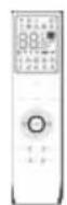
Remote controller

x2
AAA battery

x6
Screw
User manual
4-layers filter

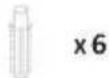
Extension Joint

x6
Plastic anchors

x2
Pipes rear support

Rigid pipe
x 2
Fresh air pipe

×4

Refrigerant pipe nuts
Wall sleeve cover
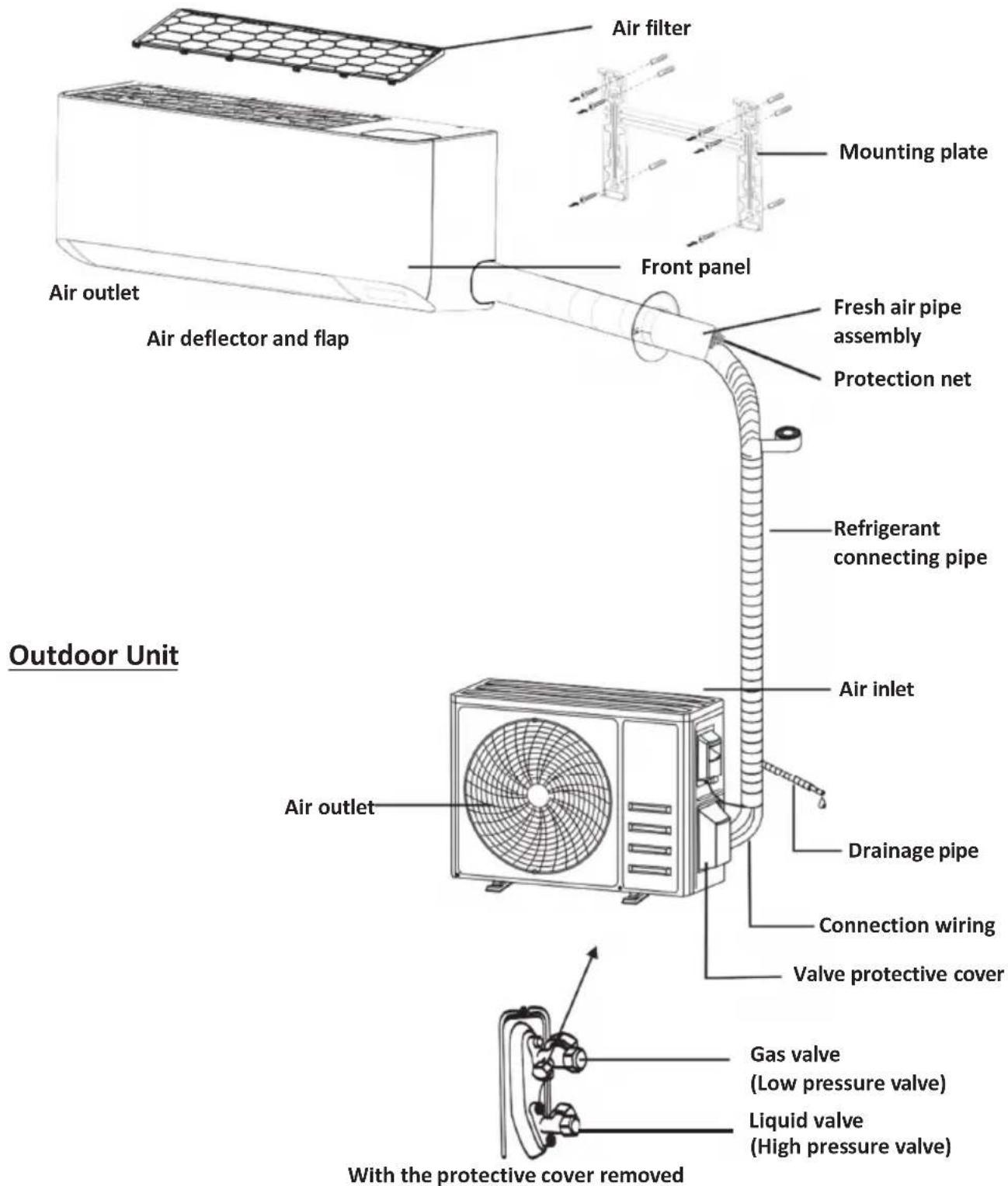
Outdoor Unit
x2
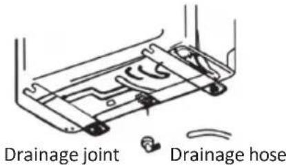
Drainage
hose

x2
Insulating tape

Sealant

Adapters

Drainage joint (some models do not have)

x2
Insulation pipe
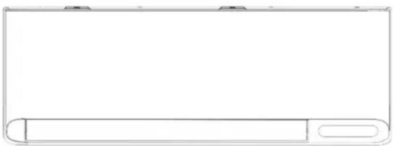
Indoor Unit
Note: This figure shown may be different from the actual object. Please take the latter as the standard.
Indoor Display
natural_image
Simple line drawing of a rectangular object with rounded ends and a horizontal bar at the bottom (no text or symbols)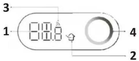
| No. | LED | Function |
| 1 |  | Indicator for Timer, temperature and Error codes. |
| 2 |  | Lights up when Fresh Air function is on. |
| 3 |  | Lights up when Wi-Fi is on. |
| 4 |  | Air quality status indicator. |
Note:
The air conditioner automatically adjusts the display brightness and buzzer sound according to the ambient light intensity. When the air conditioner detects that the ambient light is weak for a period of time, it will automatically turns off the display temporarily. If there is a remote control or APP operation, the display will display at a low brightness for a short time, and the buzzer will respond at a lower volume; When the air conditioner detects that the ambient light is strong for a period of time, exit the above operation.

The shape and position of switches and indicators may be different according to the model, but their function is the same.
Remote control DISPLAY
| No. | Symbols | Meaning |
| 1 |  | Battery indicator |
| 2 | Auto Mode | |
| 3 | Cooling Mode | |
| 4 | Dry Mode | |
| 5 | Fan only Mode | |
| 6 | Heating Mode | |
| 7 | ECO Mode | |
| 8 | Timer | |
| 9 | Temperature indicator | |
| 10 | Fan speed: Auto/ low/ low-mid/ mid/ mid-high/ high | |
| 11 | Mute function | |
| 12 | TURBO function | |
| 13 | Vertical swing | |
| 14 | Horizontal swing | |
| 15 | SLEEP function | |
| 16 | Health function | |
| 17 | I FEEL function | |
| 18 | 8°C heating function | |
| 19 | Signal indicator | |
| 20 | Gentle wind | |
| 21 | Child-Lock | |
| 22 | Display ON/OFF | |
| 23 | GEN function | |
| 24 | Self-Clean function | |
| 25 | Anti-Mildew | |
| 26 | Fresh air |
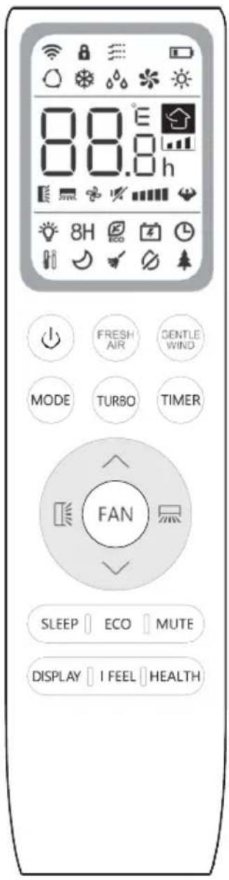

The display and some functions of the remote control may vary according to the model.
| No. | Button | Function |
| 1 | To turn on/off the air conditioner . | |
| 2 | ^ | To increase temperature, or Timer setting hours. |
| 3 | √ | To decrease temperature, or Timer setting hours. |
| 4 | MODE | To select the mode of operation (AUTO, COOL, DRY, FAN, HEAT). |
| 5 | ECO | To activate/deactivate the ECO function. |
| Long press to activate/deactivate the 8°C heating function . | ||
| 6 | TURBO | To activate/deactivate the TURBO function. |
| 7 | FAN | To select the fan speed of auto/mute/low/low-mid/mid/mid-high/high/turbo. |
| 8 | TIMER | To set the time for timer on/off. |
| 9 | SLEEP | To switch-on/off the functionSLEEP. |
| 10 | DISPLAY | To switch-on/off the LEDdisplay and the blue light |
| 11 | To enable/disable the vertical movement of the flap or to stop it at the desired position. | |
| 12 | To enable/disable the horizontal movement of the flap or to stop it at the desired position. | |
| 13 | I FEEL | To switch-on/off the IFEEL function. |
| 14 | MUTE | To switch-on/off the MUTE function. |
| Long press to activate/deactivate the GEN function | ||
| 15 | MODE + TIMER | To activate/deactivate the CHILD-LOCKfunction. |
| 16 | GENTLE WIND | To activate/deactivate the GENTLE WIND function. |
| 17 | HEALTH | To activate/deactivate the SELF-CLEAN function when switch OFF. |
| 18 | FRESH AIR | To activate/deactivate theFresh Air function and select the fan speed. |
The display and some functions of the remote control may vary according to the model.
The shape and position of buttons and indicators may vary according to the model, but their function is the same.
The unit confirms the correct reception of each button with the beep.
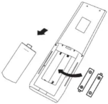
Replacement of Batteries
Remove the battery cover plate from the rear of the remote control, by sliding it in direction as the arrow.
Install the batteries according the direction (+ and -) shown on the Remote Control.
Reinstall the battery cover by sliding it into place.

Jse 2 pieces LRO3 AAA (1.5V) batteries.
Do not use rechargeable batteries. Replace the old batteries with new ones of the same type when the display is no longer legible. Do not dispose batteries as unsorted municipal waste. Collection of such waste separately for special treatment is necessary.
natural_image
Diagram of a battery internal structure with an arrow indicating rotation, showing battery, casing, and battery terminals (no text or symbols present)
For some models of the remote controller, you can program the temperature display between ^ C and ^ F .
- Press and hold the TURBO button over 5 seconds to get into the change mode;
- Press and hold the TURBO button, until it switch to °C and °F;
- Then release the pressing and wait for 5 seconds, the function will be selected.
Note:
- Direct the remote control toward the Air conditioner.
- Check that there are no objects between the remote control and the Signal receptor in the indoor unit.
- Never leave the remote control exposed to the rays of the sun.
- Keep the remote control at a distance of at least 1m from the television or other electrical appliances.
COOLING MODE
COOL

The cooling function allows the air conditioner to cool the room and reduce Air humidity at the same time.
To activate the cooling function (COOL), press the MODE button until the symbol ✦ appears on the display.
With the button √ or ∧ set a temperature lower than that of the room.
FAN MODE (Not FAN button)
FAN

Fan mode, air ventilation only.
To set the FAN mode, press MODE until appears on the display.
DRY MODE
DRY

This function reduces the humidity of the air to make the room more comfortable.
To set the DRY mode, Press MODE until appears in the display. An automatic function of pre-setting is activated.
AUTO MODE
AUTO

Automatic mode.
To set the AUTO mode, press MODE until appears on the display. In AUTO mode the run mode will be set automatically according to the room temperature.
HEATING MODE
HEAT

The heating function allows the air conditioner to heat the room.
To activate the heating function (HEAT), press the MODE button until the symbol ✿ appears on the display.
With the button √ or ∧ set a temperature higher than that of the room.

In HEATING operation, the appliance can automatically activate a defrost cycle, which is essential to clean the frost on the condenser so as to recover its heat exchange function. This procedure usually lasts for 2-10 minutes. During defrosting, indoor unit fan stop operation. After defrosting, it resumes to HEATING mode automatically.

(For North American market)
If necessary, you can press ECO button 10 times within 8 seconds under heating mode to start the forced defrosting. It will defrost the outdoor ice much faster.
FAN SPEED function (FAN button)
FAN

Change the operating fan speed.
Press FAN button to set the running fan speed, it can be set to AUTO/MUTE/LOW/LOW-MID/MID/MID-HIGH/HIGH/TURBO speed circularly.
flowchart
graph LR
    A["Start"] --> B{Flash}
    B --> C["End"]
    C --> D["Continue"]
    D --> E["Next Step"]
    E --> F["Next Step"]
    F --> G["Next Step"]
    G --> H["Next Step"]
    H --> I["Next Step"]
Child-Lock function
- Long press MODE and TIMER button together to active this function, and do it again to deactivate this function.
- Under this function, no single button will active.
TIMER function ---- TIMER ON
TIMER
To automatic switch on the appliance.
When the unit is switch-off, you can set the TIMER ON.
To set the time of automatic switch-on as below:
- Press TIMER button first time to set the switch-on, and [60h] will appear on the remote display and flashes.
- Press ^ or ▼ to button to set desired Timer-on time. Each time you press the button, the time increases/decreases by half an hour between 0 and 10 hours and by one between 10 and 24 hours.
- Press TIMER button second time to confirm.
- After Timer-on setting, set the needed mode (Cool/ Heat/ Auto/ Fan/ Dry), by press the MODE button. And set the needed fan speed, by press FAN button. And press ^ or √ to set the needed operation temperature.
CANCEL it by press TIMER button.
TIMER function ----TIMER OFF
TIMER
To automatic switch off the appliance.
When the unit is switch-on, you can set the TIMER OFF.
To set the time of automatic switch-off, as below:
- Confirm the appliance is ON.
- Press the TIMER button at first time to set the switch-off.
Press ^or ▼ to set the needed timer.
- Press TIMER button at the second time to confirm.
CANCEL it by press TIMER button.
Note: All programming should be operated within 5 seconds, otherwise the setting will be cancelled.
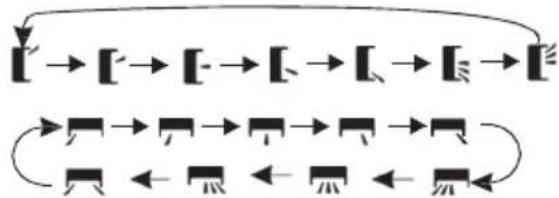
SWING function


- Press the button SWING to activate the louver, 1.1 Press to activate the horizontal flaps to swing from up to down, the will appear on the remote display.
1.2 Press 📁 to active the vertical deflectors to swing from left to right, the 📁 will appear on the remote display.
1.3 Do it again to stop the swing movement at the current angle.
-
If the vertical deflectors are positioned manually which placed under the flaps, they allow to move the air flow direct to rightward or leftward.
-
Long press or over 3 seconds to select more angles of the airflow direction.
flowchart
graph TD
    A["Start"] --> B["Step 1"]
    B --> C["Step 2"]
    C --> D["Step 3"]
    D --> E["Step 4"]
    E --> F["Step 5"]
    F --> G["Step 6"]
    G --> H["Step 7"]
    H --> I["Step 8"]
    I --> J["Step 9"]
    J --> K["Step 10"]
    K --> L["End"]
Never position the Flaps manually, the delicate mechanism might seriously damaged!
Never put fingers, sticks or other objects into the air inlet or outlet vents. Such accidental contact with live parts might cause unforeseeable damage or injury.
TURBO function
TURBO

To activate turbo function, press the TURBO button, and 🤕 will appear on the display.
Press again to cancel this function.
In COOL/HEAT mode, when you select TURBO feature, the appliance will turn to quick COOL or quick HEAT mode, and operate the highest fan speed to blow strong airflow.
REMOTE CONTROL
MUTE function
MUTE
- Press MUTE button to active this function, and 14 will appears on the remote display. Do it again to deactivate this function.
- When the MUTE function runs, the remote controller will display the auto fan speed, and the indoor unit will operate at lowest fan speed to be quiet feeling.
- When press FAN/ TURBO button, the MUTE function will be cancel. MUTE function can not be activated under dry mode.
ECO function
ECO

In this mode the appliance automatically sets the operation to save energy.
Press the ECO button, the ECO appears on the display, and the appliance will run in ECO mode. Press again to cancel it.
Note: The ECO function is available in both COOLING and HEATING modes.
SLEEP function
SLEEP

Pre-setting automatic operating program.
Press SLEEP button to activate the SLEEP function, and 🤩 appears on the display. Press again to cancel this function.
After 10 hours running in sleep mode, the air conditioner will change to the previous setting mode.
I FEEL function
I FEEL

Press I FEEL button to active the function, the

will appear on the remote display.
Do it again to deactivate this function.
This function enables the remote control to measure the temperature at its current location, and send this signal to the air conditioner to optimize the temperature around you and ensure the comfort.
DISPLAY function (Indoor display)
DISPLAY
Switch ON/OFF the LED display on panel.
Press DISPLAY button to switch off the LED display on the panel. Press again to switch on the LED display.
GEN function (energy saving)

When this function is activated, the LED display and the blue light switch off.
- Turn on the indoor unit at first, and long press MUTE button 3 seconds to active, and do it again to deactivate this function.
- Under this function, short press MUTE button to select the absorbed power limitation (L1 minimum, L2 average, L3 maximum).
- Select OFF and wait 2 seconds to exit it.
Reset Wi-Fi
- Method 1: Press button DISPLAY 6 times in 8 seconds.
- Method 2: Press button ECO 6 times in 8 seconds.
- Method 3: Long press MODE and ^over 3 seconds.
You will hear 2 beeps and CF or AP will show on the indoor display after the operation.
To view the wifi user manual, frame the QR CODE.

SELF-CLEAN function
To active this function, turn off the indoor unit at first, then press HEALTH button then you will hear a beep, [AC] will appear on the indoor LED, and will appear on the remote display.
- This function helps carry away the accumulated dirt, bacteria, etc from the indoor evaporator.
- This function will run about 30 minutes, and it will return to the pre-setting mode. You can press 🔒 button to cancel this function during the process.
You will hear 2 beeps when it's finished or cancelled.

It's normal if there is some noise during this function process, as plastic materials expand with heat and contract with cold.

We suggest operating this function at the following ambient conditions to avoid the activation of the safety devices.
| Indoor unit | Temp < 86°F (30°C) |
| Outdoor unit | 41°F (5°C) < Temp < 86°F (30°C) |

It's suggested to utilize this function every 3 months.
8°C heating function
- Long press ECO button over 3 seconds to active
this function, and 8 C (46 F) will appear on the remote display.
Do it again to deactivate this function.
- This function will auto start the heating mode when the room temperature is lower than 8^ C ( 46^ F), and it will return to standby if the temperature reaches 9^ C ( 48^ F).
- If the room temperature is higher than 18^ C ( 64^ F), the appliance will cancel this function automatically.
Gentle Wind function
- Turn on the indoor unit, and change to COOL mode, then press GENTLE WIND button or to active this function, will appear on the display.
Do it again to deactivate it.
- This function will auto close the vertical flaps, and give you the comfortable gentle wind feeling.
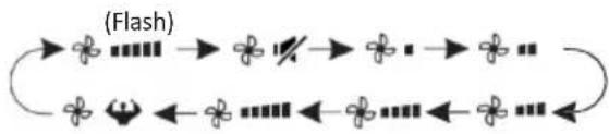
Fresh Air function
FRESH AIR
This function will pump the fresh air from outside to inside FRESH
Continue press AIR button until select your
desired Fresh Air fan speed or deactivate this function as circulation Low-Mid-High-OFF, then loose button.
The following indicator will appear on the display:
Auto fan speed

Low fan speed
(Flash)
Mid fan speed


High fan speed
OFF (no indicator)
Note:
- This function is available when in OFF/Heating Cooling/Fan/Auto mode.
- In OFF mode, the air conditioner may run automatically because of the big difference of temperature between indoor and outside.
- If the display shows the Fresh Air indicator and shows CL. It is necessary to replace the filter (duration 2160 hours)
and long press button
FRESH
AIR
over 5 seconds to reset the alarm.
TVOC function
This function enable to detect some kinds of harmful gases in the room and display the air quality status.
If the unit is equipped with this function, when the unit is operation, it will display the following indicator states according to the detected concentration of different harmful gases.
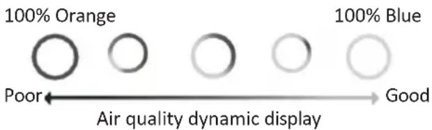
- The more orange color in the circle, the worse the air quality is (Note: the air quality detection object is TVOC, total concentration of volatile organic compounds).
- All panel display lights including TVOC can be turned off by pressing the DISPLAY button.
- Turning on the Fresh Air function can improve the indoor air quality, but when the outdoor air pollution is serious, it is recommended to turn off the Fresh Air function.
The detection of TVOC is mainly aimed at various volatile organic compounds, even the use of perfume, toilet water, alcohol, air fresheners, etc., will also lead to an increase in the detected TVOC concentration.
The TVOC sensor must be stabilize every time it is powered on, please wait patiently for about 10 minutes for a correct detection.
Depending on the brand or working principle of the testing equipment, TVOC testing results may vary.
OPERATION INSTRUCTIONS
- Attempt to use the air conditioner under the temperature beyond the specified range may cause the air conditioner protection device to start. Therefore, try to use the air conditioner in the following temperature conditions.
Inverter air conditioner:
| Temperature\MODE | Heating Cooling | Dry | |
| Room temperature | 0°C~30°C | 17°C~32°C | |
| Outdoor temperature | -20°C~30°C | -15°C~53°C | |
With the power supply connected, restart the air conditioner after shutdown, or switch it to other mode during operation, and the air conditioner protection device will start. The compressor will resume operation after 3 minutes.
Characteristics of heating operation (applicable to Heating pump)
Preheating:
When the heating function is enabled, the indoor unit will take 2\~5 minutes for preheating, after that the air conditioner will start heating and blows warm air.
Defrosting:
During heating, when the outdoor unit frosted, the air conditioner will enable the automatic defrosting function to improve the heating effect. During defrosting, the indoor and outdoor fans stop running. The air conditioner will resume heating automatically after defrosting finish.
INSTALLATION PRECAUTIONS
Pipe Length and Additional Refrigerant
| Inverter Models Capacity (Btu/h) | 9K-12K |
| Length of pipe covered by pre-charge | 5m |
| Maximum distance between indoor and outdoor unit | 15m |
| Additional refrigerant charge | 15g/m |
| Max. diff. in level between indoor and outdoor unit | 10m |
| Typeof refrigerant | R32 |
Torque Parameters
| PIPESize | Newton meter[N x m] | Pound-force foot (lbf-ft) | Kilogram-force meter (kgf-m) |
| 1/4" (Φ6.35) | 15 - 20 | 11.1 - 14.8 | 1.5 - 2.0 |
| 3/8" (Φ9.52) | 31 - 35 | 22.9 - 25.8 | 3.2 - 3.6 |
| 1/2" (Φ 12) | 45 - 50 | 33.2 - 36.9 | 4.6 - 5.1 |
| 5/8" (Φ 15.88) | 60 - 65 | 44.3 - 48.0 | 6.1 - 6.6 |
Connection wires
| INVERTER TYPEMODEL capacity (Btu/h) | 9k /12 | |
| sectional area | ||
| Power supply cable | N | 1.0mm^2 |
| L | 1.0mm^2 | |
| [17208] | 1.0mm^2 | |
| Connection cable | N | 1.0mm^2 |
| L | 1.0mm^2 | |
| 1 | 1.0mm^2 | |
| [4464] | 1.0mm^2 | |

Note: This table is only for reference, the installation shall meet the requirements of local laws and regulations.
INDOOR UNIT INSTALLATION
To perform installation of the indoor unit, please refer to the instructions below.
For further information, please visit the product page on the website www.olimpiasplendid.com
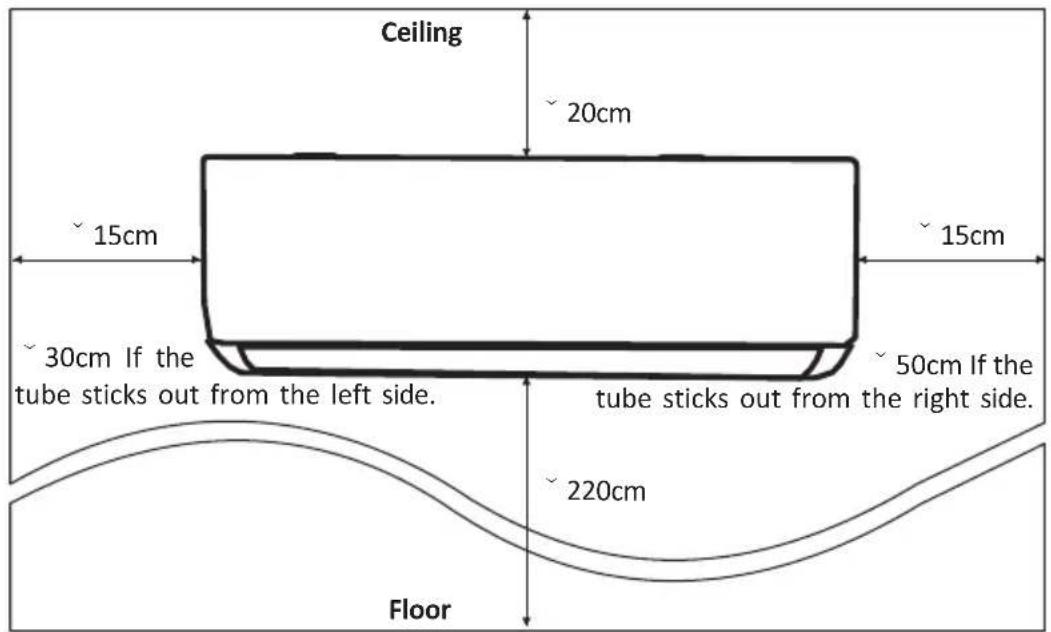
Step1: Select Installation location
1.1 Ensure the installation complies with the installation minimum dimensions (defined below) and meets the minimum and maximum connecting piping length and maximum change in elevation as defined in the System Requirements section.
1.2 Air inlet and outlet will be clear of obstructions, ensuring proper airflow throughout the room.
1.3 Condensate can be easily and safely drained.
1.4 All connections can be easily made to outdoor unit.
1.5 Indoor unit is out of reach of children.
1.6 A mounting wall strong enough to withstand four times the full weight and vibration of the unit.
1.7 Filter can be easily accessed for cleaning.
1.8 Leave enough free space to allow access for routine maintenance.
1.9 Install at least 3 m away from the antenna of TV set or radio. Operation of the air conditioner may interfere with radio or TV reception in areas where reception is weak. An amplifier may be required for the affected device.
1.10 Do not install in a laundry room or by a swimming pool due to the corrosive environment.
Minimum Indoor Clearances
INDOOR UNIT INSTALLATION
Step2: Install Mounting Plate
2.1 Take the mounting plate from the back of indoor unit.
2.2 Ensure to meet the minimum installation dimension requirements as step 1, according to the size of mounting plate, determine the position and stick the mounting plate close to the wall.
2.3 Adjust the mounting plate to a horizontal state with a spirit level, then mark out the screw hole positions on the wall.
2.4 Put down the mounting plate and drill holes in the marked positions with drill.
2.5 Insert expansion rubber plugs into the holes, then hang the mounting plate and fix it with screws.
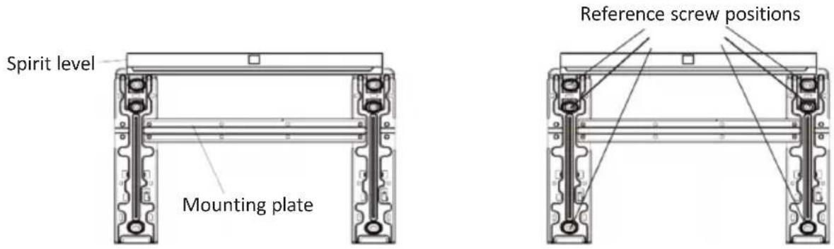
Note:
(I) Make sure the mounting plate is firm enough and flat against the wall after installation.
(II) This figure shown may be different from the actual object, please take the latter as the standard.
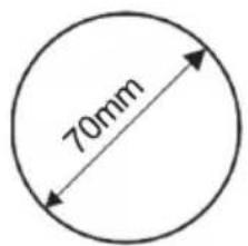
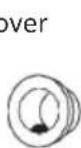
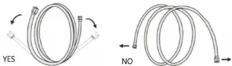
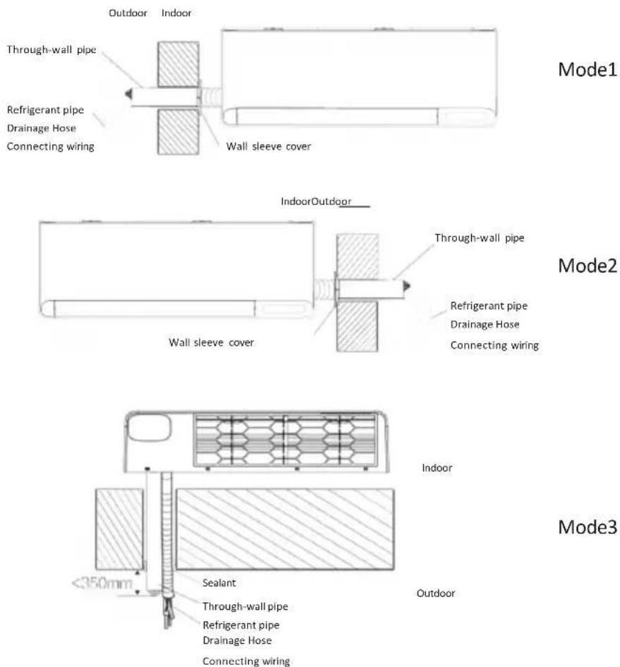
Step3: Drill Wall Holes
3.1 Three optional piping modes show be determined
Mode1: Left, the Fresh air pipe, the refrigerant piping, the drainage pipe, and connecting cables all are through one hole to the outside.
Mode2: Right, the Fresh air pipe, the refrigerant piping, the drainage pipe, and connecting cables all are through one hole to the outside
Mode3: Back, the Fresh air pipe, the refrigerant piping, the drainage pipe, and connecting cables go through two side-by-side wall holes.
3.2 For Mode3, follow the reference size for mounting plate and hole to determine location.
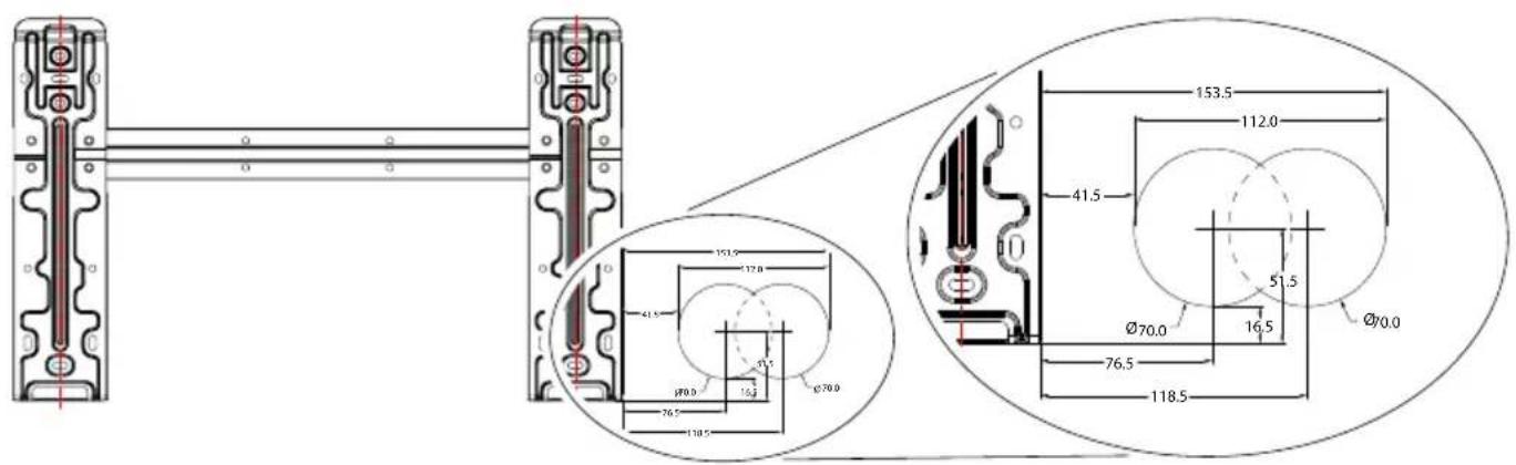
INDOOR UNIT INSTALLATION
For Mode1 and Mode2, Determine the location of wall hole base on the following size.
3.3 Drill the wall hole with 70mm core drill and with small oblique angle lower than the indoor end about 5mm to 10mm.
3.4 Place the wall sleeve and wall sleeve cover(both are optional parts) to protect the connection parts.
Wall sleeve Cover (Optional)
Indoor

natural_image
Pure mechanical cross-section diagram without any text, numbers, or symbolsWall sleeve (Optional)
Outdoor
5-10mm
Small bolique angle
Caution:
When drill the wall hole, maker sure to avoid wires, plumbing and other sensitive components.
* If the internal unit is on a perimeter wall and installation on the back is not envisaged, the hole must be performed on the adjacent perimeter wall (right or left) and not on the same perimeter wall where the internal unit is positioned, since 90° turns of the pipelines cannot be installed.
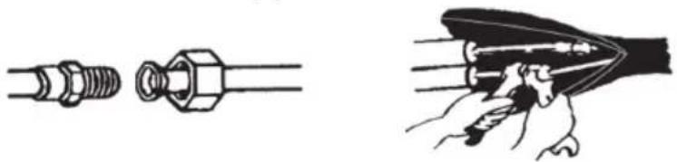
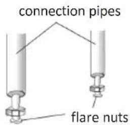
Step4: Connecting Refrigerant Pipe
3.1 According to the wall hole position, select the appropriate piping mode.
There are three optional piping modes for indoor units as shown in the figure below:
In Piping Mode 1 or Piping Mode 3, a notch should be made by using scissors to cut the plastic sheet of piping outlet and cable outlet on the corresponding side of the indoor unit.
Note: When cutting off the plastic sheet at the outlet, the cut should be trimmed to smooth.
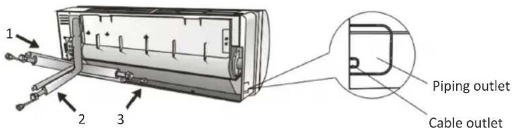
3.2 Bending the connecting pipes with the port facing up as shown in the figure.
3.3 Take off the plastic cover in the pipe ports and take off the protective cover on the end of piping connectors.
3.4 Check whether there is any sundry on the port of the connecting pipe and make ensure the port is clean.
3.5 After align the center, rotate the nut of the connecting pipe to tighten the nut as tightly as possible by hand.
3.6 Use a torque wrench to tighten it according to the torque values in the torque requirements table; (Refer to the torque requirements table on section INSTALLATION PRECAUTIONS)
3.7 Wrap the joint with the insulation pipe.
natural_image
Technical illustration showing two types of mechanical fasteners: threaded and threaded fasteners, with a close-up of the internal structure (no text or symbols present)Step5: Connect Drainage Hose
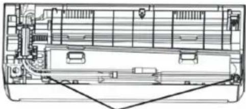
5.1 Adjust the drainage hose(if applicable)
In some model, both sides of the indoor unit are provided with drainage ports, you can choose one of them to attach the drainage hose. And plug the unused drain port with the rubber attached in one of the ports.
natural_image
Technical line drawing of a mechanical assembly with internal components and no visible text or symbolsDrainage ports
5.2 Connect the drainage hose to the drainage port, ensure the joint is firm and the sealing effect is good.
5.3 Wrap the joint firmly with teflon tape to ensure no leaks.
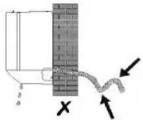
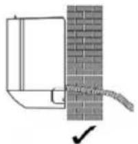
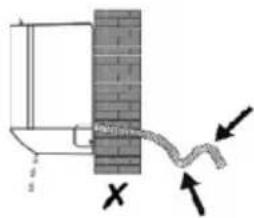
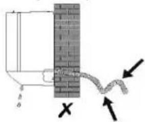
Note: Make sure there is no twists or dents, and the pipes should be placed obliquely downward to avoid blockage, to ensure proper drainage.
natural_image
Diagram of a wall-mounted device with a brick wall and a curved cable, no text or symbols present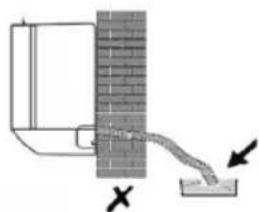
natural_image
Diagram showing a pipe flowing from a brick wall to a small container with arrows indicating flow direction (no text or symbols)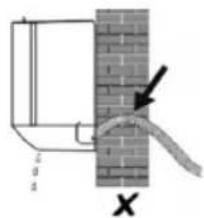
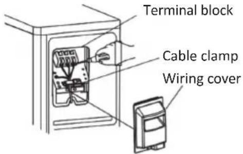
Step6: Connect Wiring
6.1 Choose the right cables size determined by the maximum operating current on the nameplate. (Check the cables size refer to section INSTALLATION PRECAUTIONS)
6.2 Open the front panel of indoor unit.
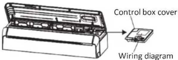
6.3 Use a screwdriver, open the electric control box cover, to reveal the terminal block.
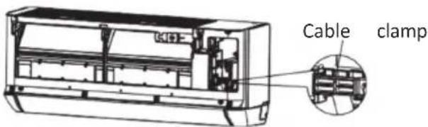
6.4 Unscrew the cable clamp.
6.5 Insert one end of the cable into the position of control box from the back of the right end of the indoor unit.
6.6 Connect the wires to corresponding terminal according to the wiring diagram on the electric control box cover. And make sure that they are well connected.
6.7 Screw the cable clamp to fasten the cables.
6.8 Reinstall the electric control box cover and front panel.
6.9 For some models, the power cables and connection cables are pre-installed on the machine at the factory.
INDOOR UNIT INSTALLATION
Step7: Connecting Fresh Air Pipe and place the filter
7.1 According to the wall hole position, select the appropriate piping mode.
Mode1: Left, together with refrigerant piping, the drainage pipe, and connecting cables. Mode2: Right, together with refrigerant piping, the drainage pipe, and connecting cables. Mode3: Back, the fresh air pipe is not bundled with other pipes.
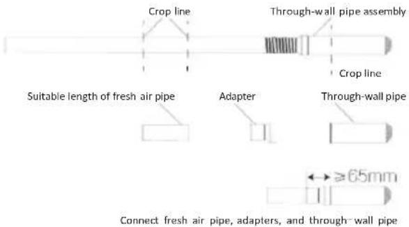
7.2 Measure the length of the fresh air pipe assembly.
In the "1" and "2" modes, if needed, extend the fresh air tube by uniting the extensions and the rigid tube.

For mode 1: Measure the distance between the left bottom corner of the mounting plate and the center of the wall hole, the length of the fresh air pipe assembly is equal to the measured length plus 650mm.
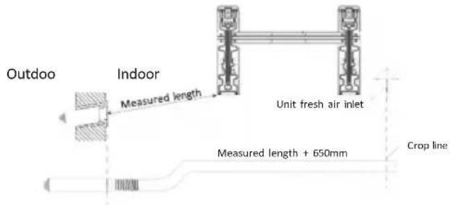
For mode 2: Measure the distance between the left bottom corner of the mounting plate and the center of the wall hole, the length of the fresh air pipe assembly is equal to the measured length.
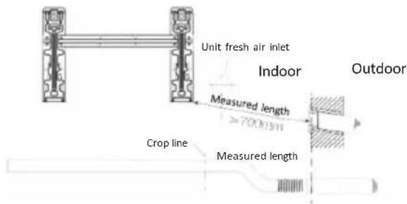
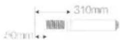
For mode 3: The length of the fresh air pipe assembly is 310mm and the exposed length of the fresh air pipe is 50mm.
Step7: Connecting Fresh Air Pipe and place the filter
7.3 Adjusting the length of the fresh air pipe assembly
According to the installation environment, determine to adjust the length of fresh air pipe assembly.
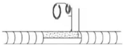
7.3.1 Shorten the length
Cut the fresh air pipe to the appropriate length, keeping the section with the through-wall pipe.
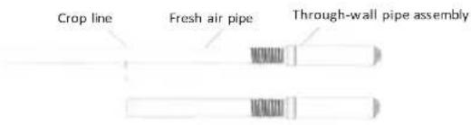
If it is nessary to cut the through-wall pipe assembly due to installation needs. first, cut the through-wall pipe assembly to a suitable length. Then cut a piece of new air pipe of a suitable length. Take out the adapter from the accessory bag, and insert the adapter into the through-wall pipe and fix it firmly with glue. Finally, screw the suitable new air pipe into the adapter.
Note:
-
The overlapping part of the adapter and the through-wall pipe needs to be pressed flat with tools and cannot be warped:
-
The adapter cannot be forced into the through-wall pipe, otherwise it may cause the connecting part to warp, and the distance between the round pipe end of the adapter and the through-wall pipe is ≥ 65mm;
7.3.2 Increase the length
Proceed as shown in the figure below:
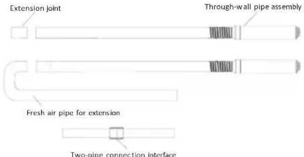
Note: The number of bends of the fresh air pipe and the length of the pipe will affect the amount of fresh air. It is recommended to use the mode 3 and avoid increasing the length of the fresh air pipe when the installation conditions allow.
INDOOR UNIT INSTALLATION
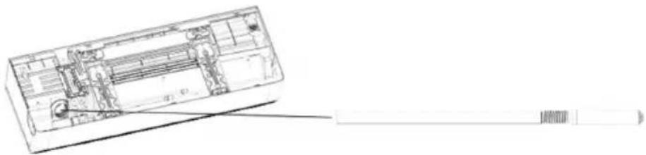
Step7: Connecting Fresh Air Pipe and place the filter
7.4 Screw the fresh air pipe into the fresh air inlet hole at the back of the indoor unit.
natural_image
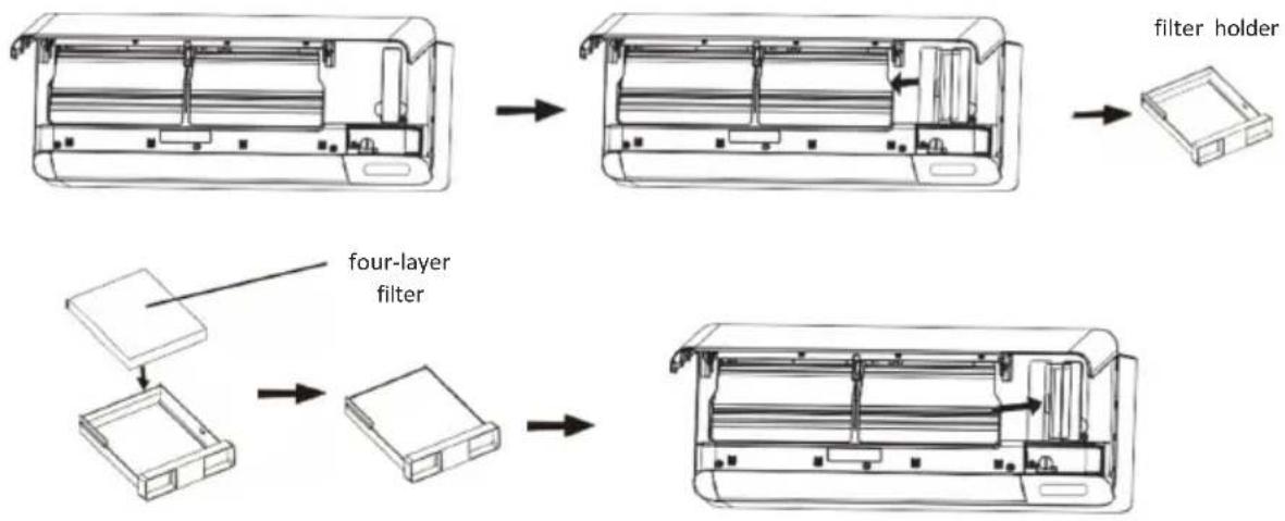
Technical line drawing of a rectangular electronic device with internal components and a cable extending from it (no text or symbols)7.5 Open the indoor panel and take out the filter holder, place the four-layer filter for fresh air then restore the holder.
INDOOR UNIT INSTALLATION
Step8: Wrap Piping and Cable
After the refrigerant pipes, connecting wires and drainage hose are all installed, in order to save space, protect and insulate them, it must be bundle with insulating tape before passing them through the wall hole.
8.1 Arrange the pipes, cables and drainage hose well as the following picture.
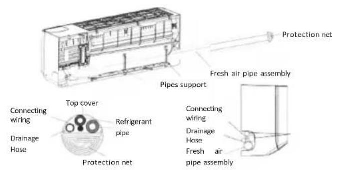
Mode1
After arrange all pipes and cables, take the pipes support out of the accessories of fresh air. Insert into the slot as the picture to fix the pipes.
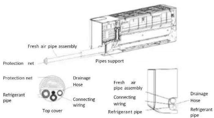
Mode2
After arrange all pipes and cables, take the pipes support out of the accessories of fresh air. Insert into the slot as the picture to fix the pipes.
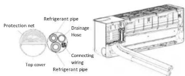
Mode3
Note: Avoid crossing and bending of parts.
8.2 Using the insulating tape wrap the fresh air pipes, the refrigerant pipes, connecting wires and drainage hose together tightly.
natural_image
Simple line drawing of a pipe or pipe with a curved pipe and a base, no text or symbols present.Step9: Mount Indoor Unit
9.1 Slowly pass the refrigerant pipes, connecting wires and drainage hose wrapped bundle through the wall hole.
92 Hook the top of indoor unit on the mounting plate.
9.3 Apply slight pressure to the left and right sides of the indoor unit, make sure the indoor unit is hooked firmly.
9.4 Push down the bottom of indoor unit to let the snaps onto the hooks of the mounting plate, and make sure it is hooked firmly.
Note:
- The distance between the fresh air inlet and the wall should not exceed 350mm;
- During installation, the fresh air pipe assembly can be rotated at an appropriate angle according to the position of the outdoor unit, so that the connecting pipe does not block the fresh air inlet.
- The fresh air pipe should be slightly inclined downward, and there should be no rising section to prevent rainwater from entering the room.
- If it is necessary to bend the fresh air pipe, the minimum radius of the bend of the fresh air pipe should be greater than 60mm, otherwise it may affect the fresh air effect.
- The fresh air inlet should not be placed in the air outlet of the outdoor unit, in a closed space or in a place with bad air.
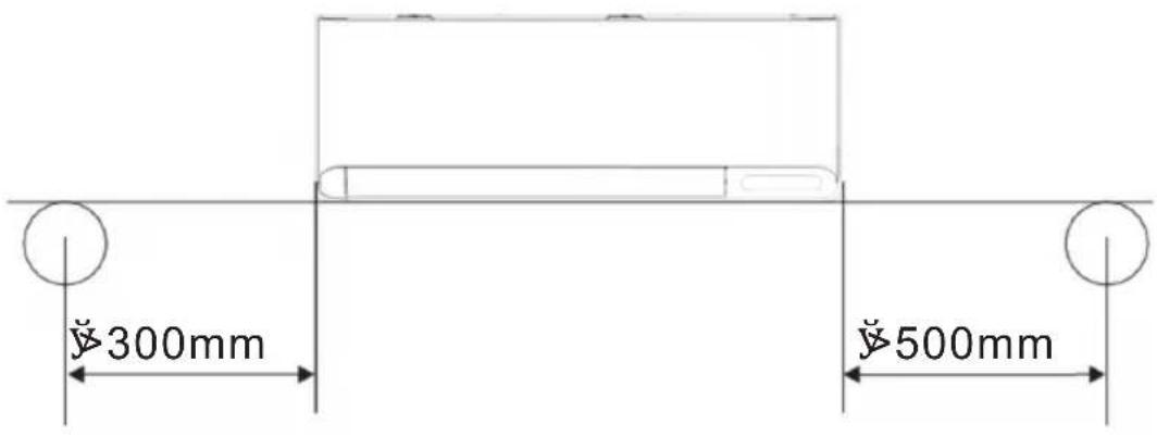
OUTDOOR UNIT INSTALLATION
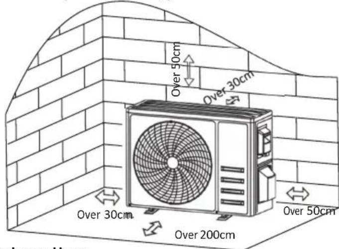
Step1: Select Installation Location
Select a site that allows for the following:
1.1 Do not install the outdoor unit near sources of heat, steam or flammable gas.
1.2 Do not install the unit in too windy or dusty places.
1.3 Do not install the unit where people often pass. Select a place where the air discharge and operating sound will not disturb the neighbors.
1.4 Avoid installing the unit where it will be exposed to direct sunlight (other wise use a protection, if necessary, that should not interfere with the air flow).
1.5 Reserve the spaces as shown in the picture for the air to circulate freely.
1.6 Install the outdoor unit in a safe and solid place.
1.7 If the outdoor unit is subject to vibration, place rubber blankets onto the feet of the unit.
Step2: Install Drainage Hose
2.1 This step only for heating pump models.
2.2 Insert the drainage joint to the hole at the bottom of the outdoor unit.
2.3 Connect the drainage hose to the joint and make the connection well enough.
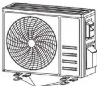
Step3: Fix Outdoor Unit
3.1 According to the outdoor unit installation dimensions to mark the installation position for expansion bolts.
3.2 Drill holes and clean the concrete dust and place the bolts .
3.3 If applicable install 4 rubber blankets on the hole before place the outdoor unit (Optional). This will reduce vibrations and noise.
3.4 Place the outdoor unit base on the bolts and pre-drilled holes.
3.5 Use wrench to fix the outdoor unit firmly with bolts.
Note:
The outdoor unit can be fixed on a wall-mounting bracket. Follow the instruction of the wall-mounting bracket to fix the wall-mounting bracket on the wall, and then fasten the outdoor unit on it and keep it horizontal.
The wall-mounting bracket must be able to support at least 4 times of the weight of outdoor unit.
natural_image
Line drawing of a dual-panel air conditioner unit with fan blades and ventilation slots (no text or symbols)Install 4 rubber blankets (Optional)
OUTDOOR UNIT INSTALLATION
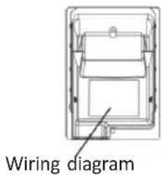
Step4: Install Wiring
4.1 Use a phillips screwdriver to unscrew wiring cover, grasp and press it down gently to take it down.
4.2 Unscrew the cable clamp and take it down.
4.3 By following the WIRING DIAGRAM (see the last page of this manual), connect the wires to their respective terminals making sure that all the connections are firm and safe.
4.4 Reinstall the cable clamp and wiring cover.
Note: When connecting the wires of indoor and outdoor units, the power should be cut off.
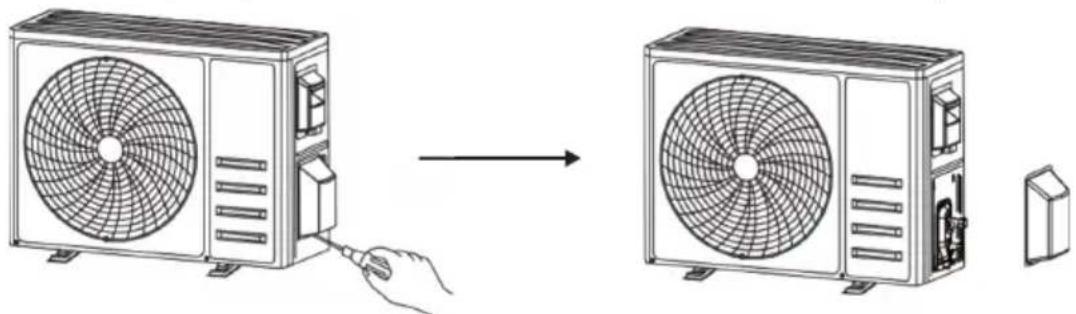
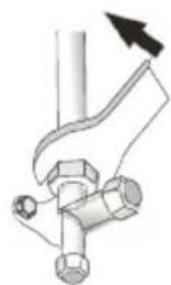
Step5: Connecting Refrigerant Pipe
5.1 Unscrews the valve cover, grasp and press it down gently to take it down (if the valve cover is applicable).
5.2 Remove the protective caps from the end of valves.
5.3 Take off the plastic cover in the pipe ports and check whether there is any sundry on the port of the connecting pipe and make ensure the port is clean.
5.4 After align the center, rotate the flare nut of the connecting pipe to tighten the nut as tightly as possible by hand.
5.5 Use a spanner hold the body of the valve and use a torque wrench to tighten the flare nut according to the torque values in the torque requirements table.
(Refer to the torque requirements table on section INSTALLATION PRECAUTIONS)
natural_image
Diagram showing airflow from a fan to a second fan, with a hand inserting a cable (no text or symbols present)Take down the valve cover
natural_image
Pure mechanical diagram showing a pipe joint with a valve and bolt, no text or symbols presentOUTDOOR UNIT INSTALLATION
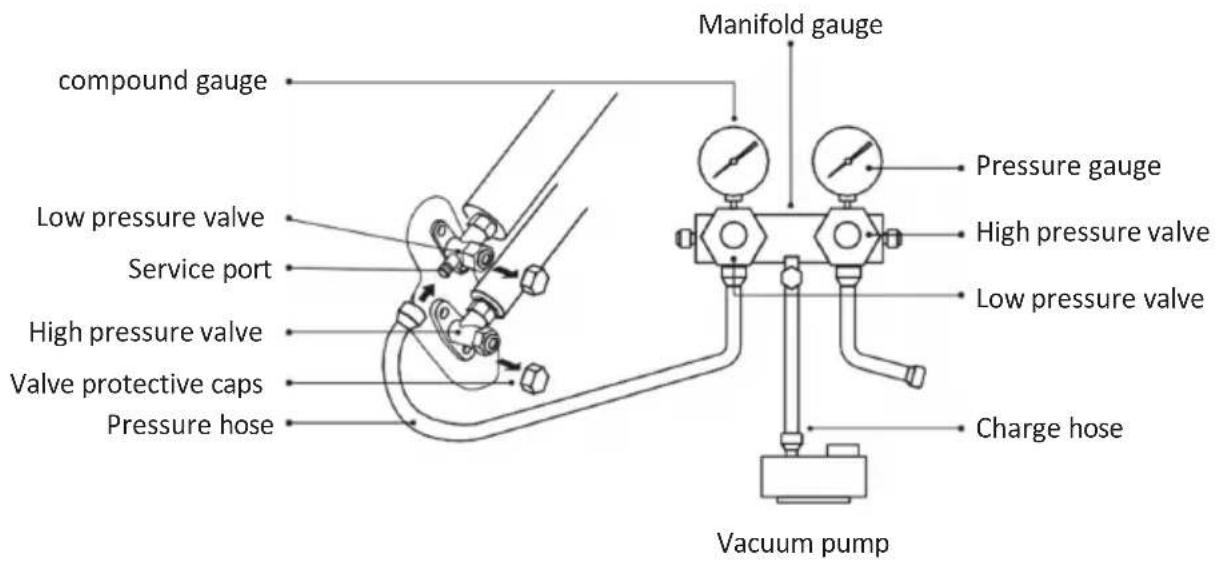
Step6: Vacuum Pumping
6.1 Use a spanner to take down the protective caps from the service port, low pressure valve and high pressure valve of the outdoor unit.
6.2 Connect the pressure hose of manifold gauge to the service port on the outdoor unit low pressure valve.
6.3 Connect the charge hose from the manifold gauge to the vacuum pump.
6.4 Open the low pressure valve of the manifold gauge and close the high pressure valve.
6.5 Turn on the vacuum pump to vacuum the system.
6.6 The vacuum time should not be less than 15 minutes, or make sure the compound gauge indicates -0.1 MPa (-76 cmHg)
6.7 Close the low pressure valve of the manifold gauge and turn off the vacuum.
6.8 Hold the pressure for 5 minutes, make sure that the rebound of compound gauge pointer does not exceed 0.005 MPa.
6.9 Open the low pressure valve counterclockwise for 1/4 turn with hexagonal wrench to let a little refrigerant fill in the system, and close the low pressure valve after 5 seconds and quickly remove the pressure hose.
6.10 Check all indoor and outdoor joints for leakage with soapy water or leak detector.
6.11 Fully open the low pressure valve and high pressure valve of the outdoor unit with hexagonal wrench.
6.12 Reinstall the protective caps of the service port, low pressure valve and high pressure valve of the outdoor unit.
6.13 Reinstall the valve cover.
Inspections Before Test Run
Do the following checks before test run.
| Description | Inspection method |
| Electrical safety inspection | Check whether the power supply voltage complies with specification.Check whether there is any wrong or missing connection between the power lines, signal line and earth wires.Check whether the earth resistance and insulation resistance comply with requirements. |
| Installation safety inspection | Confirm the direction and smoothness of drainage pipe.Confirm that the joint of refrigerant pipe is installed completely.Confirm the safety of outdoor unit, mounting plate and indoor unit installation.Confirm that the valves are fully open.Confirm that there are no foreign objects or tools left inside the unit.Complete installation of indoor unit air inlet grille and panel. |
| Refrigerant leakage detection | The piping joint, the connector of the two valves of the outdoor unit, the valve spool, the welding port, etc., where leakage may occur.Foam detection method:Apply soapy water or foam evenly on the parts where leakage may occur, and observe whether bubbles appear or not, if not, it indicates that the leakage detection result is safe.Leak detector method:Use a professional leak detector and read the instruction of operation, detect at the position where leakage may occur.The duration of leak detection for each position should last for 3 minutes or more;If the test result shows that there is leakage, the nut should be tightened and tested again until there is no leakage;After the leak detection is completed, wrap the exposed pipe connector of indoor unit with thermal insulation material and wrap with insulation tape. |
Test Run Instruction
- Turn on the power supply.
- Press the ON/OFF button on the remote controller to turn on the air conditioner.
- Press the Mode button to switch the mode COOL and HEAT.
In each mode set as below:
COOL-Set the lowest temperature
HEAT-Set the highest temperature
- Run about 8 minutes in each mode and check all functions are properly run and respond the remote controller. Functions check as recommended:
4.1 If the outlet air temperature respond the cool and heat mode
4.2 If the water drains properly from the drainage hose
4.3 If the Louver and deflectors(optional) rotate properly
TEST OPERATION
- Observe the test run state of the air conditioner at least 30 minutes.
- After the successfully test run, return the normal setting and press ON/OFF button on the remote controller to turn off the unit.
- Inform the user to read this manual carefully before use, and demonstrate to the user how to use the air conditioner, the necessary knowledge for service and maintenance, and the reminder for storage of accessories.
Note:
If the ambient temperature is excess the range refer to section OPERATION INSTRUCTIONS, and it can not run COOL or HEAT mode, lift the front panel and refer to the emergency button operation to run the COOL and HEAT mode.
MAINTENANCE
| Warning | When cleaning, you must shut down the machine and cut off the power supply for more than 5 minutes.Under no circumstances should the air conditioner be flushed with water.Volatile liquid (e.g. thinner or gasoline) will damage the air conditioner, so only use soft dry cloth or wet cloth dipped with neutral detergent to clean the air conditioner.Pay attention to cleaning the filter screen regularly to avoid dust covering which will affect the filter screen effect. When the operating environment is dusty, the cleaning frequency should be increased appropriately.After removing the filter screen, do not touch the fins of the indoor unit to avoid scratching. | |
| Clean the unit | 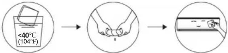 Wring it dry Gentle wipe the unit surfaceTip: Wipe frequently to keep air conditioner clean and good appearance . Wring it dry Gentle wipe the unit surfaceTip: Wipe frequently to keep air conditioner clean and good appearance . | |
| Disassembly and assembly of filter | Grasp the raised handle on the filter by hand, and then pull the filter out in the direction deviating from the unit, so that the upper edge of the filter is separated from the unit.The filter can be removed by lifting the filter upwards.When installing the filter, first insert the lower end of the filter screen into the corresponding position of the unit, and then squeeze the upper end of the filter into the corresponding buckling position of the unit body.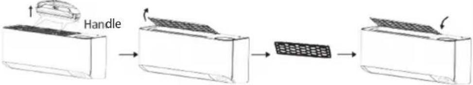 | |
| Clean the filter | 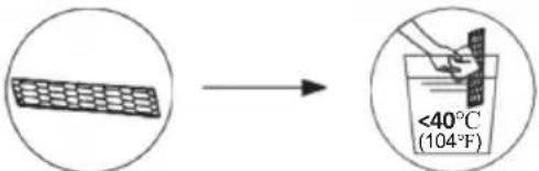 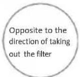 Take out the filter Clean the filter with Replace the filter from the unit soapy water and air dry itTip: When you find accumulated dust in the filter, please clean the filter in time to ensure the clean, healthy and efficient operation inside the air conditioner. Take out the filter Clean the filter with Replace the filter from the unit soapy water and air dry itTip: When you find accumulated dust in the filter, please clean the filter in time to ensure the clean, healthy and efficient operation inside the air conditioner. | |
| Cleaning or replace filter of Fresh Air | First, Open the panel and take out the filter holder.Use a dust catcher to clean the filter or replace a new one.We suggest replace the filter 6 months or when get the reminder indicator CL on the indoor display.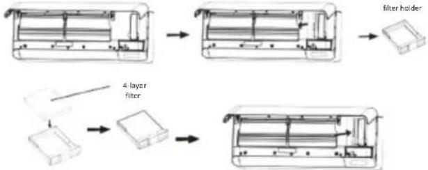 | |
| Service and maintenance | When the air conditioner is not in use for a long time, do the following work:Take out the batteries of the remote controller and disconnect the power supply of the air conditioner.When starting to use after long-term shutdown:Clean the unit and filter screen;Check whether there are obstacles at the air inlet and outlet of indoor and outdoor units;Check whether the drain pipe is unobstructed;Install the batteries of the remote controller and check whether the power is on. | |
TROUBLESHOOTING
| MALFUNCTION | POSSIBLE CAUSES |
| The appliance does not operate | Power failure/plug pulled out. |
| Damaged indoor/outdoor unit fan motor. | |
| Faulty compressor thermomagnetic circuit breaker. | |
| Faulty protective device or fuses. | |
| Loose connections or plug pulled out. | |
| It sometimes stops operating to protect the appliance. | |
| Voltage higher or lower than the voltage range. | |
| Active TIMER-ON function. | |
| Damaged electronic control board. | |
| Strange odor | Dirty air filter. |
| Noise of running water | Back flow of liquid in the refrigerant circulation. |
| A fine mist comes from the air outlet | This occurs when the air in the room becomes very cold, for example in the YCOOLING Y or YDEHUMIDIFYING/DRY Y modes. |
| A strange noise can be heard | This noise is made by the expansion or contraction of the front panel due to variations in temperature and does not indicate a problem. |
| Insufficient airflow, either hot or cold | Unsuitable temperature setting. |
| Obstructed air conditioner intakes and outlets. | |
| Dirty air filter. | |
| Fan speed set at minimum. | |
| Other sources of heat in the room. | |
| No refrigerant. | |
| The appliance does not respond to commands | Remote control is not close enough to indoor unit. |
| The batteries of remote control need to be replaced. | |
| Obstacles between remote control and signal receiver in indoor unit. | |
| The display is off | Active DISPLAY function. |
| Power failure. | |
| Switch off the air conditioner immediately and cut off the power supply in the event of: | Strange noises during operation. |
| Faulty electronic control board. | |
| Faulty fuses or switches. | |
| Spraying water or objects inside the appliance. | |
| Overheated cables or plugs. | |
| Very strong smells coming from the appliance. |
ERROR CODE ON THE DISPLAY
In case of error, the display on the indoor unit shown the following error codes:
| Display | Description of the trouble |
| E1 | Indoor room temperature sensor fault |
| E2 | Indoor pipe temperature sensor fault |
| E3 | Outdoor pipe temperature sensor fault |
| E4 | Refrigerant system leakage or fault |
| E6 | Malfunction of indoor fan motor |
| E7 | Outdoor ambient temperature sensor fault |
| E0 | Indoor and outdoor communication fault |
| E8 | Outdoor discharge temperature sensor fault |
| E9 | Outdoor IPM module fault |
| EA | Outdoor current detect fault |
| EE | Outdoor PCB EEPROM fault |
| EF | Outdoor fan motor fault |
| EX | Outdoor suction temperature sensor fault |
| CL | Filter cleaning reminder |
MISES EN GARDE GÉNÉRALES....2
NOM DES PIÈCES....13
TÉLÉCOMMANDE....15
INSTRUCTIONS D'UTILISATION......23
PRÉCAUTIONS D'INSTALLATION....24
INSTALLATION DE L'UNITÉ INTÉRIEURE ....25
INSTALLATION DE L'UNITÉ EXTÉRIEURE...35
FONCTIONNEMENT D'ESSAI ....38
ENTRETIEN 39
DÉPANNAGE....41
ÉLEMINATION
natural_image
Line drawing of a smartphone with rounded corners and a horizontal bar (no text or symbols)

natural_image
Diagram of a battery pack assembly with arrows indicating components (no text or symbols)natural_image
Technical line drawing of a mechanical frame assembly with no visible text or symbolsNote :
Manchon mural (en option)
Extérieur
5-10 mm
Petit angle oblique
Attention :
natural_image
Illustration of two mechanical components: a threaded bolt and a hexagonal nut, with a hand holding a tool (no text or symbols present)INSTALLATION DE L'UNITÉ INTÉRIEURE
natural_image
Technical line drawing of a mechanical assembly with internal components and no visible text or symbolsOrifices de drainage
natural_image
Simple line drawing of a wall-mounted device next to a brick wall, with a checkmark indicating a detail (no text or symbols present)
natural_image
Diagram showing a pipe flowing from a brick wall to a container with an arrow indicating direction (no text or symbols)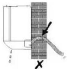
flowchart
graph LR
    A["Initial State"] --> B["Step 1"]
    B --> C["Step 2"]
    C --> D["Final Output"]
natural_image
Technical line drawing of a device internal structure with no visible text or symbolsnatural_image
Simple line drawing of a pipe or tube with a circular object inserted into the middle section (no text or symbols)INSTALLATION DE L'UNITÉ INTÉRIEURE
natural_image
Line drawing of a rectangular air conditioner unit with a circular fan and ventilation slots (no text or symbols)Installer 4 couvertures en caoutchouc (en option)
INSTALLATION DE L'UNITÉ EXTÉRIEURE
natural_image
Line drawing of a two-part HVAC system showing fan installation and cooling process (no text or symbols)natural_image
Diagram of a hand holding a valve with a black arrow indicating direction (no text or symbols)INSTALLATION DE L'UNITÉ EXTÉRIEURE
natural_image
Line drawing of a smartphone with rounded corners and a horizontal screen (no text or symbols)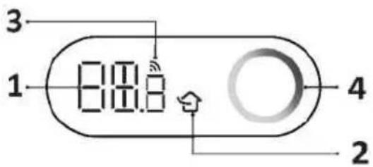
natural_image
Diagram of a battery pack assembly with arrows indicating components (no text or symbols)flowchart
graph LR
    A["Start"] --> B["Circle with tick marks"]
    B --> C["Circle with cross marks"]
    C --> D["Circle with star marks"]
    D --> E["Circle with dot marks"]
    E --> F["Circle with arrow marks"]
    F --> G["Circle with cross marks"]
    G --> H["Circle with left-pointing arrow"]
    H --> I["Circle with horizontal lines"]
    I --> J["Circle with vertical lines"]
    J --> K["Circle with horizontal lines"]
    K --> L["Circle with diagonal lines"]
    L --> M["Circle with vertical lines"]
    M --> N["Circle with left-pointing line"]
    N --> O["Circle with horizontal line"]
    O --> P["Circle with right-pointing line"]
    P --> Q["Circle with diagonal line"]
    Q --> R["Circle with left-pointing line"]
    R --> S["Circle with horizontal line"]
    S --> T["Circle with right-pointing line"]
    T --> U["Circle with left-pointing line"]
    U --> V["Circle with horizontal line"]
    V --> W["Circle with right-pointing line"]
    W --> X["Circle with left-pointing line"]
    X --> Y["Circle with horizontal line"]
    Y --> Z["Circle with right-pointing line"]
Kindersicherung
natural_image
Illustration of two types of electrical connectors: a wire connector and a plug with a bulb, both without any text or symbols.INSTALLATION DES INNENRAUMGERÄTS
natural_image
Technical line drawing of a mechanical device interior with no visible text or symbolsDrainageöffnung
natural_image
Simple line drawing of a wall-mounted device next to a brick wall, with a scroll partially visible (no text or symbols)
natural_image
Diagram showing a pipe flowing from a brick wall to a container with an arrow indicating direction (no text or symbols)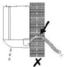

natural_image
Simple line drawing of a rectangular object with a small inset, connected by an arrow to a segmented rectangle (no text or symbols)natural_image
Technical line drawing of an internal electronic device with a cable extending into it (no text or symbols present)natural_image
Simple line drawing of a pipe with a submerged object and a vertical pole (no text or symbols)natural_image
Simple line drawing of a mechanical component with springs and bolts (no text or symbols)Drainageanschluss

Drainageschlauch
natural_image
Line drawing of a dual-panel air conditioner unit with fan blades and ventilation slots (no text or symbols)natural_image
Line drawing showing a device transitioning from a fan-shaped air conditioner to a multi-panel fan assembly (no text or symbols)natural_image
Line drawing of a smartphone with rounded corners and a horizontal bar (no text or symbols)
natural_image
Diagram of a battery pack assembly with arrows indicating components (no text or symbols)Función SELF-CLEAN
natural_image
Technical line drawing of a mechanical frame assembly with no visible text or symbolsNota:
natural_image
Illustration of two mechanical components: a threaded connector and a hand holding a cable (no text or symbols present)natural_image
Technical line drawing of an internal air conditioner unit with no visible text or symbolsPuertos de drenaje
natural_image
Diagram of a wall-mounted device connected to a brick wall, with a scroll partially visible (no text or symbols)
natural_image
Diagram showing a brick wall with a pipe flowing downward and a small container with an arrow pointing to it (no text or symbols present)

natural_image
Technical line drawing of an internal electronic device with a cable extending from it (no text or symbols present)natural_image
Diagram of a pipe with a granular material embedded in a channel, no text or symbols presentnatural_image
Line drawing of a multi-panel air conditioner unit with fan blades and cooling fins (no text or symbols)natural_image
Line drawing of a two-part industrial fan system with a hand inserting a fan into the front panel (no text or symbols)natural_image
Pure mechanical diagram showing a pipe joint with a valve and bolt, no text or symbols presentnatural_image
Line drawing of a smartphone with rounded corners and a horizontal bar (no text or symbols)

natural_image
Diagram of a battery pack assembly with arrows indicating components (no text or symbols)Função SELF-CLEAN
natural_image
Technical line drawing of a mechanical frame assembly with no visible text or symbolsNota:
Manga de parede (Opcional)
Exterior
5-10mm
natural_image
Technical illustration showing two mechanical components: a threaded bolt and a wire being inserted into a clamped tool (no text or symbols present)natural_image
Technical line drawing of a mechanical device interior showing internal components and mounting points (no text or symbols)Portas de drenagem
natural_image
Simple line drawing of a wall-mounted device next to a brick wall, with a scroll partially visible (no text or symbols)
natural_image
Diagram showing a pipe flowing from a brick wall to a container with an arrow indicating direction (no text or symbols)
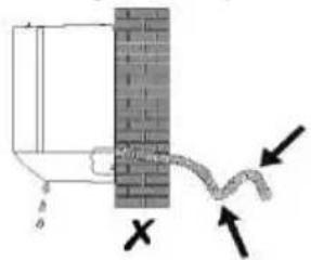
flowchart
graph LR
    A["Rectangular Block"] --> B["Arrow"]
    B --> C["Segmented Rectangle"]
natural_image
Technical line drawing of an internal electronic device with a cable extending from it (no text or symbols present)natural_image
Pure diagram of a pipe or tube with a circular object inserted, no text or symbols presentnatural_image
Technical line drawing of a mechanical assembly with no visible text or symbolsnatural_image
Line drawing of a rectangular air conditioner unit with a circular fan and mounting base (no text or symbols)Instale 4 cobertores de borracha
natural_image
Technical line drawing of a mechanical component or housing (no text or symbols)Diagramas de conexões
natural_image
Line drawing showing a fan installation process: before and after being added, with no text or symbols present.Retire a tampa da válvula
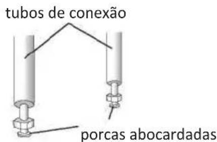
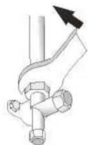
natural_image
Pure mechanical diagram of a pipe joint with a directional arrow (no text or symbols)INSTALLATIE BINNENUNIT 25
INSTALLATIE BUITENUNIT....35
WERKINGSTEST....38
ONDERHOUD....39
PROBOLEEMOPLOSSING....41
VERWIJDERING
natural_image
Line drawing of a smartphone with rounded corners and a horizontal scroll (no text or symbols)

SELF-CLEAN function
INSTALLATIE BINNENUNIT
INSTALLATIE BINNENUNIT
natural_image
Technical line drawing of a mechanical frame assembly with no visible text or symbolsN.B.:
INSTALLATIE BINNENUNIT
natural_image
Illustration of two types of mechanical components: a threaded bolt and a connector with a handle (no text or symbols)INSTALLATIE BINNENUNIT
natural_image
Technical line drawing of a mechanical device interior showing internal components and mounting points (no text or symbols)Drainagepoorten
INSTALLATIE BINNENUNIT
INSTALLATIE BINNENUNIT
natural_image
Technical line drawing of an internal electronic device with a cable extending from it (no text or symbols present)INSTALLATIE BINNENUNIT
Stap 8: Leidingen en kabels omwikkelen
natural_image
Diagram of a mechanical or electrical component with a U-shaped groove and textured base, embedded in a cylindrical shaft (no text or symbols)Stap 9: Binnenunit monteren
natural_image
Simple line drawing of a mechanical component with no text or symbolsDrainagekoppeling

Drainageslang
Stap 3: Buitenunit vastzetten
natural_image
Line drawing of a dual-panel air conditioner unit with fan blades and ventilation slots (no text or symbols)natural_image
Line drawing showing a fan installation process: before and after being added, with no text or symbols present.Neem eht klepdeksel weg
aansluitleidingen
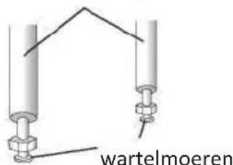
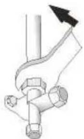
natural_image
Pure mechanical diagram of a pipe joint with a handle and valve (no text or symbols)INSTALLATIE BUITENUNIT
Stap 6: Vacuüm pompen
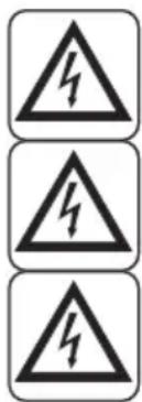
natural_image
Line drawing of a smartphone with rounded corners and a horizontal bar (no text or symbols)
natural_image
Diagram of a battery pack assembly with arrows indicating components (no text or symbols)flowchart
graph LR
    A["Icon"] --> B["Icon"]
    B --> C["Icon"]
    C --> D["Icon"]
    D --> E["Icon"]
    E --> F["Arrow"]
    F --> G["Arrow"]
    G --> H["Arrow"]
natural_image
Technical line drawing of a mechanical frame assembly with no visible text or symbolsΣημείωση:
natural_image
Illustration of a hand holding a tool or device with multiple lines extending outward (no text or symbols)natural_image
Technical line drawing of a mechanical device interior showing internal components and mounting points (no text or symbols)Θύρες αποστράγγισης
natural_image
Four-panel diagram showing a wall-mounted device with a cable and a small component, connected by arrows indicating movement or force (no text or symbols)flowchart
graph LR
    A["Initial State"] --> B["Step 1"]
    B --> C["Step 2"]
    C --> D["Final State"]
natural_image
Technical line drawing of an internal electronic device with a cable extending from it (no text or symbols present)natural_image
Simple line drawing of a pipe with a textured base and a vertical support (no text or symbols)natural_image
Line drawing of a front-end air conditioner unit with fan blades and cooling fins (no text or symbols)natural_image
Line drawing of a two-part HVAC system showing fan installation and cooling process (no text or symbols)natural_image
Pure mechanical diagram showing two vertical cylindrical components connected by a curved line, with no text or symbols present.παξιμάδια φλάντζας
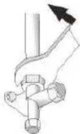
natural_image
Pure mechanical diagram showing a pipe joint with a valve and bolted connection (no text or symbols)natural_image
Line drawing of a smartphone with rounded corners and a horizontal screen (no text or symbols)

natural_image
Diagram of a device's internal components and assembly, showing a rectangular panel with a curved arrow indicating rotation (no text or symbols present)natural_image
Simple diagram with five circles arranged horizontally and a right-pointing arrow below (no text or symbols)Złe Dobre
natural_image
Technical line drawing of a mechanical frame assembly with no visible text or symbolsZanotuj:
natural_image
Illustration of two types of electrical connectors: a threaded connector and a wire-wrapped cable with wires (no text or symbols)natural_image
Technical line drawing of a mechanical device interior showing internal components and mounting points (no text or symbols)Porty spustowe
natural_image
Simple line drawing of a wall-mounted device next to a brick wall, with a checkmark indicating a detail (no text or symbols present)
natural_image
Diagram showing a pipe flowing from a brick wall to a container with an arrow indicating direction (no text or symbols)
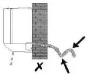
natural_image
Technical line drawing of an internal electronic device with a cable extending from it (no text or symbols present)natural_image
Pure diagram of a mechanical or electrical component with no visible text, numbers, or symbolsnatural_image
Diagram showing a hand inserting a fan into a device, then to add a separate fan into a final panel (no text or symbols present)natural_image
Diagram of a mechanical assembly with two vertical rods and a central bracket, labeled 'nakre' at the bottom (no other text or symbols)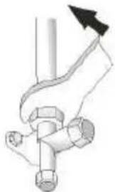
natural_image
Diagram of a hand holding a pipe fitting with a valve and bolt (no text or symbols)natural_image
Line drawing of a smartphone with rounded corners and a horizontal bar (no text or symbols)
natural_image
Diagram of a battery pack assembly with arrows indicating components (no text or symbols)natural_image
Technical line drawing of a mechanical frame assembly with no visible text or symbolsNotă:
natural_image
Diagram showing two types of electrical connectors: a threaded connector and a wire-wound plug (no text or symbols present)INSTALARE UNITATE INTERNĂ
Pasul 5: Conectare furtun de drenaj
natural_image
Technical line drawing of a mechanical device interior showing internal components and structural layout (no text or symbols)Orificii drenaj
natural_image
Simple line drawing of a wall-mounted device next to a brick wall, with a scroll partially visible (no text or symbols)
natural_image
Diagram showing a brick wall with a pipe and a container, no text or symbols present

Pasul 6: Conectare cablaj
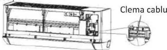
INSTALARE UNITATE INTERNĂ
natural_image
Simple line drawing of a rectangular object with an arrow pointing to a segmented rectangle (no text or symbols)natural_image
Technical line drawing of an internal electronic device with a cable extending from it (no text or symbols present)natural_image
Pure diagram of a mechanical or electrical component with no visible text, numbers, or symbolsINSTALARE UNITATE INTERNĂ
natural_image
Line drawing of a mechanical component with springs and connectors (no text or symbols)Manşon drenaj
Furtun de drenaj
natural_image
Line drawing of a dual-panel air conditioner unit with fan blades and ventilation slots (no text or symbols)natural_image
Line drawing of a two-part HVAC system showing fan installation and cooling process (no text or symbols)natural_image
Pure mechanical diagram showing two vertical rods connected by a curved bracket, with no text or symbols present.piulite evazate
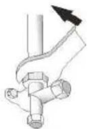
natural_image
Diagram of a hand holding a pipe fitting with a directional arrow indicating force or movement (no text or symbols present)INSTALARE UNITATE EXTERNĂ
OLIMPIA SPLENDID spa
via Industriale 1/3
25060 Cellatica (BS)
www.olimpiasplendid.it
info@olimpiasplendid.it
- INSTALLAZIONE DELL'UNITÀ INTERNA
- DISPOSAL
- - SYMBOLS
- Index
- HAZARD
- GENERIC DANGER
- - GENERAL WARNINGS
- - NOTES REGARDING FLUORINATED GASES
- - PROPER USE
- - HAZARDOUS ZONES
- - CHECKS TO PERFORM BEFORE INSTALLATION
- a. Checks at the area
- b. Work procedure
- c. General work area
- d. Check the presence of refrigerant
- e. Presence of extinguishers
- f. No source of ignition
- g. Ventilated area
- h. Refrigeration system checks
- i. Check the electric devices
- Repair interventions of the hermetic components
- Indoor Unit
- Outdoor Unit
- Indoor Display
- Note:
- Replacement of Batteries
- COOLING MODE
- COOL
- FAN MODE (Not FAN button)
- FAN
- DRY MODE
- DRY
- AUTO MODE
- AUTO
- HEATING MODE
- HEAT
- (For North American market)
- FAN SPEED function (FAN button)
- Child-Lock function
- TIMER function ---- TIMER ON
- TIMER
- TIMER function ----TIMER OFF
- SWING function
- TURBO function
- TURBO
- REMOTE CONTROL
- MUTE function
- MUTE
- ECO function
- SLEEP function
- I FEEL function
- DISPLAY function (Indoor display)
- GEN function (energy saving)
- Reset Wi-Fi
- SELF-CLEAN function
- 8°C heating function
- Gentle Wind function
- Fresh Air function
- TVOC function
- OPERATION INSTRUCTIONS
- Characteristics of heating operation (applicable to Heating pump)
- Preheating:
- Defrosting:
- INSTALLATION PRECAUTIONS
- INDOOR UNIT INSTALLATION
- Step1: Select Installation location
- Step2: Install Mounting Plate
- Step3: Drill Wall Holes
- Caution:
- Step4: Connecting Refrigerant Pipe
- Step5: Connect Drainage Hose
- Adjust the drainage hose(if applicable)
- Step6: Connect Wiring
- Step7: Connecting Fresh Air Pipe and place the filter
- Adjusting the length of the fresh air pipe assembly
- Shorten the length
- Increase the length
- Step8: Wrap Piping and Cable
- Mode1
- Mode2
- Step9: Mount Indoor Unit
- OUTDOOR UNIT INSTALLATION
- Step2: Install Drainage Hose
- Step3: Fix Outdoor Unit
- Step4: Install Wiring
- Step5: Connecting Refrigerant Pipe
- Step6: Vacuum Pumping
- Inspections Before Test Run
- Test Run Instruction
- TEST OPERATION
- MAINTENANCE
- ERROR CODE ON THE DISPLAY
- ÉLEMINATION
- Note :
- Attention :
- INSTALLATION DE L'UNITÉ INTÉRIEURE
- INSTALLATION DE L'UNITÉ EXTÉRIEURE
- Kindersicherung
- INSTALLATION DES INNENRAUMGERÄTS
- Función SELF-CLEAN
- Nota:
- Função SELF-CLEAN
- VERWIJDERING
- INSTALLATIE BINNENUNIT
- N.B.:
- Stap 8: Leidingen en kabels omwikkelen
- Stap 9: Binnenunit monteren
- Stap 3: Buitenunit vastzetten
- INSTALLATIE BUITENUNIT
- Stap 6: Vacuüm pompen
- Σημείωση:
- Złe Dobre
- Zanotuj:
- Notă:
- INSTALARE UNITATE INTERNĂ
- Pasul 5: Conectare furtun de drenaj
- Pasul 6: Conectare cablaj
- INSTALARE UNITATE EXTERNĂ
Brand : OLIMPIA SPLENDID
Model : Alysea E
Category : Air Conditioning