
DE7260 - Saw support DEWALT - Free user manual and instructions
Find the device manual for free DE7260 DEWALT in PDF.

User questions about DE7260 DEWALT
0 question about this device. Answer the ones you know or ask your own.
Ask a new question about this device
Download the instructions for your Saw support in PDF format for free! Find your manual DE7260 - DEWALT and take your electronic device back in hand. On this page are published all the documents necessary for the use of your device. DE7260 by DEWALT.
USER MANUAL DE7260 DEWALT
English (original instructions) 16
Fig. F
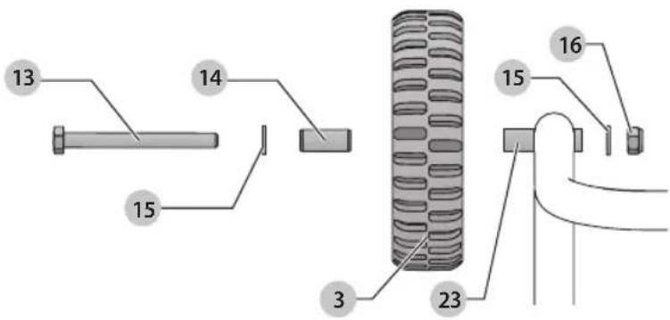
Fig. G
natural_image
Technical line drawing of a vehicle chassis frame with wheels and suspension components (no text or labels)Fig. H
natural_image
Technical line drawing of a wheeled cart or trailer mechanism with wheels and structural components (no text or symbols)Fig.1
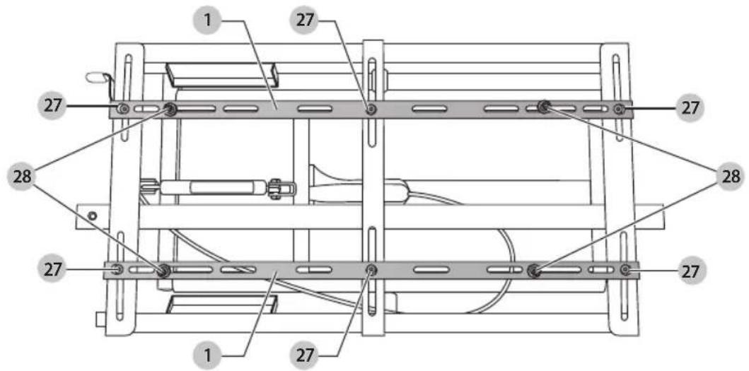
Fig. J Fig. K
natural_image
Top-down schematic of a vehicle chassis showing internal components and directional arrows (no text or labels)Fig. L
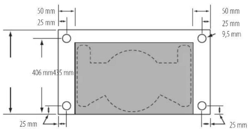
Fig. M
natural_image
Technical line drawing of a mechanical pump assembly with wheels and internal components (no text or symbols)Fig. N
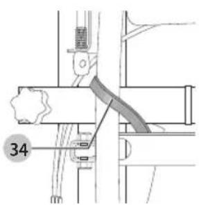
Fig. O Fig. P
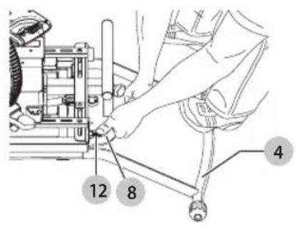
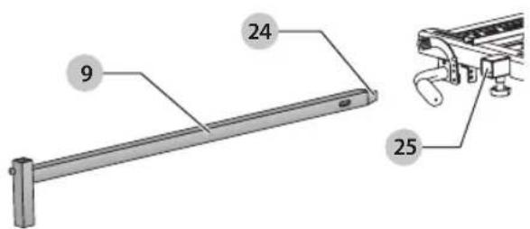
Fig. Q Fig. R
natural_image
Technical line drawing of a mechanical device with hands operating it (no text or symbols present)Fig. S
natural_image
Technical line drawing of a mechanical device with hands operating it (no text or symbols present)Fig. T
natural_image
Technical line drawing of a mechanical assembly with gears and housing (no text or symbols)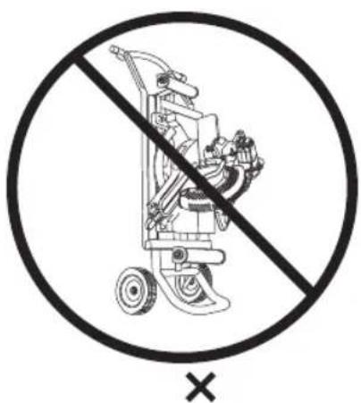
RULLESTATIV TIL GERINGSAV
DE7260
Tillykke!
You have chosen a DEWALT tool. Years of experience, thorough product development and innovation make DEWALT one of the most reliable partners for professional power tool users.
Technical Data
| DE7260 | |
| Maximum working load kg 136 | |
| Width (Extended) mm 2469 | |
| Width (Folded) mm 1488 | |
| Height (Extended) mm 813 | |
| Height (Folded) mm 419 | |
| Weight kg 27.7 | |
EC-Declaration of Conformity
Machinery Directive

Rolling Mitre Saw Stand DE7260
DEWALT declares that these products described under
Technical Data are in compliance with:
2006/42/EC, EN ISO 12100: 2010.
For more information, please contact DEWALT at the following address or refer to the back of the manual.
The undersigned is responsible for compilation of the technical file and makes this declaration on behalf of DEWALT.

Markus Rompel
Director Engineering
D-65510, Idstein, Germany
22.12.2017

WARNING: To reduce the risk of injury, read the instruction manual.
Definitions: Safety Guidelines
The definitions below describe the level of severity for each signal word. Please read the manual and pay attention to these symbols.
DANGER: Indicates an imminently hazardous situation which, if not avoided, will result in death or serious injury.
WARNING: Indicates a potentially hazardous situation which, if not avoided, could result in death or serious injury.
CAUTION: Indicates a potentially hazardous situation which, if not avoided, may result in minor or moderate injury.
NOTICE: Indicates a practice not related to personal injury which, if not avoided, may result in property damage.
Dr. notes risk of electric shock.
Diabetes risk of fire.
General Safety Warnings
WARNING: Read all safety warnings and all instructions of the rolling mitre saw stand and the mounted mitre saw. Failure to follow the warnings and instructions may result in electric shock, fire and/or serious injury.
SAVE ALL WARNINGS AND INSTRUCTIONS FOR FUTURE REFERENCE
Safety Rules
WARNING: For your own safety, read the tool instruction manual before using any accessory. Failure to heed these warnings may result in personal injury and serious damage to the tool and the accessory. When servicing this tool, use only identical replacement parts.
WARNING: Failure to follow these rules may result in serious personal injury.
WARNING: To reduce the risk of injury, keep both hands on handle when raising and lowering the stand. The stand has gas assist lifting and may raise unexpectedly when lever is released.
WARNING: Do not open or repair anything at the gas pressure spring. High pressure inside; risk of personal injury.
- Keep work area clean and well lit. Cluttered or dark areas invite accidents.
• Always have the rolling mitre saw stand serviced by a qualified repair person using only identical replacement parts. This will ensure that the safety is maintained.
- This product was designed to be used as a stand for mitre saws. The stand will support up to 136 kg. Any misuse or abuse can result in product damage or personal injury.
- Do not stand on the work table. It is unsafe to climb, sit or stand on the stand. Do not use the support extensions as a ladder or scaffolding.
- Properly secure the mitre saw to the stand before operation. Follow the mounting instructions carefully. Fasten the tool to the saw mounting rails securely as instructed.
- Place the stand on a flat and level surface to prevent rocking or tipping.
• Take care during the raising and lowering of the product to reduce the hazard of pinching hands and fingers. - Check the legs and other supports to see that they are properly locked in place before operation.
- Do not modify or use the stand for any operation for which it is not intended.
- If protection or adjustment device or weld is damaged, no longer use this rolling mitre saw stand.
Package Contents
The package contains:
2 Mounting rails
1 Foot
2 Wheels
1 Leg extension
1 Hex wrench
1 Vertical lock knobs
1 Horizontal lock knobs
1 Handle
1 Work support extension arm
1 Work support
1 Stop plate
1 Activating lever
Hardware bag 1:
2 Axles
2 Bushings
4 Washers
2 Nuts
Hardware bag 2:
4 M8 x 16 mm button head screws
4 Curved washers
1 M6 x 10 mm button head screw
1 M6 lock washer
1 M8 x 21 mm button head screw with thread locking patch
1 M8 lock washer
1 Instruction manual
- Check for damage to the tool, parts or accessories which may have occurred during transport.
• Take the time to thoroughly read and understand this manual prior to operation.
Markings on Tool
The following pictograms are shown on the tool:

Read instruction manual before use.

Do not cut packaging contents.

Pinch and Impact Hazard.
Date Code Position (Fig. B)
The date code 33 which also includes the year of manufacture, is printed into the housing.
Example:
2017 XX XX
Year of Manufacture
Description (Fig. A)
WARNING: Never modify the power tool or any part of it. Damage or personal injury could result.
1 Mounting rails
2 Foot
3 Wheels
4 Leg extension
5 Hex wrench
6 Vertical lock knobs
7 Horizontal lock knobs
8 Handle
9 Work support extension arm
10 Work support
11 Stop plate
12 Activating lever
13 Axles
14 Bushings
15 Washers
16 Nuts
17 M8 x 16 mm button head screws
18 Curved washers
19 M6 x 10 mm button head screw
20 M6 lock washer
21 M8 x 21 mm button head screw with thread locking patch
22 M8 lock washer
Intended Use
This rolling mitre saw stand is designed for use with DEWALT mitre saws. If you have any problem with alignment or mounting, consult an authorised DEWALT repair agent.
DO NOT use under wet conditions or in the presence of flammable liquids or gases.
DO NOT let children come into contact with the tool. Supervision is required when inexperienced operators use this tool.
DO NOT transport persons or other loads with the ROLLING MITRE SAW STAND.
- Young children and the infirm. This appliance is not intended for use by young children or infirm persons without supervision.
- This product is not intended for use by persons (including children) suffering from diminished physical, sensory or mental abilities; lack of experience, knowledge or skills unless they are supervised by a person responsible for their safety. Children should never be left alone with this product.
ASSEMBLY AND ADJUSTMENTS

WARNING: Pinch and impact hazard. Do not cut the large securing cable ties (34 Fig. B) until instructed to do so later in the manual. The spring loaded mechanism is under tension and can open unexpectedly, with high force. To reduce the risk of serious personal injury, do not raise or lower stand until the assembly is complete.
Tools Required for Assembly (Fig. A)
- Hex wrench 5 (supplied, comes in the wrench storage location in the corner of the stand)
- Adjustable wrench
- 13 mm open end wrench
- 18 mm open end wrench
- Wire cutting pliers
NOTE: This rolling mitre saw stand is a stand designed to accommodate most mitre saws and to provide portability for those units, both in the field and in the shop.
Wrench Storage (Fig. A)
The supplied hex wrench 5 comes in the wrench storage location in the corner of the stand.
Attaching the Leg Extension (Fig. B, C)
IMPORTANT: Place stand upside down on the floor or on a level, stable table as shown in Figure B.
- With stand upside down, insert the leg extension 4 in the stand.
- Align the holes and install two M8 x 16 mm button head screws 17 with curved washers 18.
- Tighten securely with the supplied hex wrench 5.
Attaching the Storage Foot to Stand (Fig. D)
- With the stand upside down, lift the end opposite the leg extension and insert the storage foot 2 into the stand with the u-shape tube upside down.
- Align the holes and install one M8 x 16 mm button head screw 17 with one curved washer 18 on each side.
- Tighten securely with the supplied hex wrench 5.
Attaching the Handle (Fig. E)
- With stand upside down, attach the handle 8 on the end of the stand opposite the wheels with one M8 x 21 mm button head screw 21 and lock washer 22. Install screw using supplied hex wrench, but do not tighten securely.
- Turn the stand right side up so the wheels and leg extension sit level on the floor or stable table. Ensure the stand remains in the closed position, do not raise the stand.
- Install one M6 x 10 mm button head screw 19 and lock washer 20 on the other side. Tighten securely with the supplied hex wrench.
- Tighten M8 x 21 mm button head screw 21 added in STEP 1 securely with the supplied hex wrench.
Attaching the Wheels (Fig. F, G)
- Slide a washer 15 and bushing 14 on to the axle bolt 13.
- Continuing with stand upside down, insert the axle bolt into the wheel 3 and the wheel extension 23 on the frame as shown in Figure F. NOTE: Ensure the ribbed side of wheel hub is facing inward toward the frame assembly.
- Place a washer 15 and locking nut 16 on the threaded end of the axel bolt.
- Tighten the axle bolt and nut using a 13 mm wrench and an adjustable wrench.
NOTE: Do not overtighten. Overtightening may cause wheel rotation to be impaired. - Attach the other wheel in the same manner.
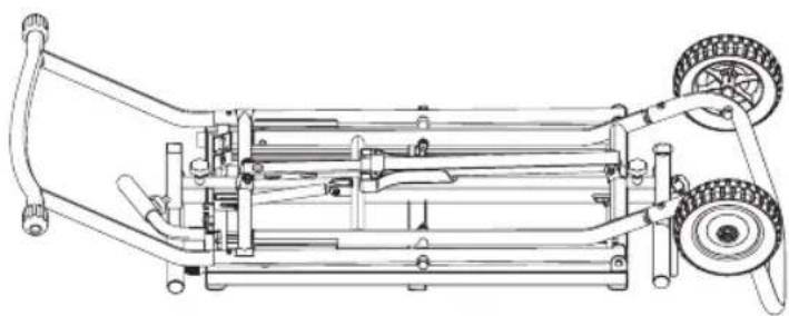
To Raise and Lower the Stand (Fig. A, H, N–0)
WARNING: PINCH AND IMPACT HAZARD. The spring loaded mechanism is under tension and can open unexpectedly, with high force.
- Turn the stand right side up on the floor.
IMPORTANT: Stand must be right side up when cutting white cable ties 34. -
While holding down on the top of the stand frame, use wire cutting pliers to cut the white cable ties.
IMPORTANT: DO NOT cut the black cable ties securing the cables that open the stand. -
Place one foot on the bottom of the leg extension 4. Hold the handle down with one hand, push the red activating lever 12 to disengage the latching mechanism.
-
Lift the handle 8 with both hands while simultaneously pushing the red lever.
The Stand Has Three Positions: Closed, Fully Extended and Intermediate
To Reach the Intermediate Position
Lift up on the handle and slowly raise the stand. The stand will stop at the intermediate position. Release the lever.
NOTE: When in the intermediate position, the stand will lower slightly when a tool is placed on it. The intermediate position does not lock against upward motion. The stand relies on the weight of the tool to remain in the intermediate position.
To Fully Extend Stand
Start in the intermediate position. Repeat STEPS 3–4. Lift up on the handle and raise the stand to the fully extended position. The stand will latch in the fully extended position. Release the lever.
To Close Stand
Repeat STEPS 3–4. You must lift up on the handle and then push down until the stand is closed. Release the lever.
IMPORTANT: Lift the handle first to disengage latch before able to lower stand.
Attaching the Extension Arms and Work Supports (Fig. A, P, Q)
IMPORTANT: Be sure the longer side of the "T" in the work support arm 9 is oriented down as shown in Figure P. Ensure the arrow on the label points down.
- Insert the long work support arm with the small black cap (24, Fig. P) into the hole 25 of the stand closest to the red activating lever. Push the arm in to snap in place.
- Repeat for other work support arm on opposite end. Push the arm in to snap in place. Tighten the horizontal locking knobs to secure.
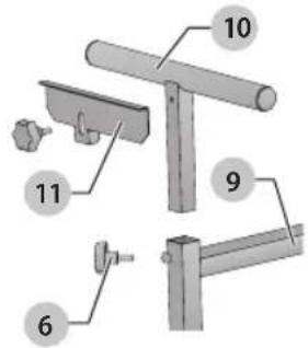
- With the stand raised to desired height, insert the work support 10 into the top of the extension arm 9 hole. The threaded hole in the work support should be facing outward.
- Insert the vertical locking knob 6 into the side hole of the work support arm. Tighten the vertical lock knob 6.
- Repeat with the other work support.
NOTE: The internal locking mechanism keeps the work support arm from disengaging.
Attaching the Stop Plate
- Align the slot in the stopping plate 11 with the outward facing threaded hole of the work support 10.
NOTE: The stopping plate can be attached to either work support. - Secure the stop plate to work support by installing and tightening knob shown in Figure Q.
Attaching the Tool (Fig. A, H–M)
WARNING: STABILITY HAZARD. Refer to your tool manufacturer's instructions regarding the securing of your mitre saw to a stand or supporting surface. Secure the tool according to both the instructions in this manual and those in your tool manufacturer's manual before operating. Failure to heed these warnings may result in serious personal injury and serious damage to the tool.
- Turn the stand right side up and leave stand in closed position before attaching the saw.
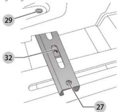
- Loosen the 6 rail screws 27 with the supplied hex wrench. Remove the four mounting bolts/flat washers 28 from the mounting rails 1.
- Slide the mounting rails 1 to fit the width of the tool.
- Place mitre saw on the mounting rails 1. Centre the tool, both forward and backward and side to side, on the stand (Fig. K).
- Ensure the mounting holes 29 in the tool's feet align with the rail (Fig. J).
- Insert the mounting bolts/flat washers 28 (removed in STEP 2) through each of the tool's feet into the captured nut 32. Tighten securely.
- Once the saw is tight to the rails, tighten the rail screws 27 loosened in STEP 2.
If Your Saw Does Not Readily Fit the Mounting Rails
IMPORTANT: The mitre saw MUST be positioned so the tool is bolted squarely to the mounting rails.
WARNING: STABILITY HAZARD. If the tool's mounting holes do not line up with the slots in the mounting rails, mount the mitre saw to a piece of 19 mm plywood (See Figure L for dimensions). The plywood must be a minimum of 102 mm wider than the tool base being mounted and a minimum depth of 435 mm. Plywood must be at least as deep as the tool base being mounted. Drill 9.5 mm holes near both ends of the plywood to align with the slots in the mounting rails as described in Attaching the Tool. Other hardware (not supplied) may be necessary under these circumstances.
WARNING: STABILITY HAZARD. All purchased hardware must be a minimum of Grade 2. Hardware should be 31.8 mm longer than the thickness of the tool base you are assembling.
NOTICE: To prevent binding and/or inaccuracy, ensure the plywood is not warped or uneven. If binding and/or inaccuracy occurs, replace the plywood with a non-warped, even piece of plywood.
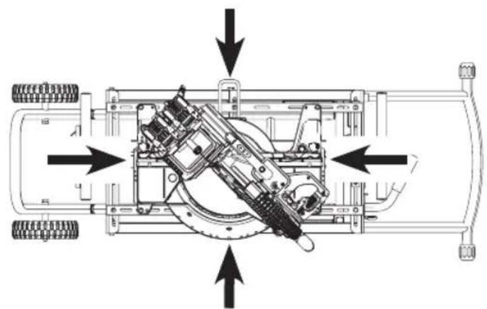
Product Stability Test (Fig. I, R, S)
IMPORTANT: This test must be performed prior to using stand and saw together.
The rolling mitre saw stand is designed to be used in conjunction with a wide variety of mitre saws, compound mitre saws and sliding compound mitre saws.
WARNING: For your own safety, use two or more people to perform the stability test or serious injury could result. WARNING: The cutting head MUST be raised on all litre saws, compound mitre saws and sliding compound mitre saws. All sliding compound mitre saws MUST be locked in the rear position. Failure to do so may result in serious personal injury. WARNING: STABILITY HAZARD. Stay alert. The suit may tip during this procedure. Serious injury may result.
- With one person in front of saw/stand and one person in back of saw/stand, both ready to catch saw, the person in front lifts the front legs approximately 65 mm and then lets it go, dropping it. Does stand tend to tip over toward front? If so, re-adjust saw further back on stand and retighten fasteners.
- The person in back lifts rear legs approximately 65 mm and drops it. Does stand tend to tip over toward back? If so, readjust saw toward front of stand and retighten fasteners 27.
OPERATION
Instructions for Use
WARNING: To reduce the risk of injury. After completing assembly and before each use, ensure all bolts and nuts are properly tightened and all mechanisms operate properly.
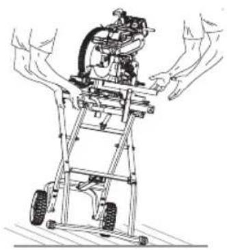
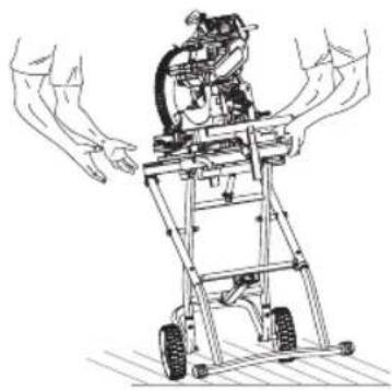
WARNING: To reduce the risk of injury, keep both hands on handle and the right foot on the extension leg when raising and lowering the stand. The stand has gas assist lifting and may raise unexpectedly when lever is released.
WARNING: To reduce the risk of personal injury, never release the activating lever when the rolling mitre saw stand is in vertical position (Fig. T). The spring loaded mechanism is under tension and can open unexpectedly, with high force.
Refer to To Raise and Lower the Stand under Assembly to adjust the stand to the desired height.
To Extend the Extension Work Supports (Fig. A)
- Turn the horizontal lock knob 7 counterclockwise.
- Slide the work support extension arm 9 out or in, depending on the length of the workpiece.
- Tighten the horizontal lock knob.
- Repeat with the other side.
To Adjust Extension Work Support Height (Fig. A)
- Turn the vertical lock knob 6.
- Adjust the work support 10 up or down to the desired height.
- Tighten the vertical lock knob.
- Repeat with the other extension work support.
To Use the Stop Plate (Fig. A)
The rolling mitre saw stand equip with the stop plate 11. Please use the stop plate, if continuous cutting operation necessary.
- Loosen the stop plate lock knob to rotate the stop plate into a vertical position.
- Tighten the stop plate lock knob.
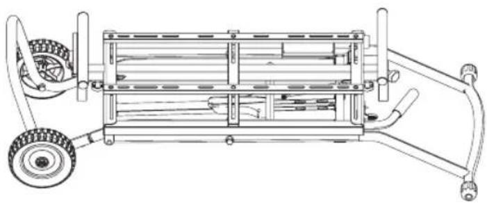
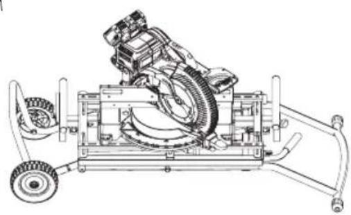
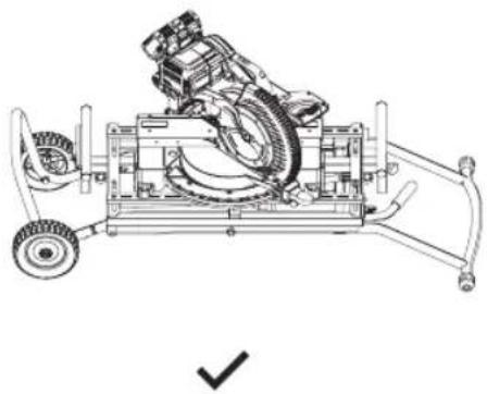
STORAGE AND TRANSPORTATION (Fig. T)
WARNING: TIPPING HAZARD. The stand may tip with storing or transporting the stand close to or in the vertical position. Transport or store the stand in the horizontal position to reduce the risk of the stand tipping.
To lower the stand into the storage position, push down on the red activating lever, lift up on the handle, then exert downward pressure on the handle.
Refer to Figure T for proper transporting position.
MAINTENANCE
Your DEWALT rolling mitre saw stand has been designed to operate over a long period of time with a minimum of maintenance. Continuous satisfactory operation depends upon proper tool care and regular cleaning.

Lubrication
Your power tool requires no additional lubrication.

Cleaning
WARNING: Blow dirt and dust out of the main housing industry dry air as often as dirt is seen collecting in and around the air vents. Wear approved eye protection and approved dust mask when performing this procedure.
WARNING: Never use solvents or other harsh chemicals for cleaning the non-metallic parts of the tool. These chemicals may weaken the materials used in these parts. Use a cloth dampened only with water and mild soap. Never let any liquid get inside the tool; never immerse any part of the tool into a liquid.
Optional Accessories
WARNING: Since accessories, other than those offered by DEWALT, have not been tested with this product, use of such accessories with this tool could be hazardous. To reduce the risk of injury, only DEWALT recommended accessories should be used with this product.
The rolling mitre saw stand is designed to be used in conjunction with a wide variety of DEWALT mitre saws, compound mitre saws and sliding compound mitre saws.
BEWAAR ALLE WAARSCHUWINGEN EN INSTRUCTIES ALS TOEKOMSTIG REFERENTIEMATERIAAL
Director de Engenharia
Fixar as rodas (Fig. F, G)
D-65510, Idstein, Germany
22.12.2017
