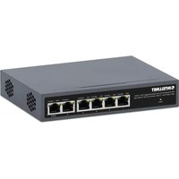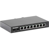
508827 - Switch Intellinet - Free user manual and instructions
Find the device manual for free 508827 Intellinet in PDF.




User questions about 508827 Intellinet
0 question about this device. Answer the ones you know or ask your own.
Ask a new question about this device
Download the instructions for your Switch in PDF format for free! Find your manual 508827 - Intellinet and take your electronic device back in hand. On this page are published all the documents necessary for the use of your device. 508827 by Intellinet.
USER MANUAL 508827 Intellinet
with 2 SFP Ports Instructions
Model 508827 (IIS-8G02)

text_image
INTELLINET® NETWORK SOLUTIONSImportant: Read before use. • Importante: Leer antes de usar.
natural_image
Exterior view of a Siemens SFP2 network switch with multiple Ethernet ports (no signage or text beyond branding)For additional benefits:
Scan to register your product warranty

text_image
QR code image containing encoded data, no visible human-readable textor go to: register.intellinet-network.com/r/508827
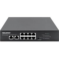
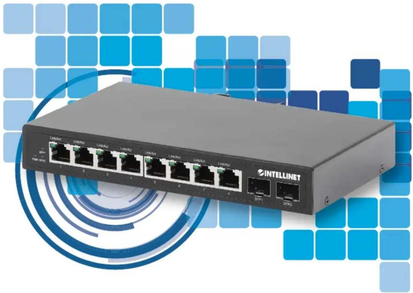
The Intellinet 8-Port Gigabit Ethernet Industrial Switch with 2 SFP Ports offers an array of time-saving, cost-effective features while providing superior network throughput. No configuration is required and installation is plug and play.
Features
- Provides RJ45 data connections for up to eight network devices
- IP40 slim-type metal housing to withstand harsh industrial conditions
- Wide operating temperature: -40 – 75°C (-40 – 167°F)
- Option for DIN-rail installation
- Two small form-factor pluggable GBIC module slots (SFP)
- Two redundant DC inputs (12 – 48 V) with I/O terminal block
With a backplane speed of 20 Gbps, plenty of performance is available for your computers, servers and other networking devices. Each of the ports automatically senses the link speed of the connected network device and adjusts to 10, 100 or 1000 Mbps for compatibility and maximum performance.
For specifications, visit intellinetnetwork.com. Register your product at register.intellinet-network.com/r/508827 or scan the QR code on the cover.

LEDs

text_image
SFP1 PWR SFP2 1 2 3 4 5 6 7 8 INTELLINET SFP1 SFP2LED Color Status Status Description
| PWR Green | On Power on | ||
| Off Power off | |||
| Link/Act1 – 8 /SFP1 & 2 | Green | On Valid port | connection |
| Blinking Sending | or receiving data | ||
| Off No link established | |||
Cat5e/6/6a UTP/STP cables provide optimal performance; if a status LED doesn't indicate a link or activity, check the corresponding device for proper setup and operation.

Power
Chassis Ground Column
Located on the side of the power supply connector, a grounding terminal connector is used to provide proper grounding for your Intellinet Network Solutions switch. It should be wired to an object that provides earth ground.
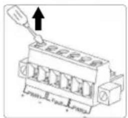
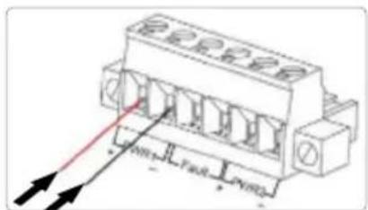
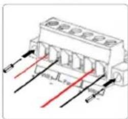
Terminal Block Installation
NOTE: Ensure all power is off/disconnected before beginning!
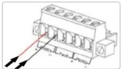
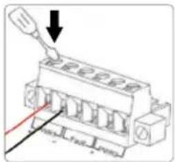
1 Loosen appropriate screws.
2 Insert bare power-supply wires into appropriate terminal slots (positive wire into positive slot; negative wire into negative slot).
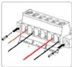
3 Tighten appropriate screws to secure wires. (If desired, repeat steps 1 – 3 on second input pair.)
4 Install block into the device and tighten screws.
1
text_image
Diagram of a fuse or socket component with labeled pins and an upward arrow indicating directionThe image is too blurry to recognize any text content.
text_image
Technical diagram of a terminal connector with labeled pins and directional arrows indicating connection points.[Non-Text]
text_image
Diagram showing a connector with labeled pins and an arrow indicating direction, likely from an electrical or mechanical assembly context.[Non-Text]
text_image
Technical diagram of a connector with labeled pins and red arrows indicating direction or flowPower Off Alarm
You can choose whether to connect the power failure warning device to the connecting terminal marked "Fault" according to your requirements. When using power redundancy, if one power source fails, a fault alarm will be generated.

Placement
Desktop Installation
Prior to use, place/position the switch:
- on a level surface that can support the weight of the switch and that offers at least 25 mm (approx. 1") of clearance for ventilation;
- away from sources of electrical noise: radios, transmitters, broadband amplifiers;
- within 100 m (approx. 328') of network devices it's to be connected to;
• where it cannot be affected by excessive moisture.
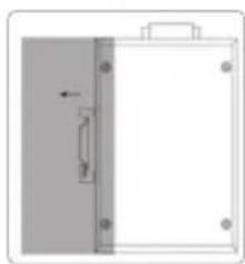
DIN-Rail Installation
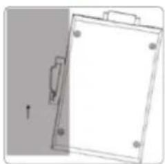
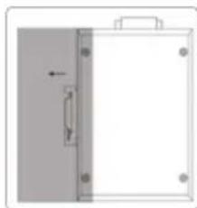
1 With DIN-rail bracket attached to device with screws, angle bracket onto DIN rail.
2 Push device in till it clicks into place.
1
natural_image
Simple line drawing of a rectangular object with mounting holes and a handle, no text or symbols present.2
natural_image
Pure diagram of a door or cabinet with no text, numbers, or symbolstext_image
Diagram showing four steps of a terminal connector with labeled pins and directional arrows indicating assembly or connection.natural_image
Diagram showing a blank clipboard with a handle and an arrow, no text or symbols present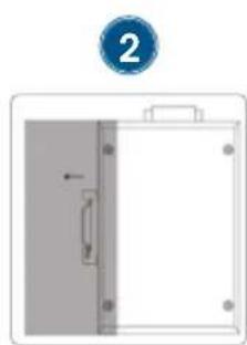
natural_image
Simple diagram of a door with a handle and arrow, no text or symbols presenttext_image
Technical diagram of a fuse or connector with labeled pins and an arrow indicating direction[Non-Text]
text_image
Technical diagram of a connector with labeled pins and directional arrows indicating assembly or connection points.[Non-Text]

text_image
Technical diagram of a fuse or terminal block with labeled pins and an arrow indicating direction[Non-Text]
text_image
Technical diagram of a mechanical or electrical component with labeled ports and directional arrows indicating flow or movement.natural_image
Simple line drawing of a blank rectangular object with a handle and corner markers, no text or symbols present.2
natural_image
Simple diagram of a white rectangular object with a gray vertical panel and a black arrow indicating leftward movement (no text or symbols)text_image
Diagram showing four steps of a fuse terminal connector assembly with labeled arrows and connection pointsnatural_image
Diagram showing a door panel with a blue circular indicator labeled '1' pointing to the left side (no text or symbols on the door itself)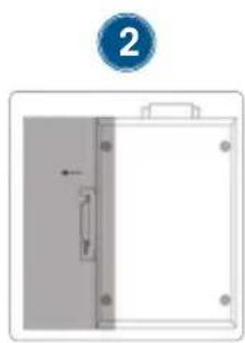
natural_image
Simple diagram of a door with a handle and arrow, no text or symbols presentnatural_image
Diagram showing a door panel with an arrow pointing to the left side, no text or symbols present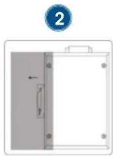
natural_image
Simple diagram showing a vertical arrow inside a rectangular frame with a circular label containing the number 2 (no text or symbols on the diagram itself)natural_image
Diagram showing a white rectangular object with four corner holes and a blue circular marker labeled '1' pointing to it (no text or symbols on the object itself)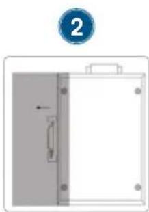
natural_image
Diagram of a door handle with a blue circular indicator labeled '2' pointing to the left side (no text or symbols on the door itself)WASTE ELECTRICAL & ELECTRONIC EQUIPMENT
DISPOSAL OF ELECTRIC AND ELECTRONIC EQUIPMENT
(Applicable In The European Union And Other European Countries With Separate Collection Systems)
ENGLISH: This symbol on the product or its

packaging means that this product must not be treated as unsorted household waste. In accordance with EU Directive 2012/19/EU on Waste Electrical and Electronic Equipment (WEEE), this electrical product must be disposed of in accordance with the user's local regulations for electrical or electronic waste. Please dispose of this product by returning it to your local point of sale or recycling pickup point in your municipality.
This equipment has been tested and found to comply with the limits for a Class A digital device, pursuant to Part 15 of the Federal Communications Commission (FCC) Rules. These limits are designed to provide reasonable protection against harmful interference when the equipment is operated in a commercial environment. This equipment generates, uses and can radiate radio frequency energy, and if not installed and used in accordance with the instruction manual may cause harmful interference to radio communications. Operation of this equipment in a residential area is likely to cause harmful interference, in which case the user will be required to correct the interference at his own expense. Any changes or modifications made to this equipment without the approval of the manufacturer could result in the product not meeting the Class A limits, in which case the FCC could void the user's authority to operate the equipment.
CE
ENGLISH: This device complies with the requirements of CE 2014/30/EU and / or 2014/35/EU. The Declaration of Conformity for is available at:
support.intellinet-network.com/barcode/508827



North America
IC Intracom America
550 Commerce Blvd.
Oldsmar, FL 34677, USA
Asia & Africa
IC Intracom Asia
4-F, No. 77, Sec. 1, Xintai 5th Rd.
Xizhi Dist., New Taipei City 221, Taiwan
Europe
IC Intracom Europe
Löhbacher Str. 7, D-58553
Halver, Germany

text_image
INTELLINET® NETWORK SOLUTIONSintellinetnetwork.com
All trademarks and trade names are the property of their respective owners.
© IC Intracom. All rights reserved. Intellinet Network Solutions is a trademark of IC Intracom, registered in the U.S. and other countries.