562102 - Network card / adapter Intellinet - Free user manual and instructions
Find the device manual for free 562102 Intellinet in PDF.



User questions about 562102 Intellinet
0 question about this device. Answer the ones you know or ask your own.
Ask a new question about this device
Download the instructions for your Network card / adapter in PDF format for free! Find your manual 562102 - Intellinet and take your electronic device back in hand. On this page are published all the documents necessary for the use of your device. 562102 by Intellinet.
USER MANUAL 562102 Intellinet
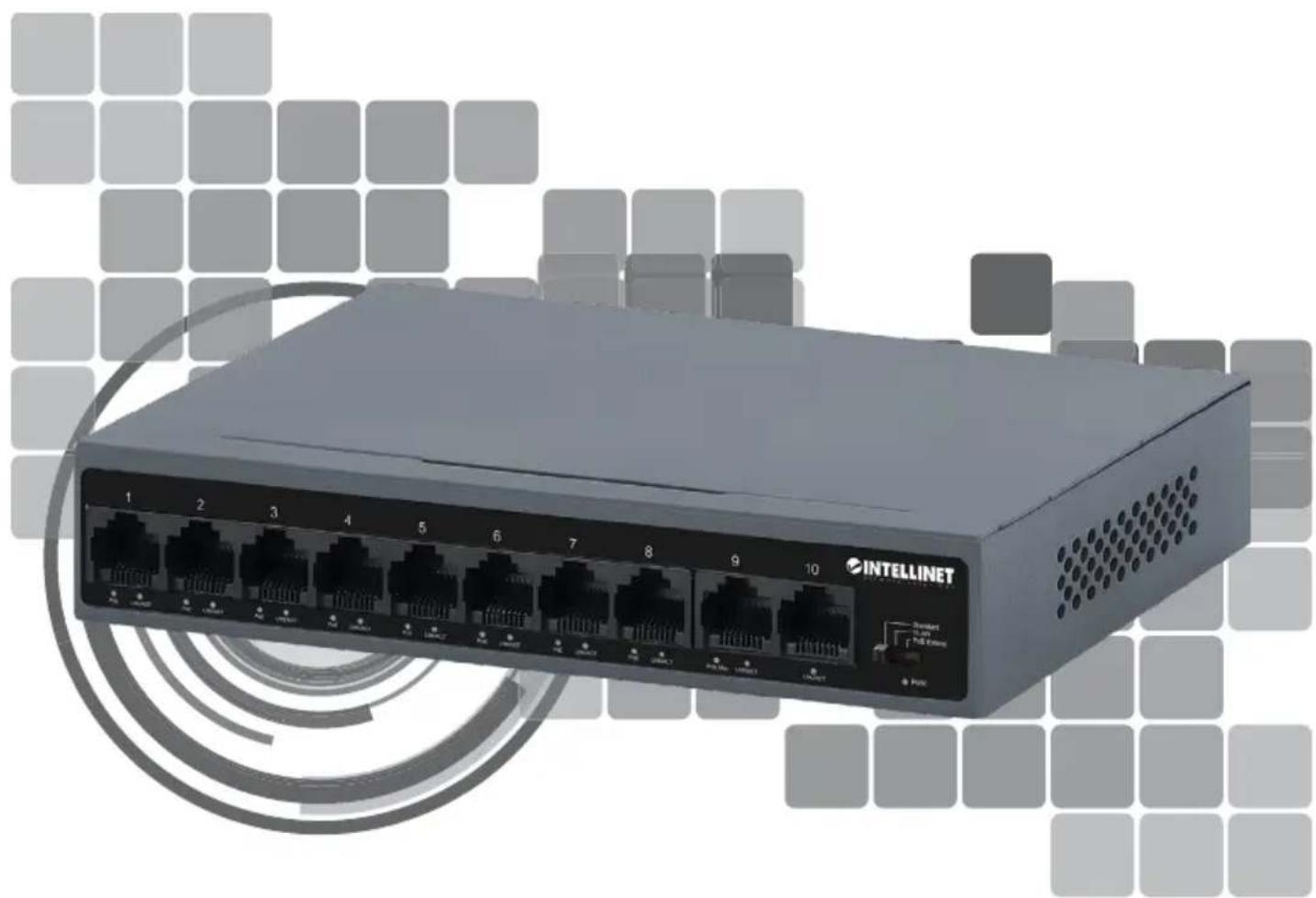
10-Port PoE+ Switch with 8 Fast Ethernet Ports and 2 FE Uplinks
Instructions
Model 562102 (IPS-08F02-95W)
Important: Read before use. • Importante: Leer antes de usar.
natural_image
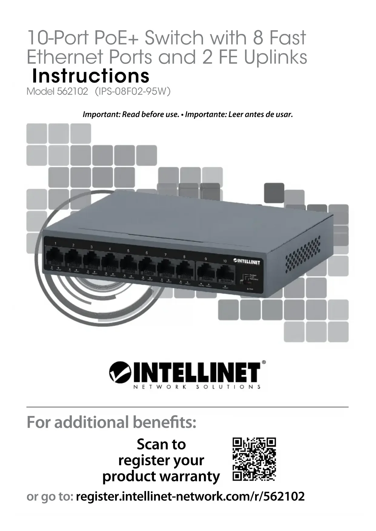
Exterior view of a Siemens network switch (INTELLINET) with ports 1–10 and a circular graphic overlay (no text or symbols on the device itself)
INTELLINET®
NETWORK SOLUTIONS
For additional benefits:
Scan to register your product warranty

text_image
QR code image containing encoded data, no visible human-readable textor go to: register.intellinet-network.com/r/562102
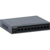
The Intellinet Network Solutions 10-Port PoE+ Switch with 8 Fast Ethernet Ports and 2 FE Uplinks passes both data and electrical power to PoE-compatible devices via standard Cat5e, Cat6 or Cat6a network cables. Equipped with eight PoE+ ports, this switch can power wireless LAN access points and bridges, VoIP phones, IP video cameras and more while delivering network speeds up to 100 Mbps. This guide presents the basic steps to set up and operate this device.
For the user manual and specifications, visit intellinet-network.com. Register your product at register.intellinet-network.com/r/562102 or scan the QR code on the cover.

Front Panel

text_image
INTELLINET 1 2 3 4 5 6 7 8 9 10 Demand PLAT PLC Guard VDD| LED Color Status Operation | |||
| PWR Green | On Power On | ||
| Off Power Off | |||
| Link/Act Green | On Valid port connection at 10/100 Mbps | ||
| Flashing Sending or receiving data | |||
| Off | No device is connected to the port. | ||
| PoE | Orange | On | The connected powered device is receiving power. |
| Flashing | Abnormal power supply | ||
| Off | No powered device (PD) is connected to the port. | ||
| PoE Max | Green | On | The system has reached a total power output of 80% |
| Off | The PoE total is nearing its maximum level | ||
All ports on the switch support Auto-MDI/MDI-X functionality, so crossover cables and uplink ports are not needed for connections to PCs, routers, other switches, etc. Cat5e/6/6a UTP/STP cables provide optimal performance; if a status LED doesn't indicate a link, check the corresponding device for proper setup and operation.
text_image
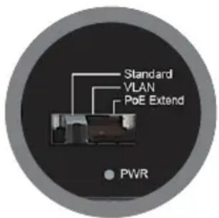
Standard VLAN PoE Extend PWRSlide Switch
Default: All ports can communicate with each other.
VLAN: Ports 1 to 8 are isolated from each other while allowing them to connect to ports 9 and 10.
PoE Extend: Extend Ethernet connection up to 250 m (820 ft.)
*NOTE: Changing the mode automatically applies the corresponding configuration without the need for a manual restart.

Rear Panel
Power
The device is compatible with DC 55V, 2A. Plug the provided power adapter into the designated DC interface on the switch.
Chassis Ground Column
Located on the side of the power supply connector, a grounding terminal connector is used to provide proper grounding for your Intellinet Network Solutions switch. If you use the chassis grounding screw, it should be wired to an object that provides earth ground. In rackmount installations, grounding is typically provided by the metal frame of the mounting rack.

Placement
Prior to use, it is recommended that the switch be placed / positioned:
- on a level surface that can support the weight of the switch
- with a minimum of 25 mm (approx. 1") of clearance on the top and sides for adequate ventilation
- away from sources of electrical noise: radios, transmitters, broadband amplifiers, etc.
• where it cannot be affected by excessive moisture
Desktop Installation
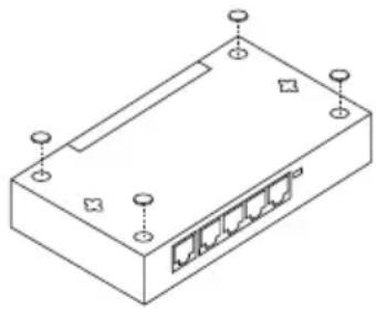
Attach the rubber feet to the corners on the bottom side of the Switch to prevent external vibrations.
Wall-mount Installation
Install two screws into the wall at the distance of the spaces on the back of the switch.
natural_image
Isometric line drawing of a rectangular electronic device with multiple ports and mounting points (no text or symbols)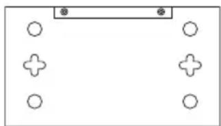
natural_image
Simple diagram with four circles arranged around a central plus sign, no text or symbols present.natural_image
Isometric line drawing of a rectangular electronic device with multiple ports and mounting points (no text or symbols)Desktop-Installation
natural_image
Simple diagram with four circles arranged around a rectangular frame, no text or symbols present.Wandmontage
natural_image
Isometric line drawing of a rectangular electronic device with multiple ports and mounting points (no text or symbols)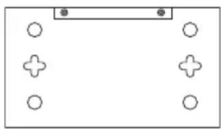
natural_image
Simple diagram with four circles and a central plus sign, no text or symbols presentnatural_image
Isometric line drawing of a rectangular electronic device with multiple ports and mounting points (no text or symbols)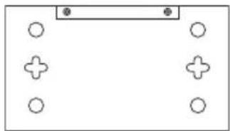
natural_image
Simple diagram with circles and plus signs arranged in a rectangular layout (no text or symbols)natural_image
Isometric line drawing of a rectangular electronic device with multiple ports and mounting points (no text or symbols)
natural_image
Simple diagram with circles and plus signs arranged around a rectangular frame (no text or symbols)natural_image
Isometric line drawing of a rectangular electronic device with multiple ports and mounting points (no text or symbols)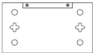
natural_image
Simple diagram with four circles and a central plus sign, no text or symbols presentWASTE ELECTRICAL & ELECTRONIC EQUIPMENT
DISPOSAL OF ELECTRIC AND ELECTRONIC EQUIPMENT
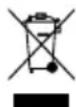
(Applicable In The European Union And Other European Countries With Separate Collection Systems)
ENGLISH: This symbol on the product or its packaging means that this product must not be treated as unsorted household waste. In accordance with EU Directive 2012/19/EU on Waste Electrical and Electronic Equipment (WEEE), this electrical product must be disposed of in accordance with the user's local regulations for electrical or electronic waste. Please dispose of this product by returning it to your local point of sale or recycling pickup point in your municipality.
This equipment has been tested and found to comply with the limits for a Class A digital device, pursuant to Part 15 of the Federal Communications Commission (FCC) Rules. These limits are designed to provide reasonable protection against harmful interference when the equipment is operated in a commercial environment. This equipment generates, uses and can radiate radio frequency energy, and if not installed and used in accordance with the instruction manual may cause harmful interference to radio communications. Operation of this equipment in a residential area is likely to cause harmful interference, in which case the user will be required to correct the interference at his own expense. Any changes or modifications made to this equipment without the approval of the manufacturer could result in the product not meeting the Class A limits, in which case the FCC could void the user's authority to operate the equipment.
CE/UKCA
ENGLISH : This device complies with the requirements of CE 2014/30/EU (UKCA Electromagnetic Compatibility Regulations 2016) and / or 2014/35/EU (UKCA Electrical Equipment [Safety] Regulations 2016). The Declaration of Conformity for is available at:
support.intellinet-network.com/barcode/562102





North America
IC Intracom America
550 Commerce Blvd.
Oldsmar, FL 34677 USA
Asia & Africa
IC Intracom Asia
4-F, No. 77, Sec. 1, Xintai 5th Rd.
Xizhi Dist., New Taipei City 221, Taiwan
Europe
IC Intracom Europe
Löhbacher Str. 7, D-58553
Halver, Germany
All trademarks and trade names are the property of their respective owners.
All trademarks and trade names are the property of their respective owners. © IC Intracom. All rights reserved. Intellinet Network Solutions is a trademark of IC Intracom, registered in the U.S. and other countries.