
508278 - Switch Intellinet - Free user manual and instructions
Find the device manual for free 508278 Intellinet in PDF.


| Product Type | 8-Port Gigabit Ethernet PoE+ Web-Managed Industrial Switch with 2 SFP Ports |
| Dimensions (L x W x H) | 280 x 180 x 44 mm (11.02 x 7.09 x 1.73 in) |
| Weight | 1.6 kg (3.5 lbs) |
| Power Supply | Dual external redundant DC 48-57 V input via terminal block; PoE budget up to 240 W (requires external power supply) |
| PoE Output | Up to 30 W per port, IEEE 802.3af/at compliant |
| Ports | 8 x 10/100/1000 Mbps RJ45 PoE+ ports, 2 x Gigabit SFP slots |
| Switching Capacity | 20 Gbps |
| Management Features | Web GUI, Telnet, SSH, Console; VLAN, QoS, STP/RSTP/MSTP, IGMP Snooping, Port Mirroring, Link Aggregation, ACL, DHCP Snooping, IP Source Guard, SNMP, RMON |
| Environmental Protection | IP30 metal housing; operating temperature -40 to 85°C (-40 to 185°F); shock, freefall, vibration resistant |
| Mounting | DIN-rail or desktop |
| Surge Protection | Port surge protection up to 6 kV; grounding terminal |
| LED Indicators | Power, Link/ACT per RJ45 port, PoE status, SFP link/activity |
| Safety & Compliance | CE, FCC Class B; WEEE disposal directive |
| Maintenance | Keep clean with dry cloth; ensure adequate ventilation; no user-serviceable parts |
| Spare Parts & Repairability | No user-replaceable parts; contact place of purchase for warranty service |
| General Information | Brand: Intellinet; Model: 508278; Manual available at intellinetnetwork.com/barcode/508278 |
Frequently Asked Questions - 508278 Intellinet
User questions about 508278 Intellinet
0 question about this device. Answer the ones you know or ask your own.
Ask a new question about this device
Download the instructions for your Switch in PDF format for free! Find your manual 508278 - Intellinet and take your electronic device back in hand. On this page are published all the documents necessary for the use of your device. 508278 by Intellinet.
USER MANUAL 508278 Intellinet
8-Port Gigabit Ethernet PoE+ Web-Managed Industrial Switch with 2 SFP Ports
User Manual
Model 508278 (IIS-8G02MPOE)


INTELLINET®
NETWORK SOLUTIONS
intellinetnetwork.com
Important: Read before use. • Importante: Leer antes de usar.
1 TABLE OF CONTENTS
2 Product Introduction....4
2.1 Product Overview....4
2.2 Features....4
2.3 Specifications ....5
2.4 External Component Description....6
2.4.1 Front Panel....6
2.4.2 Left Panel 7
2.4.3 Rear Panel 8
2.5 Package Contents....8
3 Installing and Connecting the Switch 8
3.1 Installation....8
3.1.1 DIN-rail Installation 9
3.1.2 Desktop Installation 9
3.2 Terminal Block Installation / Power on the Switch....9
4 Connection to the Switch 10
4.1 Connecting Computer.... 10
4.2 How to Log in to the Switch 10
5 Saving the Configuration....12
6 Switch Configuration....13
6.1 Home....13
6.1.1 Port Information 13
6.1.2 Port Information, Equipment Configuration and Port Statistics 13
6.2 Quick Setup 15
6.3 Port Settings....16
6.3.1 Basic Config....16
6.3.2 Port Aggregation....17
6.3.3 Port Mirroring....19
6.3.4 Port speed limit....20
6.3.5 Broadcast storm....21
6.3.6 Port isolation....22
6.4 VLAN 25
6.4.1 Trunk Port Settings....27
6.4.2 Hybrid Port Settings 28
6.4.3 Setup Example *** 29
6.5 Fault/Safety 31
6.5.1 Anti Attack....31
6.5.2 Channel Detection 38
6.5.3 ACL Access Control List 40
6.6 PoE 43
6.6.1 PoE Config....43
6.6.2 PoE Port Config 44
6.6.3 PoE Delay Config 46
6.7 Spanning Tree Protocol (STP) 47
6.7.1 MSTP Region 50
6.7.2 MSTP Bridge 51
6.8 DHCP Relay Agent 53
6.8.1 DHCP Relay....53
6.8.2 Option82 53
6.9 DHCP Server 55
6.9.1 DHCP Config 55
6.10 IGMP Snooping....57
6.10.1 IGMP Config 58
6.10.2 IGMP Filter Policy Config....60
6.11 Terminal Access Controller Access-Control System (TACACS+) 61
6.12 Radius....63
6.12.1 Radius General Config....63
6.12.2 Radius Server Config 64
6.13 AAA....65
6.13.1 Enable Config....65
6.13.2 Region Config....65
6.14 QoS – Quality of Service 66
6.14.1 QoS Rules 66
6.14.2 Queue Config 67
6.14.3 Queue Mapping....68
6.15 Address Table.... 69
6.15.1 Address Table Config....69
6.16 SNMP....70
6.16.1 SNMP Config 71
6.16.2 RMON Config 75
6.17 System....78
6.17.1 System Config 78
6.17.2 System Update....82
6.17.3 Configuration Management....83
6.17.4 Config Save 84
6.17.5 Administrator Settings 84
6.17.6 Information Collect 85
7 WASTE ELECTRICAL & ELECTRONIC EQUIPMENT 86
8 WARRANTY....86
9 REGULATORY STATEMENTS....87
2 PRODUCT INTRODUCTION
Thank you for purchasing the Intellinet Network Solutions 8-Port Web-Managed Gigabit Ethernet Switch. Before you install and use this product, read this manual carefully to understand its functions.
2.1 PRODUCT OVERVIEW
The Intellinet 8-Port Gigabit Ethernet PoE+ Web-Managed Industrial Switch with 2 SFP Ports provides eight 10/100/1000 Mbps Ethernet ports that are compatible with the IEEE802.3af/at standards and two Gigabit SFP optical ports. Each PoE port can provide power up to 30 W. The switch's store and forward technology, combined with dynamic memory allocation, ensures that the bandwidth is allocated efficiently to each port. The switch supports a variety of management functions, including STP/RSTP, Trunking, LACP, IGMP, VLAN, QoS, RMON, PoE power management, PoE device automatic detection, PoE power supply scheduling, bandwidth management and port mirroring. This product is designed for harsh industrial environments and offers dual, external, redundant, wide-range DC 48 – 57 V power inputs, IP30 protection with a metal chassis design, support-rail installation, port surge protection up to 6 KV, and a working temperature range of -40 – 85°C (-40 – 185°F) to meet the needs of industrial automation locations.
2.2 FEATURES
- Provides power and data connections for up to eight PoE network devices
- Domotz compatible for cloud management (may require firmware upgrade)
• IP30-rated metal housing to withstand harsh industrial conditions - Wide operating temperature: -40 – 85°C (-40 – 185°F)
- Option for DIN-rail installation
• 10/100/1000 auto-sensing ports that automatically detect optimal network speeds - Two small form-factor pluggable GBIC module slots (SFP)
- IEEE 802.3at/af compliant RJ45 PoE/PoE+ output ports
• Power output up to 30 watts per port - PoE power budget of 240 watts (depending on the power supply used)
- Two redundant DC inputs (45 – 57 V) with I/O terminal block
• Power failure alarm (one-way relay output, current load capacity 1A @ 24 V DC)
• Port surge protection up to 6 kV - Grounding point to protect equipment from external electrical surges
- Rated for shock (IEC 60068-2-27), freefall (IEC 60068-2-32) and vibration (IEC 60068-2-6)
• 20 Gbps switch fabric - Powered Device Monitor feature (PDM) to restart any connected PoE device that fails to respond or send out network traffic
• Supports IEEE 802.3at/af detection and short circuit, overload and high-voltage protection - PoE scheduling to help save energy
• Auto-MDIX and NWay auto-negotiation support on all RJ45 ports - Supports SNMP Management and Remote Monitoring (RMON), VLAN (tag-based and port-based), two types of QoS: port-based and DSCP, link aggregation (trunking), bandwidth control per port, port mirroring, Rapid Spanning Tree/Spanning Tree Protocol
-
Provides IEEE 802.1x port-based security
• IGMP Snooping for multicast filtering -
Broadcast storm control with multicast packet rate settings
• Supports 8k MAC address entries with Auto-learning and Auto-aging and jumbo frames up to 9 kBytes
• Full/half duplex operation; IEEE 802.3x flow control for full duplex - Configuration via Web browser, Telnet, SSH or console port
- Requires additional industrial power supply (not included)
2.3 SPECIFICATIONS
Standards
- IEEE 802.1d (Spanning Tree Protocol)
• IEEE 802.1p (Traffic Prioritization) - IEEE 802.1q (VLAN Tagging)
- IEEE 802.1s (Multiple Spanning Tree Protocol)
- IEEE 802.1w (Rapid Spanning Tree Protocol)
• IEEE 802.3ad (Link Aggregation)
• IEEE 802.3 (10Base-T Ethernet) - IEEE 802.3ab (Twisted Pair Gigabit Ethernet)
- IEEE 802.3ad (Link Aggregation Control Protocol LACP)
- IEEE 802.3af (Power over Ethernet 802.3at Type 1)
- IEEE 802.3at (Power over Ethernet 802.3at Type 2)
- IEEE 802.3az (Energy Efficient Ethernet EEE)
- IEEE 802.3u (100Base-TX Fast Ethernet)
- IEEE 802.3x (flow control, for full duplex mode)
Power
- Input: 100 – 240 VAC, 50 – 60 Hz
Environmental
- Metal housing
- Dimensions: 280 (L) x 180 (W) x 44 (H) [mm] / 11.02 (L) x 7.09 (W) x 1.73 (H) [in.]
• Weight: 1.6 kg (3.5 lbs.) - Operating temperature: 0 - 45^ C (32 - 113°F)
- Operating humidity: 10 – 90% RH, non-condensing
- Storage temperature: -10 – 70°C (14 – 158°F)
Package Contents
• 8-Port Gigabit Ethernet PoE+ Web-Managed Industrial Switch with 2 SFP Ports
- 19" rackmount brackets
- Power cable
- Instructions
2.4 EXTERNAL COMPONENT DESCRIPTION
2.4.1 Front Panel
The front panel of the switch consists of eight 10/100/1000 Mbps RJ-45 ports, two SFP ports, one console port, one Reset button and a series of LED indicators as shown below.

10/100/1000 Mbps RJ-45 ports (1 - 8):
Connect to a device with a bandwidth of 10 Mbps, 100 Mbps or 1000 Mbps; each has a corresponding 10/100/1000 Mbps LED.
SFP ports (SFP1, SFP2):
Install SFP modules and connect to the device with a bandwidth of 1000 Mbps; all ports have a corresponding 1000 Mbps LED.
Console port (Console):
Connects with the serial port of a computer or terminal to monitor and configure the switch.
Reset button (Reset):
Restores the system to factory default settings; hold the reset button for five seconds while the device powers itself on.
LED indicators:
Enable the administrator to monitor, diagnose and troubleshoot any potential problem with the switch, its connection or attached devices.

The following chart provides an explanation of each LED indicator on the switch.
| LED | Color | Status | Status Description |
| Link/ACT | Green | On | A device is connected to the port |
| Off | No link | ||
| Flashing | Sending or receiving data | ||
| PoE | Orange | On | A Powered Device (PD) is connected to the port and receiving power |
| Off | No PD is connected to the corresponding port, or there is a problem | ||
| SFP1 | Green | On | A device is connected to the port |
| SFP2 | Off | No connection | |
| Flashing | Sending or receiving data | ||
| PWR | Green | On | System Powering on normally |
| Off | System Powering off or working abnormally | ||
| PWR1 | Green | Off | Power off |
| PWR2 | On | Power on |
2.4.2 Left Panel
The left panel of the Switch contains the six-pin terminal block and a Grounding Terminal , as shown.

natural_image
Exterior view of a black INTELLINET network switch device with ports and a green connector (no visible text or symbols on the device body)Terminal block
External, redundant, wide-range DC 48 - 57 V power input.
Grounding terminal
Located on the right side of the terminal block; wire to a grounded object for lightning protection and voltage protection.
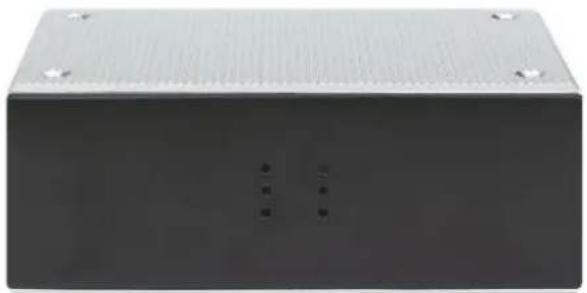
2.4.3 Rear Panel
The rear panel of the Switch contains one DIN-rail seat, as shown.
natural_image
Exterior view of a rectangular electronic device with ventilation grilles and mounting holes (no visible text or symbols)Guide rail seat
Supports DIN-rail installation
2.5 PACKAGE CONTENTS
Before installing the Switch, make sure that the items in the packing list are present. If any part is missing or damaged, please contact your place of purchase.
• One 8-Port Gigabit Ethernet PoE+ Web-Managed Industrial Switch with 2 SFP Ports
• One DIN-rail mount bracket
3 INSTALLING AND CONNECTING THE SWITCH
This section describes how to install your PoE Ethernet Switch and make connections to it. Please read the following topics and perform the procedures in the order presented.
3.1 INSTALLATION
Follow the instructions below to avoid incorrect installation, which can damage the device or threaten your safety.
• Fix the DIN-rail seat of Switch onto a fixed rail.
- Make sure the Switch works in the proper DC-input range and matches the voltage range of Switch.
- To prevent electrocution, DO NOT OPEN THE SWITCH HOUSING, even when power is disconnected.
- Make sure that there is proper heat dissipation from and adequate ventilation around the Switch.
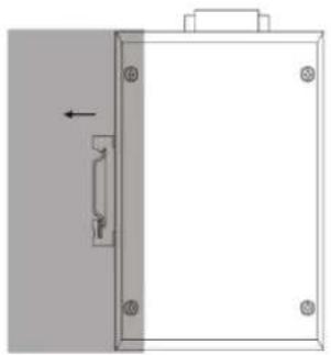
3.1.1 DIN-rail Installation
Installation steps:
a. Fix the bottom of the Switch's DIN rail onto a fixed rail.

natural_image
Technical line drawing of a mechanical component with mounting holes and a vertical guide (no text or symbols)b. And then push the DIN rail seat to the fixed rail slowly.
natural_image
Simple line drawing of a door frame with a handle and mounting holes, no text or symbols present3.1.2 Desktop Installation
Allow adequate space for ventilation between the device and the objects around it.
3.2 TERMINAL BLOCK INSTALLATION / POWER ON THE SWITCH
The Switch is powered on by the dual external, redundant, wide-range DC 48 – 57 V power-input terminal blocks.
NOTE: Ensure all power is off/disconnected before beginning!
- Loosen appropriate screws.
- Insert bare power-supply wires into appropriate terminal slots (positive wire into positive slot; negative wire into negative slot).
- Tighten appropriate screws to secure wires. (If desired, repeat steps 1 - 3 on second input pair.)
- Install block into the device and tighten screws. Check that the power indicator is ON. An ON LED indicates the power connection is OK.

4 CONNECTION TO THE SWITCH
4.1 CONNECTING COMPUTER
Use standard Cat5/5e Ethernet cables (UTP/STP) to connect the switch to end nodes as described below. Switch ports will automatically adjust to the characteristics (MDI/MDI-X, speed, duplex) of the device to which they are connected.

natural_image
Line drawing of a laptop connected to a network switch (no text or symbols)Figure 7 - PC Connect
The LNK/ACT/Speed LEDs for each port are illuminated when the link is available.
4.2 How to Log IN TO THE SWITCH
As the switch provides Web-based management login, configure your computer's IP address manually to log on to the switch. The default settings of the switch are shown below.
| Parameter | Default Value |
| Default IP address | 192.168.2.1 |
| Default Username | admin |
| Default Password | Serial number on switch bottom |
Log on to the configuration window of the switch through following steps:
- Connect the switch with the computer NIC interface.
- Power on the switch.
- Check whether the IP address of the computer is within this network segment: 192.168.2.xxx ("xxx" range is 2-254); for example, 192.168.2.100.
- Open the browser and go to the URL http://192.168.2.1. The switch login window appears, as shown below.

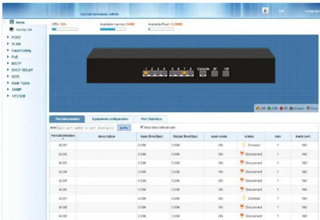
Enter the Username and Password (the factory default Username is admin and the Password is the serial number on switch bottom), and then click "LOGIN" to log in to the switch configuration window as below.
The Intellinet Network Solutions 8-Port Gigabit Ethernet PoE+ Web-Managed Switch provides a myriad of configuration options, many of which are designed for experienced network administrators and aren't easy to configure. It would be a real shame if all the configuration data was lost after a power failure or after the switch was restarted. In order to make the configuration permanent, it needs to be saved.
Here is how:

Are you sure to save the configuration?
If you do not perform this function, you risk losing all the settings after the switch restarts.
6 SWITCH CONFIGURATION
This chapter describes how to use the web-based management interface (Web UI) for this switch.
6.1 HOME

6.1.1 Port Information

A green square indicates the port link is up at Gigabit speeds. An amber square indicates a link speed of 100 Mbps. A gray square indicates the port link is down, and a PoE connection is indicated by the color red.
6.1.2 Port Information, Equipment Configuration and Port Statistics
This section provides real-time information about the ports, basic settings and traffic statistics.
| Port information | Equipment configuration | Port Statistics | |||||
| key Input port number or port description query Real time refresh rate | |||||||
| Port information | description | Input flow(Bps) | Output flow(Bps) | open state | status | vlan | trunk port |
| GI 0/1 | 6.41M | 6.77M | ON | Connect | 1 | NO | |
| GI 0/2 | PoE_Camera | 19.54K | 63.17K | ON | Connect | 1 | NO |
| GI 0/3 | 0.00K | 0.00K | ON | Disconnect | 1 | NO | |
| GI 0/4 | 0.00K | 0.00K | ON | Disconnect | 1 | NO | |
| Item | Description |
| Port Information | Displays the port number. The nomenclature is as follows: = Gigabit Ethernet 0/ = Switch 0 (which means this device) 1-10 = Port number. Ports 9 and 10 are SFP module slots. |
| Description | Optional description for the port, as entered in the basic port configuration. |
| Input Flow (bps) | Inbound traffic rate, measured in "bits per second." |
| Output Flow (bps) | Outbound traffic rate, measured in "bits per second." |
| Open State | ON = Port is activated in the basic port configuration and will accept connections from networking devices.OFF = Port is deactivated in basic port configuration. |
| Status | Connect: A networking device is connected to the port and has an active link.Disconnect: No device is connected to the port. |
| VLAN | If the port belongs to a VLAN, its ID is displayed here. ID 1 = default. |
| Trunk Port | Yes = The port is part of an LACP trunking group.No = The port is not part of an LACP trunking group. |
| Port information | Equipment configuration | Port Statistics |
| Total number of devicesVLAN | 1 | More settings |
| Number of port aggregation | 0 | More settings |
| Port mirror | OFF | More settings |
| protectbind | OFF | More settings |
| DHCP attack for anti | OFF | More settings |
| DOS attack for anti | OFF | More settings |
This tab displays information about various functions and provides a short-cut that allows direct configuration of that part of the switch settings.
| Port information | Equipment configuration | Port Statistics | ||||
| clear count | ||||||
| Port information ▲ | Number of bytes received | Number of bytes sent | Incomplete data packet number | Over large data packets | CRC error packet | Conflict times |
| GI0/1 | 6393027 | 6778647 | 0 | 0 | 0 | 0 |
| GI0/2 | 18304 | 63911 | 0 | 0 | 0 | 0 |
| GI0/3 | 0 | 0 | 0 | 0 | 0 | 0 |
| GI0/4 | 0 | 0 | 0 | 0 | 0 | 0 |
This tab displays real-time information about the data packets for each port.
6.2 QUICK SETUP

Quickly Set
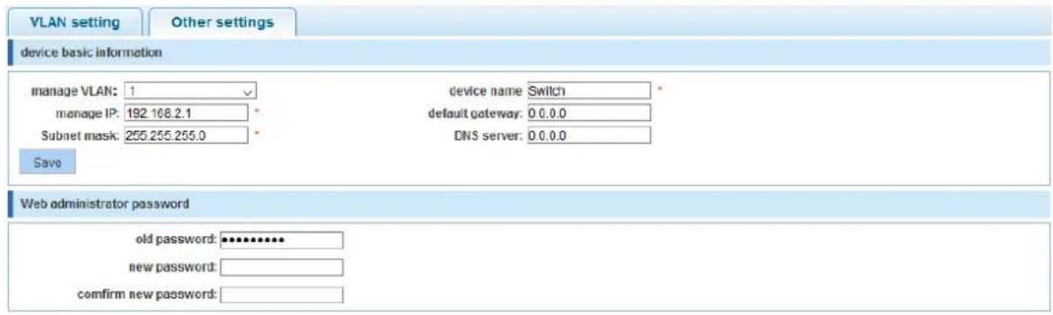
The Intellinet Network Solutions 8-Port Gigabit Ethernet PoE+ Web-Managed Switch provides a setting that offers direct access to some of the core functions of the device, namely VLAN, trunking, device IP address and admin password. Even though the function is called "Quickly Set," there is no need to rush. Take as much time as you like with the configuration.
![VLAN setting Other settings VLAN setting VLAN ID VLAN name VLAN IP address port operation 1 VLAN0001 192.168.2 1/24 1-8 new VLAN delete selected VLAN first page prev page [1] next page last page 1 / 1page first page prev page [1] next page last page 1 / 1page Trunk settings port name port description Native Vlan Allowing Vlan operation new Trunk port delete selected Trunk port first page prev page [1] next page last page 1 / 1page](/content/2026/05/905137/images/4e06bb96d3c77faa1f5a2cebe072978926b39062aa4c02f2e6924341eeb89c69.jpg)

next step

Refer to subsequent sections in this user guide for additional information about the individual functions.
6.3 PORT SETTINGS
6.3.1 Basic Config
PORT
- Basic Config
Access the parameters related to each of the 10 ports. The screen is divided into two sections. The upper section displays an image of the 10 ports of the Intellinet Network Solutions switch. In order to make changes to a port, simply click to select it.


Create a selection of multiple ports at once:


Once one port or multiple ports are selected, make changes to the port settings.


| Item | Description |
| Port description | Optional description for the port. A maximum of 80 characters can be provided. No special characters or spaces are allowed. |
| Port Speed | 10M: Force a connection to be made at 10 Mbps.100M: Force a connection to be made at 100 Mbps.1000M: Force a connection to be made at 1000 Mbps.Auto: The switch and connected device negotiate the best possible connection speed. |
| Flow Control | IEEE 802.3x flow control is the process of managing the rate of data transmission between two nodes (i.e., the switch and a connected network client) to prevent a fast sender from overwhelming a slow receiver. It provides a mechanism for the receiver to control the transmission speed so that the receiving node is not overwhelmed with data from the transmitting node. That sounds like it's a good thing, and it is. So why is the option by default set to "disabled"? The short answer is because you normally don't need it and because it can, in very rare instances, have a negative impact on the overall performance in your network. The TCP protocol already provides its own flow control mechanism, allowing a sender to throttle back the speed if the receiver is having problems keeping up. |
| Status | ON: Activate the port.OFF: Disables the port. No connections to it can be made. |
| Duplex Mode | This parameter controls the duplex mode. In a full-duplex system, both parties can communicate to the other simultaneously. An example of a full-duplex device is a telephone; the parties at both ends of a call can speak and be heard by the other party simultaneously. In networking terms, full duplex allows users to receive and transmit data at the same time, whereas half duplex does not. If the telephone is an example for full duplex, then a push-to-talk CB radio or "walkie-talkie" represents half duplex. The switch can either receive or send data, but it can never happen simultaneously. Unless you have a specific reason not to do so, this should be left in "Auto" mode. |
| Cable Type Detection | Auto MDI-X automatically detects the required cable-connection type and configures the connection appropriately, removing the need for crossover cables to interconnect switches or for connecting PCs peer-to-peer. As long as it is enabled on either end of a link, either type of cable can be used. For auto MDI-X to operate correctly, the data rate on the interface and duplex setting must be set to "auto." When two auto MDI-X ports are connected together, which is normal for modern products, the algorithm resolution time is typically < 500 ms. However, a ~1.4 second asynchronous timer is used to resolve the extremely rare case (with a probability of less than 1 in 5 × 10^21 ) of a loop where each end keeps switching. If you don’t understand any of this, simply leave this value on "Auto." |
The screen also shows a table that lists all 10 ports along with their parameters. The "mega frame" value refers to jumbo frames, which are Ethernet frames with more than 1500 bytes of payload. Define the size of the jumbo frames in the section SYSTEM -> SYSTEM CONFIG.
| Port list | ||||||||
| Port | Port description | Port status | Port speed | Working mode | mega frame | Cross line order | Flow control | Operation |
| G10/1 | On | 1000M | Duplex | 1518 | Auto | On |  | |
| G10/2 | On | 100M | Duplex | 1518 | Auto | Off | ||
| G10/3 | On | Auto | Duplex | 1518 | Auto | Off | ||
| G10/4 | On | Auto | Duplex | 1518 | Auto | Off | ||
Clicking the pencil allows the administrator to edit the port settings, exactly the same way as
directly selecting the port(s) as shown on the previous page.
6.3.2 Port Aggregation
PORT
- Basic Config
- Port Aggregation
Port aggregation is a method of using multiple Ethernet ports in parallel to increase throughput beyond what a single connection could sustain and to provide redundancy in case one of the links should fail. As this is essentially a grouping of ports into one logical unit, we call them Link Aggregation Groups, or "LAG" for short.
Standard Setup

Gigabit Switch 2
LAG / Trunking Setup

Gigabit Switch 2
This page is used to set up LAGs. Create up to eight different LAGs; each can have up to eight member ports. Each LAG can be given a custom name, and you must select the ports for the LAG. The example below shows a LAG group set up with four member ports.
Port Aggregation
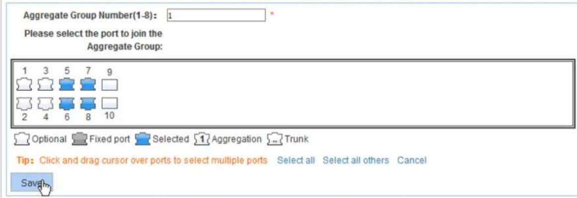
| Item | Description |
| Aggregate port number | This is the link aggregation group (LAG) number |
| Please select the port to join the aggregate port | Select the member ports that belong to this LAG |
| Port Aggregation List | ||
| Aggregation Group Number | Group Members | Edit / Delete |
| 1 | 5.6.7.8 | |
6.3.3 Port Mirroring
PORT
- Basic Config
- Port Aggregation
- Port Mirroring
Port mirroring is the ability of a network switch to send a copy of network packets seen on a switch port or ports to a network-monitoring device connected to another switch port (i.e., a computer equipped with a packet sniffer utility). The Intellinet Network Solutions 8-Port Gigabit Ethernet PoE+ Web-Managed Switch provides up to four groups for port-mirroring settings.

flowchart
graph TD
    A["PC Clients"] --> B["Server"]
    B --> C["Source Port"]
    B --> D["Destination port"]
    C --> E["Laptop"]
    D --> F["E-Mail Server"]
The example below shows the setup of one mirror group where all traffic occurring on port 1 is mirrored to port 6.
Port Mirroring
Mirror Group Number (1-4):

Please choose the source port:(Selecting multiple source ports can affect the device performance


Optional

Fixed port

Selected

Aggregation

Trunk
Tip:
Click a
nd drag
ursor over
ports to
select
multiple ports
Select all
Select all others
Cancel
Please choose the destination port:(Can only choose one port)


Optional

Fixed port

Selected

Aggregation

Trunk
Save
6.3.4 Port speed limit
PORT
- Basic Config
- Port Aggregation
- Port Mirroring
- Port Limit
This feature allows the user to limit the data rates for a particular port on the Intellinet Network Solutions 8-Port Gigabit Ethernet PoE+ Web-Managed Switch. When the data rate exceeds user-configured values, the Intellinet Network Solutions switch drops packets immediately. Rate limiting is configured for two types of transmissions, which are ingress and egress. Ingress traffic is received on any given port (incoming, inbound, download or input speed), whereas egress traffic is sent out (outgoing, outbound, upload or output speed) to another network client.
The Intellinet Network Solutions switch allows the user to control the available bandwidth for each port individually. The speed is measured in kbps, which stands for kilobits per second. The default is 1 million, which is the equivalent of 1 Gigabit per second. Values entered must be multiples of "16" (e.g., 16, 32, 48, ..., 512, ..., 1024, etc.).

| Item | Description |
| Port number 1 - 10 | Select individual ports or a range of ports. |
| Input speed limit (multiple of 16) | Provide the ingress rate in kbps. |
| Output speed limit (multiple of 16) | Provide the egress rate in kbps. |
6.3.5 Broadcast storm
PORT
- Basic Config
- Port Aggregation
- Port Mirroring
- Port Limit
- Storm Control
Storm control prevents a broadcast storm from disrupting LAN interfaces. A broadcast storm occurs when broadcast packets flood the subnet, creating excessive traffic and degrading network performance. Errors in the protocol-stack implementation or in the network configuration can cause a broadcast storm. The Intellinet Network Solutions switch allows the user to configure the maximum allowed packets-per-second (pps) rates for three different types of packets. It's possible to set all 10 ports to the same value or provide individual values.
Storm Control

| Item | Description |
| Port number 1 – 10 | Select individual ports or a range of ports. |
| Broadcast limit | Enter the maximum pps for broadcast packets. |
| Multicast limit | Enter the maximum pps for multicast packets. |
| Unicast limit | Enter the maximum pps for unicast packets. |
| Multicast Type | Define whether to apply the storm filter only to multicast packets with unknown destination MAC addresses or to both known and unknown destinations. |
| Unicast Type | Define whether to apply the storm filter only to unicast packets with unknown destination MAC addresses or to both known and unknown destinations. |
6.3.6 Port isolation

The port isolation function allows an administrator to configure the Intellinet Network Solutions switch in a way that prevents PCs on different ports from communicating with each other but without configuring a VLAN.

| Item | Description |
| Source Port | Select the port you wish to isolate. |
| Isolation Port | Select the port(s) to which packets from the source port can be forwarded. More than one port can be selected here. |
6.3.6.1 Configuration Example \*\*\*:
- Three PCs, one NAS, and one router are connected to the Intellinet Network Solutions switch.
- PC1 is connected to Port 1.
- PC2 is connected to Port 2.
- PC3 is connected to Port 3.
- The NAS is connected to Port 4.
- The router is connected to Port 5.
- PC1 can access the NAS and the router.
- PC2 and PC3 can only access the router.

flowchart
graph TD
    WAN["WiN"] -->|Port 4| NAS["NAS"]
    NAS -->|Port 5| Router["Router"]
    Router -->|Port 2| PC1["PC 1"]
    Router -->|Port 3| PC2["PC 2"]
    Router -->|Port 1| PC1
    style WAN fill:#99ccff,stroke:#333
    style PC1 fill:#e6f7ff,stroke:#333
    style PC2 fill:#e6f7ff,stroke:#333
    style PC3 fill:#e6f7ff,stroke:#333
    style Port 4 fill:#ffffff,stroke:#000
    style Port 5 fill:#ffffff,stroke:#000
    style Port 1 fill:#ffffff,stroke:#000
    style Port 2 fill:#ffffff,stroke:#000
    style Port 3 fill:#ffffff,stroke:#000
PC1 on port 1:
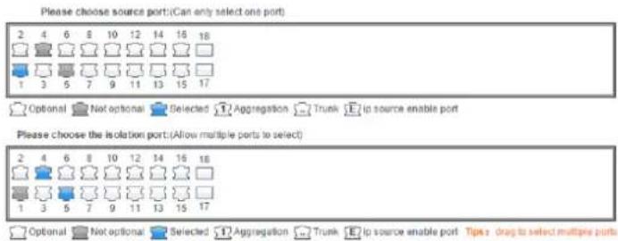
PC2 on port 2:

PC3 on port 3:

NAS on Port 4:

Router on Port 5:

When completed, the configuration will look like this. To better understand what is happening, it helps to consider the isolated ports as the ports with which the source ports can communicate.
| Source port | isolate port | Operation |
| 1 | 4 5 | |
| 2 | 5 | |
| 3 | 5 | |
| 4 | 1 | |
| 5 | 1 2 3 |
*** Screenshots taken from 16-Port Gigabit Ethernet PoE+ Web-Managed Switch with 2 SFP Ports, model 561341. The setup of the 8-port version is identical.
6.4 VLAN
VLAN
Vlan Config
A virtual LAN (VLAN) is any broadcast domain that is partitioned and isolated in a computer network at the datalink layer (OSI layer 2). VLANs are datalink layer (OSI layer 2) constructs that are analogous to IP subnets, which are network-layer (OSI layer 3) constructs. VLANs can be used to partition a local network into several distinctive segments.
VLAN technology provides the following advantages:
-
Broadcast traffic does not cross into different VLANs, which reduces bandwidth utilization and improves network performance.
-
Security in your LAN can be improved, since packets in different VLANs cannot communicate with each other directly.
-
With VLAN, clients can be allocated to different working groups, and users from the same group do not have to be within the same physical area, which makes network maintenance much easier and more flexible.
VLAN technology knows three types of ports—access, trunk and hybrid ports.
- Access Ports (untagged)
a. Access ports are designed to tag any incoming packet with the VLAN ID the port has been assigned to.
b. The switch drops tagged VLAN packets that arrive at the access port.
c. As far as the Intellinet Network Solutions switch is concerned, any port that isn't defined as a trunk or hybrid port is considered an access port.
- Trunk Ports (tagged)
a. Trunk ports are designed to filter out packets that have either no VLAN tag or VLAN tags that are not on the allowed VLAN ID list.
b. Trunk ports do not remove any existing VLAN tags from incoming packets.
c. Trunk ports do not add a VLAN tag to any incoming untagged packet.
d. Trunk ports are ideal for switch-to-switch connections or for devices that have the ability to tag packets by themselves such as VoIP phones.
- Hybrid Ports
a. These are a combination of access and trunk ports.
b. Hybrid ports will tag any incoming packet that has no VLAN ID with the VLAN ID the port has been assigned to.
c. Hybrid ports will also act as trunk ports for packets that have a VLAN tag.
![VLAN setting Trunk-port setting Hybrid-port setting VLAN list □ VLAN ID VLAN name VLAN IP address port operation 1 VLAN0001 192.168.2.1/24 1-18 New VLAN delete selected VLAN first page prev page [1] next page last page1 / 1page](/content/2026/05/905137/images/52a6a242a62077f51737f3d64f3330d803fdd7b0153253252f8e6d21c298c2b6.jpg)
New VLAN:
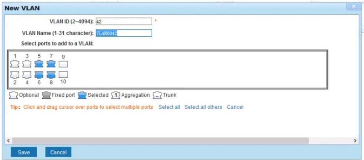
| Item | Description |
| VLAN ID | Type in the ID for the new VLAN. This value cannot be "1" nor any ID already setup on the switch. |
| VLAN Name | Provide a descriptive name for the VLAN (e.g., "VOICE"). |
| Choose to join the VLAN port | Select all the ports you wish to be a part of this VLAN. Note that these ports will act as access ports. They will add the VLAN ID to any untagged packet and reject any incoming packets that have a VLAN tag. |
Note: VLAN ID 1 is the default VLAN, which cannot be removed. However, access ports that are assigned to another VLAN will be automatically removed from VLAN 1. The screen shot below shows what the setup looks like after the above VLAN has been added:
![VLAN Settings Trunk Port Settings Hybrid Port Settings VLANs □ VLAN ID VLAN Name VLAN IP Port Edit / Delete 1 VLAN0001 192 168.2.1/24 1-4 9-10 □ 42 VLAN0042 5-8 New VLAN Delete VLAN First page prev page [1] next page last page: / 1 page](/content/2026/05/905137/images/72592a2de387be44c6fa786146993583a2b3e11906c40de66a6491aed3bd6e54.jpg)
6.4.1 Trunk Port Settings
A trunk port transmits tagged packets and is used to connect different switches with one another.
![VLAN setting Trunk-port setting Hybrid-port setting Trunk port list port port description Native Vlan Allowing VLAN operation New Trunk-Port delete selected Trunk-port first page prev page [1] next page last page 1 / 1page](/content/2026/05/905137/images/6c2f6fe3d3252f34dd629974dd8c1f258c7e0ce7a54aa60683a56fde88049dde.jpg)
New Trunk-Port:
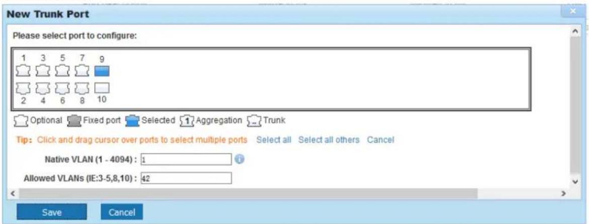
| Item | Description |
| Native VLAN ID | The native VLAN ID is the untagged VLAN on an IEEE 802.1q trunked port.The native VLAN and management VLAN (see SYSTEM->SYSTEM CONFIG) can be the same, but in terms of security, it is better that they aren't. If a switch receives an untagged frame on a trunk port, it is assumed to be part of the Native VLAN that is designated on the switch trunk port. |
| Allowing VLAN | Enter the IDs of all VLANs that you wish the trunk port to forward. All other tagged packets will be dropped.Note that any value you enter here must first be defined as a VLAN in the previous VLAN settings page. |
6.4.2 Hybrid Port Settings
A Hybrid port is a combination of a trunk and an access port.
![VLAN setting Trunk-port setting Hybrid-port setting Hybrid port list port port description Native Vlan Add TAG VLAN Remove TAG VLAN operation New Hybrid-port delete selected Hybrid-port first page prev page [1] next page last page 1 / 1 page New HYBRID port 2 4 6 8 10 1 3 5 7 9 Optional Not optional Selected Aggregation Trunk Tips: drag to select multiple ports Select-all Anti-select Cancel Native Vlan(1-4094): 1 VLAN TAG: 42 Allowed VLAN IDs(such as 3-5,8,10): 1 save quit VLAN setting Trunk-port setting Hybrid-port setting Hybrid port list port port description Native Vlan Add TAG VLAN Allowed TAG VLAN operation 3 1 42 1 # 4 1 42 1 # 5 1 42 1 # 5 1 42 1 # New Hybrid-port delete selected Hybrid-port first page prev page [1] next page last page 1 / 1 page](/content/2026/05/905137/images/59c6f5c3dfb3a4601fa8e25878a1f4ee3804a1c773ade46c52358846c7bd0ab5.jpg)
| Item | Description |
| Native VLAN ID | See previous trunk port section. |
| VLAN TAG | VLAN ID that is added to any untagged packet arriving at the port. Note: You cannot enter multiple IDs or ranges of IDs. While the web interface may show this, it is incorrect. |
| Allowed VLAN IDS | Enter the IDs of all VLANs that you wish the hybrid port to forward. All other tagged packets will be dropped. |
| Port Description | The name of the port as defined in section 6.3.1. |
| Add TAG VLAN | VLAN ID that is added to untagged VLAN packets. |
| Allowed TAG VLAN | Tagged VLAN packets that are allowed to pass through; all other tagged packets will be dropped. |
6.4.3 Setup Example \*\*\*
This section provides a real-life example and the corresponding setup of the Intellinet Network Solutions switch, or in this case, switches.
• There are three VLANs in the network
o VLAN ID 100 – Internal data network with access to Internet
o VLAN ID 200—VoIP network
o VLAN ID 300 – Guest network provides Internet access, but nothing else
• LAN Switch #1:
o Port 2: VoIP phone using VLAN ID 200, PC connected to back of phone
o Port 6: VoIP phone using VLAN ID 200
o Port 8: PC
o Port 10: Wireless access point for internal network and access to Internet
o Port 12: Guest wireless access point provides Internet access only
o Port 16: Connection to LAN switch #2
• LAN Switch #2:
o Port 1: Connection to LAN switch #1
o Port 2: Mail Server
o Port 3: File Server
o Port 4: VoIP Gateway / PBX
o Port 8: Internet gateway, firewall, modem

flowchart
graph TD
    A["LAN Client"] --> B["VoIP Phone"]
    B --> C["LAN Switch #1"]
    C --> D["LAN Switch #2"]
    D --> E["Mail Server"]
    D --> F["File Server"]
    D --> G["PBX / VoIP Gateway"]
    D --> H["Internet"]
    C --> I["Internal WiFi"]
    C --> J["GuestWiFi"]
6.4.3.1 Set up LAN Switch #1:
*** Screenshots taken from 16-Port Gigabit Ethernet PoE+ Web-Managed Switch with 2 SFP Ports, model 561341. The setup of the 8-port version is identical.
![VLAN setting Trunk-port setting Hybrid-port setting VLAN list □ VLAN ID VLAN name VLAN IP address port operation 1 VLAN0001 192.168.2.1/24 1-7.9-11.13-18 □ 100 InternalData 2.8.16 □ 200 VoIP 2.6.16 □ 300 GuestAccess 12.16 □ New VLAN delete selected VLAN first page prev page [1] next page last page 1 / 1page](/content/2026/05/905137/images/213e521e7f2ac7ac118ee0f5161c74da2217b7d8e86c058d2ebd62d410a24705.jpg)

Trunk port settings:
Port 6: VoIP phone. This phone tags all packets by itself. The switch does not need to tag the packets.
Port 16: Connection to LAN switch #2. This port passes on all traffic for VLAN IDs 100, 200 and 300. All other traffic will be dropped.
![VLAN setting Trunk-port setting Hybrid-port setting Hybrid port list □ port port description Native Vlan Add TAG VLAN Remove TAG VLAN operation □ 2 1 100 1.200 New Hybrid-port delete selected Hybrid-port first page prev page [1] next page last page1 / 1page first page prev page [1] next page last page1 / 1page](/content/2026/05/905137/images/4a63f0577049faa9b02f855eac24c619554b3b05ec57729a786a5c6ac4ce229b.jpg)
Hybrid port settings:
Port 2 is a special case because two networking devices are connected--the VoIP phone and a PC, which is connected to the back of the phone. The VoIP phone tags the packets itself, and the switch must let them go through, just like a normal trunk port would. However, the PC connected to it cannot tag the packets by itself and therefore must rely on the Intellinet Network Solutions switch to do so.
The Intellinet Network Solutions switch adds the VLAN ID 100 to all packets that are not tagged as VLAN ID 200. Port 2 acts as an untagged port (VLAN ID 100) and tagged port (VLAN ID 200) at the same time, hence the name hybrid.
Set up LAN Switch #2:
![VLAN setting Trunk-port setting Hybrid-port setting VLAN list □ VLAN ID VLAN name VLAN IP address port operation 1 VLAN0001 192.168.2.2/24 5-7,9-18 □ 100 InternalData 1-3,8 □ 200 VoIP 1,4,8 □ 300 GuestAccess 1,8 □ New VLAN delete selected VLAN first page prev page [1] next page last page 1 /page](/content/2026/05/905137/images/89216a7b0d1fc8139a05fff4f1c9887d9928007cd9037ed92ada80dac4808a0e.jpg)
VLAN ID 1 (default VLAN) only contains ports that are not otherwise assigned.
![VLAN setting Trunk-port setting Hybrid-port setting Trunk port list □ port port description Native Vlan Allowing VLAN(operation □ 1 1 100,200.300 × □ 2 1 100 × □ 3 1 100 × □ 4 1 200 × □ 8 1 100,200.300 × New Trunk-Port delete selected Trunk-port first page, prev page [1] next page, last page 1 /page](/content/2026/05/905137/images/d6128bff97db1eee528f2a994bfaf7eabf8465cfc65d78aaf59c58f3808589db.jpg)
*** Screenshots taken from 16-Port Gigabit Ethernet PoE+ Web-Managed Switch with 2 SFP Ports, model 561341. The setup of the 8-port version is identical.
6.5 FAULT/SAFETY
6.5.1 Anti Attack
Users can set custom DHCP trusted ports.
DHCP snooping is a security technology built into the operating system of a capable network switch that drops DHCP traffic determined to be unacceptable. The fundamental use for DHCP snooping is to prevent unauthorized (rogue) DHCP servers from offering IP addresses to DHCP clients.

flowchart
graph TD
    A["DHCP Client 1"] -->|IP Address: 192.168.0.1, MAC Address: 9c:56:1A:A4:36:9d| B["DHCP Client 2"]
    B -->|IP Address: 192.168.0.2, MAC Address: 8f:11:2c:55:A1:33| C["Un-Trust Port"]
    C --> D["DHCP Client 3 MAC"]
    D --> E["Internet"]
    F["VLAN ID: 1"] --> G["IP Address: 192.168.0.1, MAC Address: 9c:56:1A:A4:36:9d"]
    F --> H["IP Address: 192.168.0.2, MAC Address: 8f:11:2c:55:A1:33"]
    I["DHCP Server"] --> J["IP Address: 192.168.0.1, MAC Address: 9c:56:1A:A4:36:9d"]
    I --> K["IP Address: 192.168.0.2, MAC Address: 8f:11:2c:55:A1:33"]
    L["Internet"] --> M["Internet"]
Command Usage
Network traffic may be disrupted when malicious DHCP messages are received from an outside source. DHCP snooping is used to filter DHCP messages received on a non-secure interface from outside the network or firewall. When DHCP snooping is enabled globally on a VLAN interface, DHCP messages will be dropped if they are received from a device that is not listed in the DHCP snooping table or that uses an untrusted interface.
Table entries are only learned for trusted interfaces. An entry is added or removed dynamically to the DHCP snooping table when a client receives or releases an IP address from a DHCP server. Each entry includes a MAC address, IP address, lease time, VLAN identifier and port identifier.
When DHCP snooping is enabled, DHCP messages entering an untrusted interface are filtered based upon dynamic entries learned via DHCP snooping.

| Item | Description |
| Native Protection Status | Closed: All DHCP related traffic will pass through the Intellinet Network Solutions switch without any interference.Open: Activates DHCP snooping; DHCP traffic is now subject to certain rules. |
| DHCP Trusted Port | These are trusted ports on your network, which are under your direct administrative control. Switches, routers and servers in the network are typically connected to these ports. DHCP traffic from trusted ports is considered safe. |
| Prohibit DHCP For Address | Any port beyond the firewall or outside the network is untrusted. DHCP traffic from trusted ports is considered unsafe. DHCP response packets on these ports will be dropped, thus preventing a possible man-in-the-middle attack. |
![DHCP DOS IP Source Guard IP/Mac/Port Protection Status Open Users can set custom DHCP trusted ports. DHCP configuration DHCP Trusted Port Prohibit DHCP For Address Source MAC Verify OPTION&2 Binding Table Other Configuration Source MAC Verify Enable: ✓ Mac Address: 42.43.66.67:AD'F0 Verify No Verify Source Mac Verify List No. Mac Address Status Operations first page prev page [1] next page last page1 / 1page](/content/2026/05/905137/images/7cb939e546814223a0c424c3dad5228dd4e95c36f058589f2c84f4102c343360.jpg)
| Item | Description |
| Source MAC Verify | DHCP snooping MAC address Verify ensures that the Intellinet Network Solutions switch verifies that the source MAC address and the client hardware address match in DHCP packets that are received on untrusted ports. |
| Source MAC Verify Enable | Check to activate MAC address verification. |
| MAC Address | Type in the MAC address (format xx:xx:xx:xx:xx:xx). |
| Verify / No Verify | Verify: Adds MAC address to the configuration.No Verify: Removes previously entered MAC address from configuration. |

Enable Option82 support.
Client Option82 enabled trust mode.
![Circuit control Remote Agent IP address Circuit Name: _________* VLAN ID: _________* Add No. Circuit Control Name Circuit Control ID VLAN ID Operations first page prev page [1] next page last page 1 / 7page](/content/2026/05/905137/images/7f529fc5d35e7686a6cd60bf69a531004fd49561ad757673feb9be2c0c633ecf.jpg)
Option82 Agent Circuit ID (suboption 1)
| Item | Description |
| Circuit Name | Circuit ID, an ASCII string that identifies the interface on which the client DHCP packet is received. |
| VLAN ID | Specify the Option82 for a specific VLAN ID (use 1 for default VLAN). |
![Circuit control Remote Agent IP address Remote Name: _________* VLAN ID: _________* Add No. Remote Agent Name Remote Agent ID VLAN ID Operations first page prev page [1] next page last page1 / 1page](/content/2026/05/905137/images/a83c9757ecccb1656542ca9d70bc1b696e13b84b57940af3a07328f0d5303fc8.jpg)
When DHCP snooping is enabled, the lease information from the switching device is used to create the DHCP snooping database, also known as the DHCP snooping binding table. The table shows the IP-MAC binding, as well as the lease time for the IP address, type of binding, VLAN name and interface for each host. The information in this table is gathered during run-time as clients join the network and request IP addresses via DHCP. When the switch reboots, the information is lost, except for static bindings.
| Item | Description |
| MAC Address | MAC address for static entry. |
| VLAN ID | Specify the VLAN ID for the static entry. |
| Port Number | Select the port (1 – 10) for the static entry. |
| DHCP Snooping Binding Table | Contains run-time information of connected DHCP clients, including their MAC address, the port number to which they are connected, the IP address they have been given, etc. |
![DHCP DOS IP Source Guard IP/Mac/Port Protection Status Open Users can set custom DHCP trusted ports. DHCP configuration DHCP Trusted Port Prohibit DHCP For Address Source MAC Verify OPTIONS2 Binding Table Other Configuration Dhcp Snooping Vlan: * Add Server IP address: * Add Snooping Vlan List Server IP List No. Vlan ID Operations first page prev page [1] next page last page 1 / 1page](/content/2026/05/905137/images/c178de2235437ea8a89dc4d1fc583b898ff088783c419ff30550755d9485d186.jpg)
| Item | Description |
| DHCP Snooping VLAN | VLAN to which you want to apply DHCP snooping. |
| Server IP Address | DHCP server IP address. |
6.5.1.2 DoS
A denial-of-service (DoS) attack is an attempt to make a machine or network resource unavailable to its intended users such as temporarily or indefinitely interrupting or suspending services of a host connected to the Internet. The Intellinet Network Solutions switch has integrated mechanisms to counter possible DoS attacks like land attacks or illegal TCP/IP packets. There are configuration options. You simply activate or deactivate this feature.

6.5.1.3 IP Source Guard
IP Source Guard is a security feature that restricts IP traffic on untrusted Layer 2 ports by filtering traffic based on the DHCP snooping binding table (see section 6.5.1.1) or manually configured IP source bindings. Equipped with this feature, the Intellinet Network Solutions switch helps to prevent IP spoofing attacks. An IP spoofing attack is when a host tries to spoof (fake) and use the IP address of another host in order to intercept traffic bound for that host.
If you enable IP Source Guard for a port initially, all IP traffic on the protected port is blocked except for DHCP packets. After a client receives an IP address from the DHCP server, all traffic with that IP source address is permitted from that client. Instead of a DHCP server, it's possible to provide static IP source binding, which is called "new security port" on the Intellinet Network Solutions switch web admin UI.
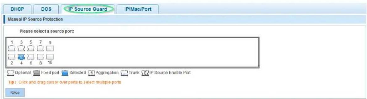
| Item | Description |
| Please select the IP source to protect the port: | Select the port (or ports) that you wish to protect by IP Source Guard. The example above shows that IP Source Guard is enabled for port 4. Note that IP Source Guard isn’t supported on Trunk or aggregated ports. |
![IP source protection port security configuration index source IP address source Mac address port Vlas ID aging time status operation new security port fist page prev page [1] next page last page1 / 1page](/content/2026/05/905137/images/38bfb301b2fd5b598bf546f210cc130cbac273b1931d5660f9289180705a5090.jpg)

![IP source protection port security configuration Index source IP address source Mac address port Vian ID aging time status operation 1 192.163.2:100 00:0A:95:9D:68:16 GiO/14 1=no limit(static new security port Initially page prev page [1] next page last page 1 /page](/content/2026/05/905137/images/aa89c606e3bb95667a4aaf97941c26751e66241a0ef4d89791bbabbe04f0a9ab.jpg)
| Item | Description |
| VLAN ID | Specify the VLAN ID for the static entry. Leave 1 for the default VLAN. |
| Source IP Address | Specify the IP address of the client for the static entry. |
| Source MAC Address | Specify the MAC address of the client for the static entry. |
| Ports | Select the port to which the client is connected (port 14 in the example above). You can only select one port. |
6.5.1.4 IP MAC Port Binding
The Intellinet Network Solutions 8-Port Gigabit Ethernet PoE+ Web-Managed Switch features IP MAC Port Binding. This powerful authentication function ensures correctness of hardware (MAC address), software/user (IP address) and location (Connected port) for devices connected to the network. This feature ensures they all are legal sources to prevent the data leakage from hackers faking the legal network devices.
![DHCP DOS IP Source Guard IP/Mac/Port Test list Binding enable □ □ mac address ip address Port number □ 5C:25.0A:02.BE:14 192.168.2.100 5 □ D4:A4:25:00:03.BE 192.168.1.10 15 first page prev page [1] next page last page 1 / 1page Scanning Binding](/content/2026/05/905137/images/ad505d9afab07b3496f4ef4b93714fdad199c7a5d40fa1b19db21ed828050416.jpg)
(screen shots taken from 16-port version)
| Application List | |||
| ☐ | mac address | ip address | Port number |
| ☐ | D4:A4:25:00:03:BE | 192.168.1.10 | 15 |
| ☐ | 5C 26:0A:02:8B:14 | 192.168.2.100 | 5 |
| Delete option first page prev page [1] next page last page 1 /page | |||
| Item | Description |
| Binding Enable | Check to activate IP Mac port binding. |
| Scanning | Click to scan for connected network clients. |
| Binding | Select the clients you wish to add to the IP Mac port binding table, then click on "Binding." |
| Application List | All current, static IP-MAC-port binding entries are listed here. Note that this information will be lost after the switch is restarted. |
6.5.2 Channel Detection
Fault/Safety
- Anti Attack
- Channel Detection
- ACL
The Intellinet Network Solutions switch is equipped with a set of network tools that can aid the network administrator in troubleshooting problems.
6.5.2.1 Ping

| Item | Description |
| Destination IP address | IP address you wish to ping. |
| Timeout Period | Define the maximum allowed response time(s) before the response is considered to have timed-out. |
| Repeat number | Define how many ping requests you want the Intellinet Network Solutions switch to send to the destination IP address. |
6.5.2.2 Tracert

| Item | Description |
| Destination IP address | IP address you wish to run a tracert for. |
| Timeout Period | Define the maximum allowed response time(s) before the response is considered to have timed-out. |
6.5.2.3 Cable Test
The cable test utility allows an administrator to perform a quick check of the connected cables.
![Ping Tracert Cable Test Please select port to configure: 1 3 5 7 2 4 6 8 Optional Fixed port Selected Aggregation Trunk Start Result Port Status 7 Normal first page prev page [1] next page last page1 / 1 page](/content/2026/05/905137/images/996ffb8a81c286b26540713db545188db2fce7658952502e007baa7529e25f2b.jpg)
| Item | Description |
| Select Port | Select one of the 10 ports, and then click on "Start test." |
| Test Results | Displays the results of the cable test. Note that if you test a port to which no cable is connected, the test returns the value "circuit breaker," because why not? |
6.5.3 ACL Access Control List
ACE is an acronym for Access Control Entry. It describes access permission associated with a particular ACE ID. There are three ACE frame types—Ethernet Type, ARP and IPv4—and two ACE actions—permit and deny. The ACE also contains many detailed, different-parameter options that are available for individual application.
ACL is an acronym for Access Control List, a table of ACEs that contain access control entries, which specify individual users or groups who are permitted or denied access to specific traffic objects such as a process or a program. Each accessible traffic object contains an identifier to its ACL. The privileges determine whether there are specific traffic object access rights.
ACL implementations can be quite complex (e.g., when the ACEs are prioritized for various situations). In networking, the ACL refers to a list of service ports or network services that are available on a host or server, each with a list of hosts or servers who are permitted or denied access to the service. ACL can generally be configured to control inbound traffic, and in this context, they are similar to firewalls.
6.5.3.1 Timetables
This section allows you to set up a time frame. This time frame can be applied to ACL rules to either allow or deny access. The timetable does not directly specify whether access is denied or allowed. Rather, it is simply a way to create an easily accessible time frame that can be applied to ACL rules. The example below shows the setup of a timetable called "WorkingHours." Note that the Intellinet Network Solutions switch must be set up with a proper system time (see section System Config).

![Save Timetable List: WorkHours Day Time Interval Edit / Delete Monday Tuesday Wednes day Thursday Friday 07:00-12:00 Monday Tuesday Wednes day Thursday Friday 13:00-19:00 Delete Timetable List Selection first page prev page [1] next page last page: / 1 page](/content/2026/05/905137/images/239bb9e60ba365fa0d3f540c8aebb31acd08c432a88e5c38d83e748c65ae2a89.jpg)
| Item | Description |
| New Timetable Name | Provide a descriptive name for the timetable. |
| Time Interval | Specify the days of the week and start and end time. Click on the + to add additional time frames. Click "Save" to save the timetable. |
| Timetables list | Drop-down list contains all timetables previously set up. |
| Time week | Selected weekdays for the selected timetable. |
| Time Interval | Time interval for selected timetable. |
Operation

Edit selected timetable

Deled selected timetable
6.5.3.2 ACL
This section describes how to set up the actual access control list (ACL). The ACL connects IP address and port information with a timetable (see section 6.5.3.1) and an action to either allow or deny access to the network through the switch. The example below creates an ACL, which allows access to the network for any computer

| Item | Description |
| ACL Number | Each ACL rule gets a number. Select the one from the drop-down list for which you want to create this ACE (Access Control Entry). |
| Action | Define whether this rule grants access ("allow") to the network, or prohibits it ("deny"). |
| SRC/DEST IP Address | Specify the source and destination IP address for this ACE. You can provide a single IP address (e.g., 192.168.2.100) or a specific network (e.g., 255.255.255.0). |
| SRC/DEST Port | This option is only visible if the ACE is created for TCP or UDP. It will not show for IP ACLs (see next parameter). You can provide a single port or a range of ports. |
| Protocol Matching | IP: The ACE is applied to packets based on their source and/or destination IP address.TCP/UDP: The ACE is applied to packets based on their source and/or destination IP address and the port number for the selected protocol. |
| Time | If you want to limit the ACE to a specific timetable (see section 6.5.3.1), select it from the drop-down list. |
Example 1 – Disallow access to the network for any computer outside of the working hours.

Example 2 – Disallow access to the network for an individual IP address during the working hours.

6.5.3.3 Apply ACL
This function allows an administrator to link an ACL to one or more of the 10 available switch ports.

Select the ports and ACL list, and click "Save" in order to activate.
6.6 PoE
The Intellinet Network Solutions 8-Port Gigabit Ethernet PoE+ Web-Managed Industrial Switch with 2 SFP Ports is equipped with sophisticated PoE-monitoring and configuration options.
6.6.1 PoE Config
PoE
- PoE Config
- PoE Port Config
- PoE Delay Config
6.6.1.1 Management
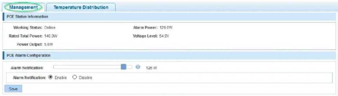
| Item | Description |
| Working status | Displays the value "On-line," indicating that the PoE function is working properly. |
| Rated total power | This number represents the maximum available PoE power for all connected PoE devices. |
| Power Output | This value represents the total power draw of all connected PoE devices. |
| Alarm Power | The Intellinet Network Solutions switch can alert the network administrator via SNMP messages if a certain PoE power draw value has been reached. This threshold can be configured under the alarm-notice. |
| Voltage Level | Displays the current output voltage. |
| Alarm-Notification | Define the alarm notice value, which, when exceeded, causes the switch to send out SNMP trap messages. |
| Alarm-Notification | Enable to receive SNMP traps if the threshold level has been exceeded. |
6.6.1.2 Temperature Distribution
![Management Temperature Distribution Temperature Config Temperature Alarm Threshold: 110°C Save Chip Temperature List Chip Number Current Temperature Alarm Threshold Edit 1 54°C 110°C first page prev page [1] next page last page1 /1 page](/content/2026/05/905137/images/2e44aa689ef15ac836290bcf4496bfeb5ef52baf2153994ea3cb659f92d777ed.jpg)
This function monitors the temperature of the two PoE chips in the Intellinet Network Solutions switch and sends out SNMP trap messages if a threshold you set will be exceeded.
Click in order to edit the temperature threshold of the PoE chip. Note that in order for the Intellinet Network Solutions PoE switch to send our SNMP traps, SNMP must be activated and configured.
6.6.2 PoE Port Config
This section describes how to edit the parameters of individual PoE ports.
PoE
- PoE Config
- PoE Port Config
- PoE Delay Config
Upon opening the configuration screen, an overview of the PoE ports and their statuses appears. Click on
in order to modify individual ports. Click on in order to modify the parameters for all ports on the current page (1-8) at the same time.

| Item | Description |
| Port ID | Displays the ID of the port you are editing or "CurPage All ports" if you are editing all ports on the current page. |
| Port Mode | Activate or deactivate PoE support. |
| Port Priority | You can choose from three values: low, mid and high. The priority can be used to define which port won't be receiving power in the event that the maximum PoE power has been exceeded.Example: It's possible to set the value to "high" for ports with security cameras connected to them. This ensures that these cameras will always be supplied with power, even if the total power draw on the Intellinet Network Solutions switch exceeds the maximum available PoE power. Ports that are set to low or mid will be disconnected first – in that order. |
| Detection Mode | Some good advice is to leave this AT&AF. You can enable AF-only mode, if your older IEEE802.3af PoE devices are not able to communicate with the Intellinet Network Solutions PoE switch. |
| Maximum Power | Define the maximum output power available for the port(s) in range from 1 to 36 watts. |
6.6.3 PoE Delay Config
PoE
- PoE Config
- PoE Port Config
- PoE Delay Config
This function allows an administrator to program a startup sequence for your PoE-compliant devices and eliminate potential problems caused by the increased power draw at startup. The sequential power-up guarantees a smooth startup procedure for all connected networking devices (i.e., your PoE-enabled network cameras).
PoE Delay
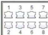
Optional Fixed port Selected Aggregation Trunk IP Source Enable Port
Tip: Click and drag cursor over ports to select multiple ports

Save settings
| Item | Description |
| Port Restart Time | This function is not directly linked to the port delay time, but in very special circumstances, it can be useful. If enabled, you can instruct the PoE switch to cut power to the port(s) after a given time has passed.Example 1 – Restart the PoE device once per week: |
| Port Restart Time: 7 Days 0 Hours 0 Minutes * | |
| Example 2 – Restart the PoE device once every 2.5 days: | |
| Port Restart Time: 2 Days 12 Hours 0 Minutes * | |
| Attention:you cannot set the exact time at which the restart occurs. It is controlled by when the feature was activated or when the switch has performed a restart. Be careful using this feature. | |
| Port Delay Time | Define how long the switch will have to wait before it activates the port(s) after a system restart. Enter the delay value in seconds. |
6.7 SPANNING TREE PROTOCOL (STP)
The Spanning Tree Protocol can be used to detect and disable network loops and to provide backup links between switches, bridges or routers. This allows the switch to interact with other bridging devices in your network to ensure that only one route exists between any two stations on the network. It also provides backup links, which automatically take over when a primary link goes down. The spanning tree algorithms supported by this switch include these versions:
• STP – Spanning Tree Protocol (IEEE 802.1D)
• RSTP – Rapid Spanning Tree Protocol (IEEE 802.1w)
• MSTP – Multiple Spanning Tree Protocol (IEEE 802.1s)
The IEEE 802.1D Spanning Tree Protocol and IEEE 802.1w Rapid Spanning Tree Protocol allow for the blocking of links between switches that form loops within the network. When multiple links between switches are detected, a primary link is established. Duplicated links are blocked from use and become standby links. The protocol allows the duplicate links to be used in the event of a failure of the primary link. Once the Spanning Tree Protocol is configured and enabled, primary links are established, and duplicated links are blocked automatically. The reactivation of the blocked links (at the time of a primary link failure) is also accomplished automatically without operator intervention. This automatic network reconfiguration provides maximum uptime to network users. However, the concepts of the Spanning Tree Algorithm and protocol are a complicated and complex subject and must be fully researched and understood. It is possible to cause serious degradation to network performance if the Spanning Tree is incorrectly configured. Please read the following before making any changes from the default values.
The Switch STP performs the following functions:
- Creates a single spanning tree from any combination of switching or bridging elements.
- Creates multiple spanning trees – from any combination of ports contained within a single switch in user specified groups.
- Automatically reconfigures the spanning tree to compensate for the failure, addition or removal of any element in the tree.
- Reconfigures the spanning tree without operator intervention.
Bridge Protocol Data Units
For STP to arrive at a stable network topology, the following information is used:
• The unique switch identifier
- The path cost to the root associated with each switch port
- The port identifier
STP communicates between switches on the network using Bridge Protocol Data Units (BPDUs). Each BPDU contains the following information:
• The unique identifier of the switch that the transmitting switch currently believes is the root switch
- The path cost to the root from the transmitting port
• The port identifier of the transmitting port
The switch sends BPDUs to communicate and construct the spanning-tree topology. All switches connected to the LAN on which the packet is transmitted will receive the BPDU. The switch does not directly forward BPDUs, but the receiving switch uses the information in the frame to calculate a BPDU, and, if the topology changes, initiates a BPDU transmission.
The communication between switches via BPDUs results in the following:
• One switch is elected as the root switch
• The shortest distance to the root switch is calculated for each switch
- A designated switch is selected. This is the switch closest to the root switch through which packets will be forwarded to the root.
- A port for each switch is selected. This is the port providing the best path from the switch to the root switch.
- Ports included in the STP are selected.
Creating a Stable STP Topology
If all switches have STP enabled with default settings, the switch with the lowest MAC address in the network will become the root switch. By increasing the priority (lowering the priority number) of the best switch, STP can be forced to select the best switch as the root switch. When STP is enabled using the default parameters, the path between source and destination stations in a switched network might not be ideal. For instance, connecting higher-speed links to a port that has a higher number than the current root port can cause a root-port change.
STP Port States
BPDUs take some time to pass through a network. This propagation delay can result in topology changes where a port that transitioned directly from a Blocking state to a Forwarding state could create temporary data loops. Ports must wait for new network topology information to propagate throughout the network before starting to forward packets. They must also wait for the packet lifetime to expire for BPDU packets that were forwarded based on the old topology. The forward delay timer is used to allow the network topology to stabilize after a topology change. In addition, STP specifies a series of states a port must transition through to further ensure that a stable network topology is created after a topology change.
Each port on a switch using STP exists is in one of the following five states:
- Blocking – the port is blocked from forwarding or receiving packets
- Listening – the port is waiting to receive BPDU packets that may tell the port to go back to the blocking state
- Learning – the port is adding addresses to its forwarding database, but not yet forwarding packets
• Forwarding – the port is forwarding packets - Disabled – the port only responds to network management messages and must return to the blocking state first
A port transitions from one state to another as follows:
• From initialization (switch boot) to blocking
• From blocking to listening or to disabled
• From listening to learning or to disabled
• From learning to forwarding or to disabled
• From forwarding to disabled
• From disabled to blocking

flowchart
graph TD
    A["Switch"] --> B["Blocking"]
    B --> C["Listening"]
    C --> D["Leaming"]
    D --> E["Forwarding"]
    E --> F["Disable"]
    F --> A
    C --> F
It's possible to modify each port state by using management software. When you enable STP, every port on every switch in the network goes through the blocking state and then transitions through the states of listening and learning at power up. If properly configured, each port stabilizes to the forwarding or blocking state. No packets (except BPDUs) are forwarded from or received by STP enabled ports, until the forwarding state is enabled for that port.
The Switch allows for two levels of operation: the switch level and the port level. The switch level forms a spanning tree consisting of links between one or more switches. The port level constructs a spanning tree consisting of groups of one or more ports. The STP operates in much the same way for both levels.
6.7.1 MSTP Region
MSTP
• Mstp Region
- Mstp Bridge
Mstp Region Configuration
Region name: DEADBEEF0102 (1 to 32 characters)
Revision Level: 0 (0 to 65535.default 0)
Save
Instance Mapping
Instance ID: 1
Vlan ID: For example: 1,3,5,7-10
Save
Delete
| Item | Description |
| MSTP Region Configuration | Each switch running MST in the network has a single MST configuration that consists of these two attributes:1. Region namea. An alphanumeric configuration name2. Revision Level |
| Instance Mapping | A table that associates each of the potential 4096 VLAN IDs to a given instance. |
6.7.2 MSTP Bridge

| Item | Description |
| Instance Priority | Priority can be configured for a specified instance. |
| Instance ID | Select the instance ID for which you want to define a priority. |
| Priority | Select the priority level for the instance ID. |
| Enable | Enable / disable STP. |
| Mode | STP – Spanning Tree Protocol (IEEE 802.1D)RSTP – Rapid Spanning Tree Protocol (IEEE 802.1w)MSTP – Multiple Spanning Tree Protocol (IEEE 802.1s) |
| Hello-Time | The hello timer is the time interval between each Bridge Protocol Data Unit (BPDU) that is sent on a port. The default hello timer is 2 seconds. Adjust the Spanning Tree Protocol (STP) hello timer to any value between 1 and 10 seconds. |
| Forward Delay | The forward delay timer is the time interval that is spent in the listening and learning state. The default forward delay timer is 10 seconds. Set the Spanning Tree Protocol (STP) forward delay timer to any value between 4 and 30 seconds. |
| MAX Age | The max age timer controls the maximum length of time interval that an STP switch port saves its configuration Bridge Protocol Data Unit (BPDU) information. The default max age timer is 10 seconds. Adjust the max age timer to any value between 6 and 40 seconds. |
| MAX Hops | For Multiple Spanning Tree Protocol (MSTP), configure the maximum number of hops a BPDU can be forwarded in the MSTP region. The default value is 10. Possible values range from 1 to 40. |

| Item | Description |
| Instance | Select the instance ID. |
| Port Fast | The time the Spanning Tree Protocol (STP) takes to transition ports over to the forwarding state can cause problems like delays when client computers connect to switches. Port-fast solves the problem by effectively preventing the implementation of STP on that port. |
| Auto Edge | By default, "auto-edge" is enabled on all ports. This will look for BPDUs for 3 seconds and, if none are found, will begin forwarding packets, and the port is set as "edge." If there are BPDUs, the port is set as "non-edge." |
| BDPU Guard | BPDU guard disables the port upon BPDU reception if port-fast is enabled on the port. This effectively denies devices connected to these ports from participating in the designed STP, thus protecting your data-center core. |
| BPDU Filter | Enabling BPDU filtering for a port stops sending or receiving BPDU on this interface; this is the same as disabling spanning tree on the interface. It is a risky choice, unless you are sure that no switch can ever be connected to this port. |
| TC Guard | In certain situations, it may be desirable to prevent ports from propagating topology changes to the rest of the network. This may be the case when the network is not under a single administrative control and it is beneficial to prevent devices external to the core of the network from causing MAC-address flushing in the core. Enable this by configuring Topology Change Guard (TC Guard) on the port. |
| Priority | If a loop occurs in the network, MSTP uses the port priority parameter when it selects an interface to put into the forwarding state. Assign higher priority values (lower numbers) to interfaces that you want selected first and lower priority values (higher numbers) that you want selected last. If all interfaces have the same priority value, MSTP puts the port with the lowest interface number in the forwarding state and blocks the other ports. |
| Path Cost | The MSTP path cost default value is derived from the media speed of an interface. If a loop occurs, MSTP uses cost when selecting an interface to put in the forwarding state. Assign lower cost values to interfaces that you want selected first and higher cost values that you want selected last. If all interfaces have the same cost value, MSTP puts the interface with the lowest interface number in the forwarding state and blocks the other interfaces. |
| Point to Point | Admin Point-to-Point Link--Specify whether this port is connected to a shared LAN segment (value "off") or a point-to-point LAN segment (value "on"). A point-to-point LAN segment is connected to exactly one other bridge (normally with a direct cable between them). Only point-to-point links and edge ports can rapidly transition to the forwarding state. If you set this value to "auto," the switch automatically detects whether the port is connected to a shared link or a point-to-point link. |
| Rootguard | Root-guard ensures that an unintended switch does not become a new root bridge. Root guard allows the device to participate in STP as long as the device does not try to become the root. If root guard blocks the port, subsequent recovery is automatic. Recovery occurs as soon as the offending device ceases to send superior BPDUs. |
| TC Ignore | Ignore technology change (TC) on or off. |
6.8 DHCP RELAY AGENT
A DHCP client is an Internet host using DHCP to obtain configuration parameters such as an IP address. A DHCP relay agent is any host that forwards DHCP packets between clients and servers. Relay agents are used to forward requests and replies between clients and servers when they are not on the same physical subnet. The Intellinet Network Solutions switch can fulfill the role of such a relay agent.
DHCP RELAY
- Dhcp Relay
option82
6.8.1 DHCP Relay

| Item | Description |
| DHCP relay enable | Enable or disable DHCP relay. |
| DHCP OPTION trust field enable: | When enabled, the client that receives the DHCP message with option82 information will forward it; otherwise, it will be discarded. |
| DHCP Server IP | Provide the IP address of the DHCP server, and click "add." |
6.8.2 Option82
DHCP RELAY
- Dhcp Relay
option82
6.8.2.1 Circuit Control
![Option82 Config Circuit Control Proxy Remote IP Address Circuit Control:___________________* VLAN ID:___________________ Save Number Circuit Name Circuit ID VLAN ID Edit / Delete first page prev page [1] next page last page 1 /1 page](/content/2026/05/905137/images/874adeac54fdbe5d3a97167e03cd3222b5828aeb1f450d611f4fce08d4aec121.jpg)
| Item | Description |
| Circuit Control | Provide the circuit ID number. Possible values range from 3 to 63. |
| VLAN ID | Type in the VLAN ID. Use value 1 for the default VLAN. |
6.8.2.2 Proxy Remote
![Option82 config Circuit control Proxy remote IP address Proxy remote: _________* VLAN ID: _________* Add Serial number Proxy remote name Proxy remote ID VLAN ID Operation first page prev page [1] next page last page 1 / 1page](/content/2026/05/905137/images/bc602c9643398acca3f9cf18e18290d8d47f3d21fe76376af76e620f5798ac00.jpg)
| Item | Description |
| Proxy Remote | ASCII Remote ID string, up to 63 characters. |
| VLAN ID | Type in the VLAN ID. Use value 1 for the default VLAN. |
6.8.2.3 IP Address
![Option82 config Circuit control Proxy remote IP address IP address: Add VLAN ID: Serial number IP address VLAN ID Operation first page prev page [1] next page last page 1 / 1page](/content/2026/05/905137/images/e182e67e8b2b894220c8d0cf1abb5cc3f76ccd55b0d47f776cf11dd25c4e2d7b.jpg)
| Item | Description |
| IP Address | IP address of DHCP server. |
| VLAN ID | Type in the VLAN ID. Use value 1 for the default VLAN. |
6.9 DHCP SERVER
The Dynamic Host Configuration Protocol (DHCP) is a standardized network protocol used on Internet Protocol (IP) networks for dynamically distributing network configuration parameters such as IP addresses for interfaces and services. A typical DHCP server is a router or a Windows server. The Intellinet Network Solutions 8-Port Gigabit Ethernet Web-Managed Switch can also fulfill the role of a DHCP server.

flowchart
graph TD
    A["Computer"] -->|192.168.0.77| B["DHCP Server"]
    C["Computer"] -->|192.168.0.13| B
    D["Computer"] -->|192.168.0.22| B
    B --> E["IP Address Database"]
6.9.1 DHCP Config
DHCPserver
- Dhcp Config
6.9.1.1 Enable Config
Set this option to "Open" in order to activate the DHCP server function. Note that when you want to use the DHCP Server function, you cannot use the DHCP relay feature (see section 6.8 DHCP Relay Agent) at the same time.
6.9.1.2 Pool Config
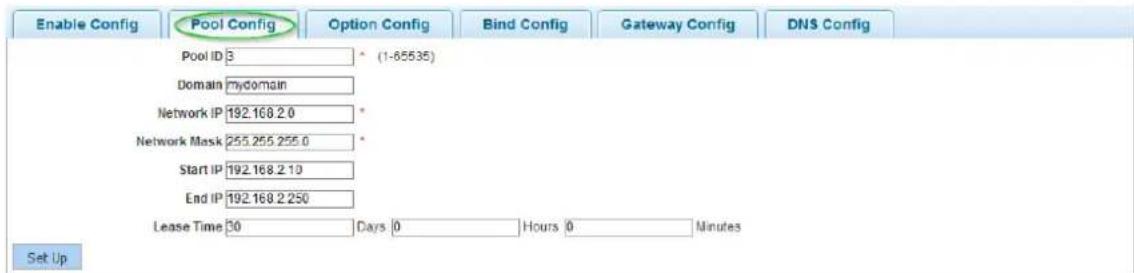
| Item | Description |
| Pool ID | Identifies the dynamic address pool from which the DHCP requests are served. |
| Domain | If you are on a domain network, the domain name should go here. |
| Network IP | This is the first IP address of the subnet ending in ".0". It can't be assigned to an actual network client. |
| Network Mask | Provide the network mask of choice for your network. |
| Start IP | Define the lowest IP address of the IP address pool. |
| End IP | Define the highest IP address of the IP address pool. |
| Lease Time | Defines how long the client is allowed to keep the IP address. When the time has elapsed, the switch will issue a new IP address to the client. |
Note: The DHCP IP address range must be in the same range as the Intellinet Network Solutions switch's LAN IP range (e.g., 192.168.2.xxx).
6.9.1.3 Option Config
This page allows modification of the DHCP options, as stated in RFC2132. The example below shows how to specify a specific NTP server.

| Item | Description |
| Pool ID | Identifies the dynamic address pool from which the DHCP requests are served. |
| Code | Possible values are – to 255. These are the codes or tags per RFC2132. |
| Code Value Type | hexhexasciiipSelect the appropriate value (i.e., select IP if you enter an IP address in the code value field below). |
| Code Value | Provide the value for the tag (code) you selected. |
6.9.1.4 Bind Config
![Enable Config Pool Config Option Config Bind Config Gateway Config DNS Config Bind List IP Adress Hardware Type Hardware Adress Expire time Operate 192.168.2.10 Ethernet 08:00:0t67.8c.ca 0Day 23Hour 59Min 192.168.2.11 Ethernet 5c.26.0a.02.8b.14 0Day 23Hour 12Min first page prev page [1] next page last page 1 / 1page](/content/2026/05/905137/images/83fcec0707fedb7cfad114e092a67eefb51b606d0ec54e0b621163054964b737.jpg)
This page displays all clients that have obtained an IP address from the Intellinet Network Solutions switch.
Click on to set the lease time to expired, which forces the connected client to obtain a new IP address instantly.
6.9.1.5 Gateway Config

On this page, provide the Gateway IP address that you wish to provide to the DHCP clients.
6.9.1.6 DNS Config

On this page, provide the DNS IP address(es) that you wish to provide to DHCP clients.
6.10 IGMP SNOOPING
The Internet Group Management Protocol (IGMP) lets hosts and routers share information about multicast group memberships. IGMP snooping is a switch feature that monitors the exchange of IGMP messages and copies them to the CPU for future processing. The overall purpose of IGMP Snooping is to limit the forwarding of multicast frames to only ports that are a member of the multicast group.
Computers and network devices that want to receive multicast transmissions need to inform nearby routers that they will become members of a multicast group. The Internet Group Management Protocol (IGMP) is used to communicate this information. IGMP is also used to periodically check the multicast group for members that are no longer active. In the case where there is more than one multicast router on a sub network, one router is elected as the "queried." This router then keeps track of the membership of the multicast groups that have active members. The information received from IGMP is then used to determine if multicast packets should be forwarded to a given sub network or not. Using IGMP, the router can check to see if there is at least one member of a multicast group on a given sub network. If there are no members on a sub network, packets will not be forwarded to that sub network.
Multicast Service

flowchart
graph TD
    A["IPTV Server"] --> B["Switch"]
    B --> C["Router"]
    C --> D["Switch"]
    D --> E["Switch"]
    E --> F["Switch"]
    F --> G["Switch"]
    G --> H["Switch"]
    H --> I["Switch"]
    I --> J["Switch"]
    J --> K["Switch"]
    K --> L["Switch"]
    L --> M["Switch"]
    M --> N["Switch"]
    N --> O["Switch"]
    O --> P["Switch"]
    P --> Q["Switch"]
    Q --> R["Switch"]
    R --> S["Switch"]
    S --> T["Switch"]
    T --> U["Switch"]
    U --> V["Switch"]
    V --> W["Switch"]
    W --> X["Switch"]
    X --> Y["Switch"]
    Y --> Z["Switch"]
    Z --> AA["Switch"]
    AA --> AB["Switch"]
    AB --> AC["Switch"]
    AC --> AD["Switch"]
    AD --> AE["Switch"]
    AE --> AF["Switch"]
    AF --> AG["Switch"]
    AG --> AH["Switch"]
    AH --> AI["Switch"]
    AI --> AJ["Switch"]
    AJ --> AK["Switch"]
    AK --> AL["Switch"]
    AL --> AM["Switch"]
    AM --> AN["Switch"]
    AN --> AO["Switch"]
    AO --> AP["Switch"]
    AP --> AQ["Switch"]
    AQ --> AR["Switch"]
    AR --> AS["Switch"]
    AS --> AT["Switch"]
    AT --> AU["Switch"]
    AU --> AV["Switch"]
    AV --> AW["Switch"]
    AW --> AX["Switch"]
    AX --> AY["Switch"]
    AY --> AZ["Switch"]
    AZ --> BA["Switch"]
    BA --> BB["Switch"]
    BB --> BC["Switch"]
    BC --> BD["Switch"]
    BD --> BE["Switch"]
    BE --> BF["Switch"]
    BF --> BG["Switch"]
    BG --> BH["Switch"]
    BH --> BI["Switch"]
    BI --> BJ["Switch"]
    BJ --> BK["Switch"]
    BK --> BL["Switch"]
    BL --> BM["Switch"]
    BM --> BN["Switch"]
    BN --> BO["Switch"]
    BO --> BP["Switch"]
    BP --> BQ["Switch"]
    BQ --> BR["Switch"]
    BR --> BS["Switch"]
    BS --> BT["Switch"]
    BT --> BU["Switch"]
    BU --> BV["Switch"]
    BV --> BW["Switch"]
6.10.1 IGMP Config
IGMP
- lgmp Config
- Igmp Filter Policy...
6.10.1.1 IGMP Config Options
IGMP Config
IGMP Port Config
IGMP VLAN Config
IGMP config options
Open IGMP Snooping : □
Forwarding mode: MAC
Filtering mode: □
Query mode: □
Query interval: □
Unknow group suppression: Flood
Default policy: Allow
Query response time: 60 * ([1-65535] s)
Query response interval: 100 * ([1-65535] 1/10s)
Multicast aging time: 260 (10-300) s
Apply
| Item | Description |
| Open IGMP Snooping | Activate to enable IPMP snooping. |
| Forwarding mode | Select the forwarding mode to be either IP-based or MAC-based. |
| Filtering mode | Enable or disable IGMP filtering. |
| Query mode | Enable or disable the MLD querier function. |
| Query interval | Enable MLD snooping (Multicast Listener Discovery) for IPv6. |
| Unknown group suppression | Flood: Unknown multicast data is flooded.Drop: Unknown multicast data is dropped. |
| Default policy: | Set the default policy to either "Allow" or "Refuse". |
| Query response time | Define the time in seconds. |
| Query response interval | Define the interval in 1/10^th of a second. |
| Multicast aging time | Define the multicast aging time in seconds. |
6.10.1.2 IGMP Port Config

| Item | Description |
| Maximum multicast number | Type in the multicast number from 1 - 254. |
| Policy | Assign a policy (strategy). |
6.10.1.3 IGMP LAN Config
![IGMP Config IGMP Port Config IGMP VLAN Config IGMP VLAN config options VLAN: 1 IGMP Snooping VLAN: IGMP Snooping Leave Query: IGMP Snooping Dynamic Learn: IGMP Snooping Querier: Querier version 2 Querier IP 0.0.0.0 Querier Max-Response time: 10 * ([1-18000] s) Querier Response Interval: 60 * ([1-25] s) Querier timeout: 125 * ([60-300] s)](/content/2026/05/905137/images/6eb78975822c33c6b97c8dea414b0e7e7701abac5dd1fe11cf56dd7e1c188f8c.jpg)
| Item | Description |
| VLAN | Select the VLAN ID for which you wish to enable IGMP snooping. |
| IGMP Snooping VLAN | Click to enable IGMP Snooping for the above VLAN ID. |
| IGMP Snooping Leave Query | Set IGMP snooping fast-leave. |
| IGMP Snooping Dynamic Learn | Dynamically learn the IP multicast groups through IGMP snooping. |
| IGMP Snooping Querier | In networks/VLANs do not have a router that can take on the multicast router role and provide the mrouter (static multicast router) discovery on the switches, turn on the IGMP snooping querier feature. |
| Querier version | Defines the querier version. 2=IGMPv2, 3 = IGMPv3. |
| Querier IP | Snooping querier on an interface when there is no multicast router in the VLAN to generate queries. |
| Querier Max-Response time | Define the time in seconds. |
| Querier Response Interval | Define the time in seconds. |
| Querier timeout | Define the time in seconds. |
6.10.2 IGMP Filter Policy Config
![Multicast filtering strategy configuration Create a new strategy Select the existing strategy New policy name: Default policy: Allow Refuse Multicast IP address: Mask: Mode: Refuse Save configuration Filter strategy list: address mask mode operation delete strategy first page prev page [1] next page last page 1 / 1 page](/content/2026/05/905137/images/16c4ca4cd7048d713f2866f76744fec0781319f748383f6f25ad559b5ac96fb8.jpg)
| Item | Description |
| Create a new strategy | Select this if you wish to set up a new strategy. |
| Select the existing strategy | Select this in order to edit a strategy previously set up. |
| Default policy | Set to either allow or refuse. |
| Multicast IP address | IPv4 addresses that are reserved for IP multicasting and registered with the Internet Assigned Numbers Authority (IANA). For example, 224.0.0.1 = all hosts on the same network segment; 224.0.0.13 = Protocol Independent Multicast (PIM) Version 2. Possible values range from 224.0.0.0 through 239.255.255.255. |
| Mask | Provide the network mask. |
| Mode | Set to either allow or refuse. |
6.11 TERMINAL ACCESS CONTROLLER ACCESS-CONTROL SYSTEM (TACACS+)
TACACS+
TACACS+ Config
Terminal Access Controller Access-Control System (TACACS, usually pronounced like "tack-axe") refers to a family of related protocols that handle remote authentication and related services for networked access control
through a centralized server. The original TACACS protocol, which dates back to 1984, was used for communicating with an authentication server, common in older UNIX networks; it spawned related protocols. Terminal Access Controller Access-Control System Plus (TACACS+) is a protocol released as an open standard beginning in 1993. Although derived from TACACS, TACACS+ is a separate protocol that handles authentication, authorization and accounting (AAA) services. Compared to the open standard RADIUS authentication (section 6.12 Radius), TACACS+ encrypts the entire payload whereas RADIUS only encrypts passwords.
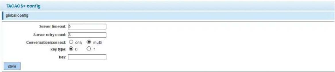
| Item | Description |
| Global Config | Global parameters that can be overwritten by port-specific configuration. |
| Server timeout | The global timeout interval determines how long the Intellinet Network Solutions switch waits for responses from TACACS+ servers before declaring a timeout failure. |
| Server retry count | Specifies the number of retry attempts that will be made to establish a Transmission Control Protocol (TCP) connection between a TACACS+ client and the TACACS+ server. The default value is 3. |
| Conversation / Connect | This parameter defines how many connections there will be between router daemon. Only: "single-connection" The daemon must support single-connection mode for this to be effective; otherwise, the connection between the network access server and the daemon will lock up or you will receive spurious errors. |
| Key type | 0: Key value in clear text format7: Key value is type-7 encrypted. |
| Key | Type in the key value. |

| Item | Description |
| Port Config | Global parameters that can be overwritten by port-specific configuration. |
| Server IP | IP Address for the TACSACS+ server. |
| Authentication port | Define the TCP port number of the TACSACS+ server connection. |
| Server timeout | The timeout interval determines how long the Intellinet Network Solutions switch waits for responses from a specific TACACS+ server before declaring a timeout failure. If left empty, the global server timeout value will be used; otherwise, the server timeout takes precedence. |
| Key type | 0: Key value in clear text format7: Key value is type-7 encrypted. |
| Key | Key value. |
6.12 RADIUS
RADIUS
• RADIUS Global C...
Remote Authentication Dial-In User Service (RADIUS) is a networking protocol that provides centralized Authentication, Authorization and Accounting (AAA or Triple A) management for users who connect and use a network service.
RADIUS is a client/server protocol that runs in the application layer and can use either TCP or UDP as transport. Network access servers, the gateways that control access to a network, usually contain a RADIUS client component that communicates with the RADIUS server. RADIUS is often the backend of choice for 802.1X authentication as well. The RADIUS server is usually a background process running on a UNIX or Microsoft Windows server.
6.12.1 Radius General Config
![RADIUS global config Server repeat number: 3 [1-100] Server timeout: 2 [1-1000] Server quiet time: 0 [1-1440] dead-criteria Retry count: 0 [1-100] dead-criteria timeout: 0 [1-120] save cancel](/content/2026/05/905137/images/6e7bd14c9beea1c35e7d8555db0486372c5606f424384d673f802fa8a2b9350e.jpg)
| Item | Description |
| Server repeat number | Specifies the number of retry attempts that will be made to establish a connection between a RADIUS client and the RADIUS server. The default value is 3. |
| Server timeout | The timeout interval determines how long the Intellinet Network Solutions switch waits for responses from RADIUS server before declaring a timeout failure. |
| Server quiet time | If the Intellinet Network Solutions switch is unable to authenticate the client, it will wait a specified amount of time before trying again. The amount of time is specified with the quiet-period parameter. Entered in minutes; max. 1440 minutes (24 hours). |
| Dead-criteria retry count | Set the number of times that the Intellinet Network Solutions switch does not receive a valid response from the RADIUS server before the server is considered unavailable. |
| Dead-criteria timeout | Set the time in seconds during which the Intellinet Network Solutions switch does not need to receive a valid response from the RADIUS server. The range is from 1 to 120 seconds. |
6.12.2 Radius Server Config
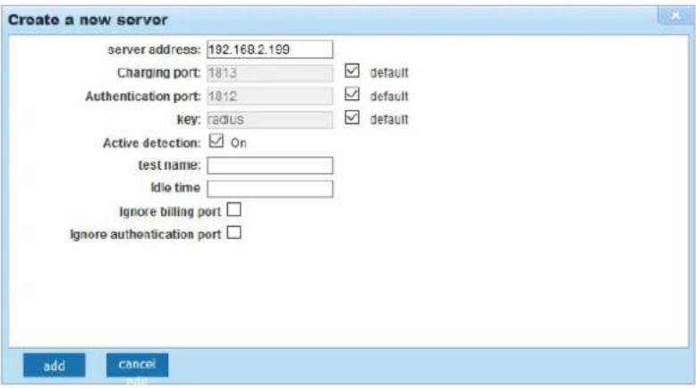
| Item | Description |
| Server address | Type in the address of the RADIUS server. |
| Charging port | Type the accounting port number on the RADIUS server's host computer.The default port number is 1813. |
| Authentication port | Type the accounting port number on the RADIUS server's host computer.The default port number is 1812. |
| Key | The key parameter in the radius-server command is used to encrypt RADIUS packets before they are sent over the network. The value for the key parameter on the Intellinet Network Solutions switch device should match the one configured on the RADIUS server. The default value is "radius". |
| Active detection | Enables or disables active detection of RADIUS server. |
| Test name | The username for active detection. |
| Idle time | The interval time for RADIUS security server send message on accessible state. The default value is 60 minutes. Possible values range from 0 to1440 minutes (24 hours). |
6.13 AAA
Authentication, authorization and accounting (AAA) is a system for tracking user activities on an IP-based network and controlling their access to network resources. AAA is often implemented as a dedicated server.
6.13.1 Enable Config

Enable or disable AAA.
6.13.2 Region Config

![Domain enable config Status: ON OFF Save ISP domain domain name: (1-30bytes) Status: block Verify that the user is carrying the domain name: without-domain Add ISP domain list domain name Status whether to carry domain name Binding scheme Oprotion default active without-domain first page prev page [1] next page last page 1 / 1page](/content/2026/05/905137/images/2fa866ed8c756679f4933c37ac4592340f351d7cd7d4dfc48a3a73c0206ef2b5.jpg)
| Item | Description |
| Domain name | Type in the name of the ISP domain. An Internet service provider (ISP) domain is a group of users who belong to the same ISP. For a username in the format of userid@isp-name or userid.isp-name, the isp-name following the "@" or "." character is the ISP domain name. The access device uses userid as the username for authentication, and isp-name as the domain name. |
| Status | Set to either "block" or "active." By default, an ISP domain is in the active state, which means that all the users in the domain are allowed to request network service. |
| Verify that the user ... | Verify that the user is carrying the domain name. |
6.14 QoS – QUALITY OF SERVICE
Quality of Service (QoS) is an advanced traffic prioritization feature that allows an administrator to establish control over network traffic. QoS enables you to assign various grades of network service to different types of traffic such as multimedia, video, protocol-specific, time critical, and file-backup traffic. QoS reduces bandwidth limitations, delay, loss, and jitter. It also provides increased reliability for delivery of your data and allows you to prioritize certain applications across your network. You can define exactly how you want the switch to treat selected applications and types of traffic.
You can use QoS on your system to control a wide variety of network traffic by:
• Classifying traffic based on packet attributes.
- Assigning priorities to traffic (for example, to set higher priorities to time-critical or business-critical applications).
- Applying security policy through traffic filtering.
- Providing predictable throughput for multimedia applications such as video conferencing or Voice over IP by minimizing delay and jitter.
- Improving performance for specific types of traffic and preserving performance as the amount of traffic grows.
- Reducing the need to constantly add bandwidth to the network.
• Managing network congestion.
6.14.1 QoS Rules

Despite the name "Remark" or "QoS Multi-Label," this section actually allows you to create your Quality of Service rules.
![QOS Multi-Label Rule Index: 1 Index Range (1-32) Operation Type: Equal Value Type: Source IP Value: 192.162.2.189 COS Mapping: 3 Priority Remark: 0 Choose Port to Config: 1 3 5 7 9 2 4 5 6 8 10 Optional Fixed port Selected Aggregation Trunk Tips Click and drag cursor over ports to select multiple ports Select all Select all others Cancel Save Cancel Rule List Rule Index Service Class Mapping Priority Remark Value Type Value Operation Type Port List Delete Delete All Rules first page prev page [1] next page last page / 1 page](/content/2026/05/905137/images/cf4833c746b6984b91dfa7faee38beab3193436114267c563dc3cd8f2446d5e4.jpg)
| Item | Description | |
| Rule Index | Key in the rule number. | |
| Operation type | Set to "Equal" or "Always match." | |
| Value type | This value defines the kind of value you intend to use for the QoS rule. | |
| Value | Key in the value that corresponds to the value type you selected above. | |
| CoS mapping | CoS stands for Class of Service. There are eight values to choose from. | |
| Priority remark | As an alternative to CoS mapping, you can define the priority value here, values 0-7. | |
| Choose port to config | Select the port or ports for the QoS rule. Select all ports if you want the rule to apply to whichever port the devices are connected. | |
6.14.2 Queue Config


In this section, you define which priority algorithm you wish the Intellinet Network Solutions switch to utilize.
| Item | Description |
| Queue mode | SP = Strict Priority, RR = Round Robin, WRR = Weighted Round Robin and WFQ = Weighted Fair Queuing. |
6.14.3 Queue Mapping
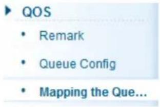
6.14.3.1 CoS-Queue-Map

This page allows the network administrator to classify CoS settings to traffic queues. The server ID represents the CoS (Class of Server) ID.
6.14.3.2 DSCP-CoS-Map

This allows network managers to determine the output queue that is assigned for a specific DSCP field. The server ID represents the DSCP field ID, and the QUEUE ID is listed as the server list on the screen.
6.14.3.3 Port-CoS-Map

This page allows the network administrator to classify CoS settings to the 10 physical ports on the Intellinet Network Solutions switch. The server ID represents the CoS (Class of Server) ID.
6.15 ADDRESS TABLE
To switch data packets between LAN ports efficiently, the Intellinet Network Solutions switch maintains an address table. When the switch receives a frame, it associates the media access control (MAC) address of the sending network device with the LAN port on which it was received. In doing so, the switch drastically cuts down on unnecessary network traffic because, instead of flooding all LAN ports of the same VLAN with the information, it only sends it to the port where the recipient is connected.
6.15.1 Address Table Config

6.15.1.1 MAC Add & Delete
The screen is divided into three sections.
![Address Table Config Mac add and delete Mac study and aging Mac filter clear MAC: Clear Mac addr list save 1 2 4 6 8 10 1 3 5 7 9 Optional Not optional Selected Aggregation Trunk Vlan: 1 (1-4094) Mac address : save MAC address list: all serial number MAC address VLAN ID address type port Aggregation group 1 08:00:0F:67:60.BC 1 dynamic 5 2 DE:AD:BE:EF:01:02 1 static Management 3 D4:A4:25:00:03:BE 1 dynamic 3 4 5C:26:0A:02:8B:14 1 dynamic 1 first page prev page [1] next page last page 1 / 1page](/content/2026/05/905137/images/fa1460989b09635e14b3cd3320138ae254a9149d6b21c3bd11ea54742559fdc5.jpg)
Section 1 ("clear Mac addr list") allows you to clear the MAC address table.

Section 2 can be used to manually enter a VLAN – MAC Address – Port pairing.
Section 3 displays all MAC addresses that are currently in the MAC address table.
6.15.1.2 MAC study & aging
This section allows the network administrator to specify the maximum amount of MAC addresses that can be learned per port. You can configure a maximum number of secure MAC addresses for each port. The default
interface maximum is 8191 addresses. Interface maximums cannot exceed the device maximum, which is also 8191.
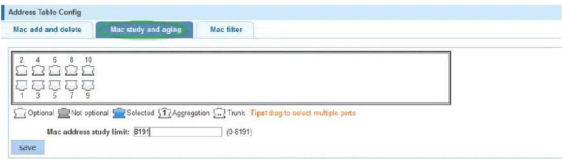
| Item | Description |
| Ports | Select one or multiple ports, for which you want to define the MAC address study limit |
| MAC address study limit | Key in the maximum MAC address limit for the selected port(s). |
The Intellinet Network Solutions switch also provides a mechanism to adjust the aging time for stored MAC addresses. The aging time controls how long the switch stores the MAC address in the MAC address table. Every time a client sends or receives traffic, the aging time for the client's MAC address is reset. If there is no traffic for a MAC address in a time frame that exceeds the time defined in the aging time, the MAC address is removed from the MAC address table. The default aging time is 300 seconds. Setting the value to "0" disables the aging time mechanism, which means that a MAC address that has been learned once will be kept in the MAC address table until the switch is reset. But since the Intellinet Network Solutions switch has only a finite amount of space to hold MAC addresses, it is recommended to keep the aging time at or around the default value.

6.15.1.3 MAC Filter
With this feature, the network administrator can prevent access to the network for selected MAC addresses and VLAN IDs (1 = default VLAN).
| Item | Description |
| MAC Address | Type in the MAC address that you want to block. |
| MAC address study limit | Type in the VLAN ID if applicable. |
6.16 SNMP
Simple Network Management Protocol (SNMP) is an OSI Layer 7 (Application Layer) designed specifically for managing and monitoring network devices. SNMP enables network management stations to read and modify the settings of gateways, routers, switches and other network devices. Use SNMP to configure system features for proper operation, monitor performance and detect potential problems in the switch, switch group or network.
6.16.1 SNMP Config

Activate or deactivate SNMP.
6.16.1.1 Community Config

| Item | Description |
| Community name | SNMP Community string. The SNMP read-only community string is like a password. It is sent along with each SNMP Get-Request and allows (or denies) access to device. |
| Access authority | Set to read-only or read-write. |
6.16.1.2 Group Config
The Intellinet Network Solutions switch uses a view-based access control model that allows the network administrator to configure the access privileges granted to a group.
![SNMP Config Community Config Group Config User Config Trap Config View Config SNMP group group name security level read view read and write view notify view operation new group delete select group first page: new page [1] next page: last page1 / 1page new group group name : * string length[1-16] Security level : no Authentication ar read view : none read and write view : none notify view : none save OUT](/content/2026/05/905137/images/c3796f92acf92b424aa88c16d335afbbd2f03720ed646515f74efd23220f95cd.jpg)
| Item | Description |
| Group name | Provide a group name. |
| Security level | Select the desired security level. |
| no Authentication ar √no Authentication and no encryptionAuthentication and no encryptionAuthentication and encryption | |
| Read viewRead and write viewNotify view | Assign the desired view (a view must be created first - see SNMP View Config). |
6.16.1.3 User Config
This section describes how to set up SNMP users and assign them to an SNMP group.
![SNMP Config Community Config Group Config User Config Trap Config edit SNMP user user name : ________ * string legth[1-16] Security level : Authentication and # group name : ________ Authentication mode : MD5 Authentication password ________ * string legth[8-60] Confirm Authentication password ________ encrypt mode DES Encrypted password ________ * string legth[8-60] Confirm save quit](/content/2026/05/905137/images/9990e884fb318fda2afaf20202c356681c3209c86447abf2a96d7e443920dcd6.jpg)
| Item | Description |
| User name | Provide a group name. |
| Security level | Select the desired security level.no Authentication arno Authentication and no encryptionAuthentication and no encryptionAuthentication and encryption |
| Group name | Provide a group name. |
| Authentication mode | Select the function of choice.MD5MD5SHA |
| Authentication password | Key in the password. |
| Encryption mode | Select either AES or DES to encrypt the password. |
| Encrypted password | Key in the encrypted password. |
6.16.1.4 Trap Config

| Item | Description |
| Destination IP Address | The IP address of the SNMP manager (TRAP viewer) |
| Address type | IPv4 (and perhaps later IPv6 will be supported) |
| Security name | When using security mode v3, you can select a user from a drop down list. That user was created in the SNMP user config. |
| UDP port number | Port for Simple Network Management Protocol Trap (SNMPTRAP). |
| Security mode | Select the security mode (V1, V2 or V3). |
6.16.1.5 View Config
SNMPv3 defines the concept of MIB views in RFC 3415, View-based Access Control Model (VACM) for SNMP. MIB views provide an agent with better control over who can access specific branches and objects within its MIB tree. A view consists of a name and a collection of SNMP object identifiers, which are either explicitly included or excluded. Once defined, a view is then assigned to an SNMP group - see SNMP Group Config.
![SNMP Config Community Config Group Config User Config Trap Config View Config view name View1 * string length[1-15] New view](/content/2026/05/905137/images/c4678aafdaf888e256c4db1d6fcc7034b5f22df52fdab052dce1e5ab175bceec.jpg)
Once a view has been created, create a rule for the view.
![View rule list View1 delete view rule MIB subtree OID New view rule Delete select View rule edit view rule Excluded is not effective for a subset of the excluded content, which is not valid for the included rule: ● contain ○ exclude MIB subtree OID : * String length[1-128] subtree mask: String length[1-31] save quit](/content/2026/05/905137/images/ce877c284699b8829594b898b042a192e8a453b87193f026bd4caa2d340e1ff6.jpg)
| Item | Description |
| Rule | Also referred to as the ""Type." Specifies whether to include or exclude the view subtree or family of subtrees from the MIB view. |
| MIB subtree OID | Enter an OID string for the subtree to include or exclude from the view. OID string is 256 characters in length. For example, the system subtree is specified by the OID string .1.3.6.1.2.1.1. |
| Subtree mask | Provide the OID mask here. |
6.16.2 RMON Config

Remote Monitoring (RMON) is a standard monitoring specification that enables various network monitors and console systems to exchange network-monitoring data. RMON is the most important expansion of the SNMP standard. RMON is a set of MIB definitions that is used to define standard network monitor functions and interfaces, enabling communication between SNMP management terminals and remote monitors. RMON provides a highly efficient method to monitor actions inside the subnets.
MID of RMON consists of 10 groups. The Intellinet Network Solutions 8-Port Gigabit Ethernet PoE+ Web-Managed Switch supports the most frequently used groups 1, 2, 3 and 9:
• Statistics: Collects Ethernet, Fast Ethernet, and Gigabit Ethernet statistics on an interface.
- History: Collects a history group of statistics on Ethernet, Fast Ethernet, and Gigabit Ethernet interfaces for a specified polling interval.
- Alarm: Monitors a specific management information base (MIB) object for a specified interval, triggers an alarm at a specified value (rising threshold) and resets the alarm at another value (falling threshold). Alarms can be used with events; the alarm triggers an event, which can generate a log entry or an SNMP trap.
- Event: Determines the action to take when an event is triggered by an alarm. The action can be to generate a log entry or an SNMP trap.
RMON is specified as part of the Management Information Base (MIB) in RFC1757 as an extension of the Simple Network Management Protocol (SNMP).
6.16.2.1 Statistics Group
![Statistics Group History Group Alarm Group Event Group count group list index interface name new count group delete select count group statistical group configuration index: _________ [1-65535] interface name: interface Gi0/1 owner: _________ string length[1-30] save quit](/content/2026/05/905137/images/7ee4e6d301d20e60253d21fdea85a536b1fb0e865e3972ee4660eedea356a515.jpg)
| Item | Description |
| Index | Specify the history table index number. |
| Interface name | Select one of the eighteen Gigabit ports from the drop-down list. |
| Owner | Optional field that allows the network administrator to enter the name of the owner of the Statistics RMON group. |
6.16.2.2 History Group
![Statistics Group History Group Alarm Group Event Group history group list index interface name maximum number of samples new history group delete select history group history group configuration index: [1-65535] interface name: interface Gi0/1 Maximum number of samples: [1-65535] sample period second save quit](/content/2026/05/905137/images/b414b748b46558cd0bd7b36f1b9274b97613189cc3a2a6b2371c579d7f557c42.jpg)
| Item | Description |
| Index | Specify the history table index number. |
| Interface name | Select one of the eighteen Gigabit ports from the drop-down list. |
| Maximum number of samples | This is the number of samples ("buckets") to keep before they are overwritten. |
| Sample period | The number of seconds in each polling cycle. |
6.16.2.3 Alarm Group
![Statistics Group History Group Alarm Group Event Group alarm group list index: 1 * [1-65535] Static table: DropEvents Statistical group index: 1 Sampling time interval: * second Sample type: Absolute ower: * string length[1-30] The alarm threshold limit: * [0-2147483647] Events that exceed the threshold limit: * Alarm threshold limit: * [0-2147483647] Events below the threshold limit: save quit](/content/2026/05/905137/images/0e30920604858b90e05b6d80e829c3a52539ead9ce681780031894c15598010c.jpg)
| Item | Description |
| Index | Specify the alarm table index number. |
| Static table | Specify the MIB variable that is monitored by the alarm entry. |
| Statistical group index | This is the number of samples ("buckets") to keep before they are overwritten. |
| Sampling time interval | The number of seconds in each polling cycle. |
| Sample type | This is the method of sampling the selected variable and calculating the value to be compared against the thresholds. |
| Owner | Optional field that allows the network administrator to enter the name of the owner of the Alarm RMON group. |
| The alarm threshold limit | This is the rising threshold number that triggers the alarm. This value ranges between 0 and 2147483647. |
| Events exceeding threshold | The event number to trigger when the rising threshold exceeds its limit. |
| Alarm threshold limit | This is the falling threshold number that resets the alarm. This value ranges between 0 and 2147483647. |
| Events below threshold limit | The event number to trigger when the falling threshold exceeds its limit. |
6.16.2.4 Event Group
![Statistics Group History Group Alarm Group Event Group event group list event group configuration index: ________ [1-65535] description ________ string length[1-30] owner: ________ string length[1-30] action: □ Log □ Trap save quit](/content/2026/05/905137/images/b16d456dd91ed1da50b7bc55bd125be6c93cde597993843dd791123dfd5bfbfb.jpg)
| Item | Description |
| Index | Specify the event table index number. |
| Description | A descriptive name of the event. |
| Owner | Optional field that allows the network administrator to enter the name of the owner of the Event RMON group. |
| Action | Set to either "Log" to generate a log entry or "Trap" to generate a trap message. |
6.17 SYSTEM
6.17.1 System Config
SYSTEM
- System Config
6.17.1.1 System Settings

| Item | Description |
| VLAN | The default VLAN ID of the switch ("1: by default). |
| IP | The LAN IP address of the switch. The default IP address is "192.168.2.1". |
| Mask | The default network mask is 255.255.255.0. |
| Default Gateway | The optional default gateway is only needed when you require Internet access for the Intellinet Network Solutions switch (e.g., in order to obtain time information from an NTP server). |
| Jumboframe | Here you can specify the maximum frame size supported by the Intellinet Network Solutions switch. The maximum is 9216 (kB). |
| DNS Server | The optional DNS server is only needed when you require Internet access for the Intellinet Network Solutions switch (e.g., in order to obtain time information from an NTP server). |
| Login timeout | This parameter applies to the web administrator UI. By default, users will be automatically logged out after 30 minutes of inactivity. |
| IPv6 address | Optional IPv6 address for the Intellinet Network Solutions switch. |
| Device name | Device name for the Intellinet Network Solutions switch. |
| Device position, contacts and contact information | Optional additional information you can provide for the Intellinet Network Solutions switch. |
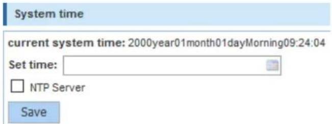
| Index | Specify the history table index number. |
| Set time | Click in order to set the time for the Intellinet Network Solutions switch manually. |
| [ ] NTP Server | Activate this option if you want the Intellinet Network Solutions switch to obtain the system time from an NTP server. For that to work, be sure to provide a proper gateway and DNS server address. |
6.17.1.2 System Restart

Click "Restart" in order to have the Intellinet Network Solutions switch perform a system restart.
6.17.1.3 Password

On this screen, you can change the administrator password. The default password is "1234".
6.17.1.4 EEE Enable

Energy-Efficient Ethernet (EEE) is a set of enhancements to the twisted-pair and backplane Ethernet family of computer networking standards that allow for less power consumption during periods of low data activity. The intention was to reduce power consumption by 50% or more while retaining full compatibility with existing equipment. The Institute of Electrical and Electronics Engineers (IEEE), through the IEEE 802.3az task force developed the standard. EEE is a power saving option that reduces the power usage when there is low or no traffic utilization. When there is no traffic, EEE powers down circuits.
When a port is powered down to save power, the outgoing traffic is stored in a buffer until the port is powered up again. Using this technique, more power can be saved if the traffic can be buffered up until a large burst of traffic can be transmitted. Keep in mind that buffering traffic will give some latency in the traffic.
Should you encounter problems related to EEE (e.g., related to auto negotiation), you can disable EEE support and the Intellinet Network Solutions switch will no longer use it.
6.17.1.5 SSH Login

Activate SSH support by setting the SSH CONFIG to "OPEN".
6.17.1.6 Telnet Login

Activate Telnet support by setting the TELNET CONFIG to "OPEN".
6.17.1.7 System Log
The Intellinet Network Solutions switch has the ability to create a history log of important events. These logs can be stored either in the switch's own memory or on a remote Syslog server. In order to utilize the logging service, you must first enable it.

| Index | Specify the history table index number. |
| Log switch | Select one of the eighteen Gigabit port from the drop-down list. |
| Server IP | Provide the IP address of the Syslog server. Note that the Syslog server must be set to UDP port 514. |
| Send log level | Define the amount of detail you wish the Intellinet Network Solutions switch to log. |
6.17.2 System Update

Intellinet Network Solutions may release a new firmware for this switch to provide new functions and, perhaps, bug fixes. You can install the new firmware on this screen. Should a new firmware be made available, it will be available at intellinetnetwork.com/barcode/508278.

How to install the new firmware:
- Download the firmware from the web site.
- The correct file extension for the firmware is ".bix".
- Click "Browse" and select the ".bix" file from your computer's HDD.
- Click "Start Upgrade."
- Confirm your decision by clicking OK. The upgrade will now begin.
-
Hope that there won't be a power outage during the next 3 minutes.
-
If the firmware is a compressed file such as RAR, 7Z or ZIP, you need to uncompress the file first before it can be installed on the Intellinet Network Solutions switch.

Uploading the firmware...

The device will automatically restart after this operation, please wait
Note that if you still see the message above after 5 minutes, open a new browser window and re-connect to the IP address of the Intellinet Network Solutions switch (default = http://192.168.2.1).
6.17.3 Configuration Management

6.17.3.1 Config Export and Import
This function allows an administrator to backup and restore the configuration data of the Intellinet Network Solutions switch.
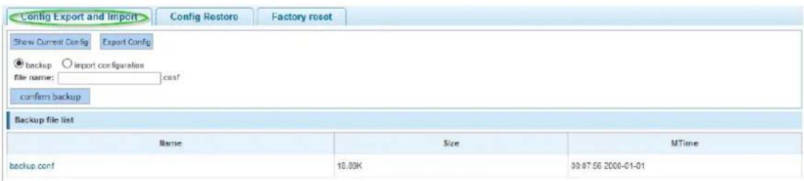
| Index | Specify the history table index number. |
| Show Current Config | Shows the current switch configuration in a pop-up window. |
| Export Config | Saves the current configuration data to a file on your computer's HDD. |
| backup | When a file name is provided (see below), click this button to create a backup of the configuration, which the Intellinet Network Solutions switch will keep in its memory. The config-restore function provides access to these backups and lets you restore them, delete them, rename them or save them to your computer's HDD. |
| File name | Filename for backup, e.g., backup. |
| Import configuration | In order to upload a previously saved configuration, activate this option, and then click on "Browse" and select the correct ".conf" from your computer's HDD. Click the "Import Configuration" button to begin. |
6.17.3.2 Config Restore
The config restore function provides access to backups that were created previously and lets you restore them, delete them, rename them or save them to your computer's HDD.
6.17.3.3 Factory Reset

This feature allows an administrator to restore all settings to the factory default values. If you managed to lock yourself out from configuring the switch and have lost access to the web admin interface, you can reinstate the factory default settings by pressing the reset button on the front of the switch for 20 seconds.
6.17.4 Config Save
SYSTEM
- System Config
- System Update
- Config Management
- Config Save
The Intellinet Network Solutions 8-Port Gigabit Ethernet PoE+ Web-Managed Switch provides a myriad of configuration options, many of which are designed for experienced network administrators and aren't easy to configure. It would be a real shame if all the configuration data was lost after a power failure or after the switch was restarted. In order to make the configuration permanent, it needs to be saved.
Save settings
6.17.5 Administrator Settings
SYSTEM
- System Config
- System Update
- Config Managem...
- Config Save
- Administrator Pr...
You can create new user accounts and modify existing ones on this page. A user account that does not have administrator right can only monitor the main status information of the Intellinet Network Solutions switch but cannot make any changes to the configuration.
Administrator privileges
![user name: new password: confirm password: add user user list user name operation admin user first page prev page [1] next page last page 1 / 1page](/content/2026/05/905137/images/5888fc77bac003f5c1bf2ee4d0b3893ab13b162ef93c5b978a5fe9dcad3b375e.jpg)
| Index | Specify the history table index number. |
| User name | When creating a new account, type in the new username. If editing an existing account, the field will be read-only. |
| New password | Type in the new password. |
| Confirm new password | Repeat the new password. |
6.17.6 Information Collect

Collect
Click on the button to create a file that contains the configuration data of the Intellinet Network
Solutions switch. After a few seconds, you will be asked to open or save the file (or whatever web browser default action for unknown files is in place on your system). This information can be useful when it comes to troubleshooting technical problems.
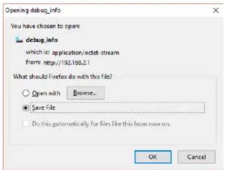
7 WASTE ELECTRICAL & ELECTRONIC EQUIPMENT
DISPOSAL OF ELECTRIC AND ELECTRONIC EQUIPMENT
(Applicable in the European Union and other European countries with separate collection systems)
ENGLISH: This symbol on the product or its packaging means that this product must not be treated as unsorted household waste. In accordance with EU Directive
2012/19/EU on Waste Electrical and Electronic Equipment (WEEE), this electrical product must be disposed of in accordance with the user's local regulations for electrical or electronic waste. Please dispose of this product by returning it to your local point of sale or recycling pickup point in your municipality.
This equipment has been tested and found to comply with the limits for a Class B digital device, pursuant to Part 15 of FCC Rules. These limits are designed to provide reasonable protection against harmful interference in a residential installation. This equipment generates, uses, and can radiate radio frequency energy and, if not installed and used in accordance with the instructions, may cause harmful interference to radio communications. However, there is no guarantee that interference will not occur in a particular installation. If this equipment does cause harmful interference to radio or television reception, which can be determined by turning the equipment off and on, the user is encouraged to try to correct the interference by one or more of the following measures: reorient or relocate the receiving antenna; increase the separation between the equipment and receiver; connect the equipment into an outlet on a circuit different from that to which the receiver is connected; consult the dealer or an experienced radio technician for help.
CE
ENGLISH: This device complies with the requirements of CE 2014/30/EU and/or 2014/35/EU. The Declaration of Conformity for is available at:
intellinetnetwork.com/barcode/508278


North America
IC Intracom America
550 Commerce Blvd.
Oldsmar, FL 34677, USA
Asia & Africa
IC Intracom Asia
4-F, No. 77, Sec. 1, Xintai 5th Rd.
Xizhi Dist., New Taipei City 221, Taiwan
Europe
IC Intracom Europe
Löhbacher Str. 7, D-58553
Halver, Germany
All trademarks and trade names are the property of their respective owners.
- 8-Port Gigabit Ethernet PoE+ Web-Managed Industrial Switch with 2 SFP Ports
- INTELLINET®
- TABLE OF CONTENTS
- Product Introduction....4
- Installing and Connecting the Switch 8
- Connection to the Switch 10
- Saving the Configuration....12
- Switch Configuration....13
- Quick Setup 15
- VLAN 25
- Fault/Safety 31
- PoE 43
- Spanning Tree Protocol (STP) 47
- DHCP Relay Agent 53
- DHCP Server 55
- IGMP Snooping....57
- Terminal Access Controller Access-Control System (TACACS+) 61
- Radius....63
- AAA....65
- QoS – Quality of Service 66
- Address Table.... 69
- SNMP....70
- System....78
- WASTE ELECTRICAL & ELECTRONIC EQUIPMENT 86
- WARRANTY....86
- REGULATORY STATEMENTS....87
- PRODUCT INTRODUCTION
- PRODUCT OVERVIEW
- FEATURES
- SPECIFICATIONS
- Standards
- Power
- Environmental
- Package Contents
- EXTERNAL COMPONENT DESCRIPTION
- Front Panel
- Reset button (Reset):
- Left Panel
- Terminal block
- Grounding terminal
- Rear Panel
- Guide rail seat
- PACKAGE CONTENTS
- INSTALLING AND CONNECTING THE SWITCH
- INSTALLATION
- DIN-rail Installation
- Desktop Installation
- TERMINAL BLOCK INSTALLATION / POWER ON THE SWITCH
- CONNECTION TO THE SWITCH
- CONNECTING COMPUTER
- How to Log IN TO THE SWITCH
- SWITCH CONFIGURATION
- HOME
- Port Information
- Port Information, Equipment Configuration and Port Statistics
- QUICK SETUP
- Quickly Set
- next step
- PORT SETTINGS
- Basic Config
- PORT
- Port Aggregation
- Port Mirroring
- Port Mirroring
- Port speed limit
- Broadcast storm
- Storm Control
- Port isolation
- Configuration Example \*\*\*:
- PC1 on port 1:
- PC2 on port 2:
- PC3 on port 3:
- NAS on Port 4:
- Router on Port 5:
- VLAN
- VLAN
- Vlan Config
- Trunk Port Settings
- Hybrid Port Settings
- Setup Example \*\*\*
- Set up LAN Switch #1:
- Hybrid port settings:
- FAULT/SAFETY
- Anti Attack
- Command Usage
- DoS
- IP Source Guard
- IP MAC Port Binding
- Channel Detection
- Ping
- Tracert
- Cable Test
- ACL Access Control List
- Timetables
- Operation
- ACL
- Apply ACL
- PoE
- PoE Config
- PoE
- Management
- Temperature Distribution
- PoE Port Config
- PoE Delay Config
- PoE Delay
- SPANNING TREE PROTOCOL (STP)
- Creating a Stable STP Topology
- STP Port States
- MSTP Region
- MSTP
- MSTP Bridge
- DHCP RELAY AGENT
- DHCP RELAY
- DHCP Relay
- Option82
- Circuit Control
- Proxy Remote
- IP Address
- DHCP SERVER
- DHCP Config
- DHCPserver
- - Dhcp Config
- Enable Config
- Pool Config
- Option Config
- Bind Config
- Gateway Config
- DNS Config
- IGMP SNOOPING
- Multicast Service
- IGMP Config
- IGMP
- IGMP Config Options
- IGMP Config
- IGMP Port Config
- IGMP VLAN Config
- IGMP config options
- IGMP Filter Policy Config
- TERMINAL ACCESS CONTROLLER ACCESS-CONTROL SYSTEM (TACACS+)
- TACACS+
- TACACS+ Config
- RADIUS
- RADIUS
- Radius General Config
- AAA
- Enable Config
- Region Config
- QoS – QUALITY OF SERVICE
- QoS Rules
- Queue Config
- Queue Mapping
- CoS-Queue-Map
- DSCP-CoS-Map
- Port-CoS-Map
- ADDRESS TABLE
- Address Table Config
- MAC Add & Delete
- MAC study & aging
- MAC Filter
- SNMP
- SNMP Config
- Community Config
- Group Config
- User Config
- View Config
- RMON Config
- Statistics Group
- History Group
- Alarm Group
- Event Group
- SYSTEM
- System Config
- SYSTEM
- - System Config
- System Settings
- System Restart
- Password
- EEE Enable
- SSH Login
- Telnet Login
- System Log
- System Update
- Configuration Management
- Config Export and Import
- Config Restore
- Factory Reset
- Config Save
- Save settings
- Administrator Settings
- Information Collect
- Collect
- WASTE ELECTRICAL & ELECTRONIC EQUIPMENT
- DISPOSAL OF ELECTRIC AND ELECTRONIC EQUIPMENT
- CE
- North America
- Asia & Africa
- Europe
Brand : Intellinet
Model : 508278
Category : Switch